HOLIDAY DONATION DRIVE - SUPPORT MSW - DO YOUR PART TO KEEP THIS GREAT FORUM GOING! (Only 75 donations so far out of 49,000 members - C'mon guys!)
×


aydingocer
-
Posts
916 -
Joined
-
Last visited
Content Type
Profiles
Forums
Gallery
Events
Everything posted by aydingocer
-
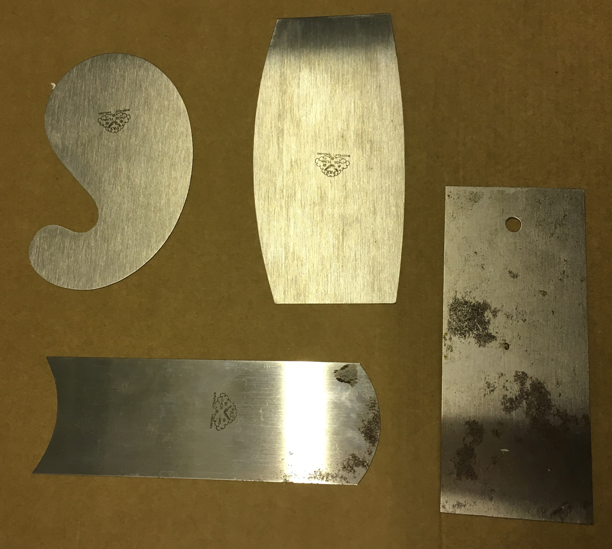
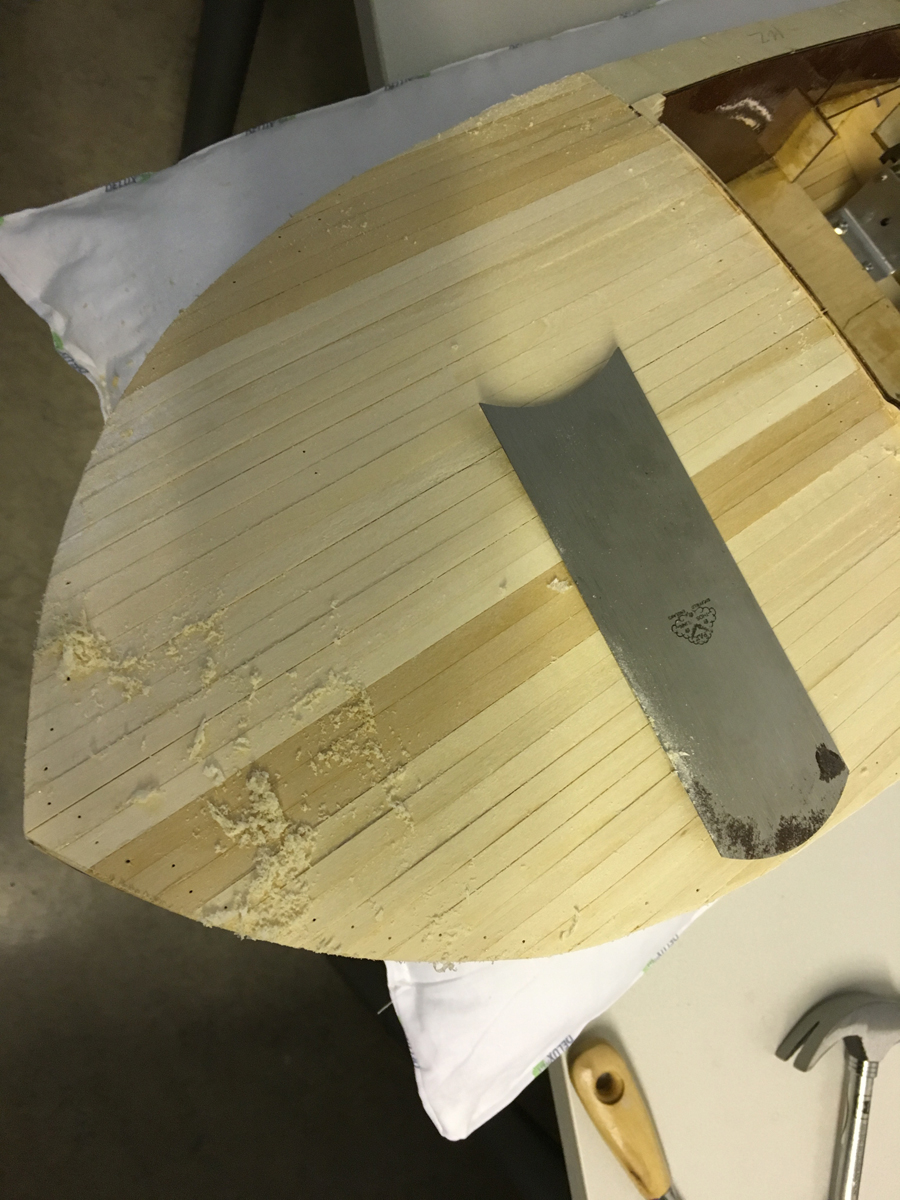
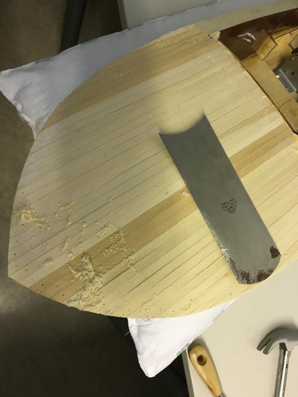
 Back to work. Before sanding I decided to use some scraper in order to get rid of the glue residues and to level the stripes for helping the sanding process. I have this set of scrapers with different contours quite useful for this boat, which has rather curvy surface: They work quite effectively indeed:
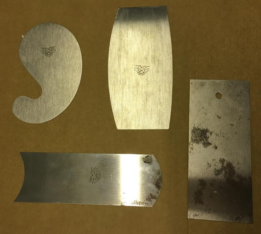
- 414 replies
-
- 8
-

-
- riva aquarama
- amati
- (and 2 more)
-
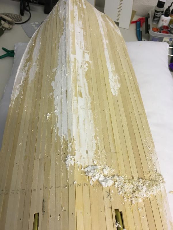
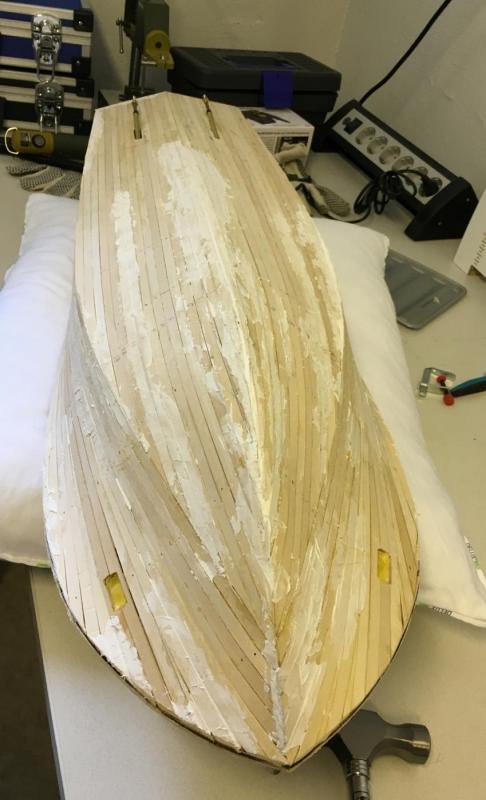
Gaps filled with help of a spatula. Now a lunch break (until it dries):
- 414 replies
-
- 4
-
-
- riva aquarama
- amati
- (and 2 more)
-
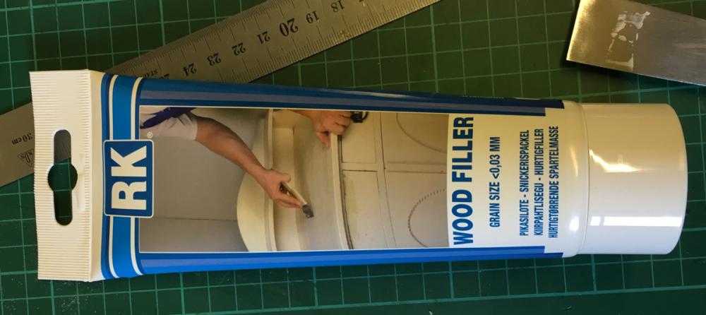
Next in line is to fill the gaps. I use this furniture grade water based wood filler which I found in a local hardware store. It is quite smooth and according to the specs it dries in 1 hour per mm thickness:
- 414 replies
-
- 5
-
-
- riva aquarama
- amati
- (and 2 more)
-
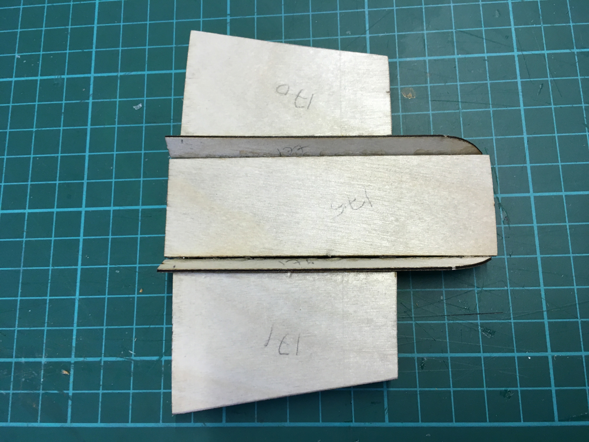
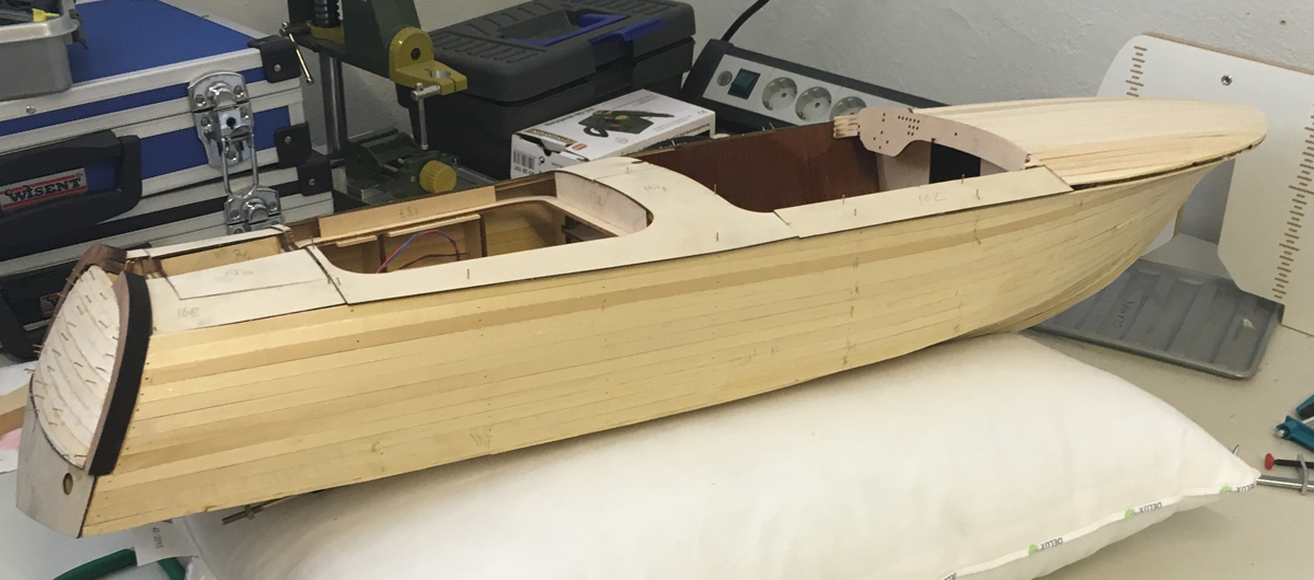
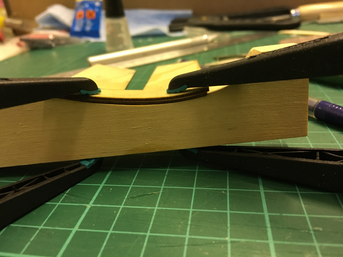
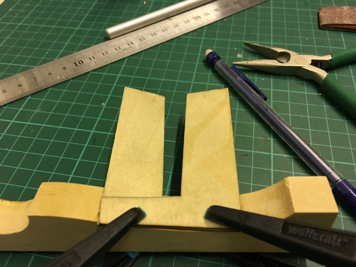
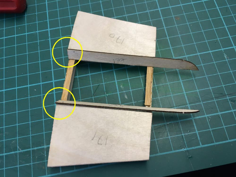
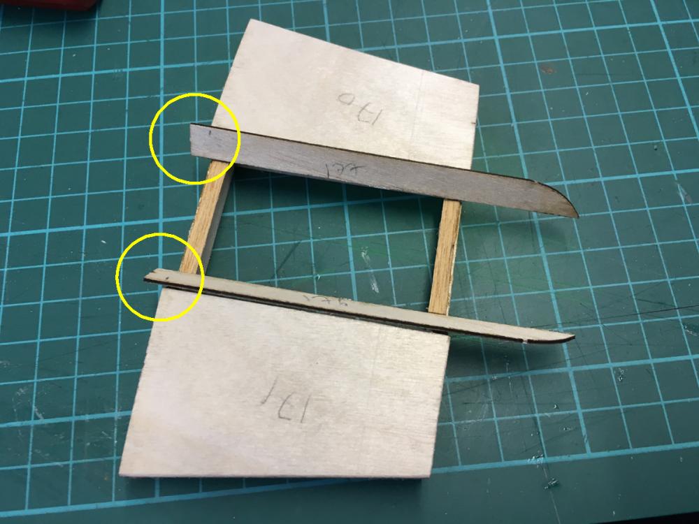
BUILD DAY 19. COMPLETING 1st PLANKING. No, I am not one of those who have been hypnotised by Pokemon Go, which became available in Finland as of yesterday! I have had roughly 4 hours today to finally complete 1st planking and start preparing the hull for the second planking. First, finishing the first planking of the removable engine cover (1st planking of this section is made by veneer sheets). After the planks are glued, the section should fit in its space nicely. Some parts in the stern prevented it. I had to use a rasp at the stern to get rid of those obstacles. Here are a few details: Positioning of planks (parts 175, 76, 177) require some attention. The first photo below is a demonstration of wrong positioning, even though it looks tempting: This is the right way: If you look carefully at where the middle part sits, you will notice that I glued thin strips, which will raise the middle piece about a millimetre or so. Without them, the middle piece was touching the stern. so that was the reason. The middle part in place, all glued: Lid in place:

- 414 replies
-
- 6
-
-
- riva aquarama
- amati
- (and 2 more)
-
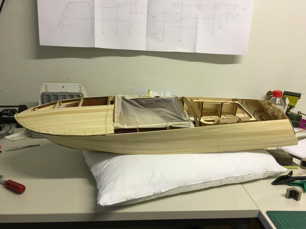
END of BUILD DAY 18. 1,5 hours today. 60,5 hours into build in total. This is the status at the end of day. Thanks for watching.

- 414 replies
-
- 8
-
-
- riva aquarama
- amati
- (and 2 more)
-
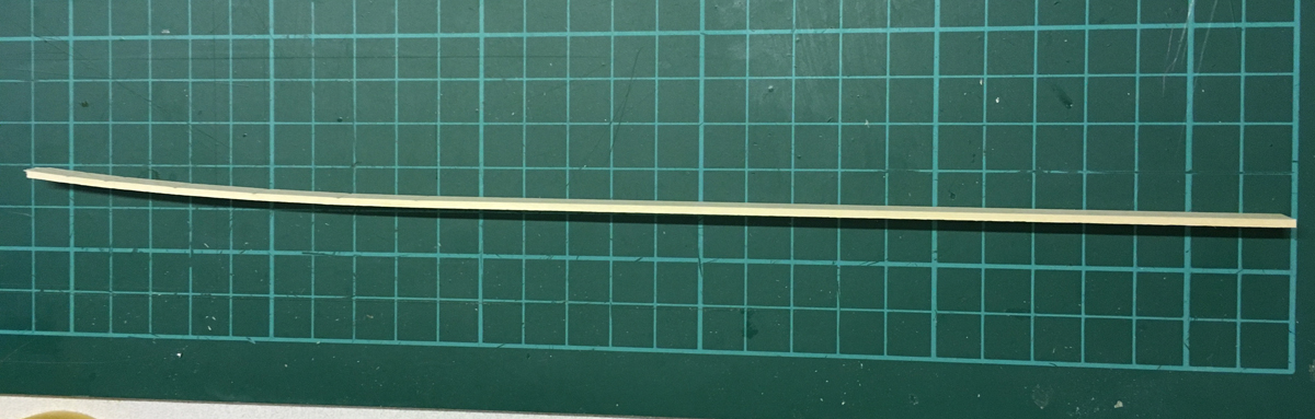
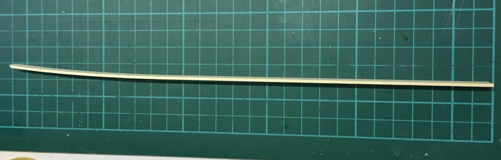
This is how much you'll have to bend the stern planks on the average. I did not have to soak them, my plank bender was good enough to handle it:
- 414 replies
-
- 5
-
-
- riva aquarama
- amati
- (and 2 more)
-
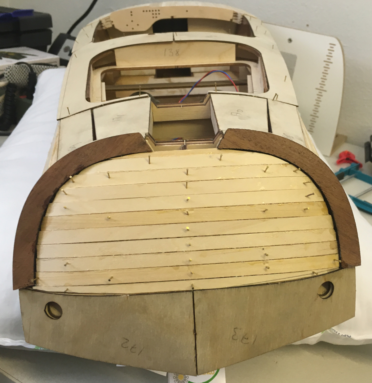
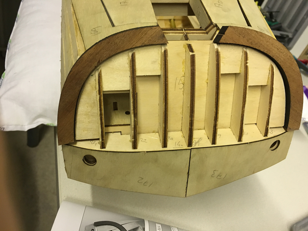
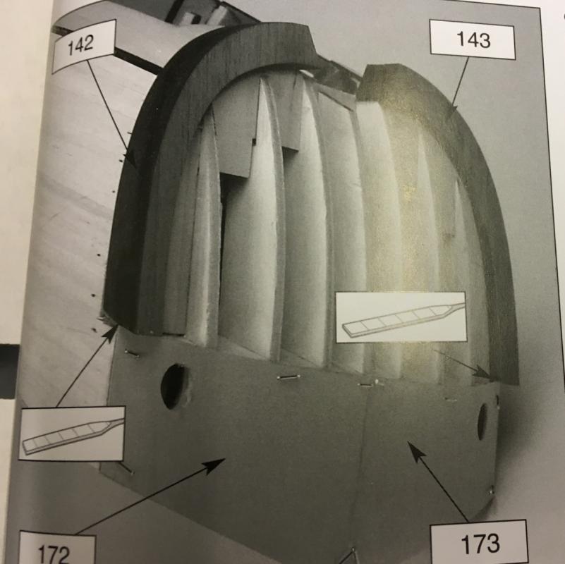
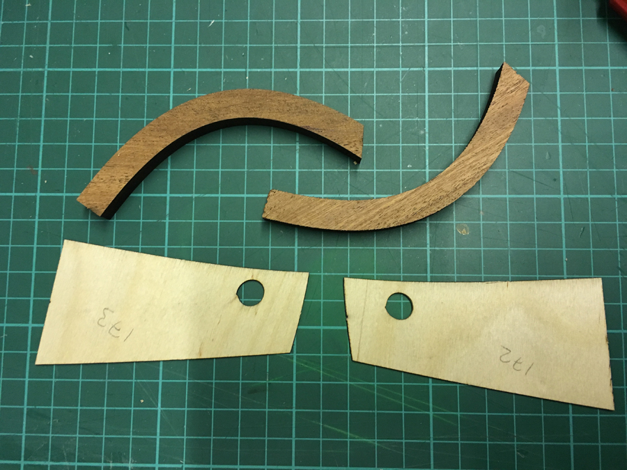
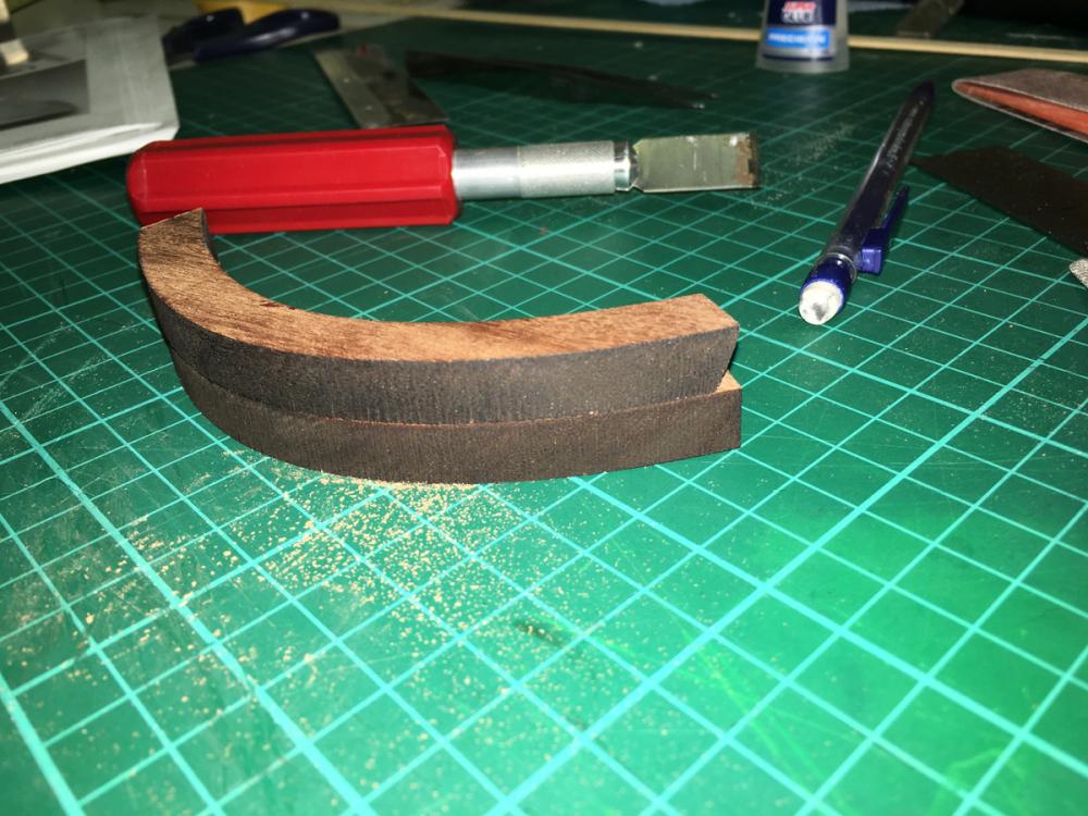
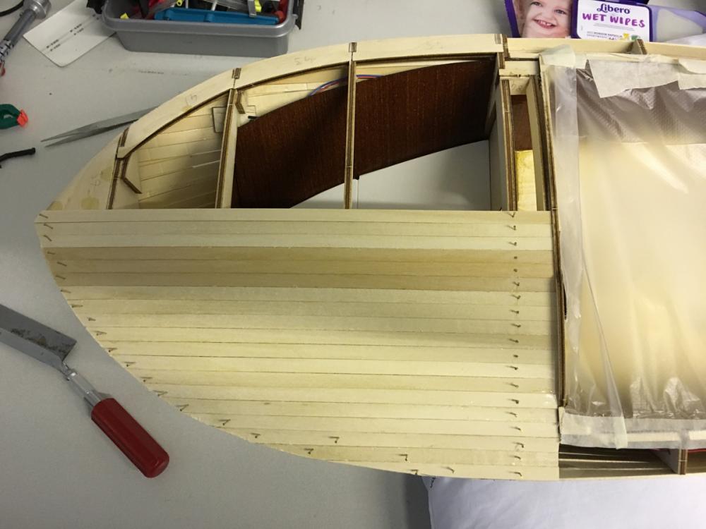
Glued the thick curvy mahogany frame which I had filed ready yesterday. They are now covering around the stern. Apparently stern planking should be done in such a way that the 1st planking (which I am doing now using 1,5x7mm lime as the previous plankings) shall be level with the veneer parts on the bottom ( i.e. parts 172 and 173), while leaving some offset with the mahogany frames, so that they will be level with the 2nd planking (which will be done using 1,5x8mm mahogany strips). So I glue them around 1,5mm offset (see the photo):
- 414 replies
-
- 6
-
-
- riva aquarama
- amati
- (and 2 more)
-
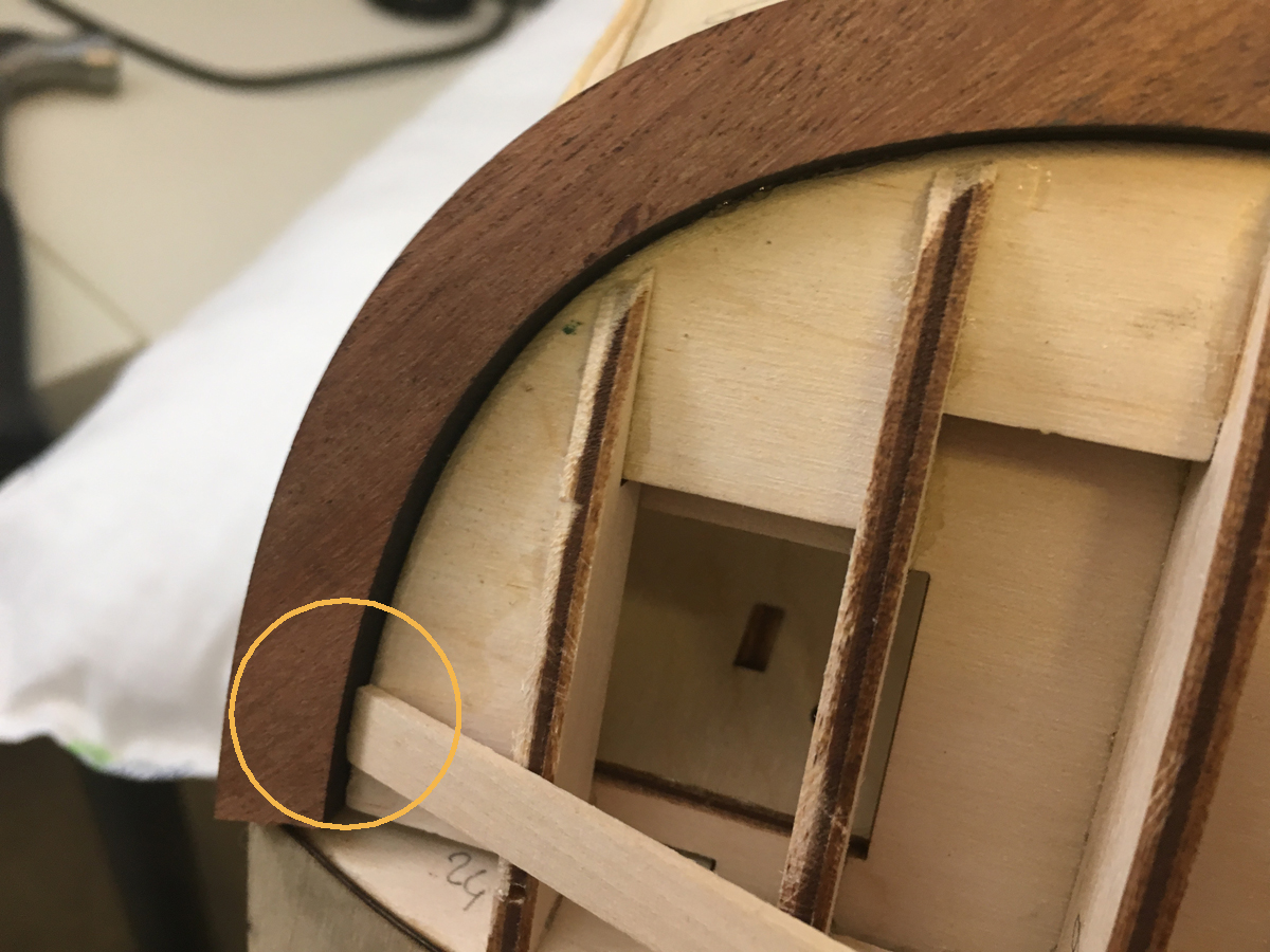
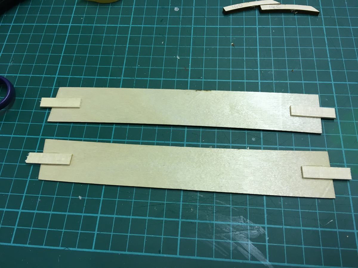
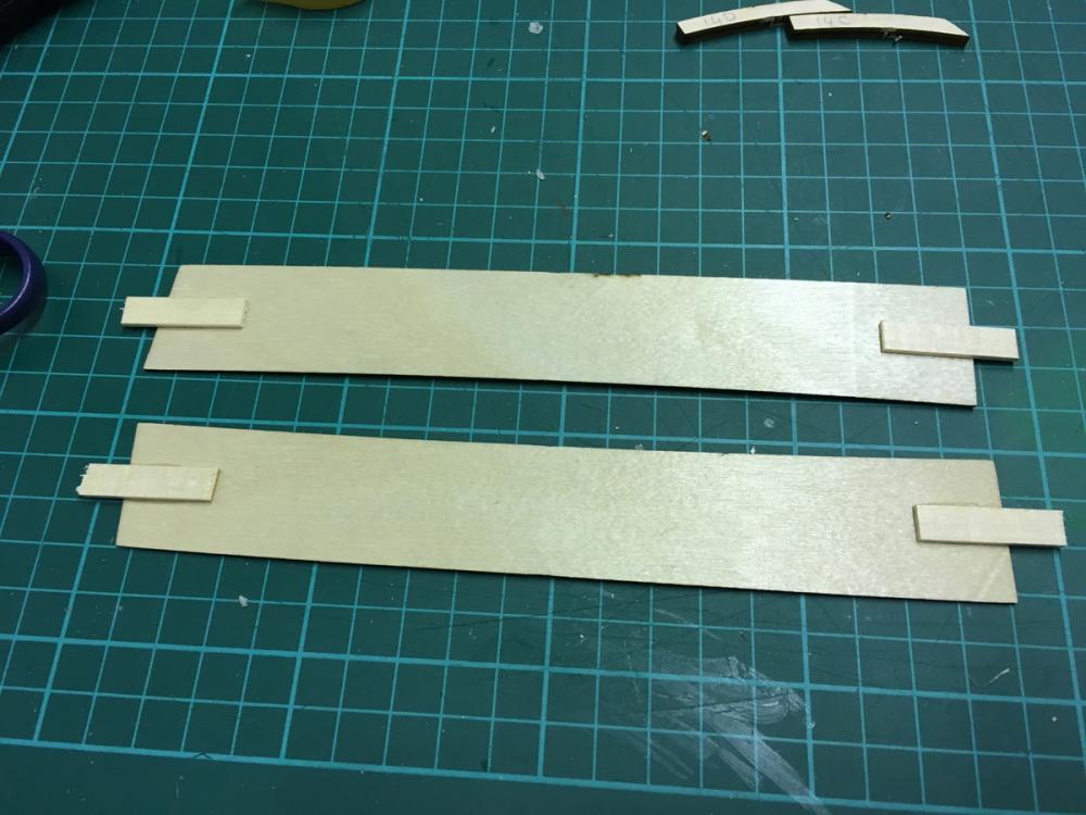
BUILD DAY 18. STERN 1st PLANKING. Today I had some 1,5 hours which I could use for 1st planking the stern. But before that I glued 2 small support pieces:


- 414 replies
-
- 5
-
-
- riva aquarama
- amati
- (and 2 more)
-
Yep, I agree Antony and Carl. This is one of the main purposes of sharing your build in a forum: Deliver your experience to the other builders as someone who has been there.
- 414 replies
-
- 3
-
-
- riva aquarama
- amati
- (and 2 more)
-
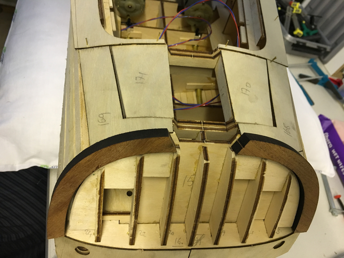
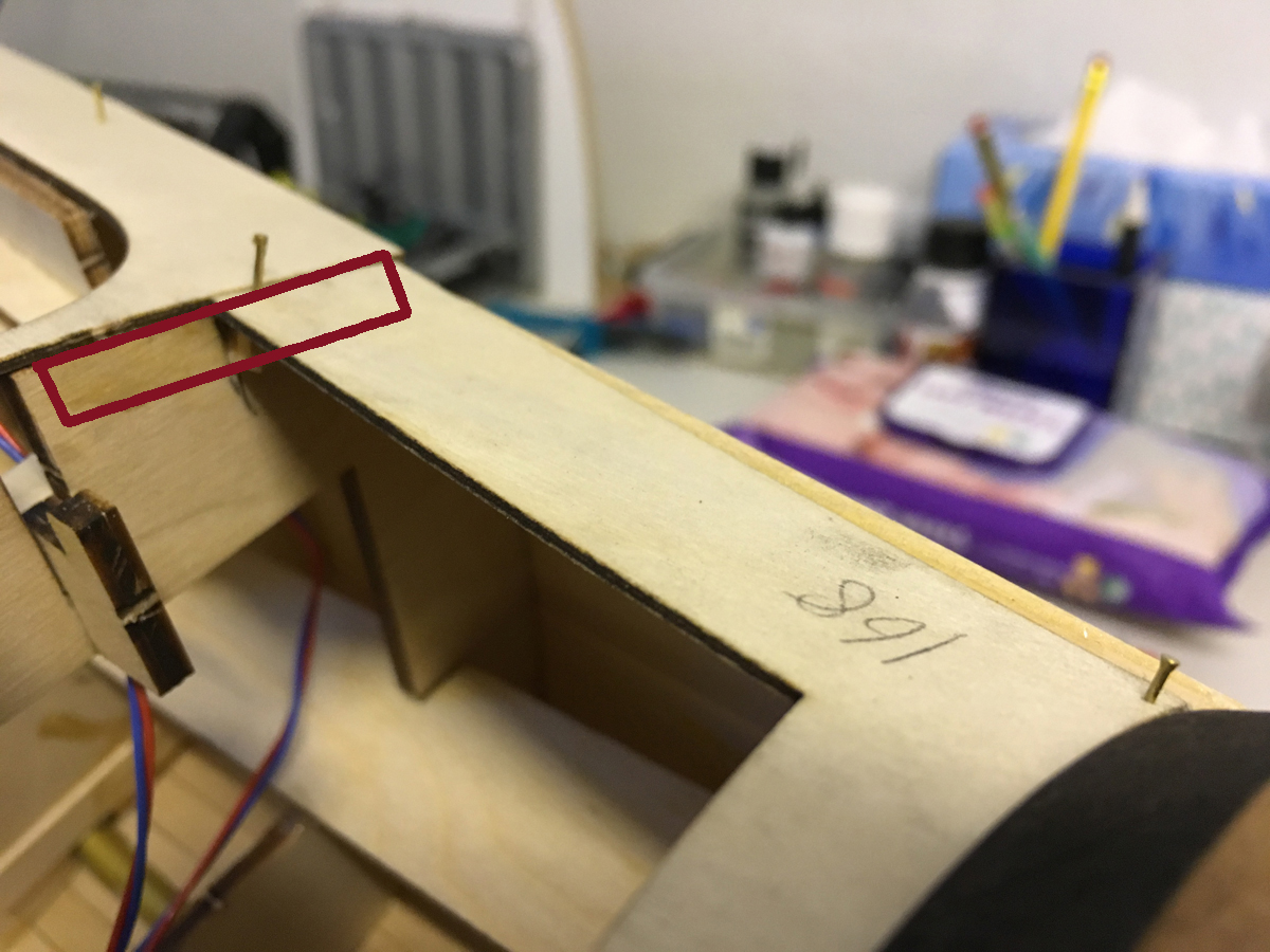
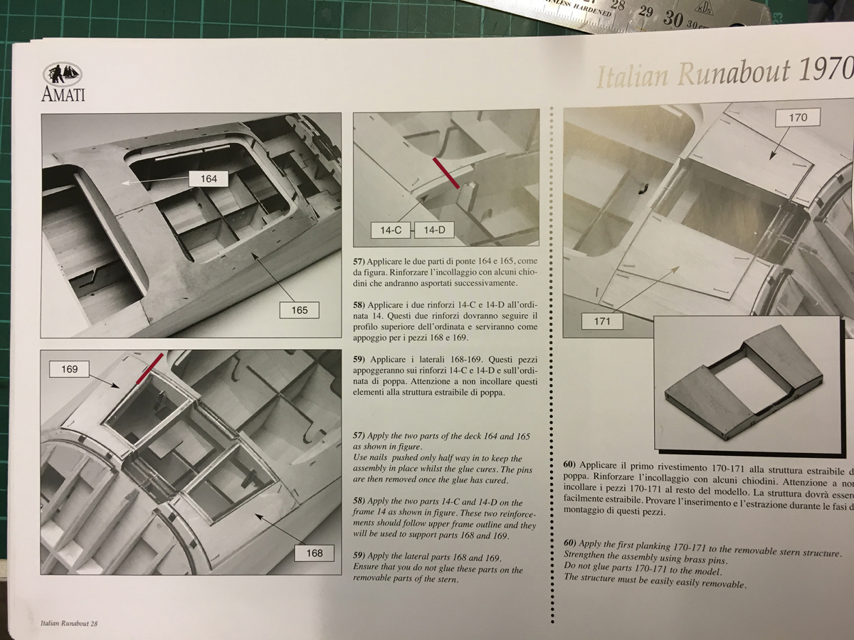
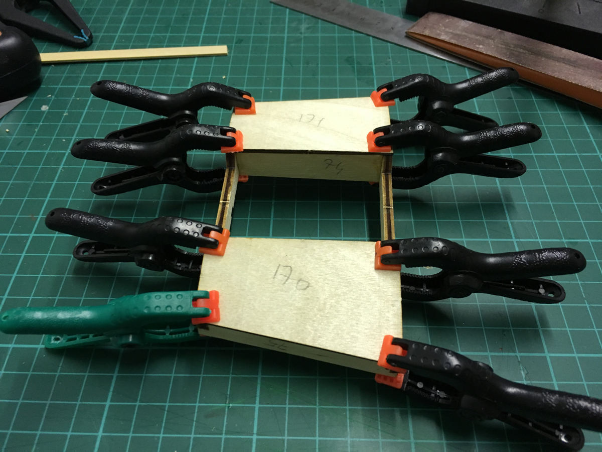
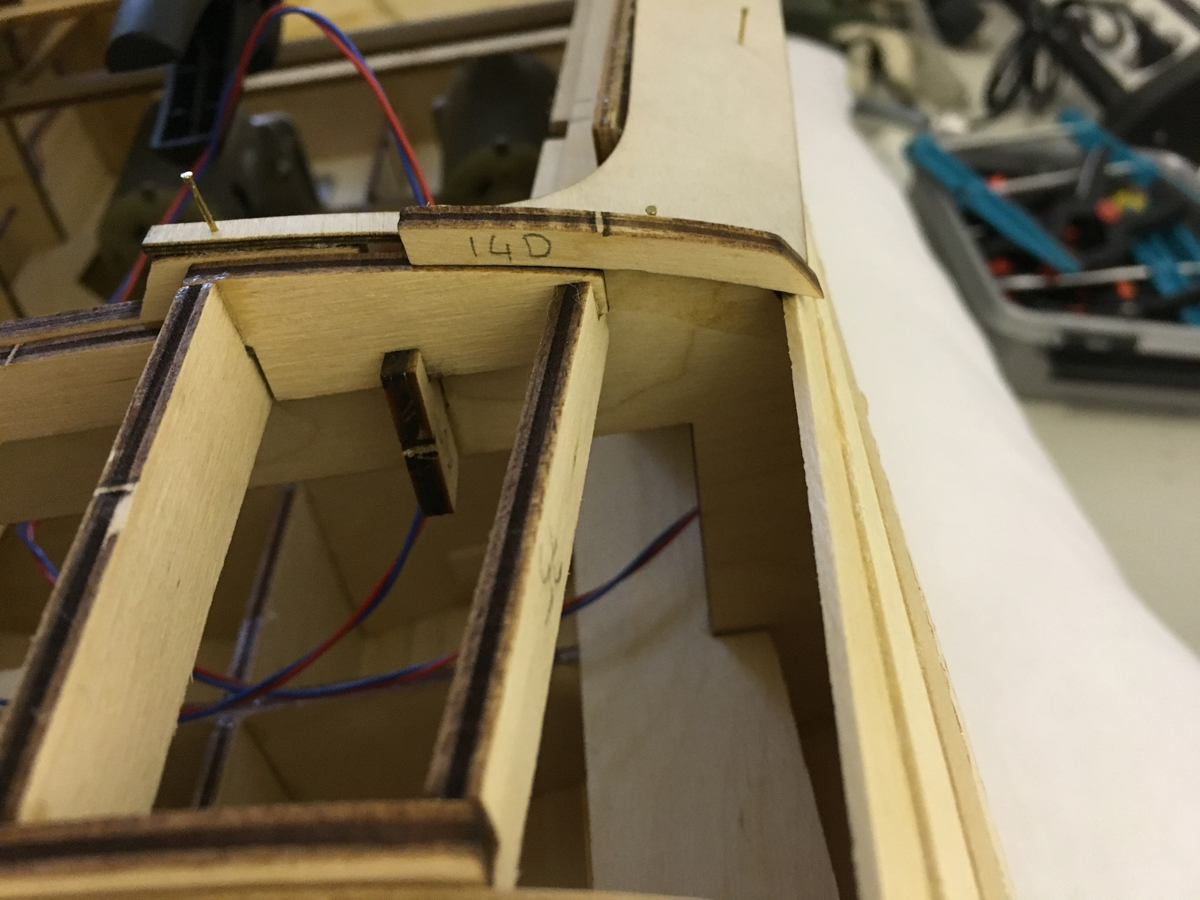
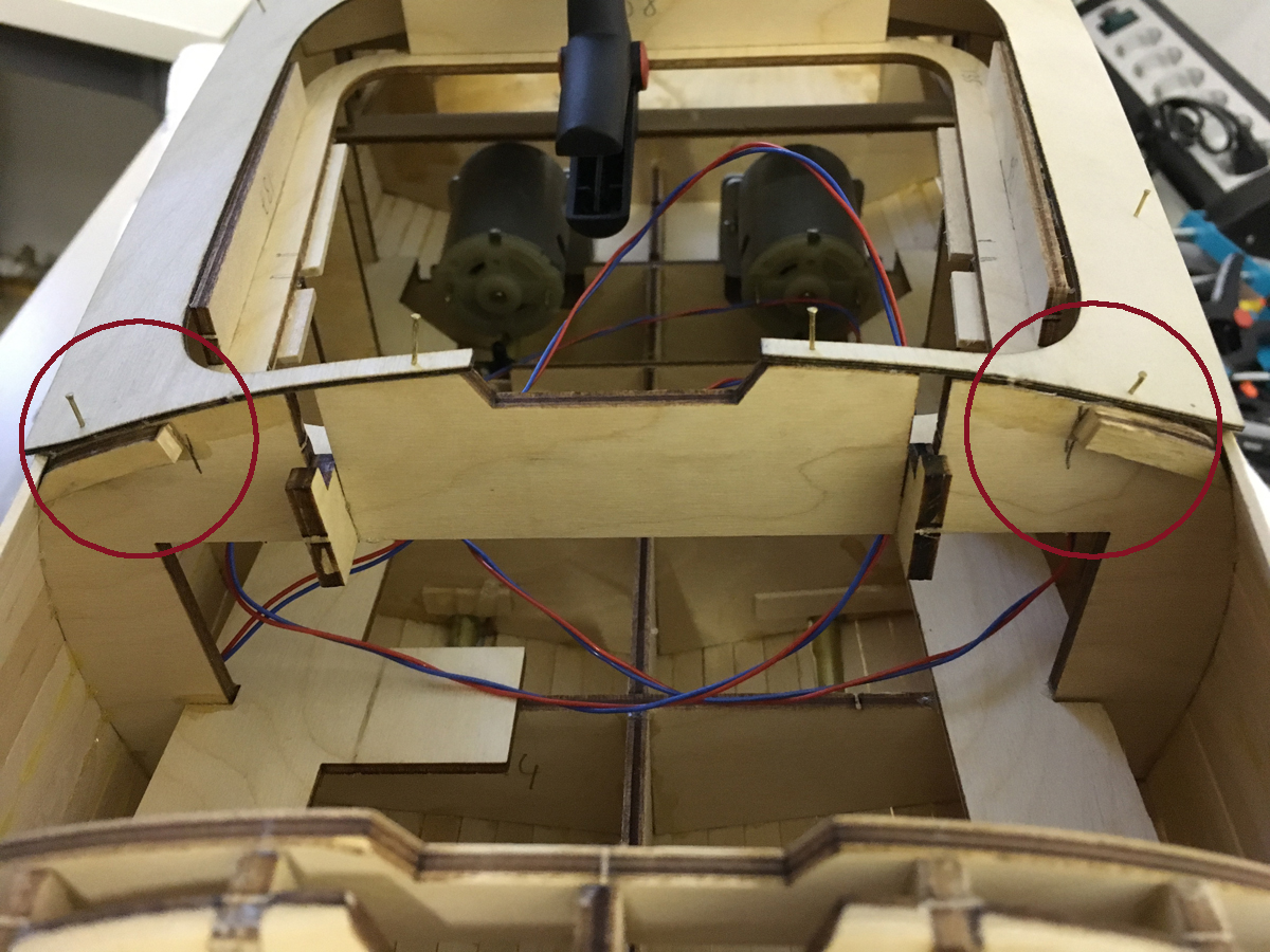
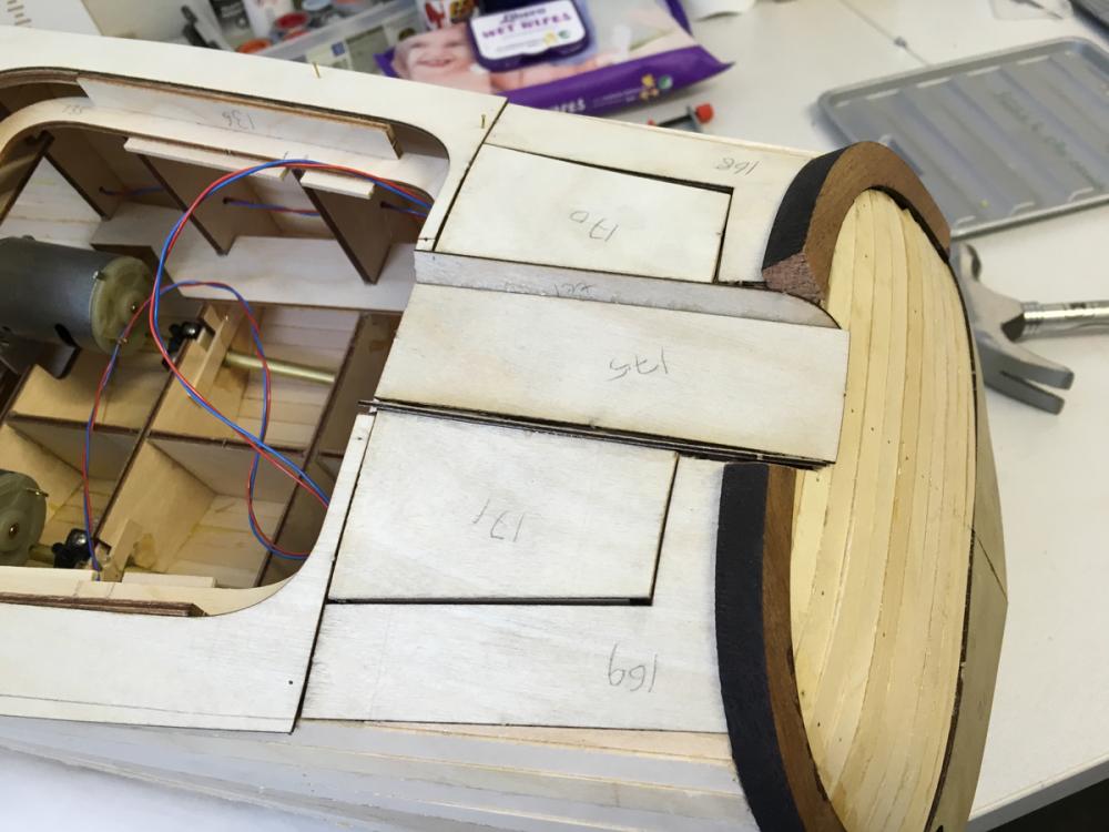
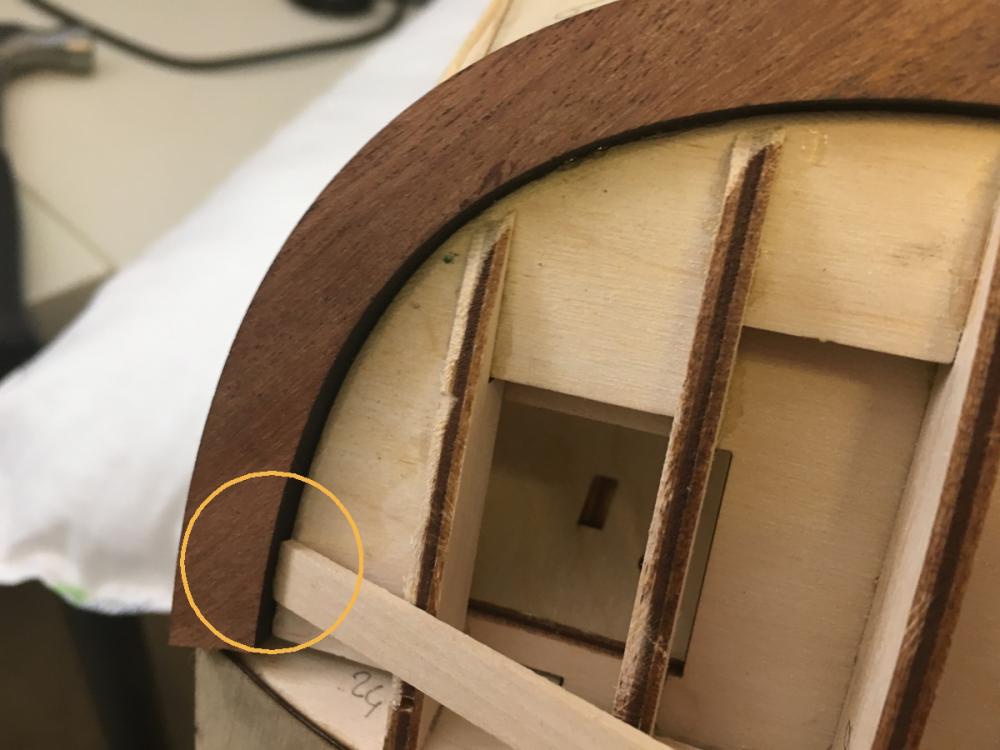
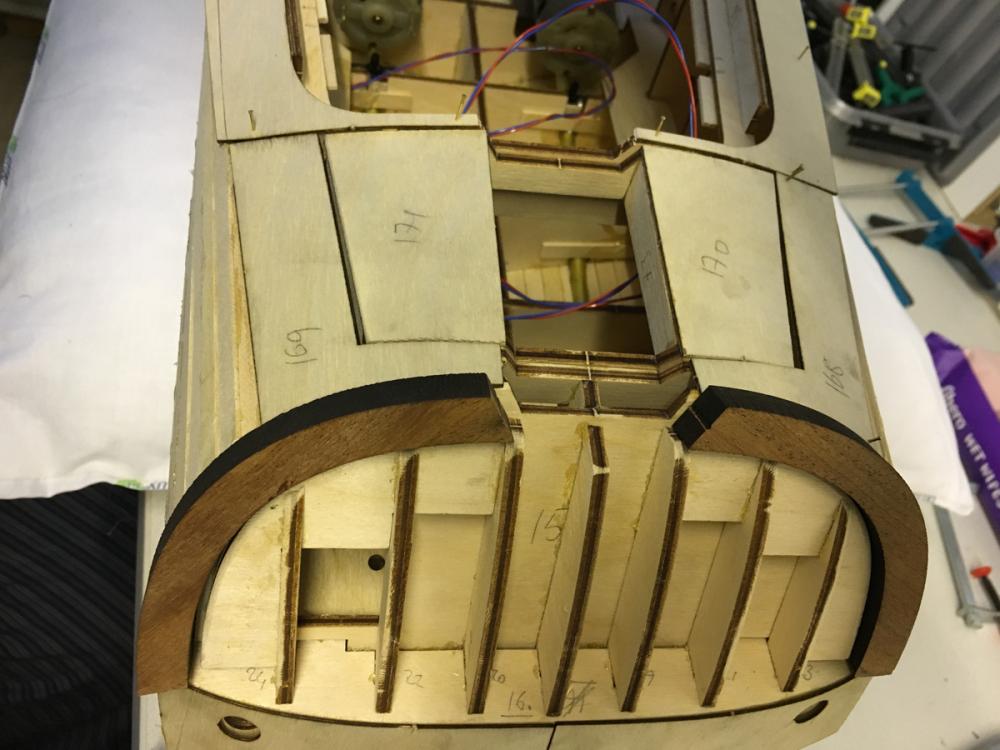
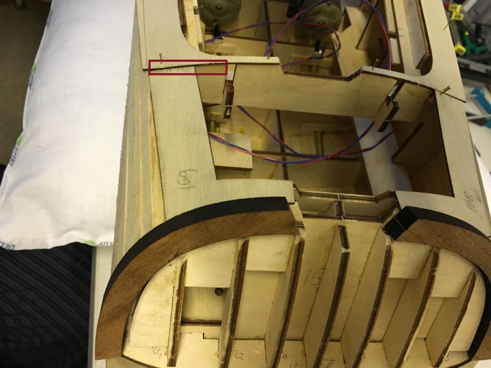
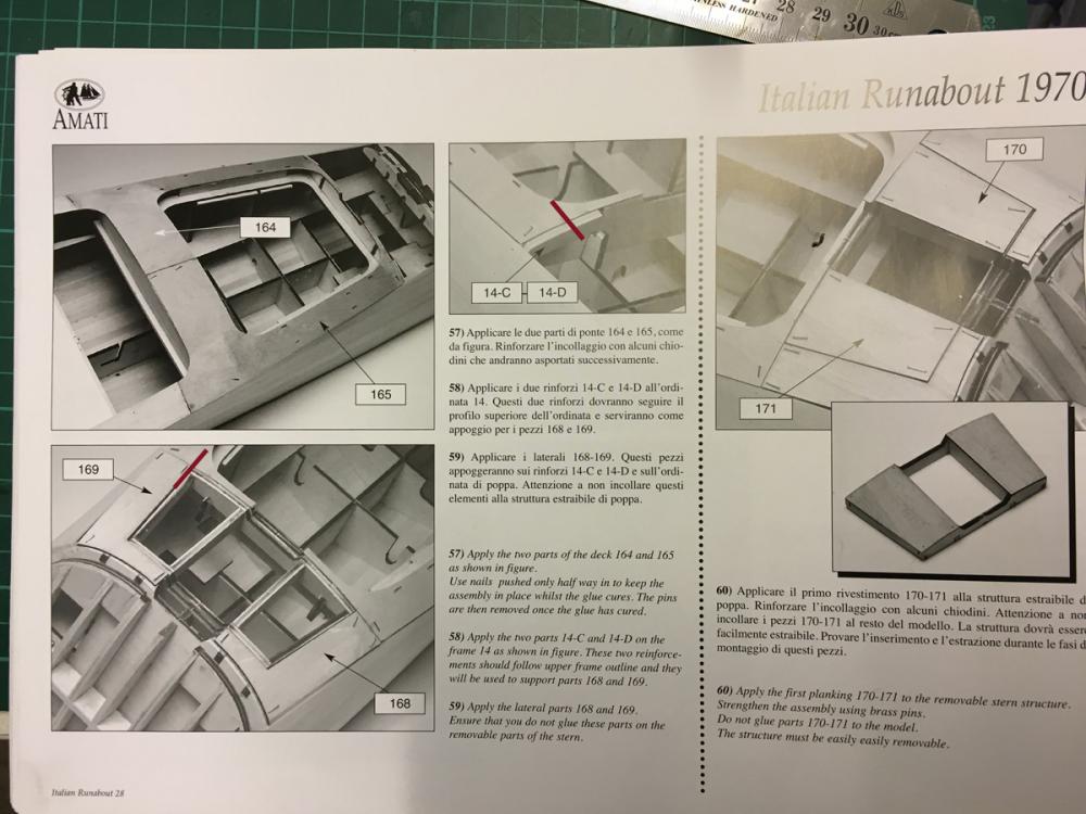
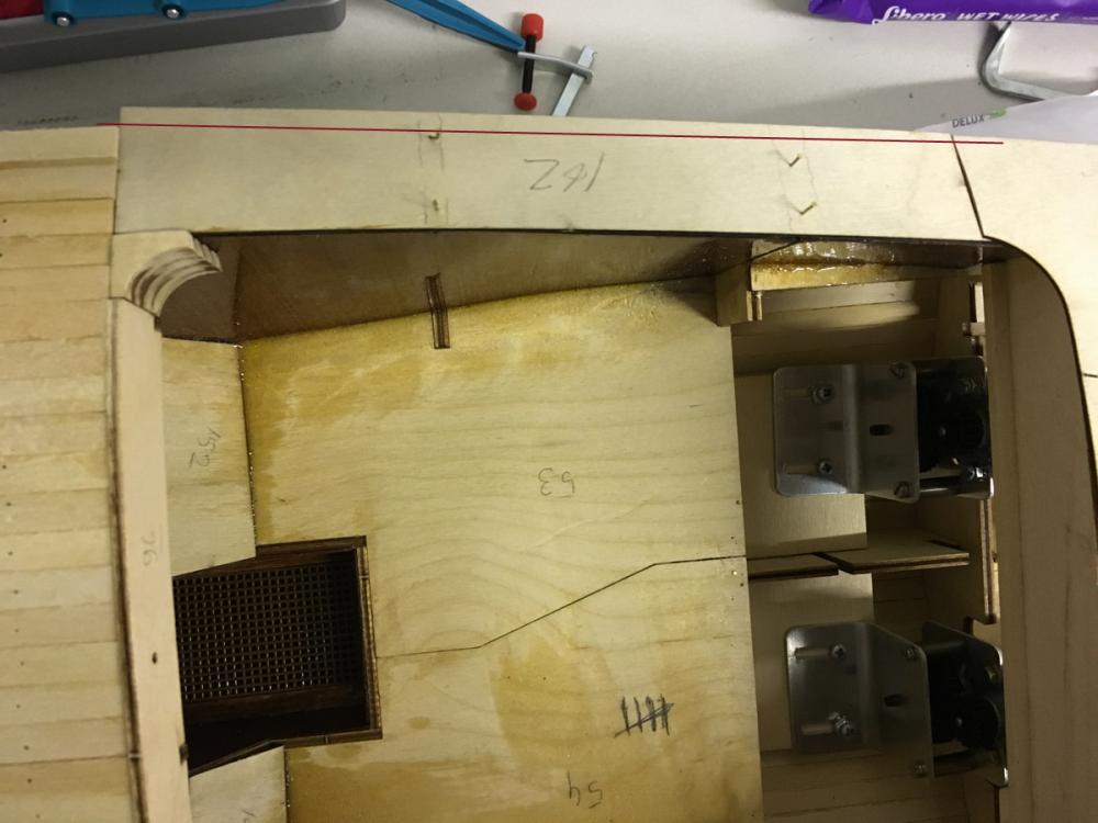
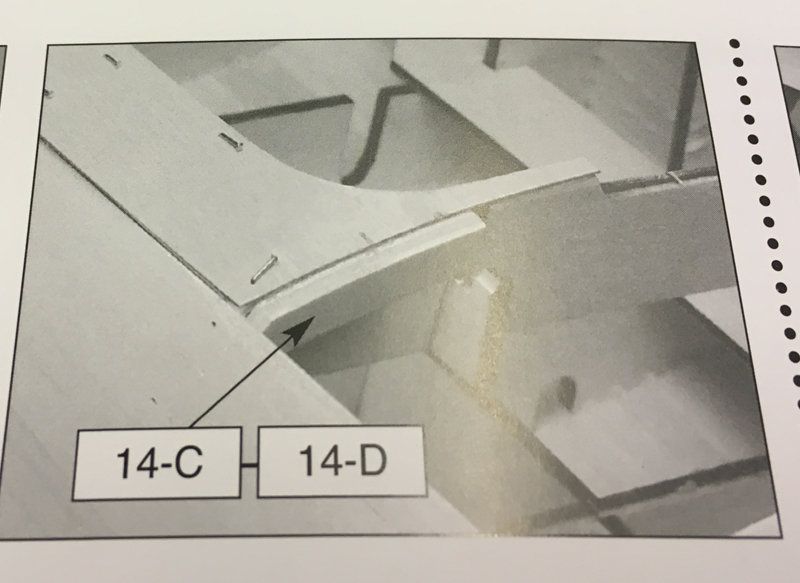
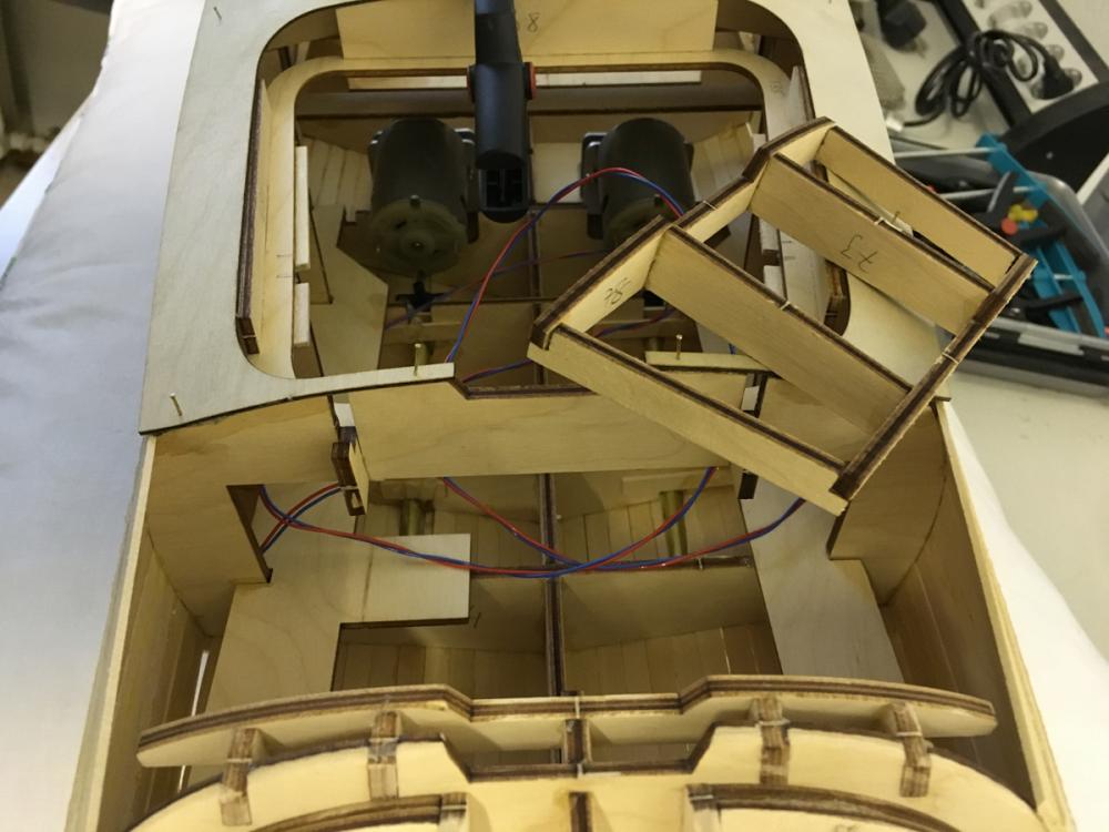
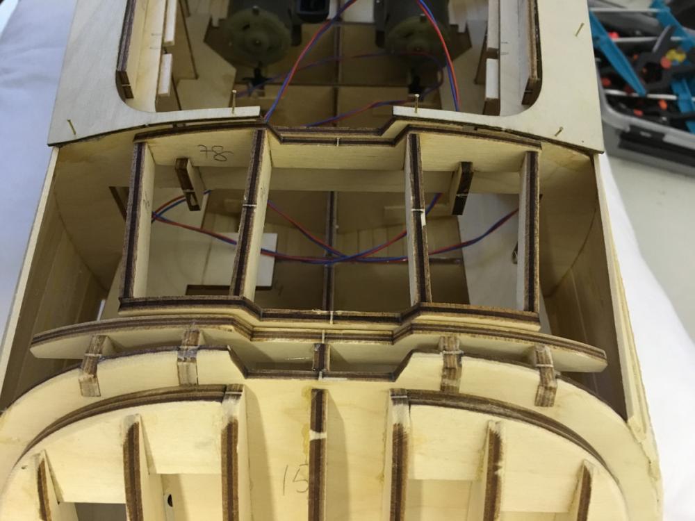
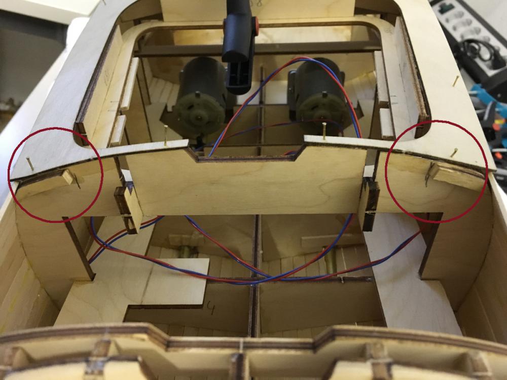
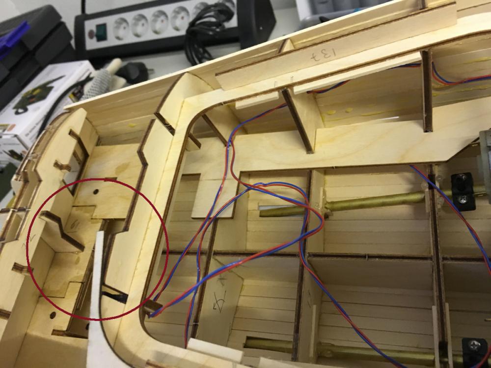
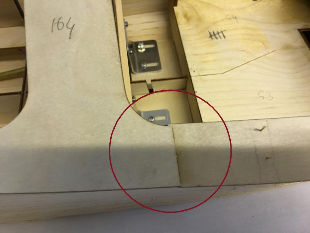
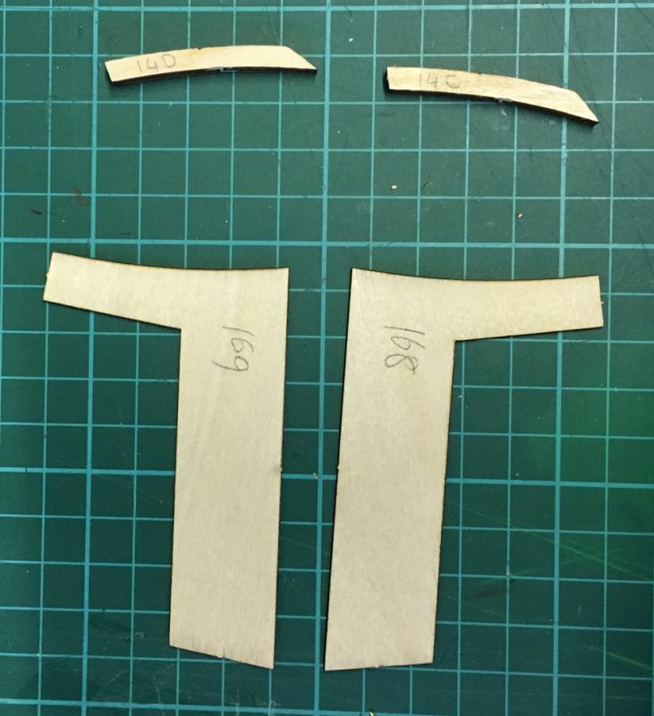
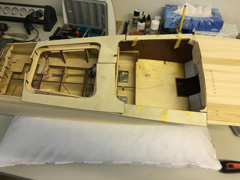
Hi Carl, 14C and 14D are meant to support parts 168 and 169 with glue. These parts are fixed. According to the instructions, the removable part (actually it is the engine lid) is positioned between them. In the photo below, you can see 168 and 169 on the sides and the lid (which now includes 170 and 171) in the middle: This is the view when the lid is removed (here note that the lid is sitting on the 2 wooden "hooks" inside). The red drawing on the left indicates where the 14C would have occupied if it had been installed as in the instructions (same on the other side). But in that case it is impossible to place the lid anymore. See also the red lines I have drawn on the instructions: So my solution was to chop off 14C and 14D short enough to stop preventing the lid and long enough to support the side pieces.

- 414 replies
-
- 8
-
-
- riva aquarama
- amati
- (and 2 more)
-
END of BUILD DAY 17. 4 hours today. 59 hours into build in total. Time is up for today. I will glue the mahogany pieces tomorrow. Thanks for watching.
- 414 replies
-
- 5
-
-
- riva aquarama
- amati
- (and 2 more)
-
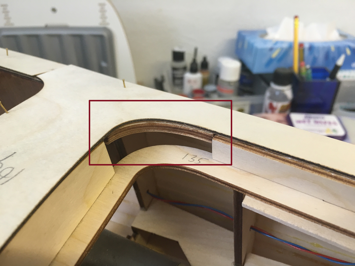
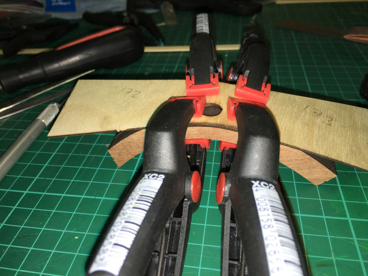
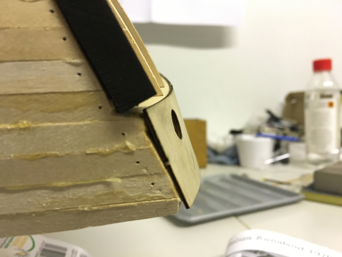
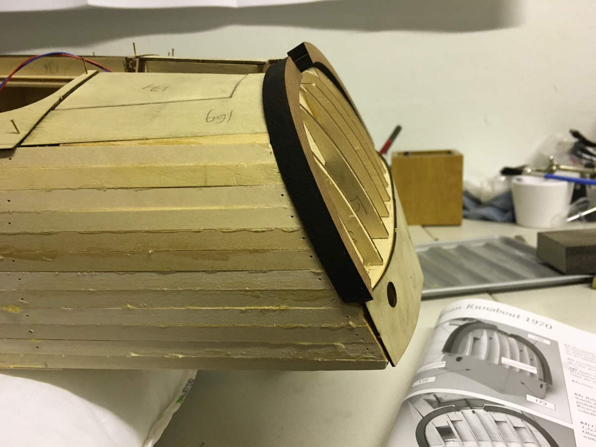
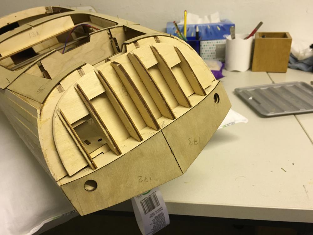
Coverings at the stern. The instructions call for trimming the ends of the thick mahogany arcs with a file to fit the flow of the stern (note the file symbols on the instructions). This sounds virtually unpractical to me since the piece is really thick and there is quite a lot to get rid of. Hence, I used a combination of saw, file, sandpaper, and knife to get the desired result: Bending the veneer parts on the lower part to fit easily: Veneers in place: This is why the mahogany arcs need trimming: Trimmed: And dry fitted to place:


- 414 replies
-
- 8
-
-
- riva aquarama
- amati
- (and 2 more)
-
The side pieces for some reason extend to outside a little bit. This also shows in the instructions. They will probably be trimmed later, since in the instruction manual the later pages show so.
- 414 replies
-
- 7
-
-
- riva aquarama
- amati
- (and 2 more)
-
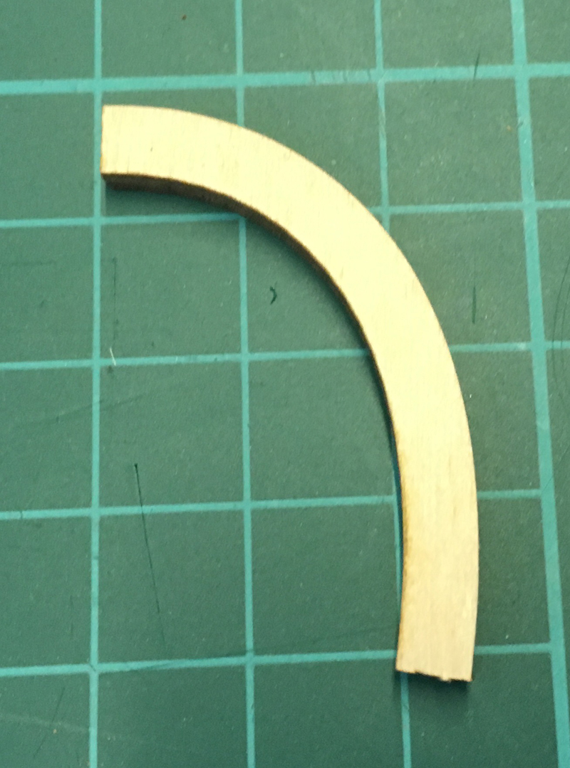
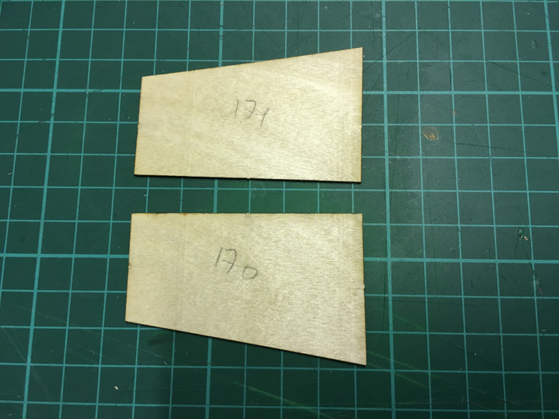
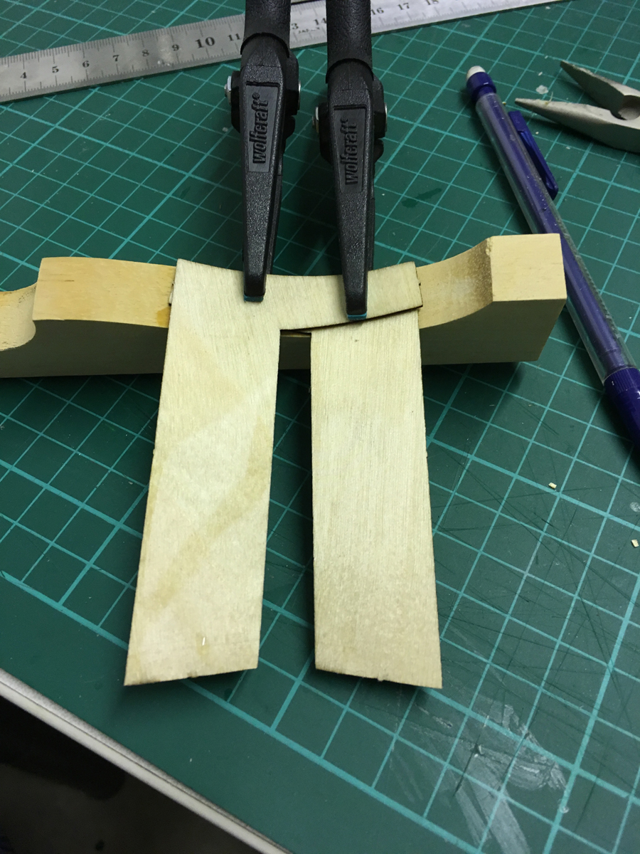
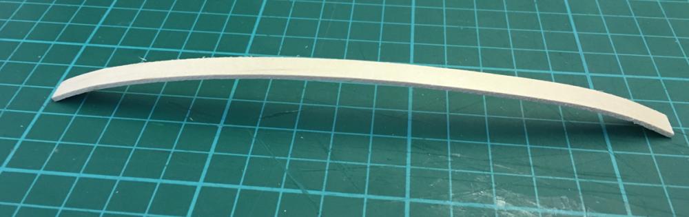
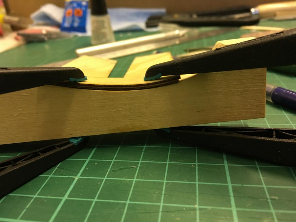
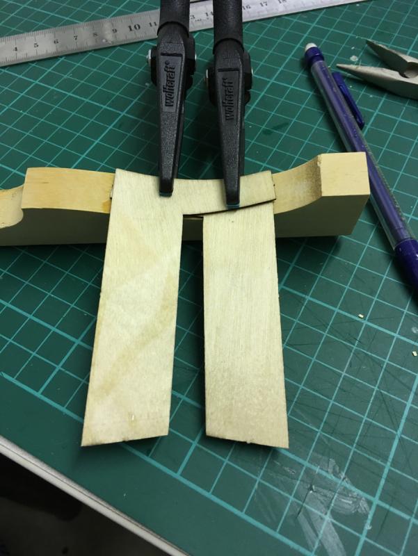
But before gluing, these two parts have to be curved a little in order to fit nicely:

- 414 replies
-
- 8
-
-
- riva aquarama
- amati
- (and 2 more)
-
Here I noticed a problem. Check the following 2 photos where I show the "removable" section. In the first photo it is out of its slot and in the second photo it is in place. Photo 1: Photo 2: Parts 168 and 169 are supposed to cover the open area on the left and right side of this removable part while parts 14C and 14D are to be glued on either sides to support them. However if you make the mistake of gluing the parts 14C and 14D (like I did - just look at the glue stains), there is no way to place the removable part anymore. Check from this photo how it would have blocked the removable section from placing to its slot: So I had to cut them short enough so that they won't block the removable section but still support the parts 168 and 169:

- 414 replies
-
- 8
-
-
- riva aquarama
- amati
- (and 2 more)
-
Dry fitting revealed that the thin "tail" at the back seems to require more critical positioning: Some edges overlap slightly. I'll have to trim them a bit (better leave some gap instead of overlap, since this is only the first planking): Parts 168 and 169. The parts 14C and 14D will be supporting them:
- 414 replies
-
- 9
-
-
- riva aquarama
- amati
- (and 2 more)
-
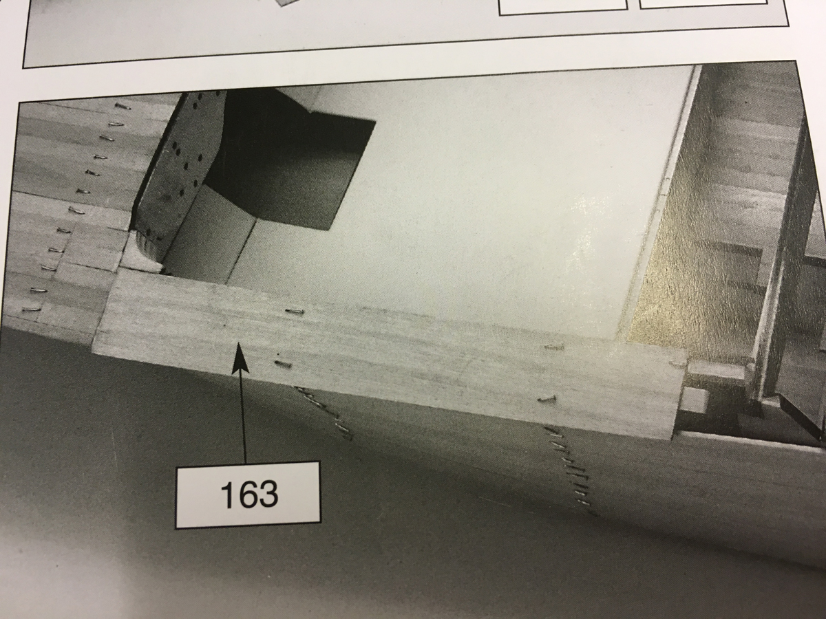
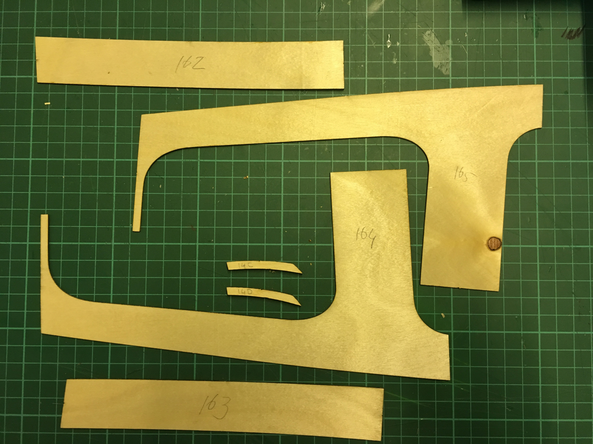
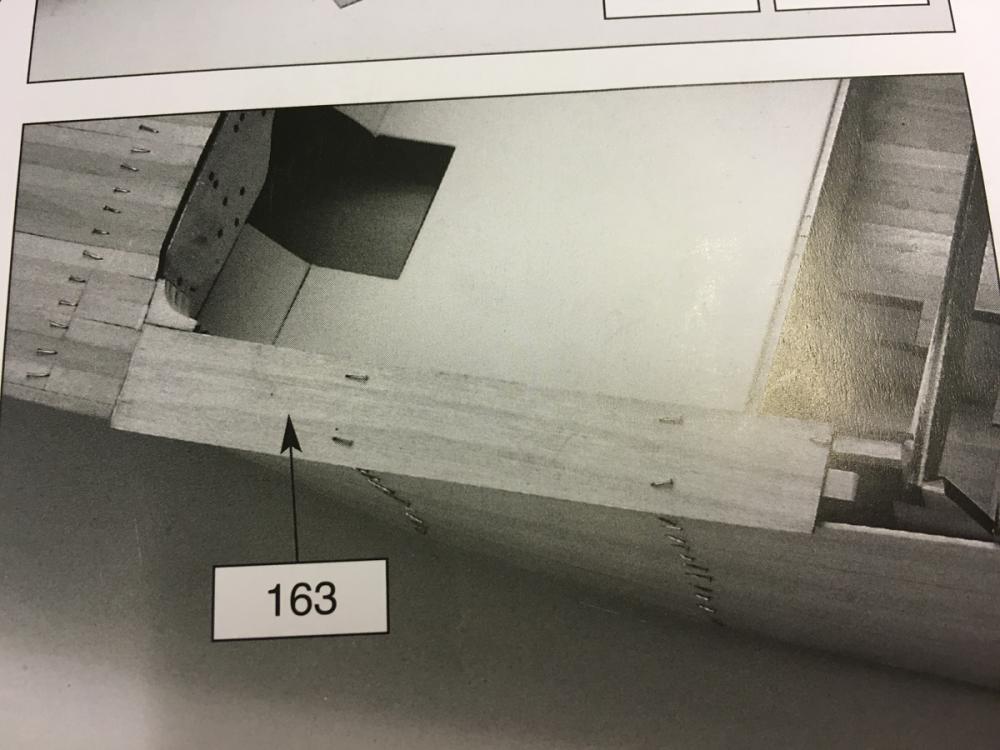
Rest of the 1st deck planking is mostly made of veneer sheets, such as these: Dry fit looks like this: Parts 162 and 163 require small support pieces on either end cut from planking strips:

- 414 replies
-
- 8
-
-
- riva aquarama
- amati
- (and 2 more)
-
Front deck complete. The excess planks on the edges will be trimmed once the glue has dried.
- 414 replies
-
- 7
-
-
- riva aquarama
- amati
- (and 2 more)
-
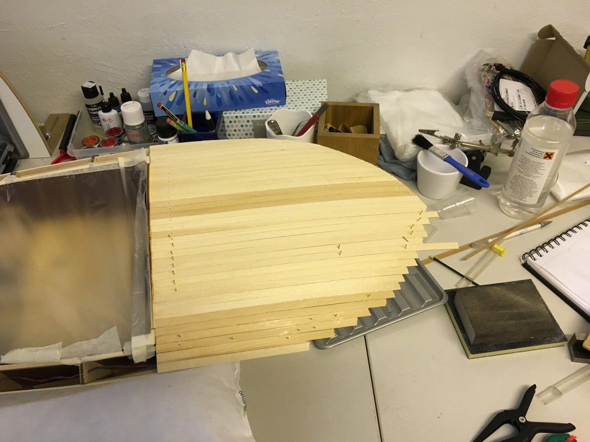
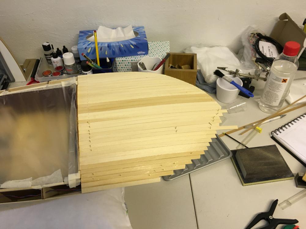
BUILD DAY 17. DECK PLANKING CONTINUED. Today I continue with 1st layer of deck planking. First the right half of the front deck. There are no straight lines in this beauty and the front deck is no exception. It is necessary to bend the stripes a little, even though they look like straight in the photos.
- 414 replies
-
- 5
-
-
- riva aquarama
- amati
- (and 2 more)
-
I am thinking of filling the gaps with epoxy from inside, after the second planking. In this case the second planking would have much smaller hole around the shafts.
- 414 replies
-
- 4
-
-
- riva aquarama
- amati
- (and 2 more)
-
END BUILD DAY 16. 4 hour today. 55 hours into build in total. This is the status after today. Thanks for watching.
- 414 replies
-
- 9
-
-
- riva aquarama
- amati
- (and 2 more)
-
Left part of the front deck 1st planking complete. It feels weird that the below the deck is completely hidden. There will be only a small part of it visible through the cockpit when the model has been completed.
- 414 replies
-
- 8
-
-
- riva aquarama
- amati
- (and 2 more)