aydingocer
-
Posts
916 -
Joined
-
Last visited
Content Type
Profiles
Forums
Gallery
Events
Everything posted by aydingocer
-
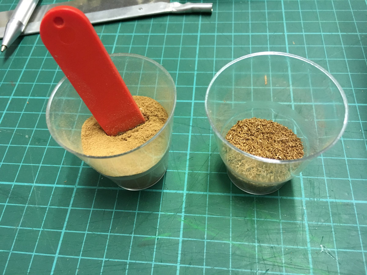
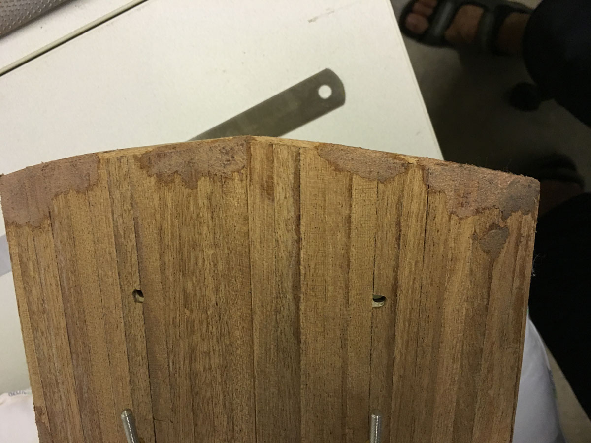
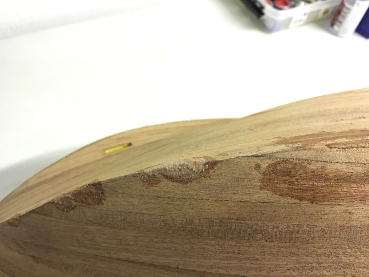
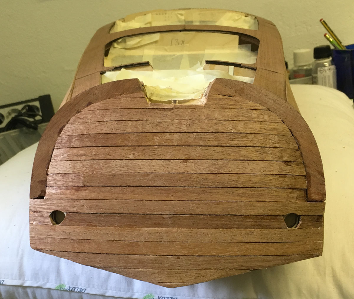
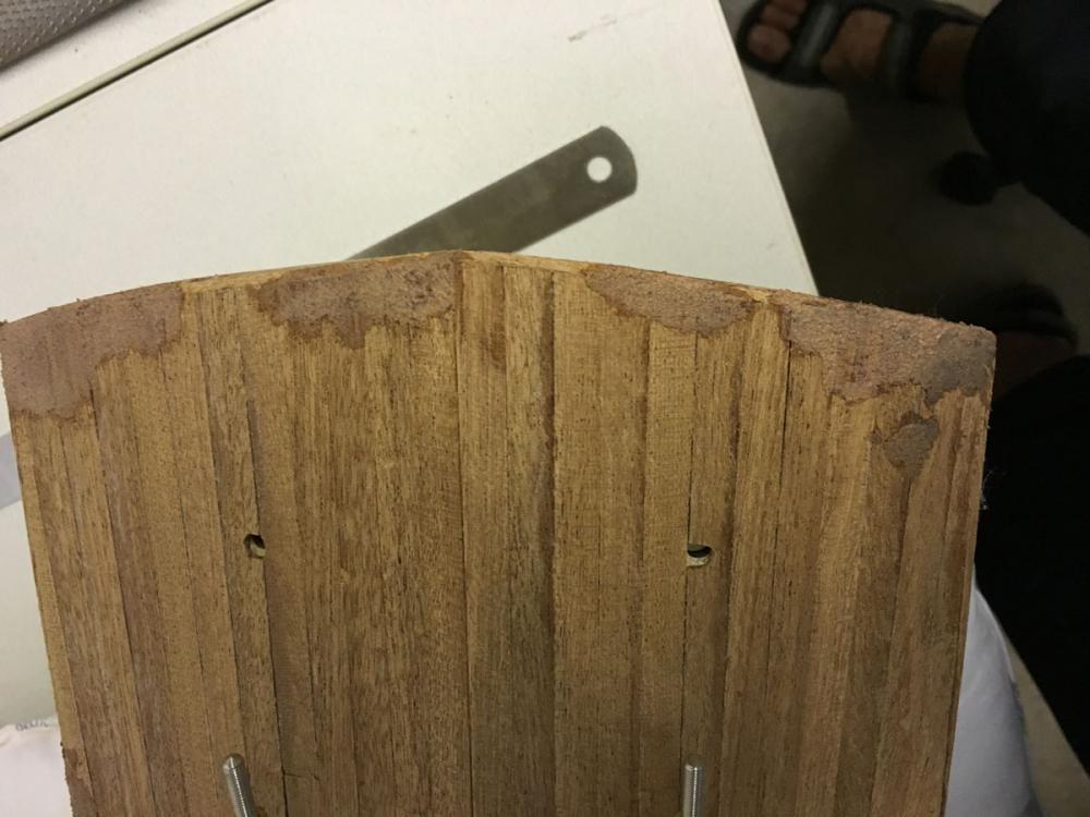
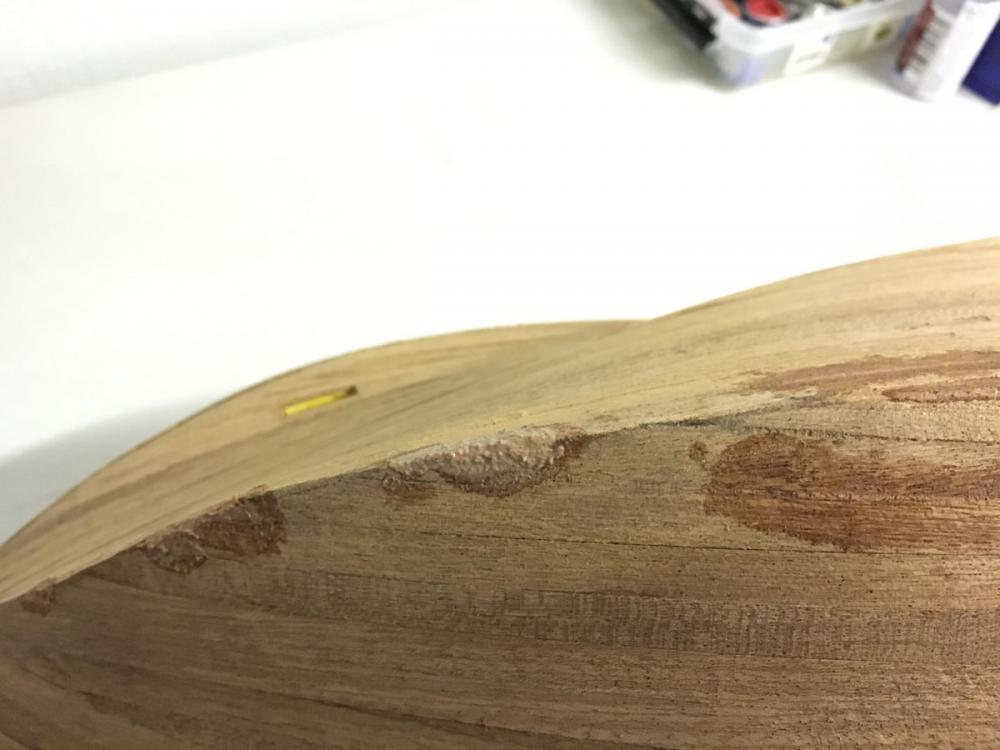
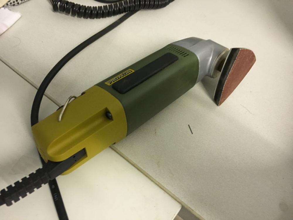
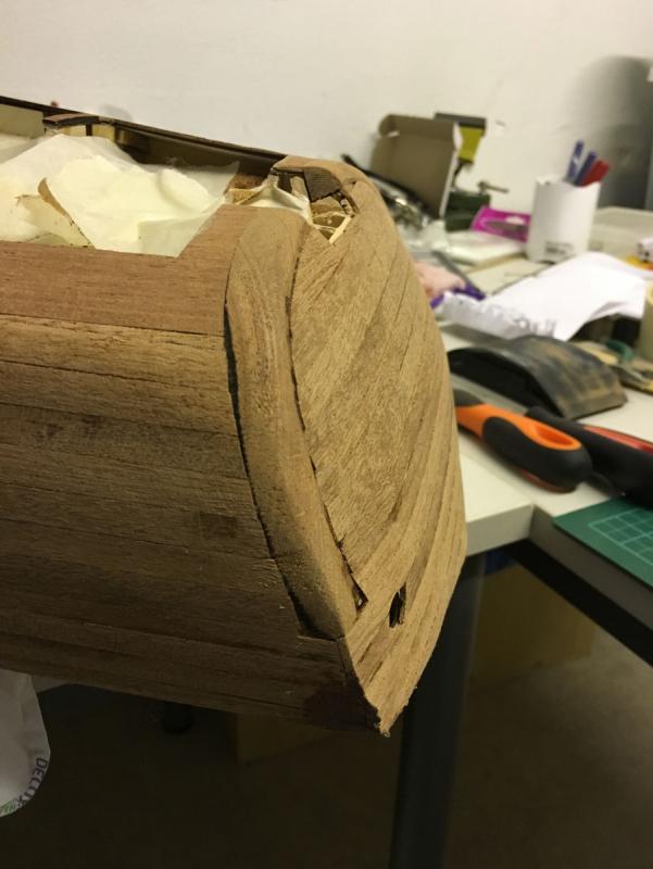
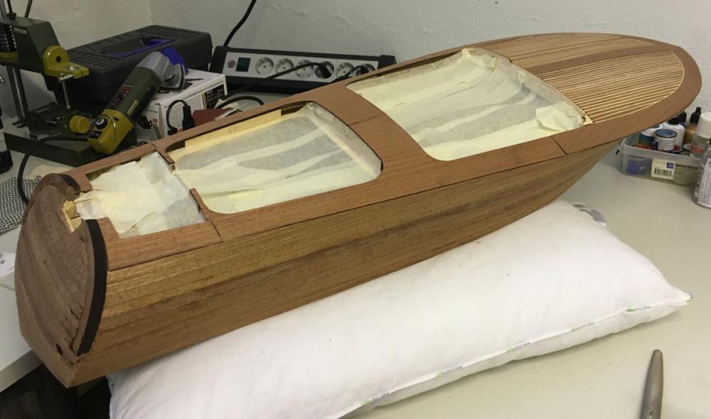
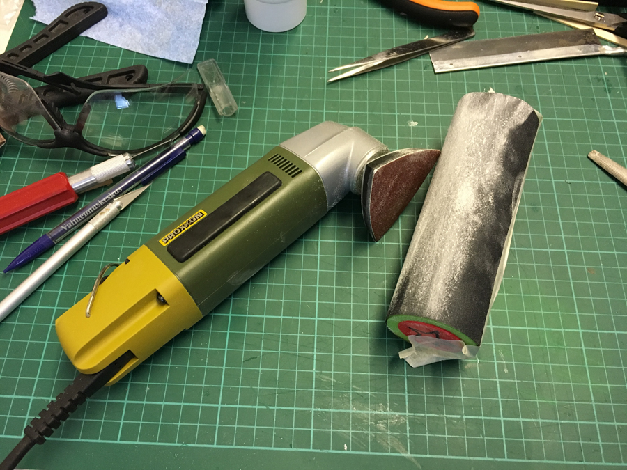
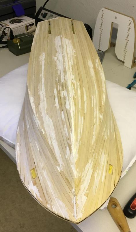
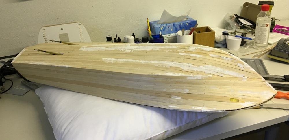
 Build day 28 - Sanding. 3 hours today. 98 hours into build in total. Sanding finally started today. I spent altogether 3 hours: - Rasping and shaping the rear arc moulds, - first coarse sanding of the hull (not the deck, yet) using 80 grit paper with random orbit sander. - first filling of the gaps with sand dust / glue mix I had promised to post some photos during this dusty job. Here are some of them. First, I rounded the arcs with a rasp (check a few photos above to see their initial shape). The dark parts adjacent to the planks are not gaps, but laser burn marks. I will cover them with the sand dust filling as well: This Proxxon random orbit sander is my best friend in these days: Collected plenty of sand dust on the way. Left: sand dust. Right: rasp dust (for rough filling): After 3 hours of sanding with Proxxon, the hull looks smoother and the gaps have been revealed and therefore I thought it is time to make the first filling of the gaps. The paste I prepared with sand dust and white glue/water mix is quite thin, therefore I will need to repeat the filling process. This makes the progress slower compared to a thicker paste but I guess the result will be worth it. Here are some fillings. I will continue tomorrow with more fillings and corrections before moving to next sanding sequence. Thanks for watching! /Aydin
- 414 replies
-
- 8
-

-
- riva aquarama
- amati
- (and 2 more)
-
First of all, thanks everyone for the encouraging comments. Hi Per, Yes, deck will be covered with fiber-glass / epoxy solution just like the entire hull. I will also put Hempel yacht sealer in the cockpit and the engine area from inside. And then, paint where required (yes, unfortunately some part of this beautiful mahogany will have to be covered with paint, especially below the waterline) . So, that's the plan.
- 414 replies
-
- 3
-
-
- riva aquarama
- amati
- (and 2 more)
-
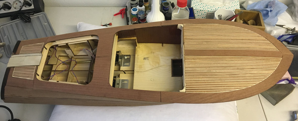
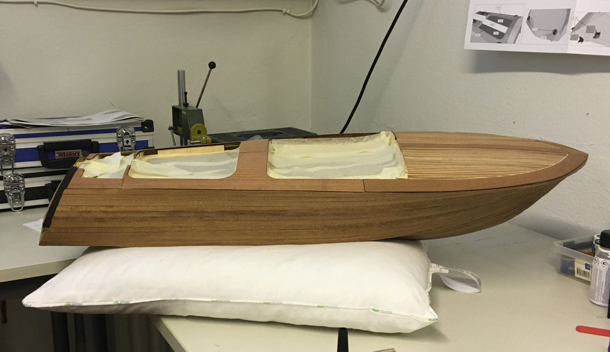
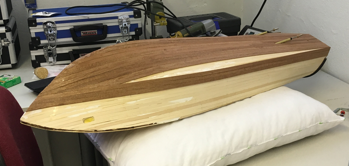
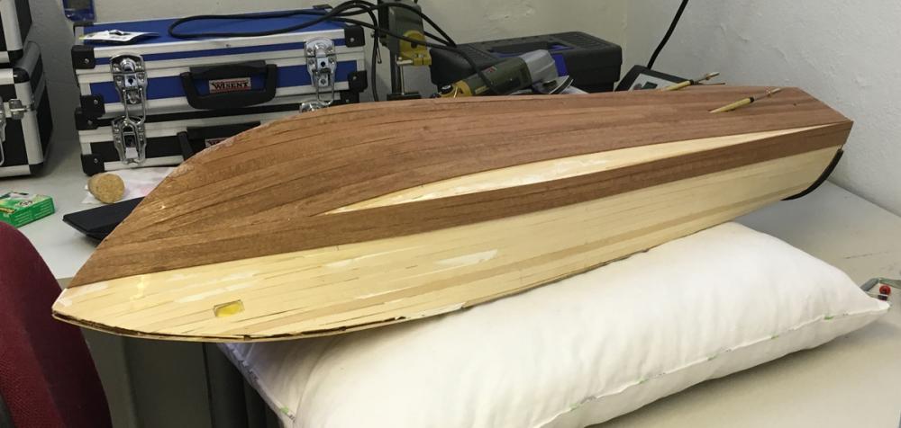
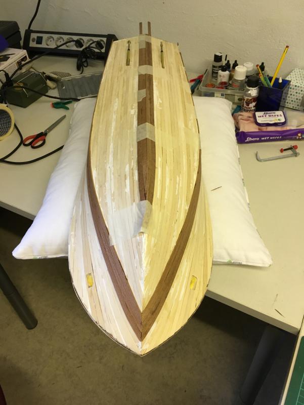
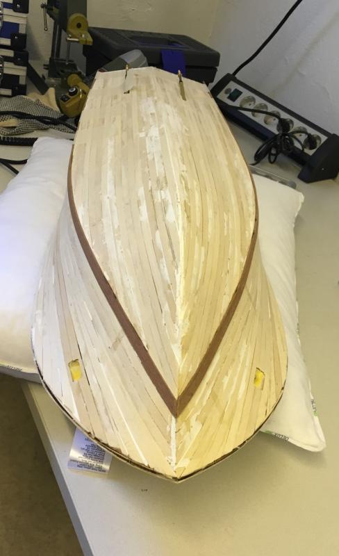
Below I am adding a series of photos showing the final planking process and the current status before starting smoothing work. I will try to post some photos during sanding when I can. Thank you for watching and see you later! Aydin


- 414 replies
-
- 9
-
-
- riva aquarama
- amati
- (and 2 more)
-
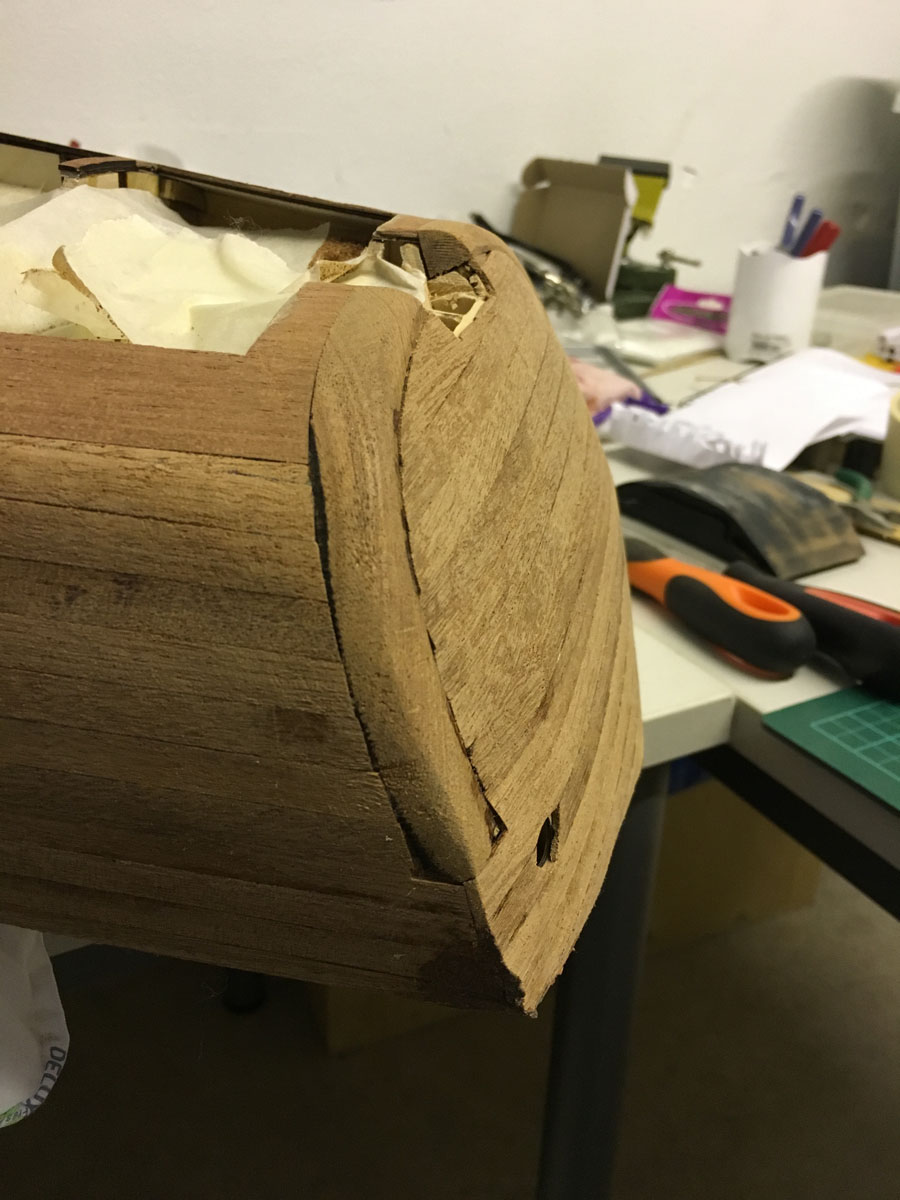
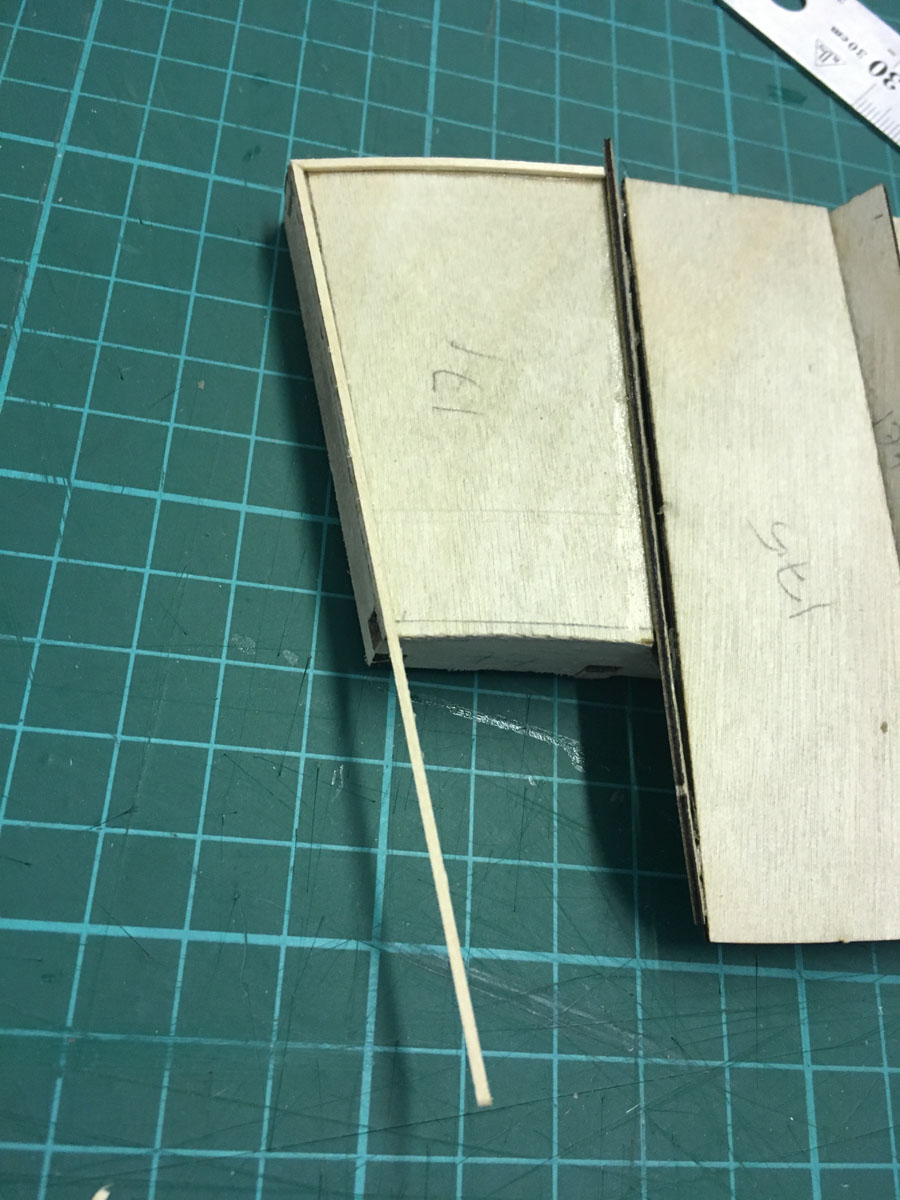
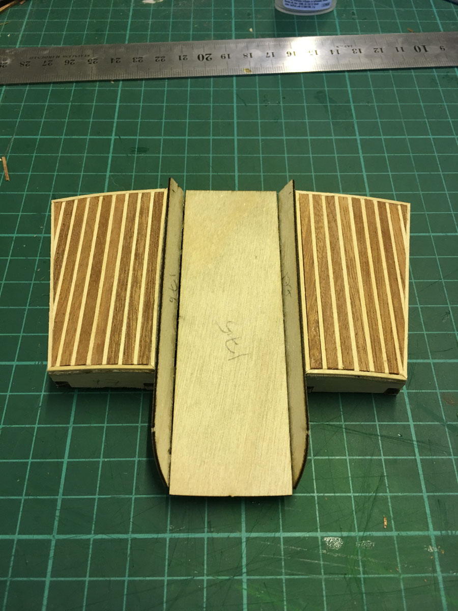
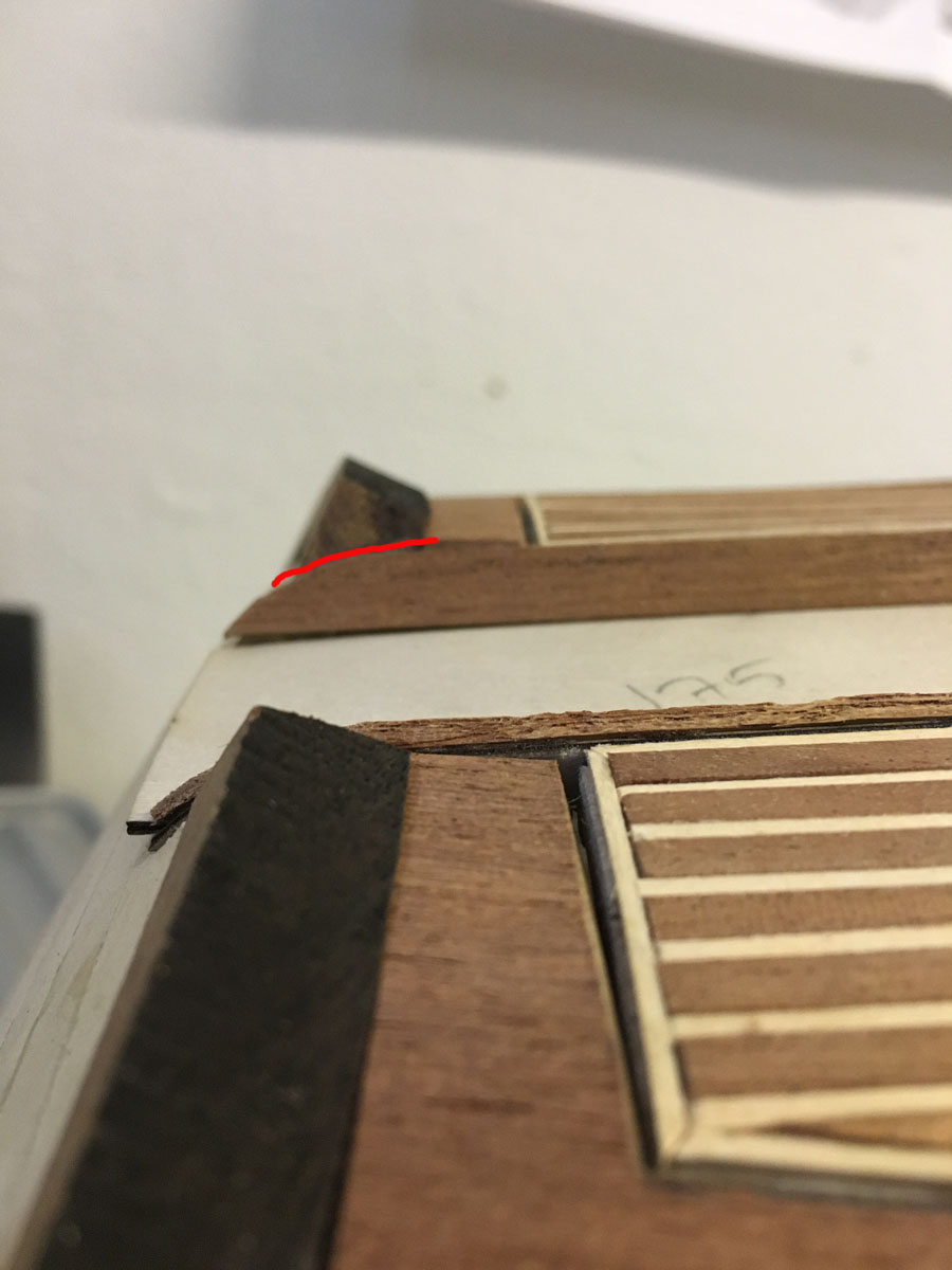
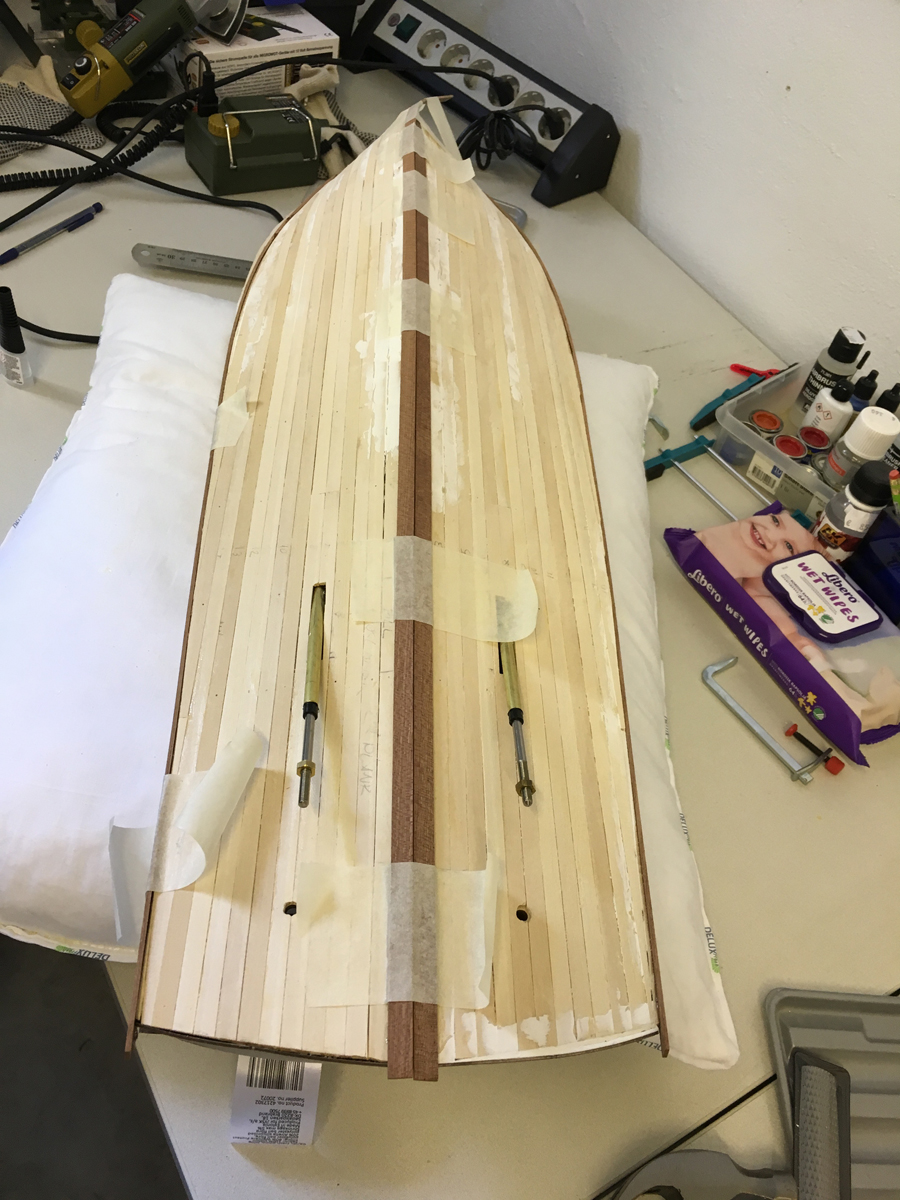
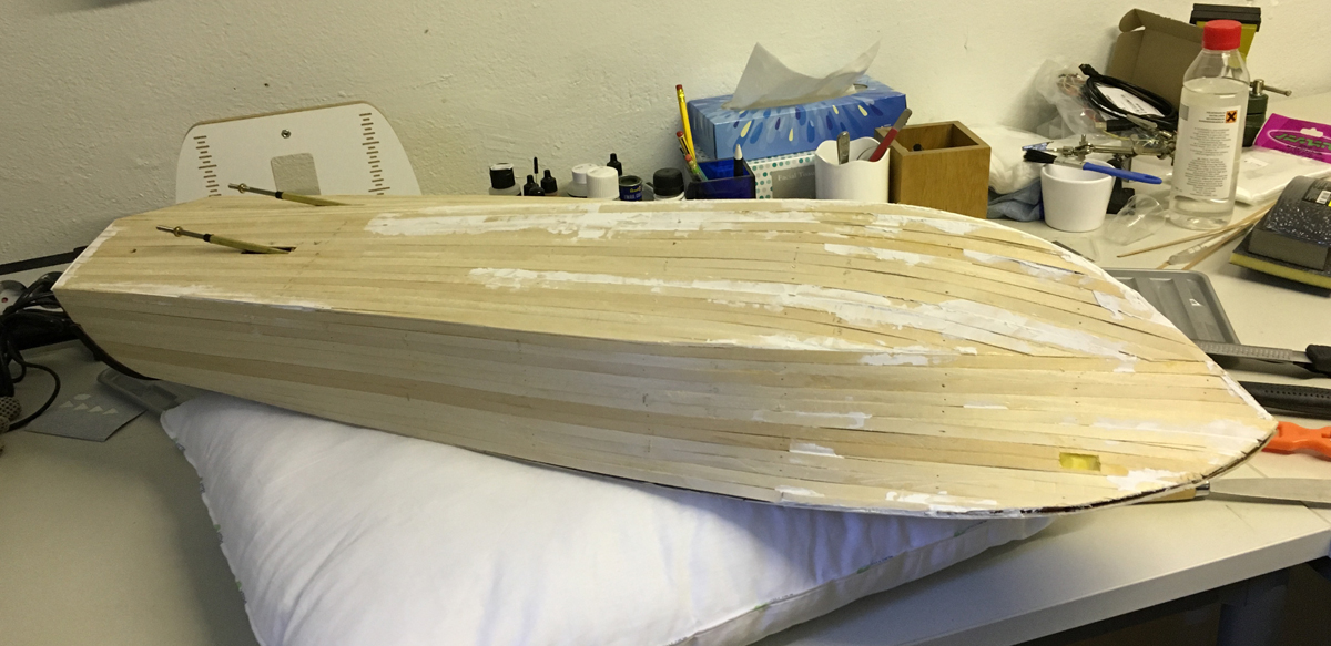
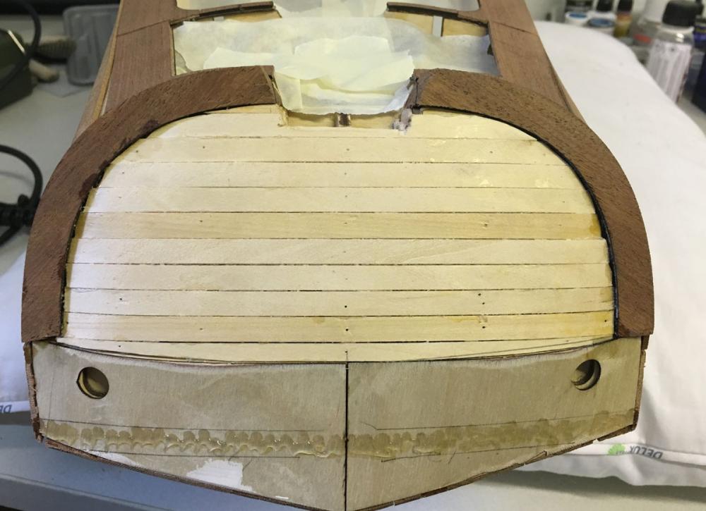
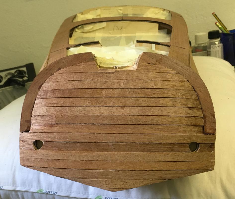
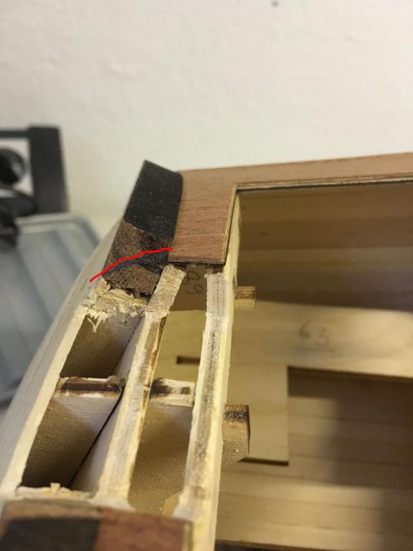
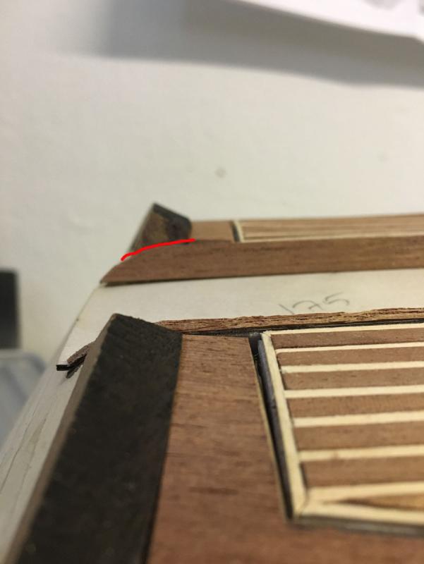
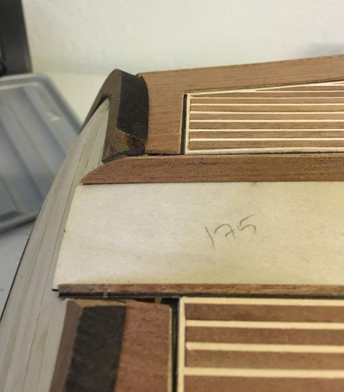
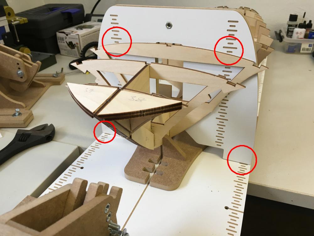
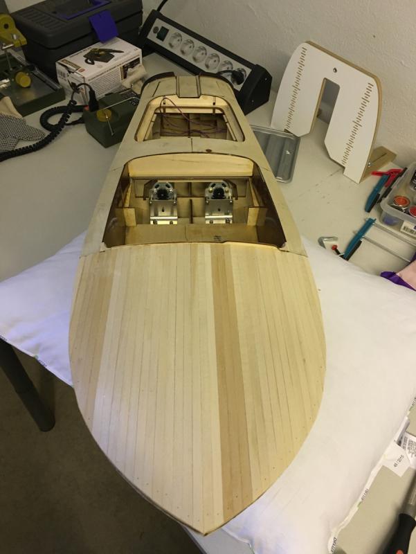
Build day 26 & 27. 2nd planking complete. 5 hours in both days. 95 hours into build in total. I spent some 5 hours in last two days and the 2nd layer of planking seems to be complete now (hopefully). Next few days of work will surely be the dustiest part of the entire project: rasping --> filing --> sanding, sanding, sanding... , filling the gaps, sanding sanding again... With this I am hoping to get rid of the impurities on the surface and get the model as smooth as possible. The heaviest part of this "smoothing" work will no doubt be rounding of the two "mould arcs" in the back top. These 10mm thick mahogany arcs need to be shaped flush on the edges with all the other deck components which they are adjacent to. Here are some examples of how much they have to be rasped and filed (tried to indicate the pattern with red lines):
- 414 replies
-
- 6
-
-
- riva aquarama
- amati
- (and 2 more)
-
There are several models of this boat (1965, 1972 etc), probably the difference is because of that. The kit (which is claimed to be museum quality by the manufacturer) is supplied with mahogany/lime for this purpose. I think it is the 1965 model. Anyway, a quick search in Google returned this Riva Collection museum in Italy: http://collection.bellininautica.it/en/museum/collection/ There are Aquarama boats in that museum with similar planking as in this kit. /Aydin
- 414 replies
-
- 7
-
-
- riva aquarama
- amati
- (and 2 more)
-
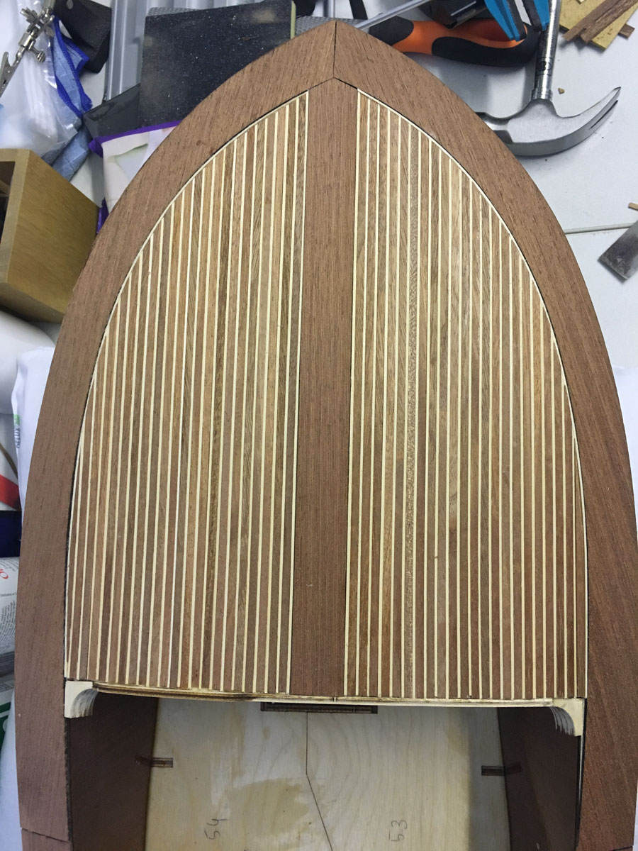
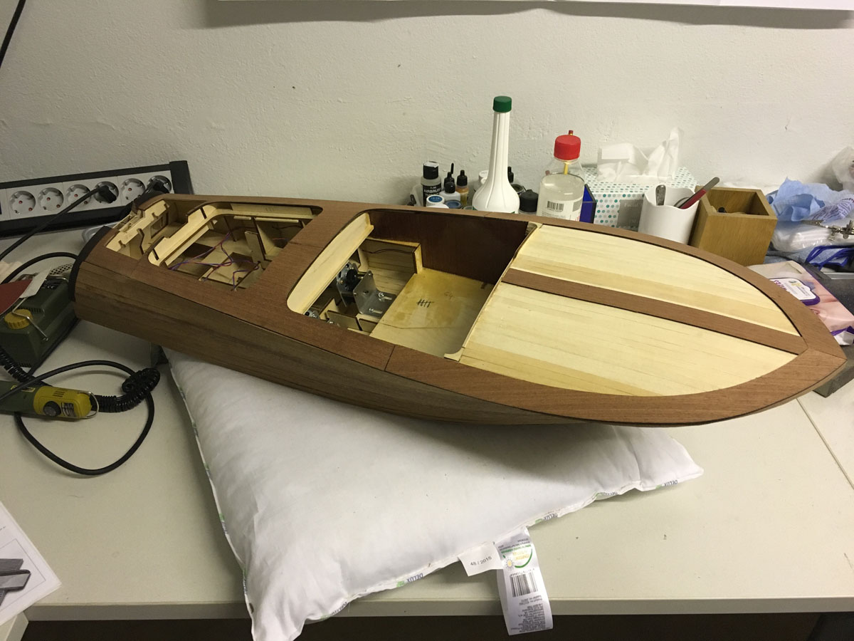
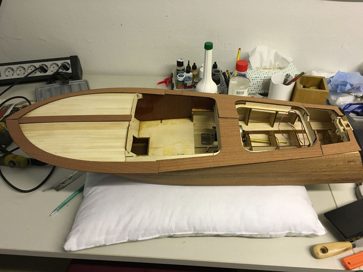
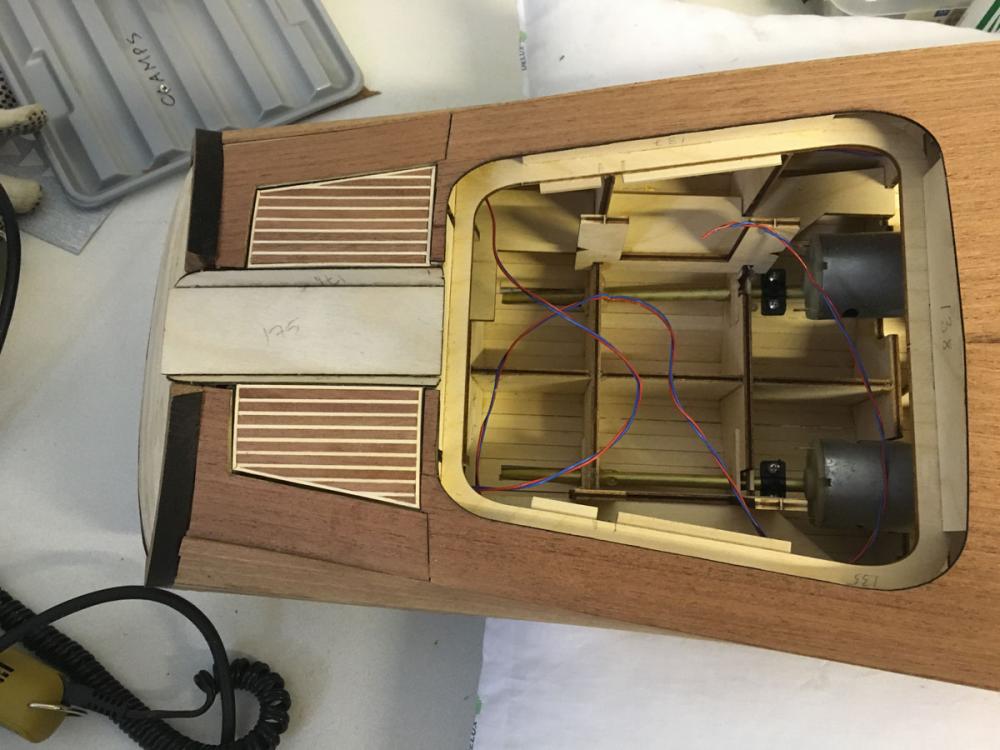
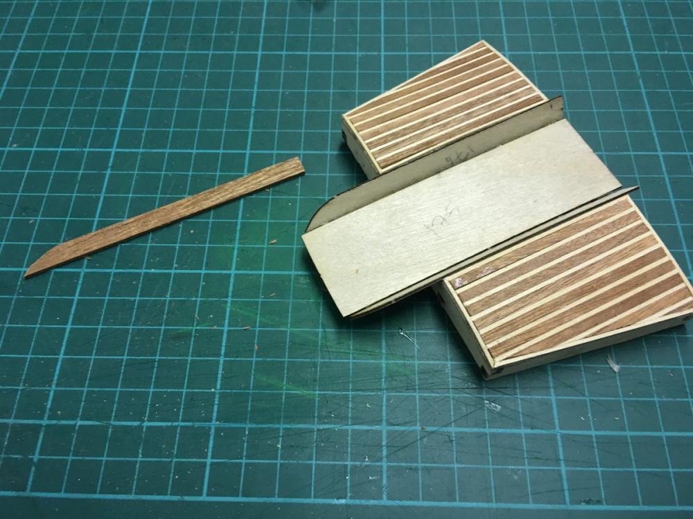
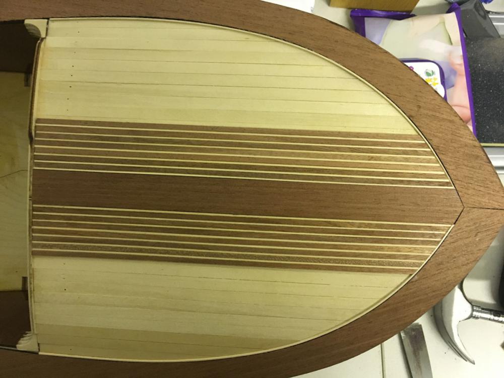
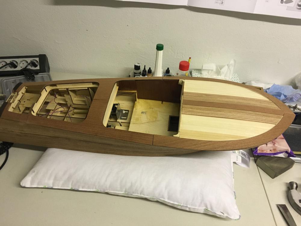
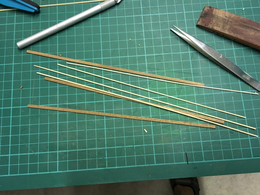
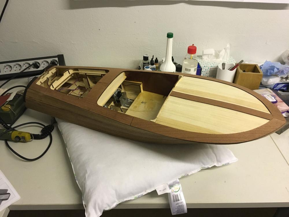
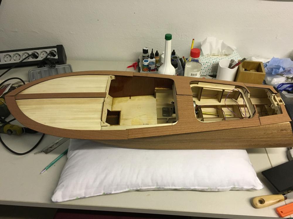
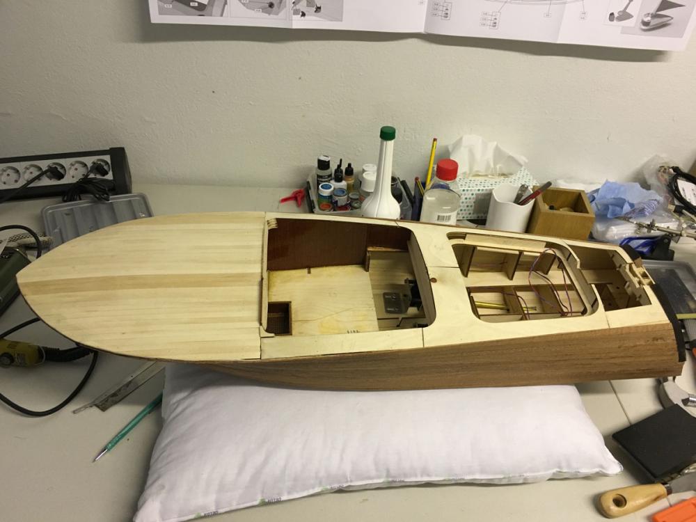
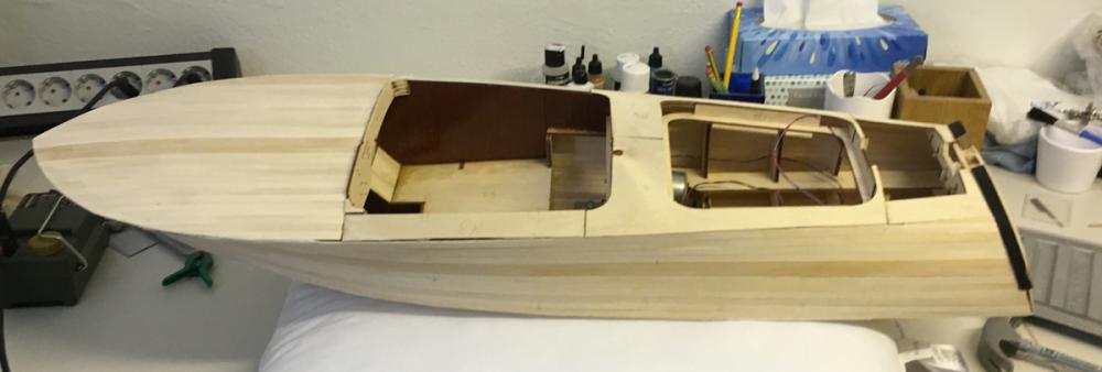
Build day 25 5 hours today. 90 hours into build in total. Today I had more spare time with my Riva. I glued the upper deck plank sheets and was even able to proceed on the front deck planking strips. After today it looks like my Riva has started to reveal its beauty, though slowly, but surely Upper deck mahogany sheets in place. Some of the gaps between the pieces were unavoidable, for example those on the side of the cockpit. I opted to leave equal gap on the other side for the sake of symmetry. Part of those gaps will be covered with ornaments and upholstery. Others, I will figure out either by filling with sawdust or just leaving like that and letting the varnish give its look: Deck strips, 1x1mm lime and 1x3mm mahogany, to be glued in alternating turns. The same pattern will be used in front deck as shown as well as on the engine lid at the back: Proceeding with the front deck planking. The ends on the cockpit side will be covered later with another mahogany sheet therefore the strips do not have to align perfectly on that side: This is the status at the end of the day: Thanks for watching. /Aydin
- 414 replies
-
- 10
-
-
- riva aquarama
- amati
- (and 2 more)
-
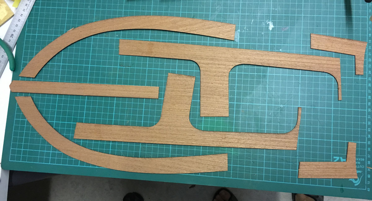
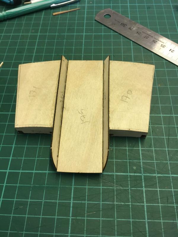
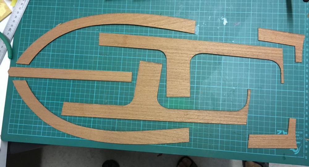
Deck 2nd planking. Most of it is uses 1mm thick mahogany sheets. Rest will be done using 1x1mm lime and 1x3mm mahogany strips. The parts: Before: After dry-fit:
- 414 replies
-
- 10
-
-
- riva aquarama
- amati
- (and 2 more)
-
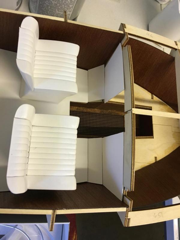
Actually the second photo above does not have the faux leather on yet. They are just pure plastic seats right out of the box. That's why I will still give a try how they would look after I cover them with my leather sheets. Chances are I just give up the idea if it won't look good and just use them like that instead. I may also use some paint to color the sides to turquoise like in the upper photo.
- 414 replies
-
- 3
-
-
- riva aquarama
- amati
- (and 2 more)
-
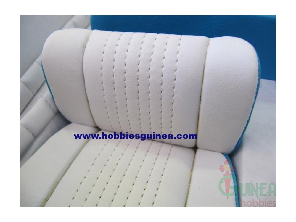
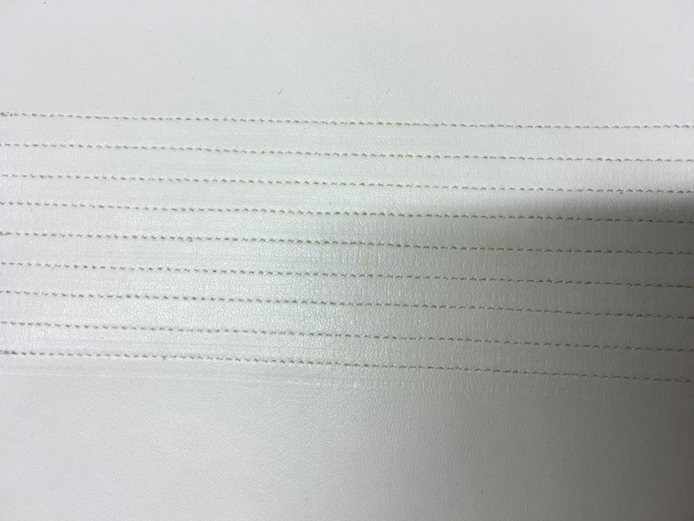
Hi Carl, The "stitch lines" on the seats are 6mm apart from each other (see photos). 1st photo, as I posted earlier, belongs to the earlier version of the kit, where the seats are actually stitched. The second photo is what the contemporary kit (i.e. mine) contains as seats. The seats that come with previous versions of the kit (photo credits hobbiesguinea.com): Seats in my kit: The stitch sizes (i.e. around 1mm) was the smallest size possible on faux leather using a special nail (we actually went to a tailor's supply shop together with the tailor to buy that sawing machine nail, can you believe ). I think it has even better looks-to-scale than the older seats in the first photo.
- 414 replies
-
- 6
-
-
- riva aquarama
- amati
- (and 2 more)
-
Wow, looks great! Maybe I will pay a tribute visit to Venice after I have completed
- 414 replies
-
- 4
-
-
- riva aquarama
- amati
- (and 2 more)
-
BUILD DAY 24. Back from vacation and today I had some 2 hours to spend on my Riva. I finished the remaining 2nd plankings on the body. Next I will continue with deck's 2nd planking. Here is also a teaser for your eyes, to be used on my seats. As I told earlier the seats which come with the new version is plastic (as opposed to the earlier editions which were apparently fabric covered). I have been looking around how to make them look better. As a try I bought a few (A4 size) faux leather sheets and asked a local tailor to make the stitches for me (by local I mean a tailor in my parents' neighbourhood in Turkey). He did an excellent job with making fake stitches. The stitches are 6mm apart from each other and about 1mm in length. I have no exact plan yet on how to implement them to the seats. I still have a lot of tasks to do before it comes to that. Here is how it looks: 2 hours today. 85 hours into build in total.
- 414 replies
-
- 9
-
-
- riva aquarama
- amati
- (and 2 more)
-
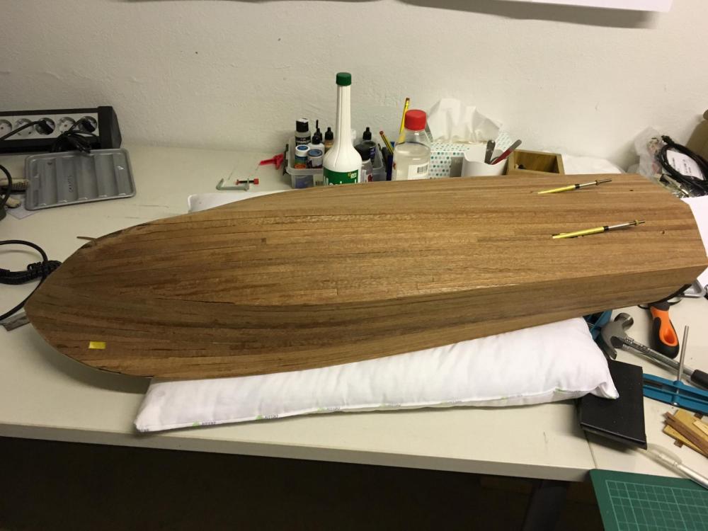
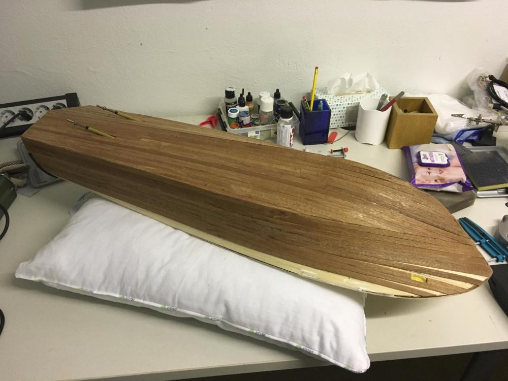
BUILD DAY 23. 4 hours in two days. 83 hours into build in total. Almost finished with 2nd planking of the bottom. Tomorrow I will be away for about 2 weeks of vacation, so no progress very soon. Thanks for watching.
- 414 replies
-
- 9
-
-
- riva aquarama
- amati
- (and 2 more)
-
Thanks for comments, Brian and Per. I have investigated several build logs in the radio control kit forums and epoxy resin + fibreglass seemed to be working fine, as you guys mentioned, if done properly. I will work on a few samples before I hit the first brush stroke on my Riva, sure.
- 414 replies
-
- 3
-
-
- riva aquarama
- amati
- (and 2 more)
-
Hi Don, I have used my build slip mainly for gluing the bulkheads and then mostly as a stand after that for planking. During planking I used a pillow which was making it easier for me (as I often intend to take the hull to my lap for close work). Buy anyway here are a few photos. On the first picture below you will see the screw holes at every 10cm intervals, on both sides of the base board. You also see the "panel" which is standing vertically. There are 2 "rails" on either side behind this panel. These rails are fixed to the panel (in other words, the white vertical panel and the two rails slide together on the base board). The rails have screws, which can be tightened/loosened using washers. While the screws are in the same hole the rails will allow the panel to move around 10cm back and forth. So, - as you will work with the next frame, you move the panel accordingly. - when the rails do not allow moving any further with the screws in the same hole, then you remove the screws, move the panel to the next location and put the screws to the next pair of holes. Second photo below shows how you use the measurements on the panels for reference: You can catch a few more photos in the early pages of my Riva Aquarama build log where the build slip is in action: http://modelshipworld.com/index.php/topic/13427-riva-aquarama-by-aydingocer-amati-radio-a-new-challenge-for-a-so-far-static-ship-builder/ Br; Aydin

-
Thanks a lot Mark! I think the diluting of the white glue with water is what was missing in my formula.
- 414 replies
-
- 4
-
-
- riva aquarama
- amati
- (and 2 more)
-
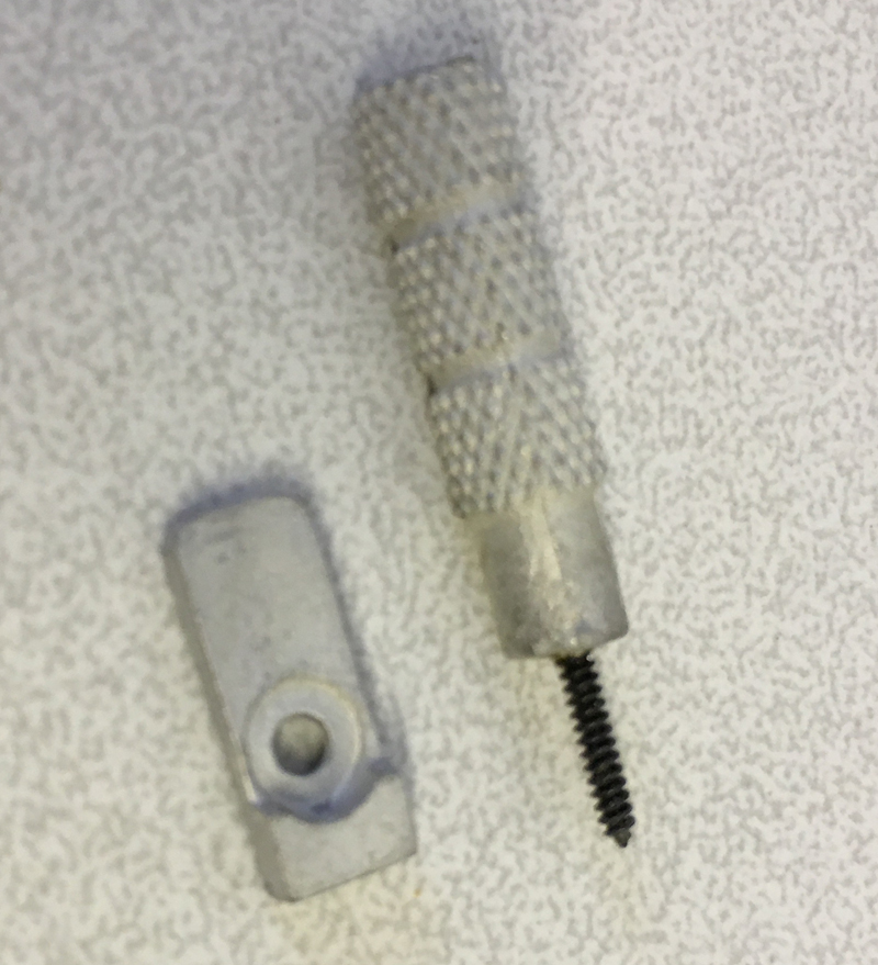
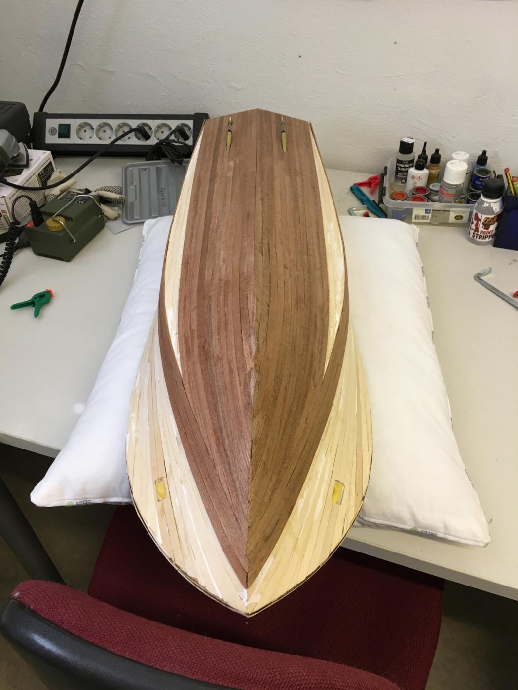
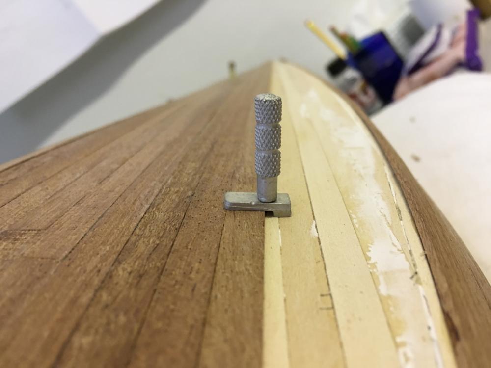
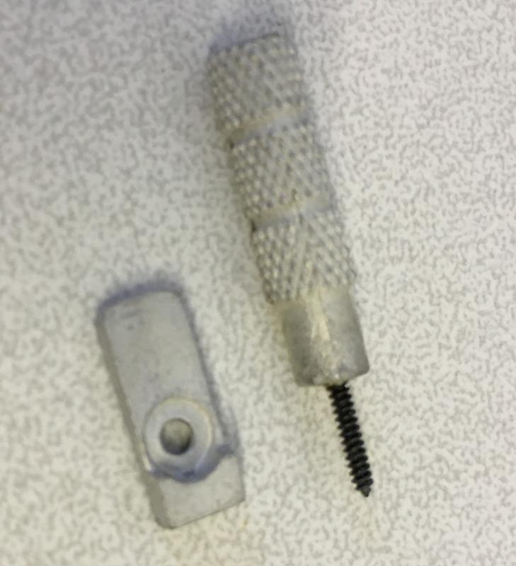
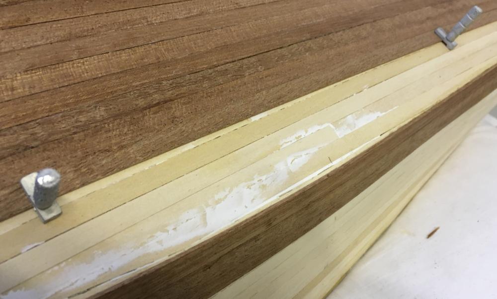
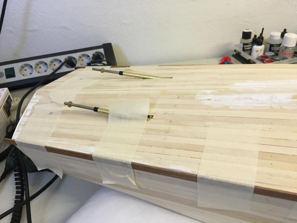
BUILD DAY 21-22. 8 hours in two days. 79 hours into build in total. Continuing with the second planking in these two days. No big surprises so far. The wood is extremely good quality which helps a lot. Here are some details: I have been using these special screws on some occasions where I tape or rubber band was not very helpful. These are the screws which I had mentioned in an earlier post, bought from Micro Mark web shop: This is the status at the end of the day. You will notice some impurities here and there, some of which I filled with self-made paste by mixing wood glue and mahogany dust (collected by filing a scrap mahogany strip). So far I have filled some of the gaps below the waterline which will be painted in white, therefore the color difference is not a problem. If it works colorwise fine as well, then I will use it in other parts. The bow will covered as well, using photo etched brass, therefore the color difference will not matter there either. By the way; if any of you experienced fellow members have any suggestion for how to fill the gaps seamlessly, I would be more than happy to hear. Thanks for watching.

- 414 replies
-
- 10
-
-
- riva aquarama
- amati
- (and 2 more)
-
Ah, yes, you mean the inside. For that I have in mind to use epoxy based sealer, such as Hempel 599, which is used in yachts.
- 414 replies
-
- 5
-
-
- riva aquarama
- amati
- (and 2 more)
-
Sure I will make several tests on scrap wood. You can't rush science... especially on a piece of art
- 414 replies
-
- 4
-
-
- riva aquarama
- amati
- (and 2 more)
-
I am planning to use fiberglass sheet with epoxy solution after I am done with planking, before assembling the ornaments. Here is a good 15 minute youtube tutorial which I think I will follow the instructions in:
- 414 replies
-
- 7
-
-
- riva aquarama
- amati
- (and 2 more)
-
END of BUILD DAY 20. 6,5 hours today. 71 hours into build in total. I managed to do sanding and plank altogether 10 strips today. Not bad. Here is the status below. Thanks for watching.
- 414 replies
-
- 8
-
-
- riva aquarama
- amati
- (and 2 more)
-
I avoid using nails for fixing on this stage, since the holes will be hard to conceal later. Instead I use masking tape (and a little bit more CA glue) to compensate.

- 414 replies
-
- 8
-
-
- riva aquarama
- amati
- (and 2 more)
-
Let the 2nd planing begin! Planking material: 1,5mm x 8mm mahogany (as opposed to 1,5mm x 7mm lime used in first planking). This is interesting as I would normally expect the 2nd planking strips to be thinner. These ones are as thick as the lime planks underneath. 2nd planking follows pretty much the same sequence as the first planking. Start with 1 strip from the center of the each side of the hull, then switch to the middle of the bottom, then continue in alternating turns.
- 414 replies
-
- 6
-
-
- riva aquarama
- amati
- (and 2 more)
-
BUILD DAY 20. 2nd PLANKING COMMENCES. Today I spent some 1-2 hours for sanding, after which I concluded that the surface is smooth enough for 2nd planking. My tools were Proxxon orbital sander with 180 grit paper and a sanding drum, same grit paper, self-made sanding drum from a pool toy (water gun). The latter has been a perfect tool with its soft cushion especially on the curvy surfaces: The hull is now ready for 2nd planking:
- 414 replies
-
- 7
-
-
- riva aquarama
- amati
- (and 2 more)
-
END of BUILD DAY 19. 4 hours today. 64,5 hours into build in total. Scraping is complete now and the boat is ready for sanding. This is the status at the end of day. Thanks for watching.
- 414 replies
-
- 10
-
-
- riva aquarama
- amati
- (and 2 more)