aydingocer
-
Posts
916 -
Joined
-
Last visited
Content Type
Profiles
Forums
Gallery
Events
Everything posted by aydingocer
-
 Thanks for the tip, Antony. It came in the right time as I was just about to order the brass propellers. In this case I will order the smaller size, since the main purpose of them will be for display pusposes.
- 414 replies
-
- 5
-

-
- riva aquarama
- amati
- (and 2 more)
-
First motor in place, after quite a bit of tricky turns and twists. It is topologically possible to insert, but you'll have to find the right movements .

- 414 replies
-
- 8
-
-
- riva aquarama
- amati
- (and 2 more)
-
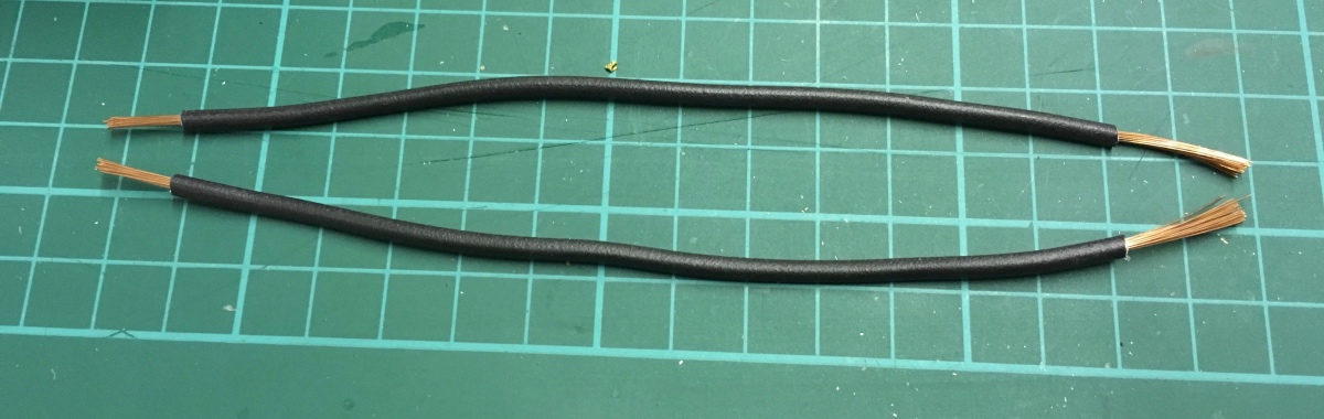
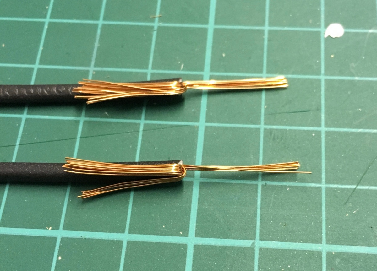
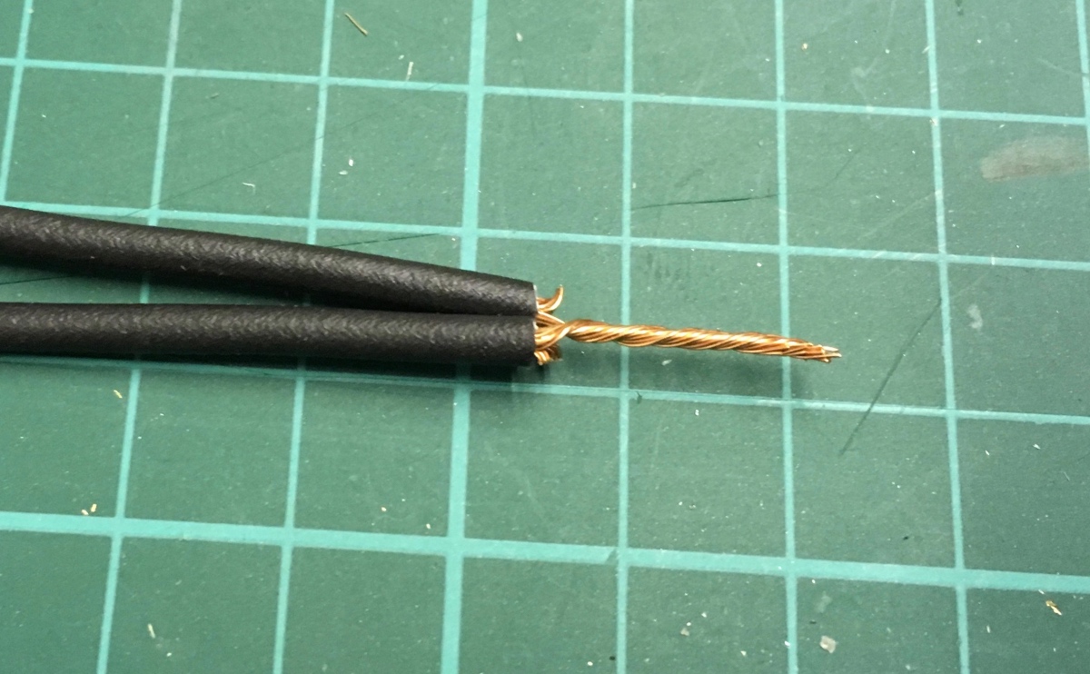
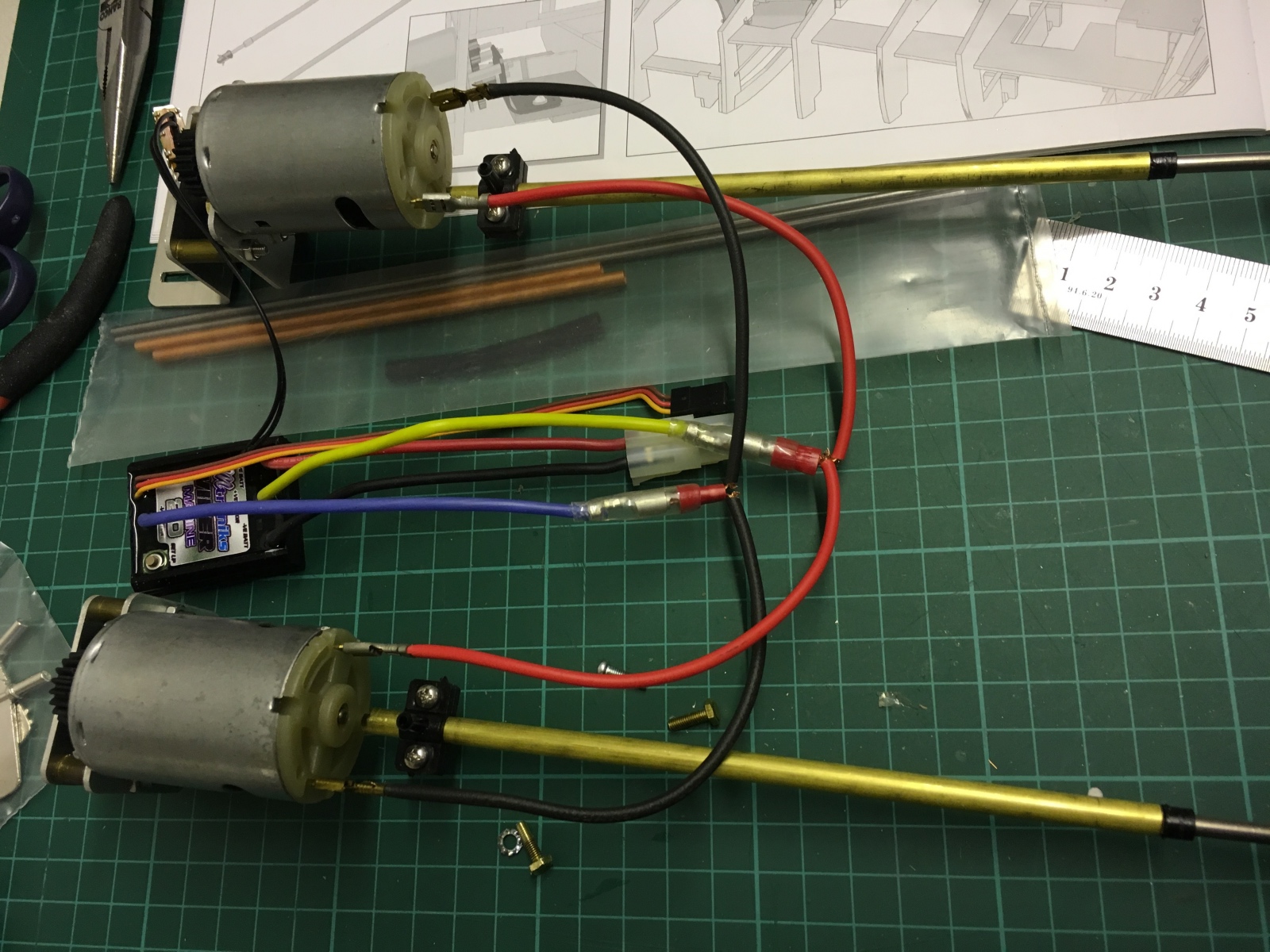
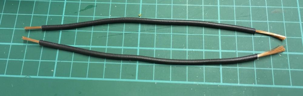
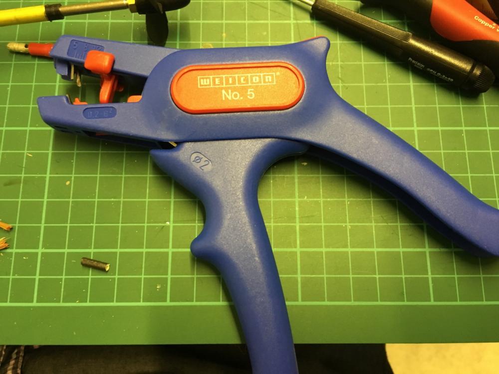
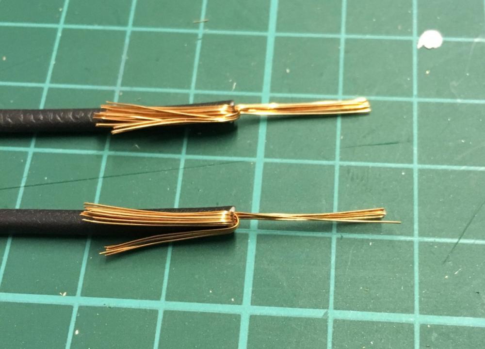
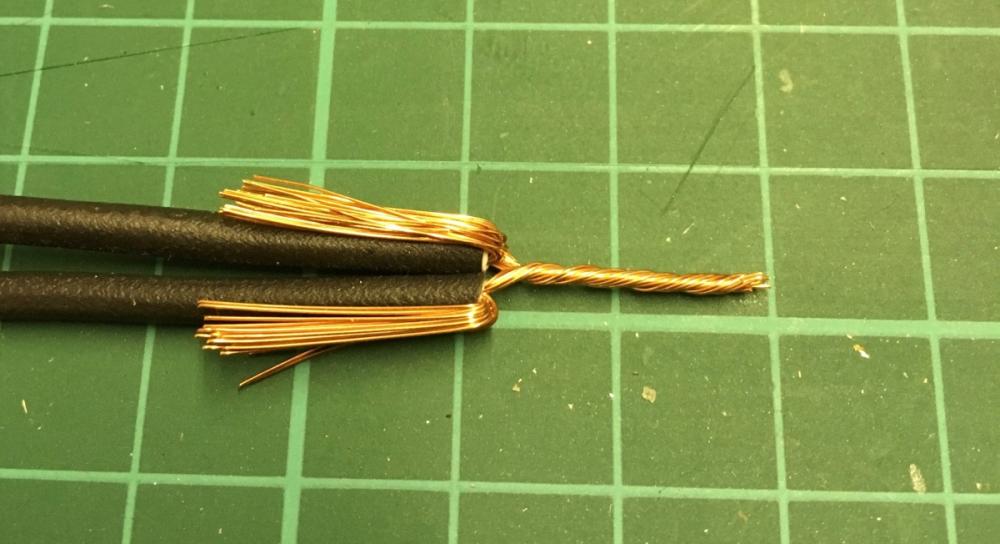
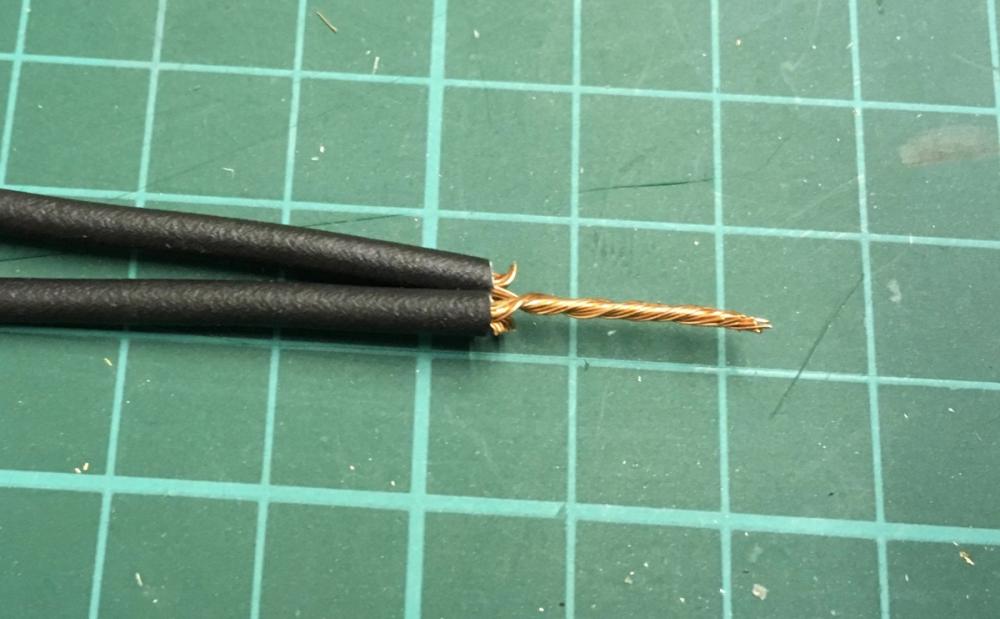
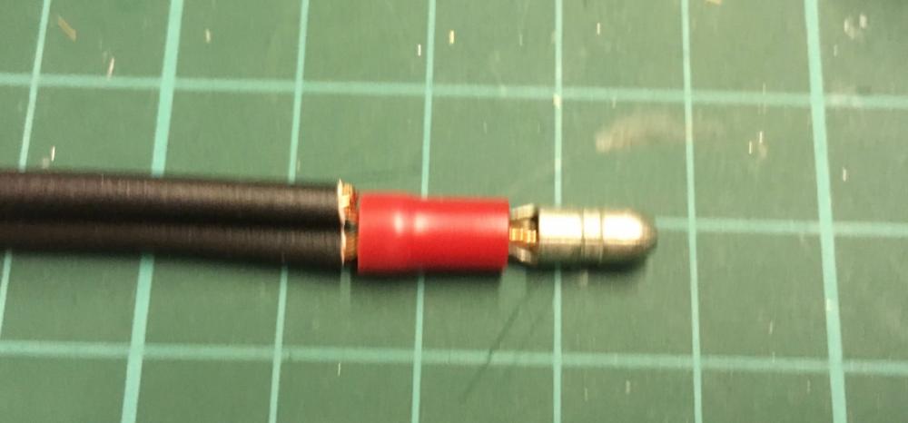
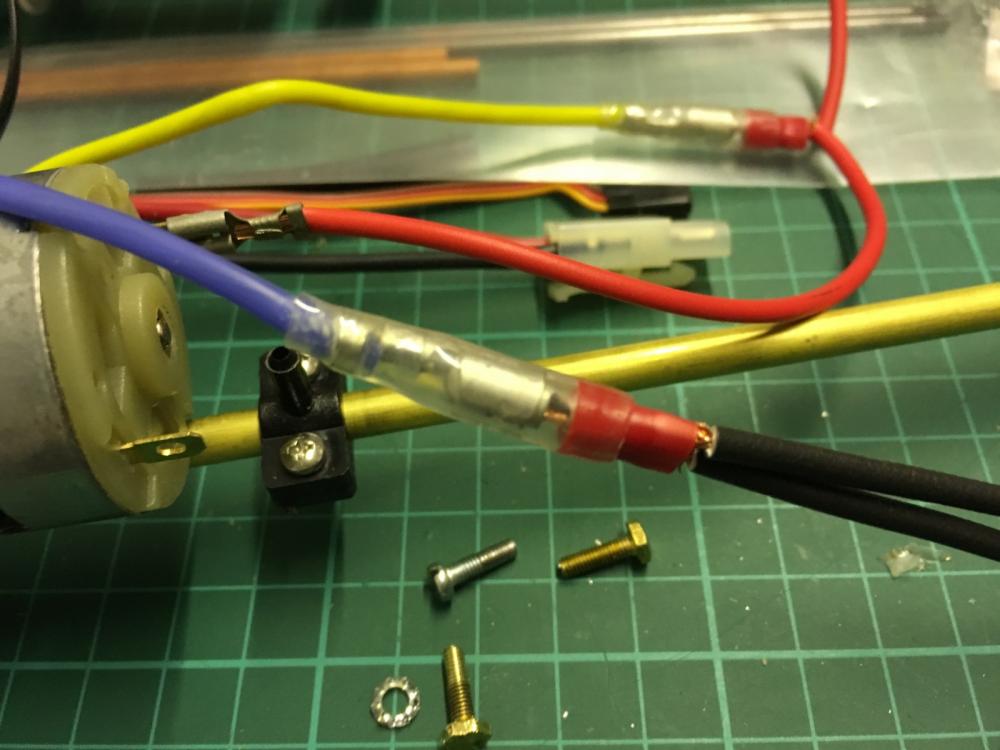
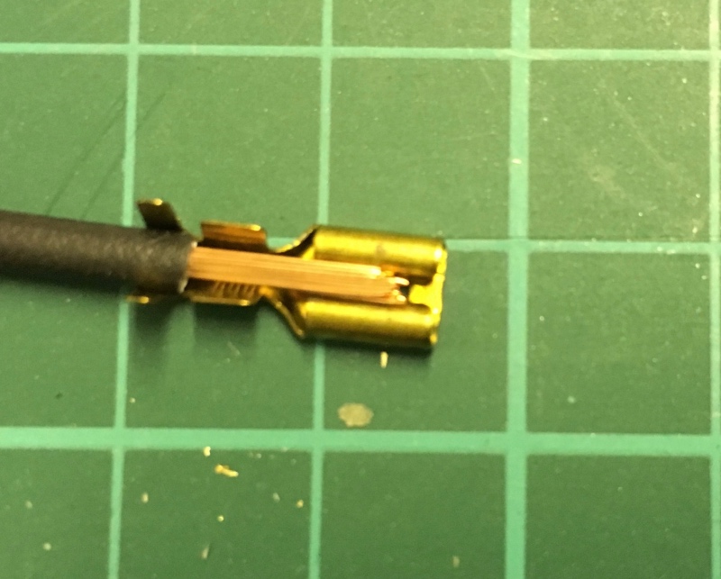
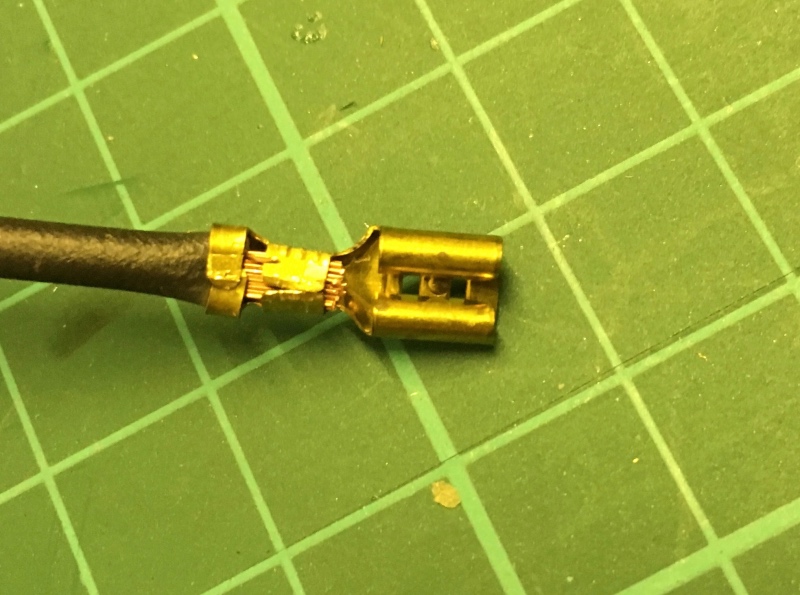
Some details on installing the wires: The instructions for the ESC (electronic speed control) show wiring for a single motor and it has indeed for 1 set of wires, so the wires should be extended for double wiring: I show here for the black wires, same to be done for the red wires as well. Then each wire will be connected to the opposite poles of the engines (e.g. if red goes to the [+] of the first engine, then it goes to [-] of the other engine vice versa). So, strip the both ends of the wires, with one end stripped longer than the other: I use this wire stripper for this purpose. It is a bit on the higher end, but still not too expensive, good to have at home: Keep around 1/3 of the strings and fold back the rest (to be trimmed later): Merge the 2 wires by twisting the strings you have kept: Trim the excess strings you have folded back: Insert the twisted strings to the male connector and squeeze firmly using a pair of plies so that they won't come out (alternatively and for better, you can solder): Insert the male connector to the female connector coming out of the ESC. Now the other end (the end which goes to the engines): Slide the strings into the connector. The stripped length was still too long I had to trim them a bit: Squeze firmly using pliers: The photo below shows both [+] and [-] wiring in place (Now a pair of careful eyes will notice that there are still wires exposed in the connection points which will cause harm if they get water. I won't do anything to them at the moment, but when I do the final installation, I will cover them with heat shrink tube):

- 414 replies
-
- 8
-
-
- riva aquarama
- amati
- (and 2 more)
-
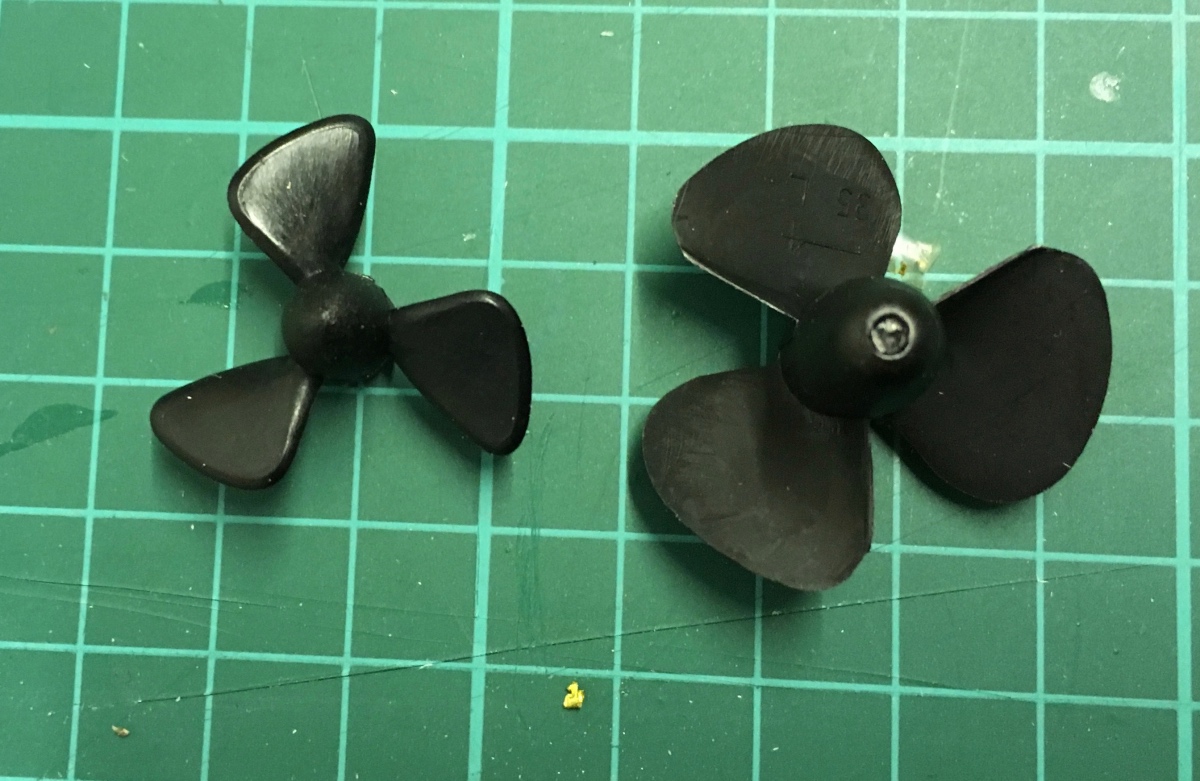
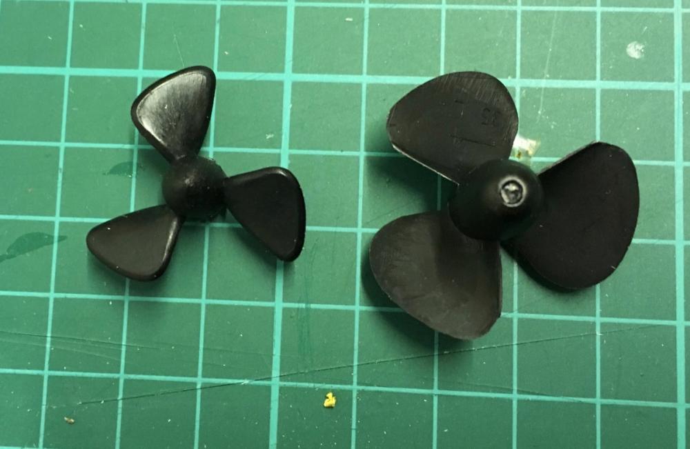
And the funny fact with propellers. On the left, the propellers which come with the standard kit. On the right, the propellers which come in the radio control extension kit. Now, what's this? Does it mean that if you build it as a display kit you should use smaller propellers? I already made up my mind with ordering nicer looking brass propellers but this kind of discrepancy should not be in a high class kit like this.
- 414 replies
-
- 6
-
-
- riva aquarama
- amati
- (and 2 more)
-
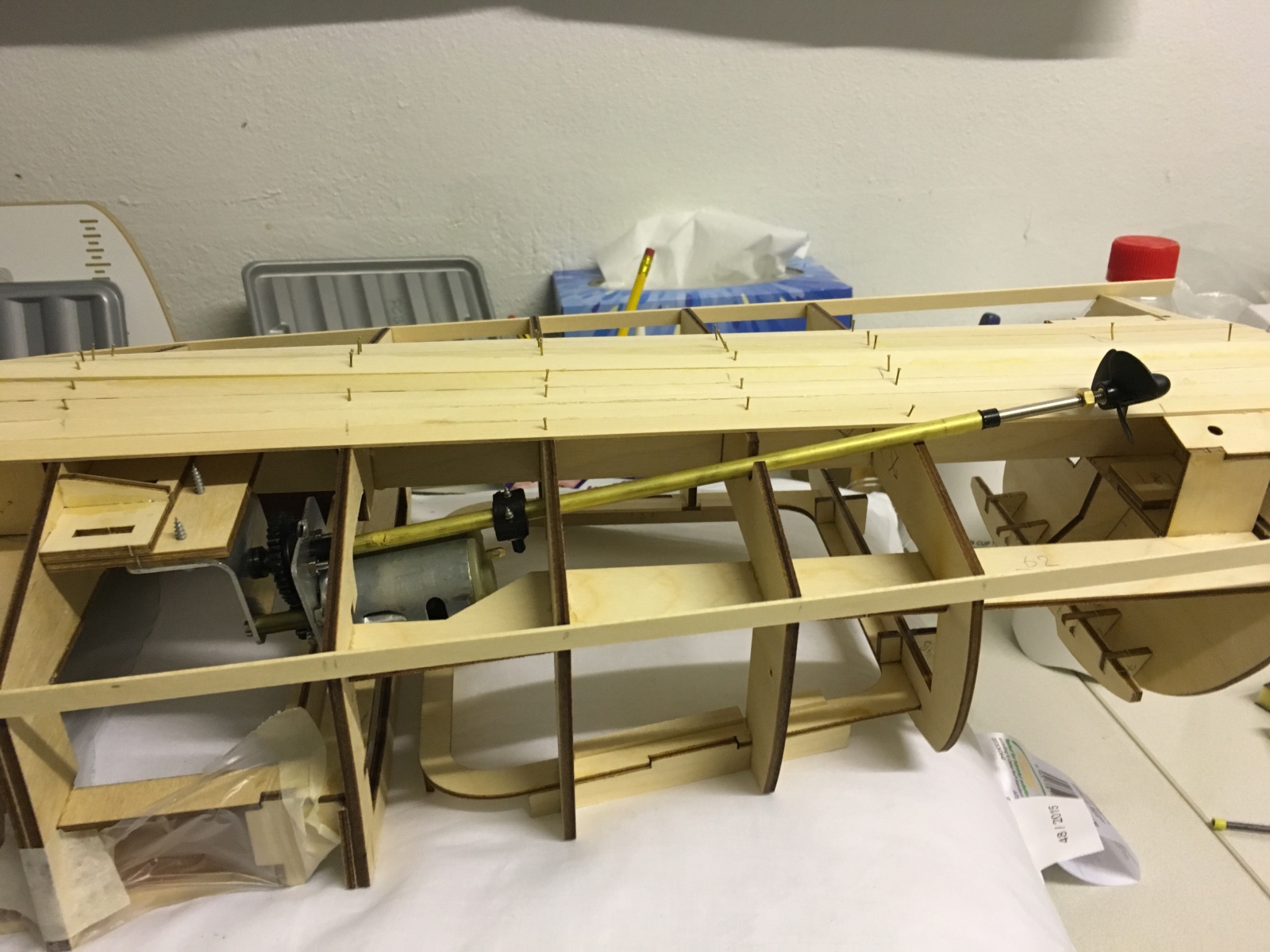
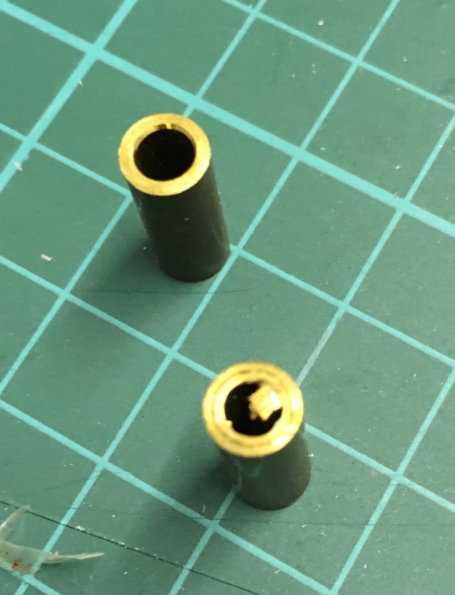
Now the bottom planking has reached the spot where the propellers and ruds will stick out, I resume assembly of the engine and rudder. I will fix them in their place so that the planking can continue. Assembling the rudders after the planks have been placed is not a big problem but since the propeller rod exits with an angle it would be extremely difficult to define the precise size, angle and the location of those hole after the planks have been glued. I can think of removing the engines once I've opened the hole. The spacers in the first engine set (which I had shown in my earlier posts) had unequal spacers (16mm vs 17mm) . Now the second set has equal size spaces (both 16mm). This means I will have to unassemble the first one and file the longer spacer by 1mm in order to equalize. This kit calls itself challenging but this is not what I would call a "challenge". It is fighting against poor quality. Remind you that the radio control kit is not made by Amati. However Amati sells it under their collection therefore they should be responsible for the contents. Having said that, I sent an email to Amati almost 2 weeks ago referencing this blog, asking how I can obtain a part which came broken in the package, but so far no response. Anyway, here are the spacers of the second kit. Correct in size, but one of them with burrs and impurities. Have to file it with a metal file.

- 414 replies
-
- 5
-
-
- riva aquarama
- amati
- (and 2 more)
-
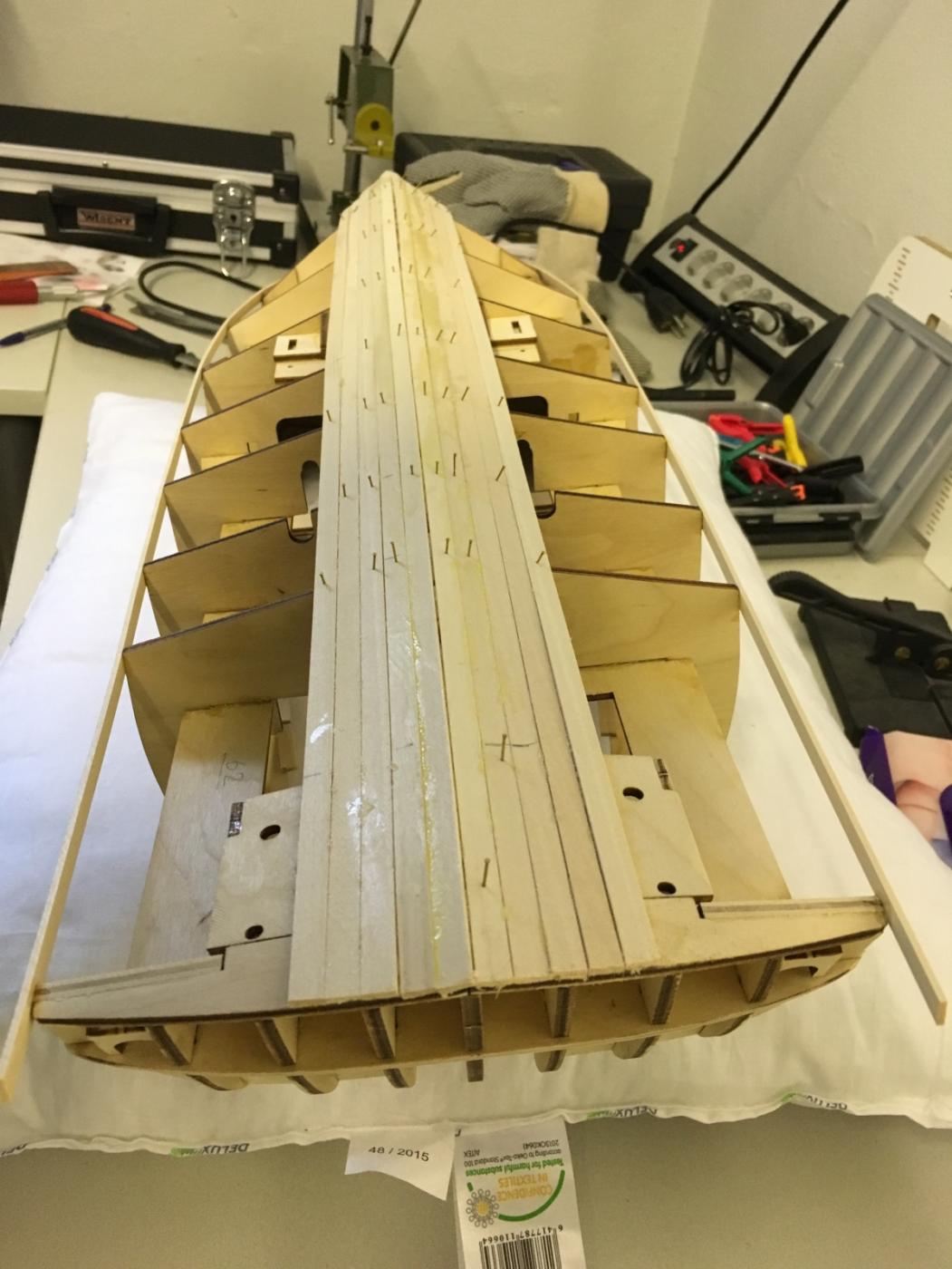
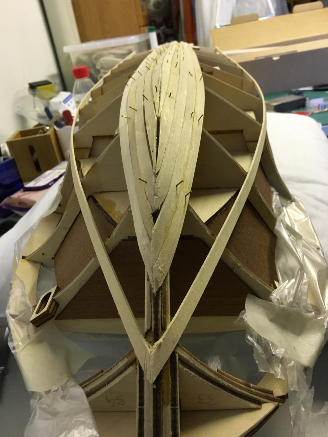
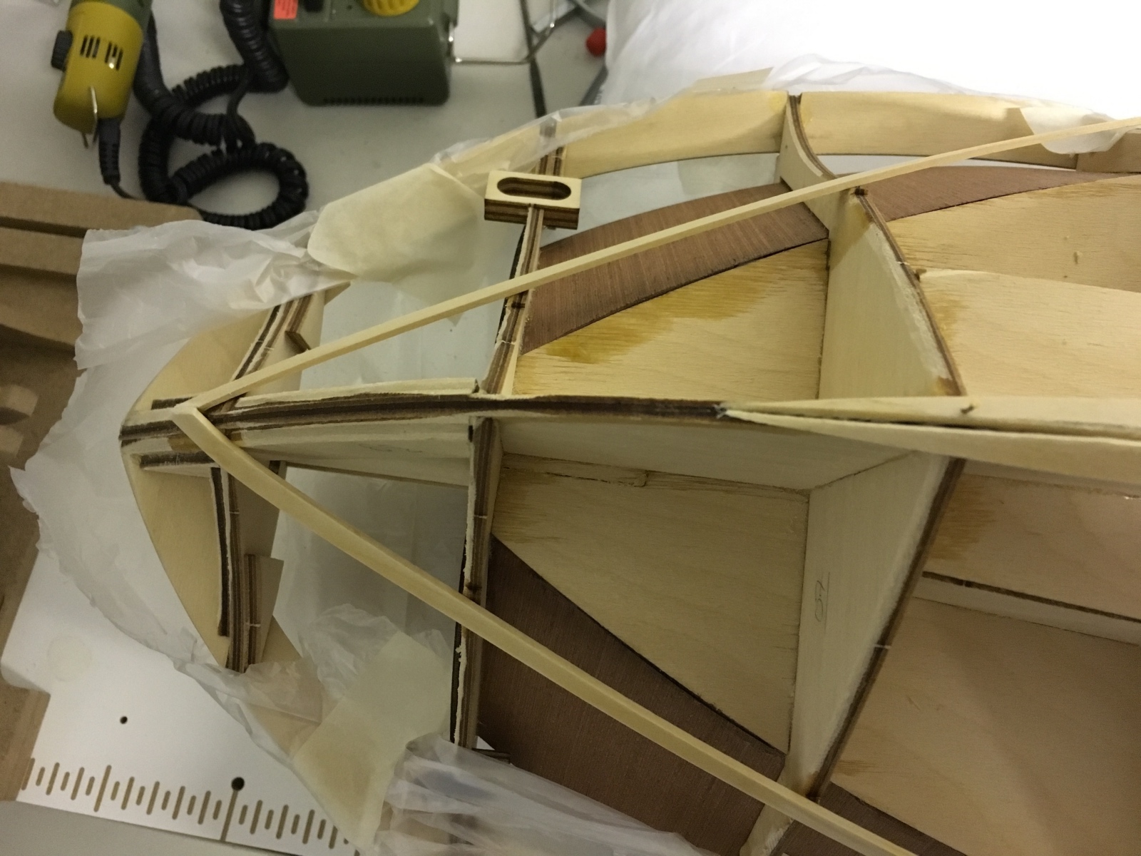
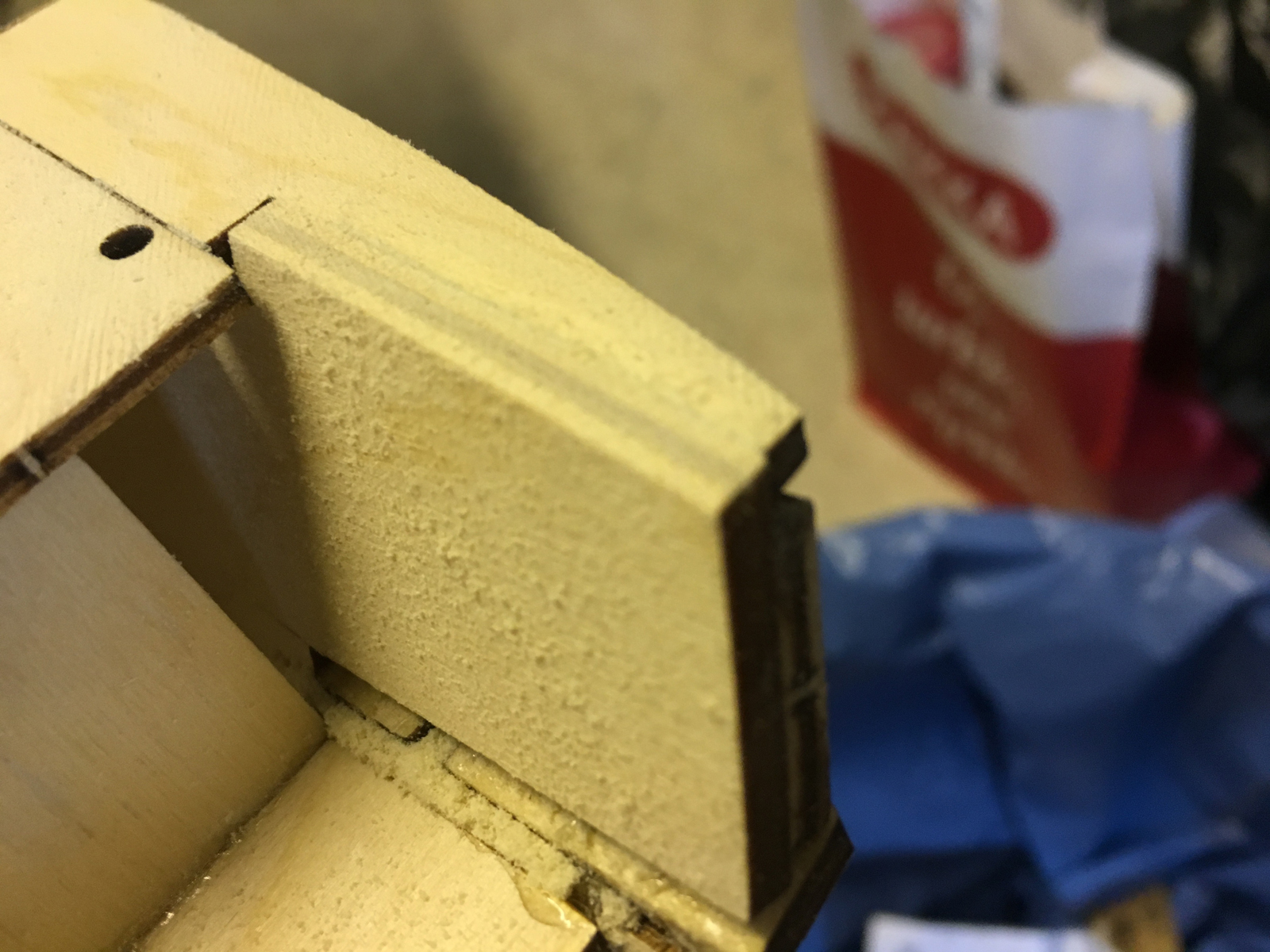
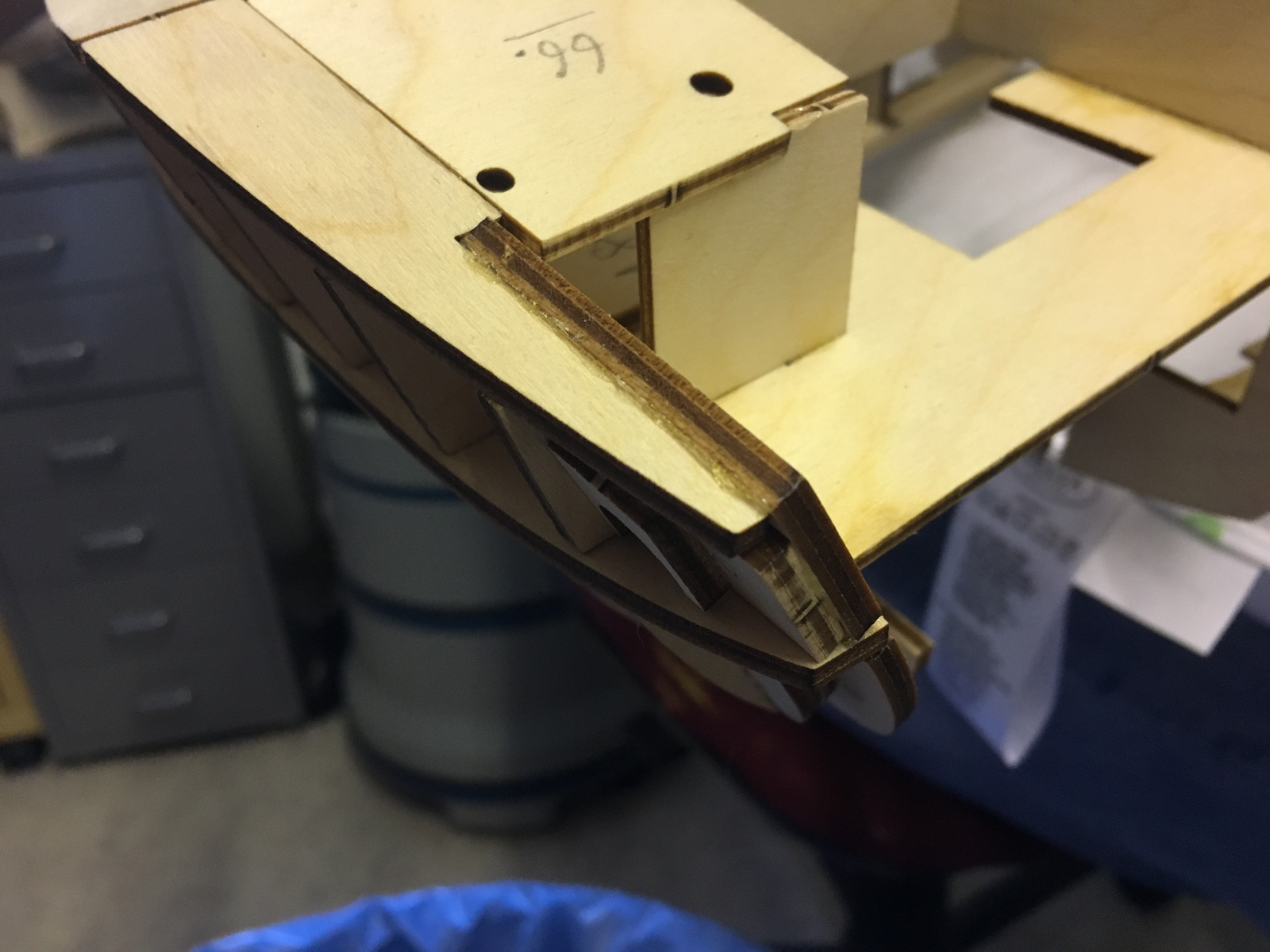
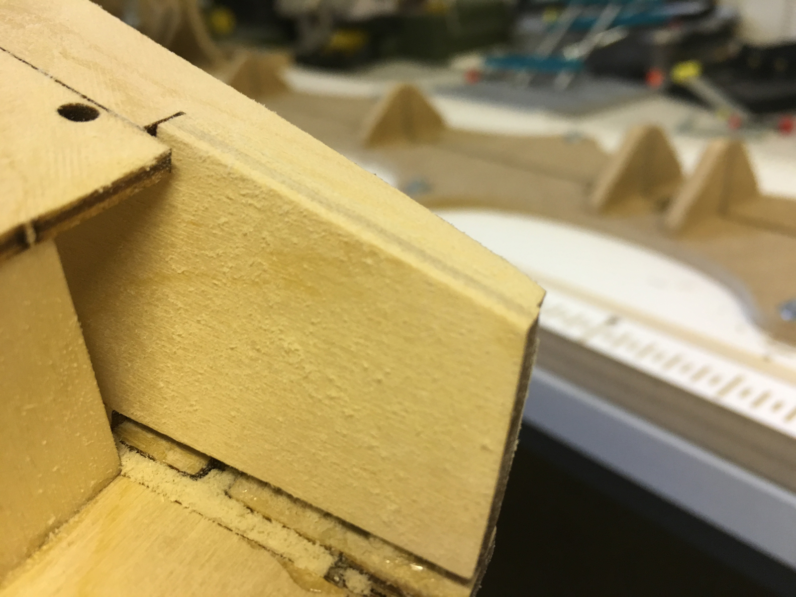
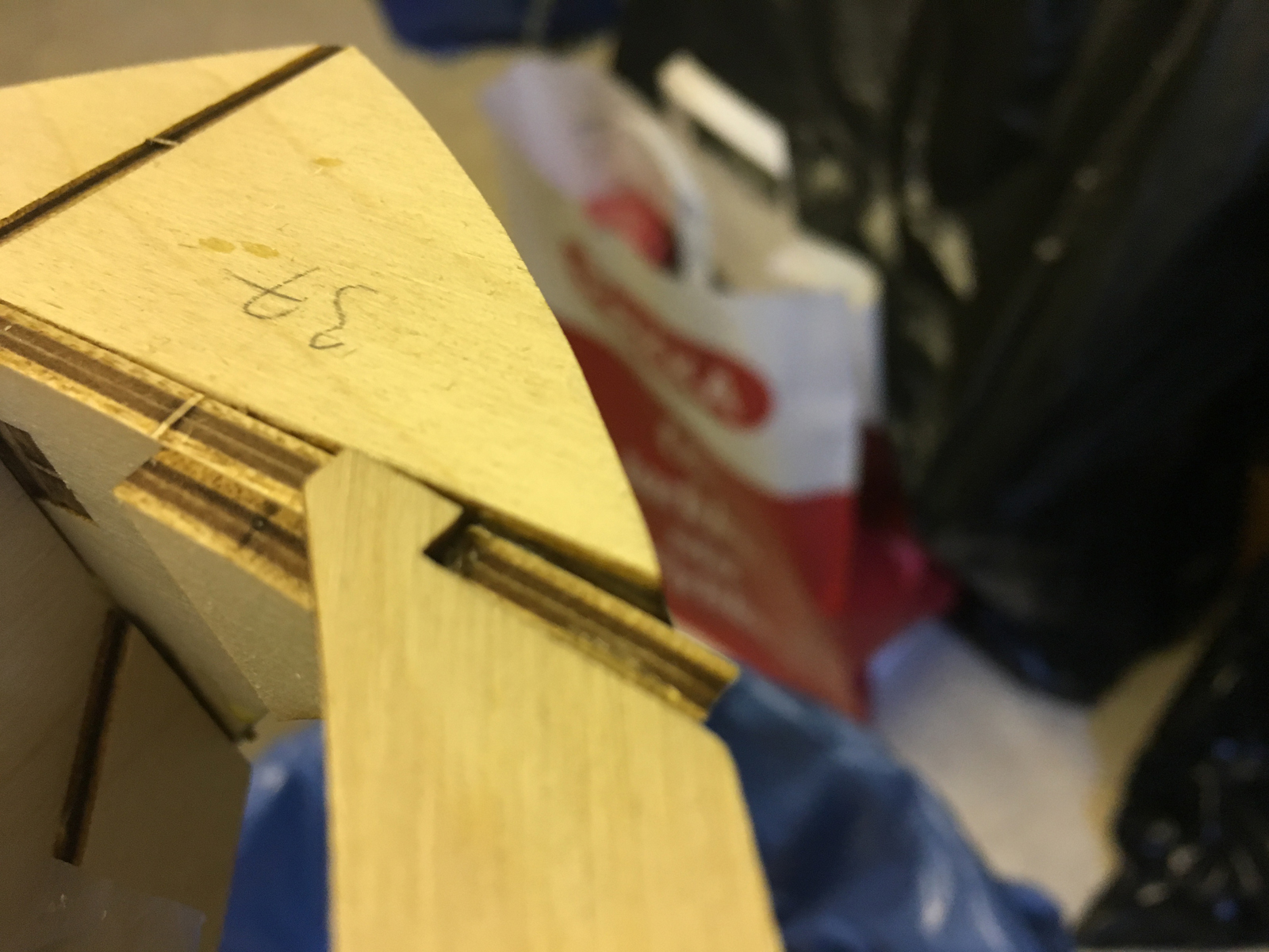
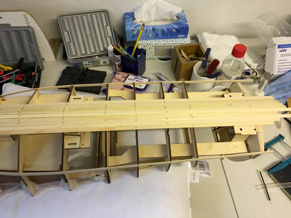
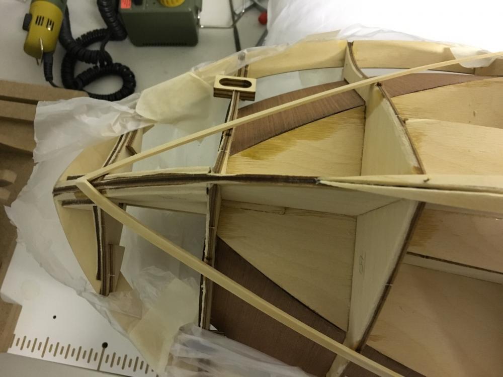
BUILD DAY 10. PLANKING CONT'D. Continuing with the planking today. I spent approximately 3 hours to glue 6 planks (3 each side). After that I have to stop for a while to install the engines in place in order to be able to mark the exit points of the rods correctly before planking the next strips. Same will go for the rudders as well. It will also make it harder to install the engines later as the planks will start to close the space available to install them easily. Aggressive curves begin to show:

- 414 replies
-
- 8
-
-
- riva aquarama
- amati
- (and 2 more)
-
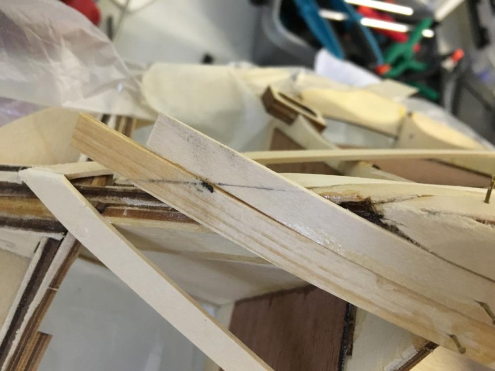
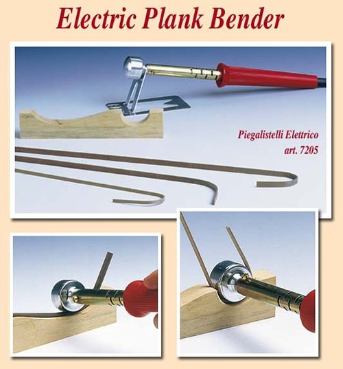
Hi Antony, Yes you have a point with shrinkage. I wait a little bit after bending it until the wood is somewhat dry, but it will sure still shrink further until it has been completely dried. I think this is the tool you've mentioned. I have it home and I have used it so far only for the most challenging bending jobs. Would be wise to use it also only for drying the wood before gluing.
- 414 replies
-
- 5
-
-
- riva aquarama
- amati
- (and 2 more)
-
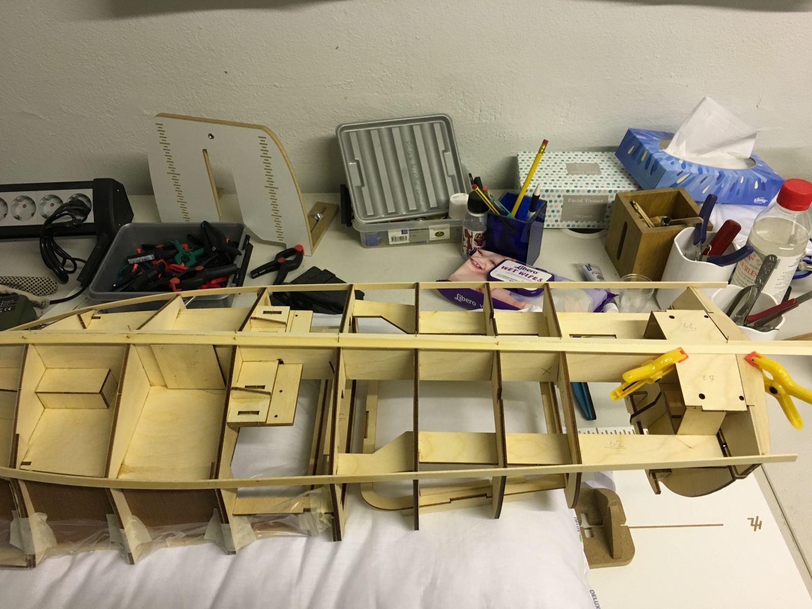
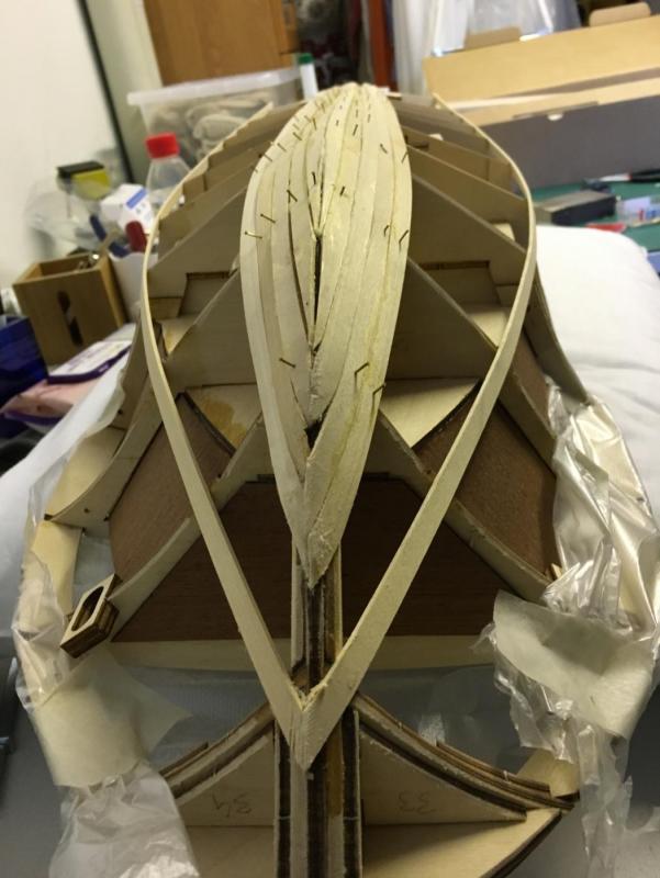
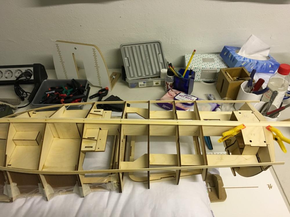
END OF BUILD DAY 9. 2:30 hours today. 31:00 hours into build in total. Two more planks before I call it a day. According to the instructions planking should continue from the bottom center after the first planks have been installed on the side at the designated spot. This is the status at the end of build day 9. Thanks for watching.
- 414 replies
-
- 8
-
-
- riva aquarama
- amati
- (and 2 more)
-
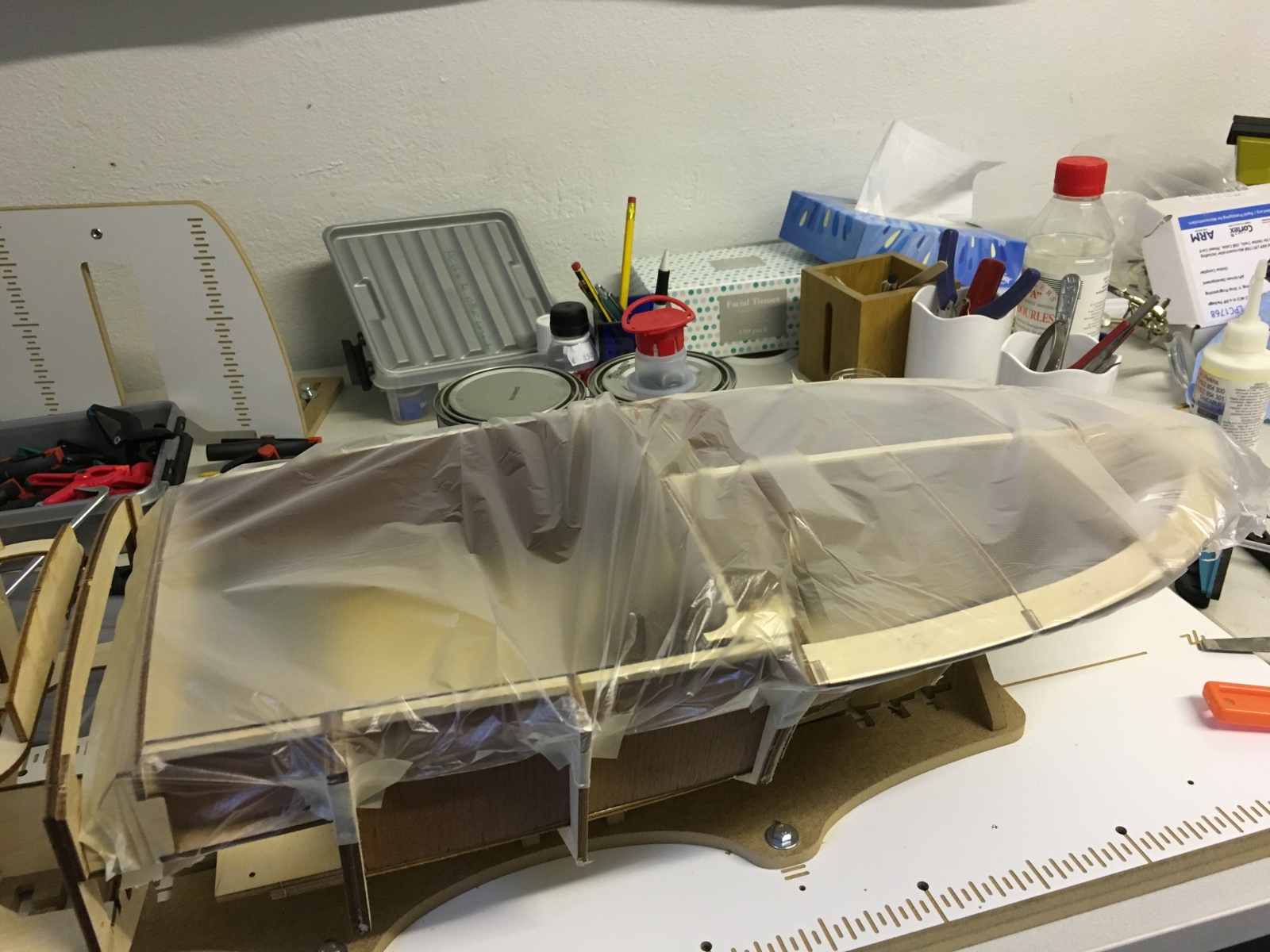
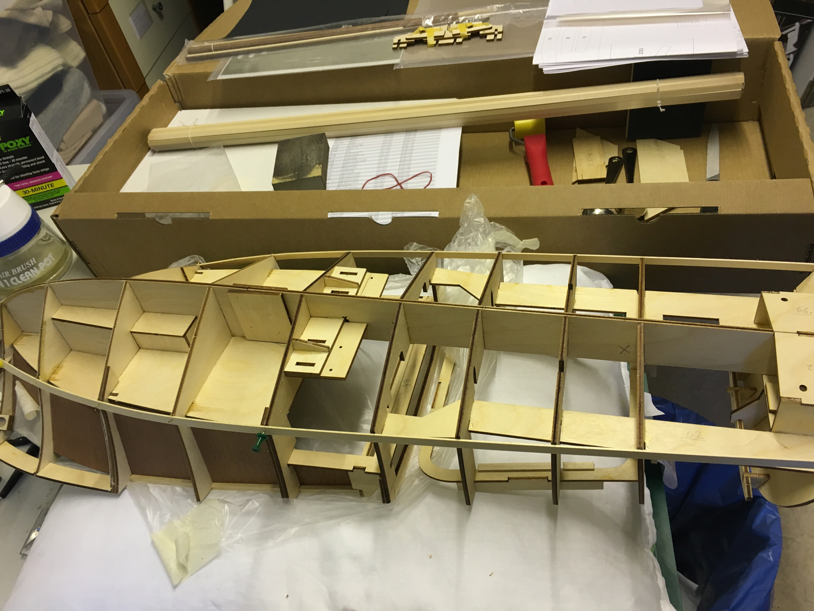
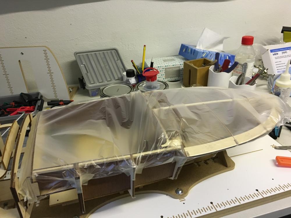
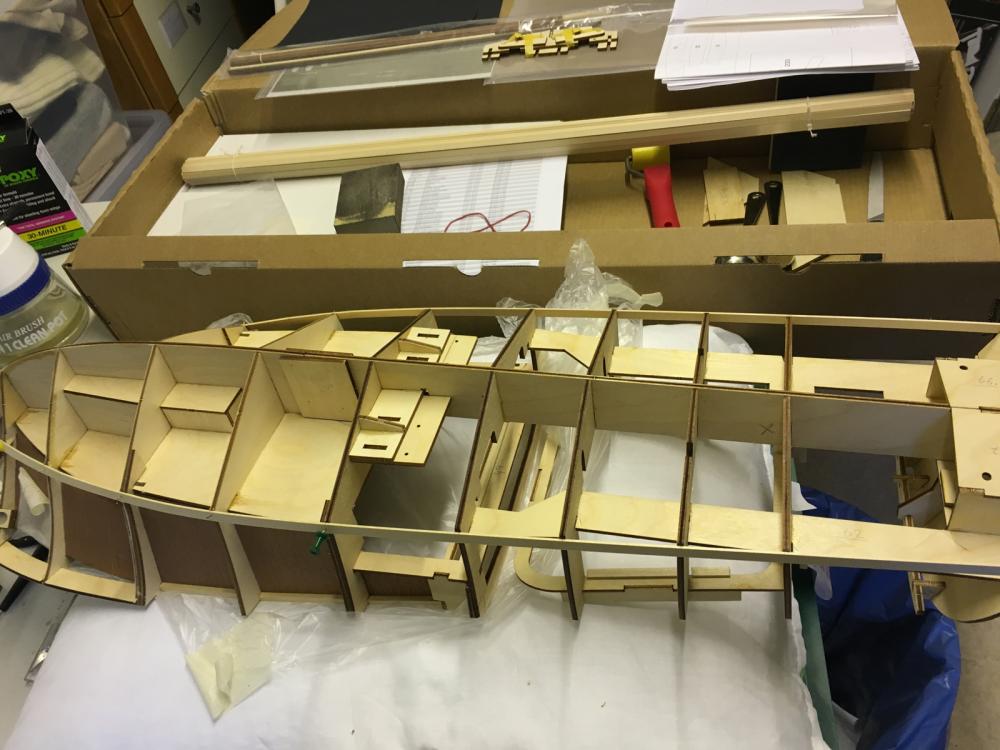
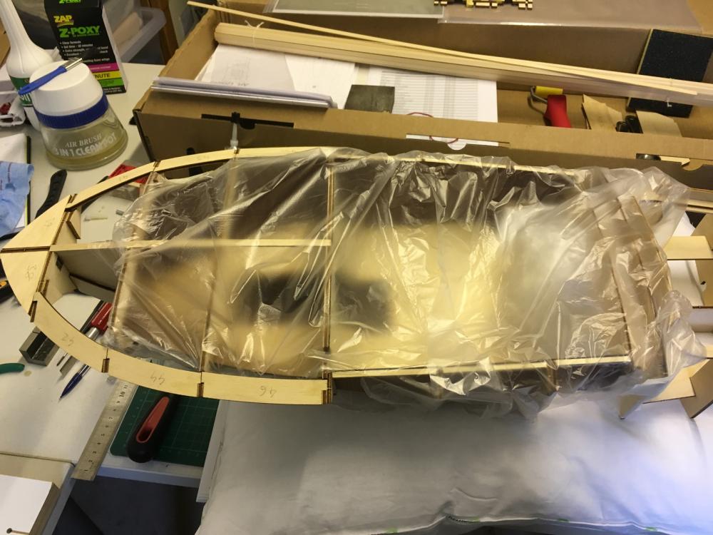
Now I cover the cockpit in order to protect it from dust and accidental damage.
- 414 replies
-
- 5
-
-
- riva aquarama
- amati
- (and 2 more)
-
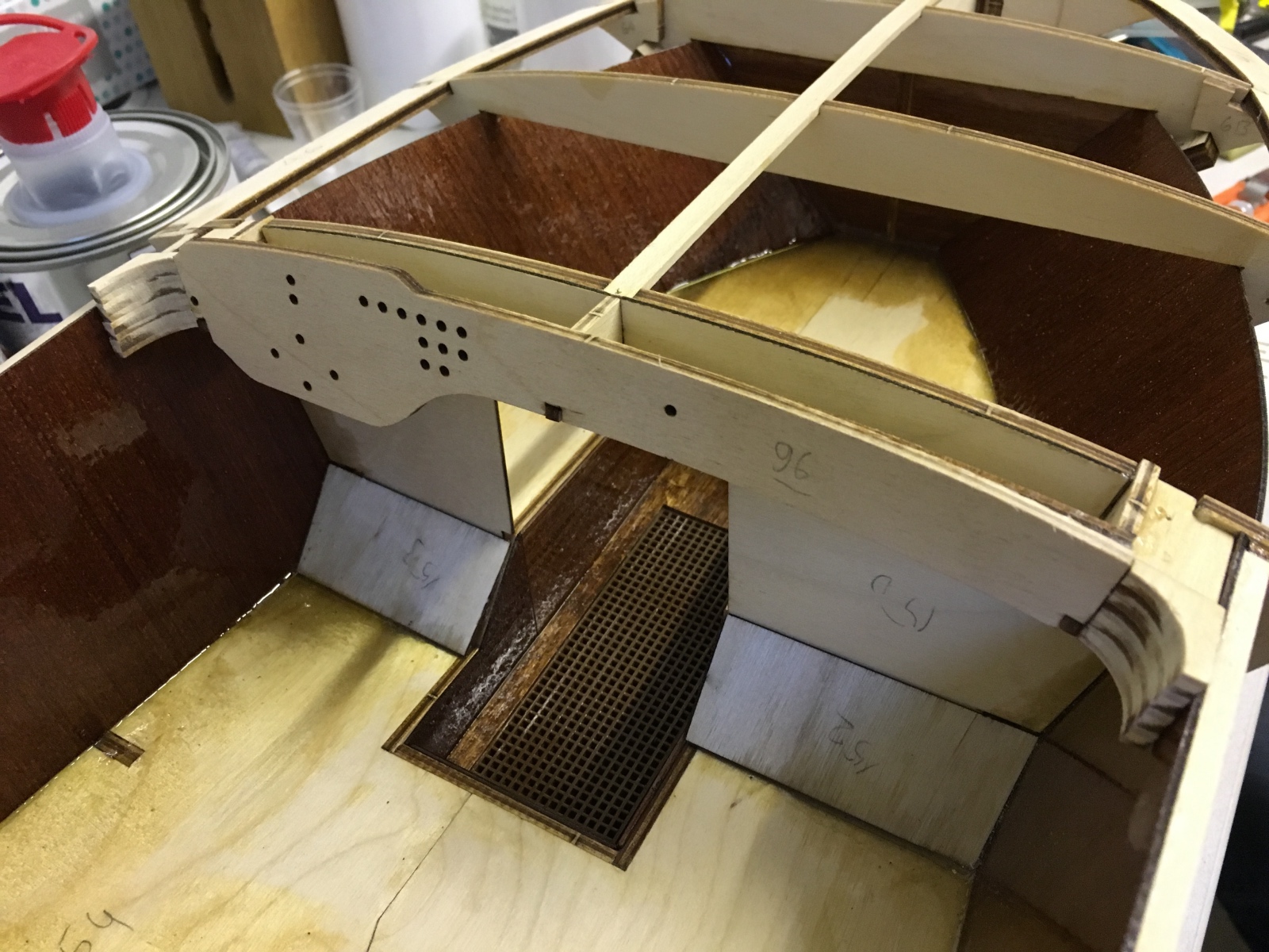
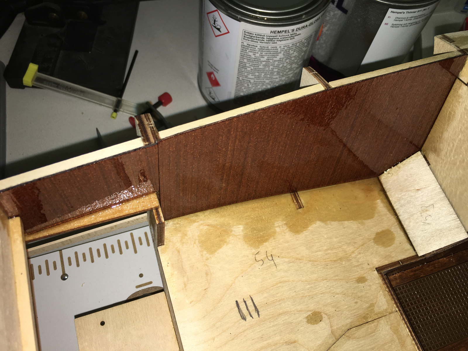
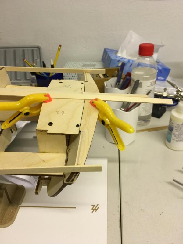
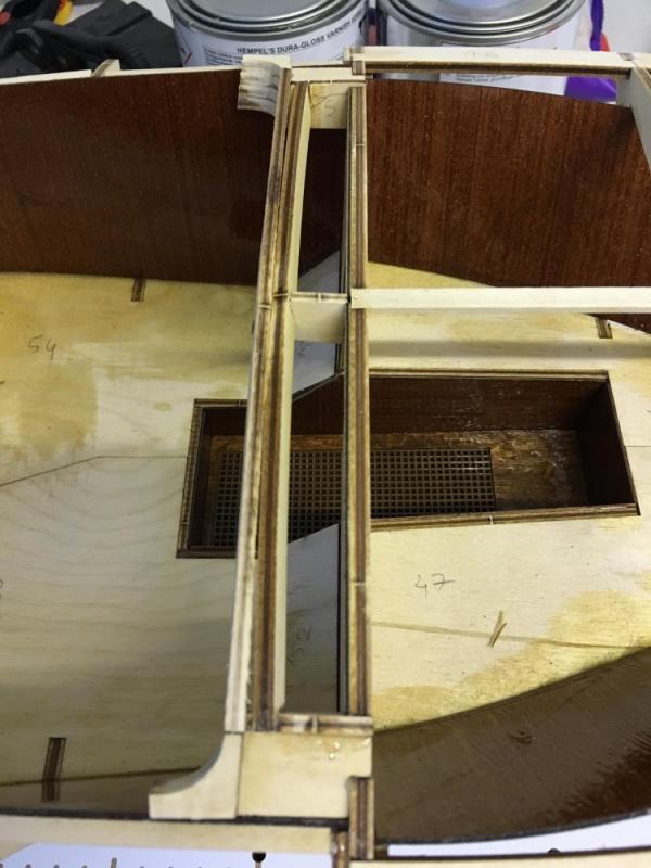
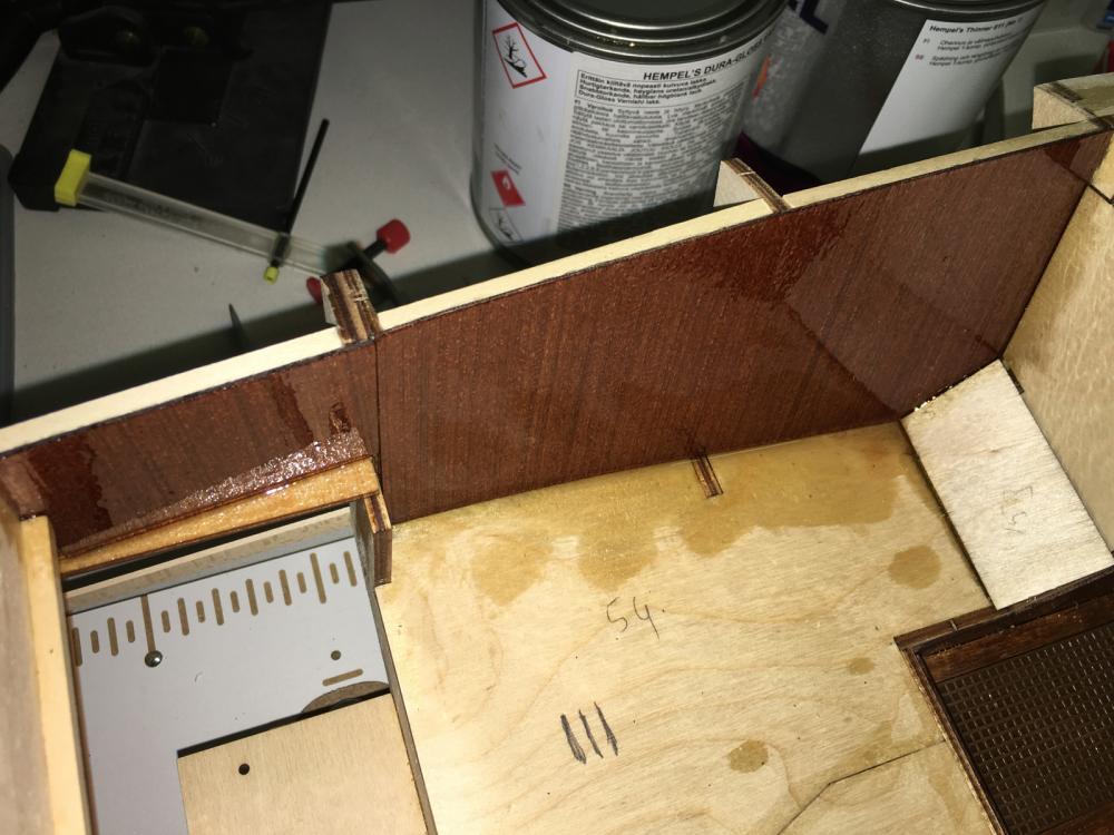
Dashboard in place. Note that the only contact point with dashboard and the support behind it is in the middle. It is because they lie on different vertical angle.

- 414 replies
-
- 6
-
-
- riva aquarama
- amati
- (and 2 more)
-
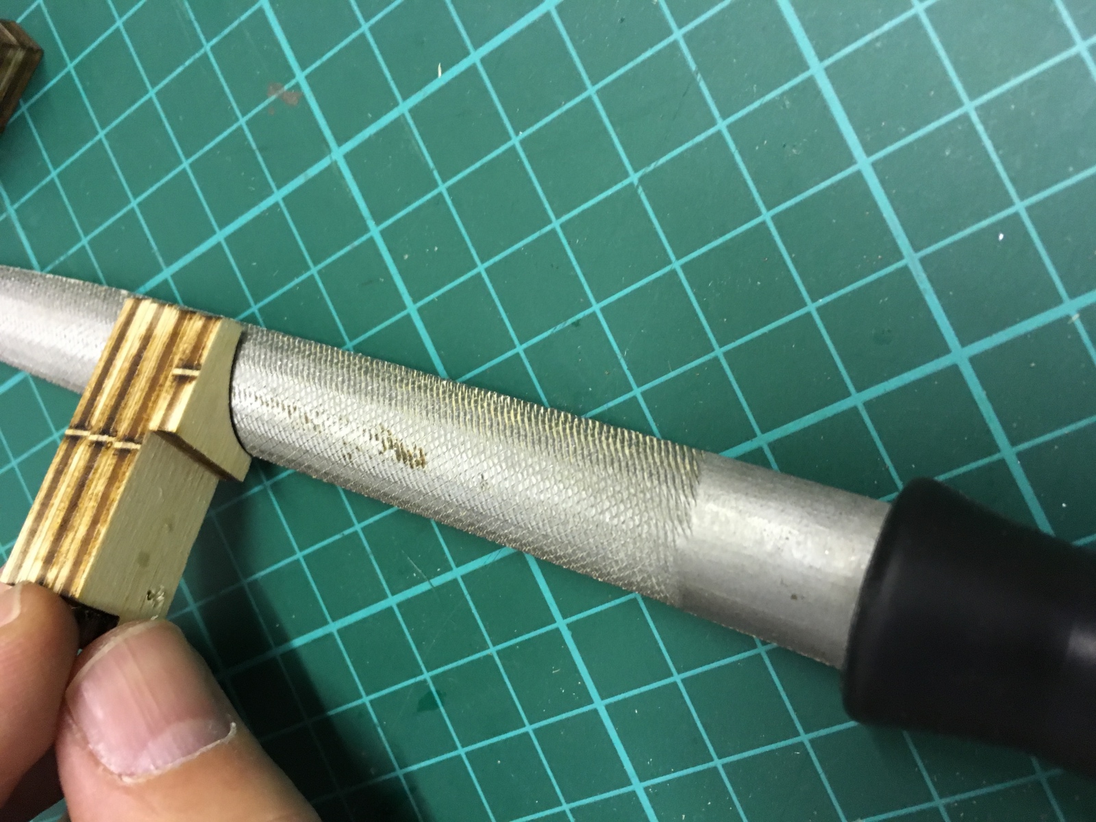
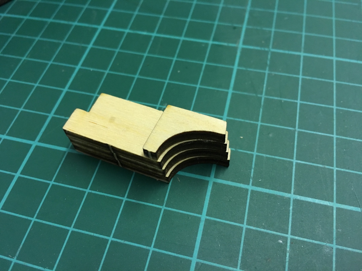
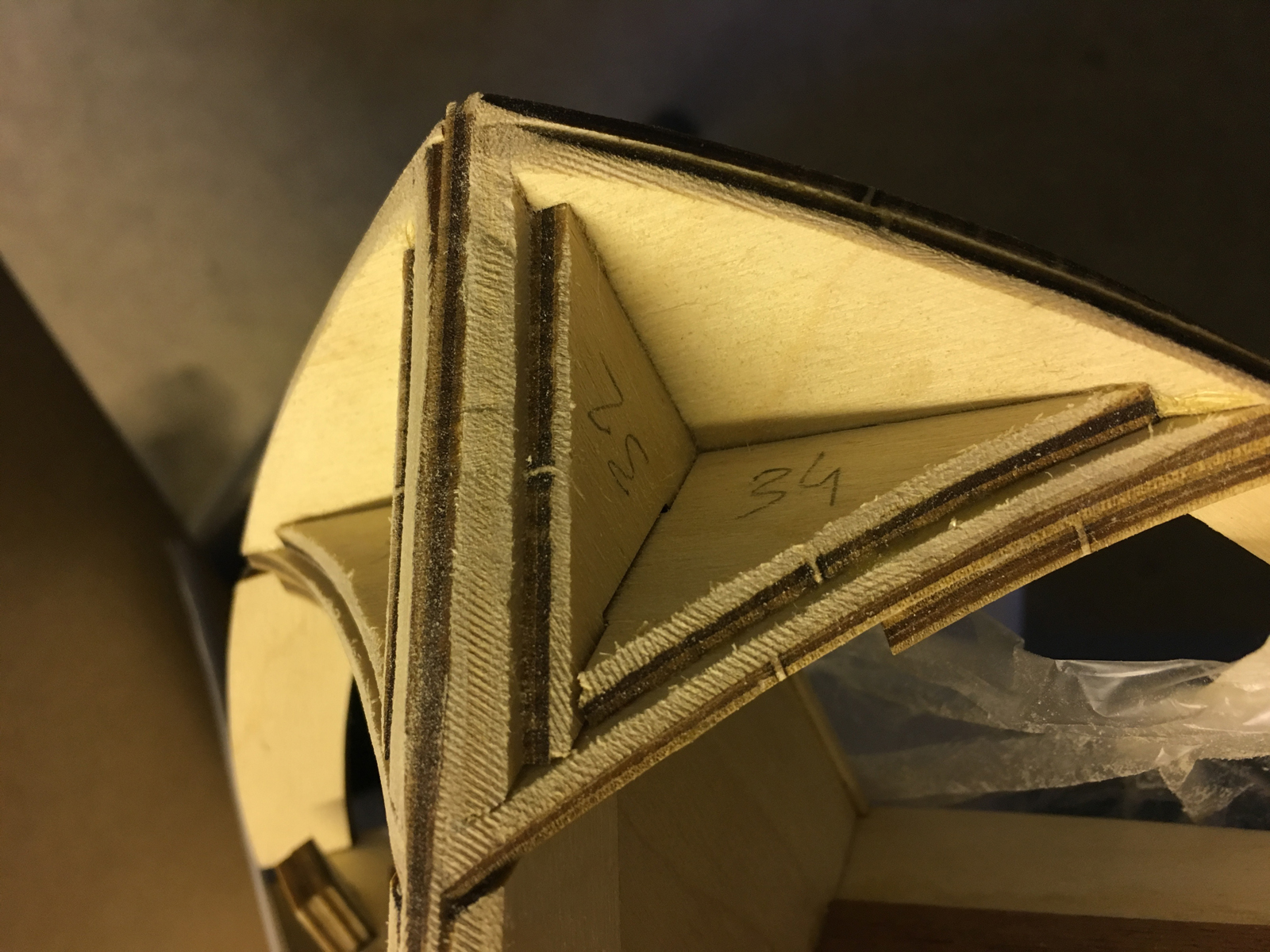
I was lucky that the file which I use had exact same size curve as the frames, making filing a breeze. If anyone would like to know, the file is a Bahco No.5. After filing:

- 414 replies
-
- 5
-
-
- riva aquarama
- amati
- (and 2 more)
-
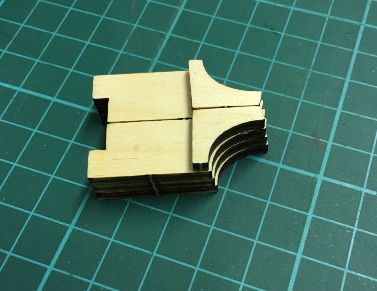
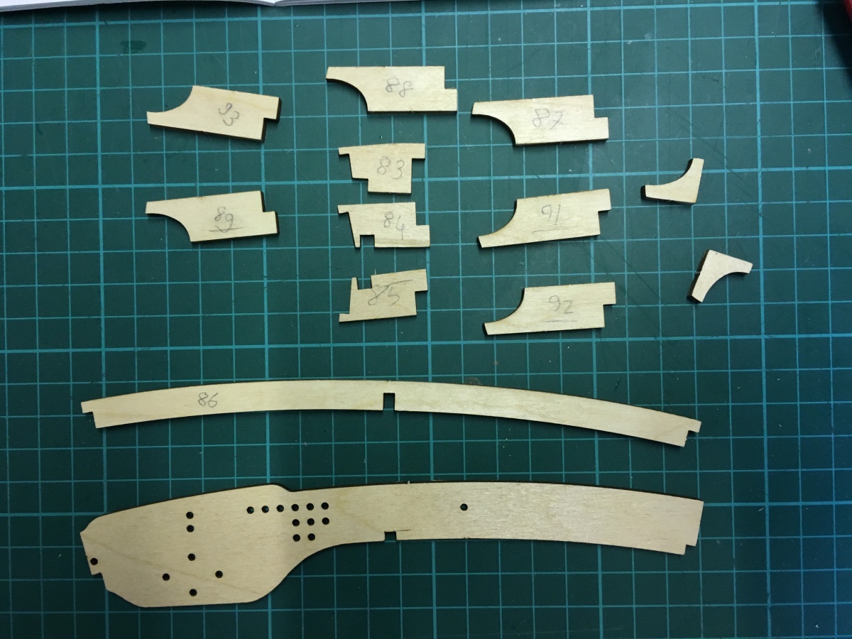
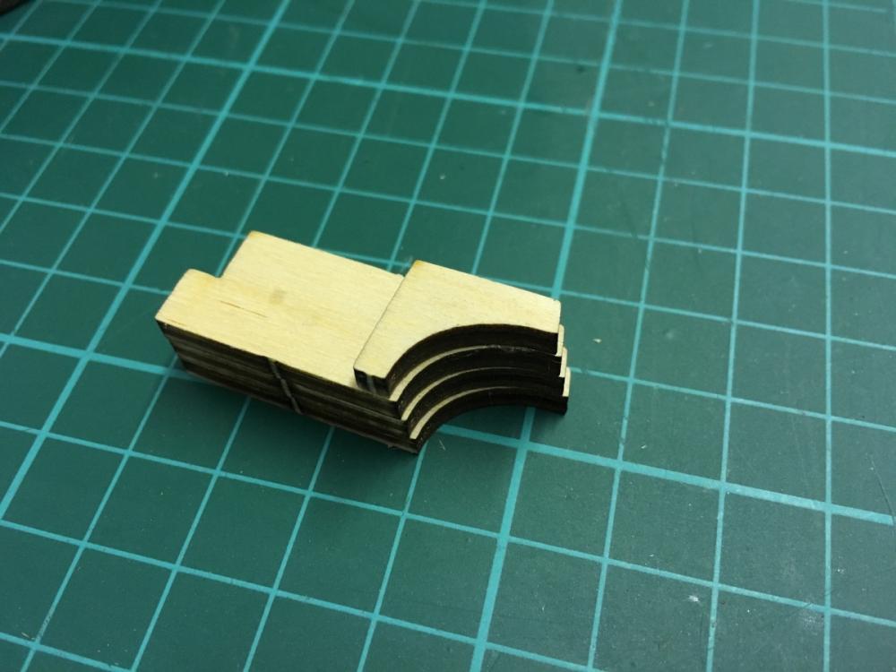
Ensuring that both pieces are symmetrical to each other:

- 414 replies
-
- 5
-
-
- riva aquarama
- amati
- (and 2 more)
-
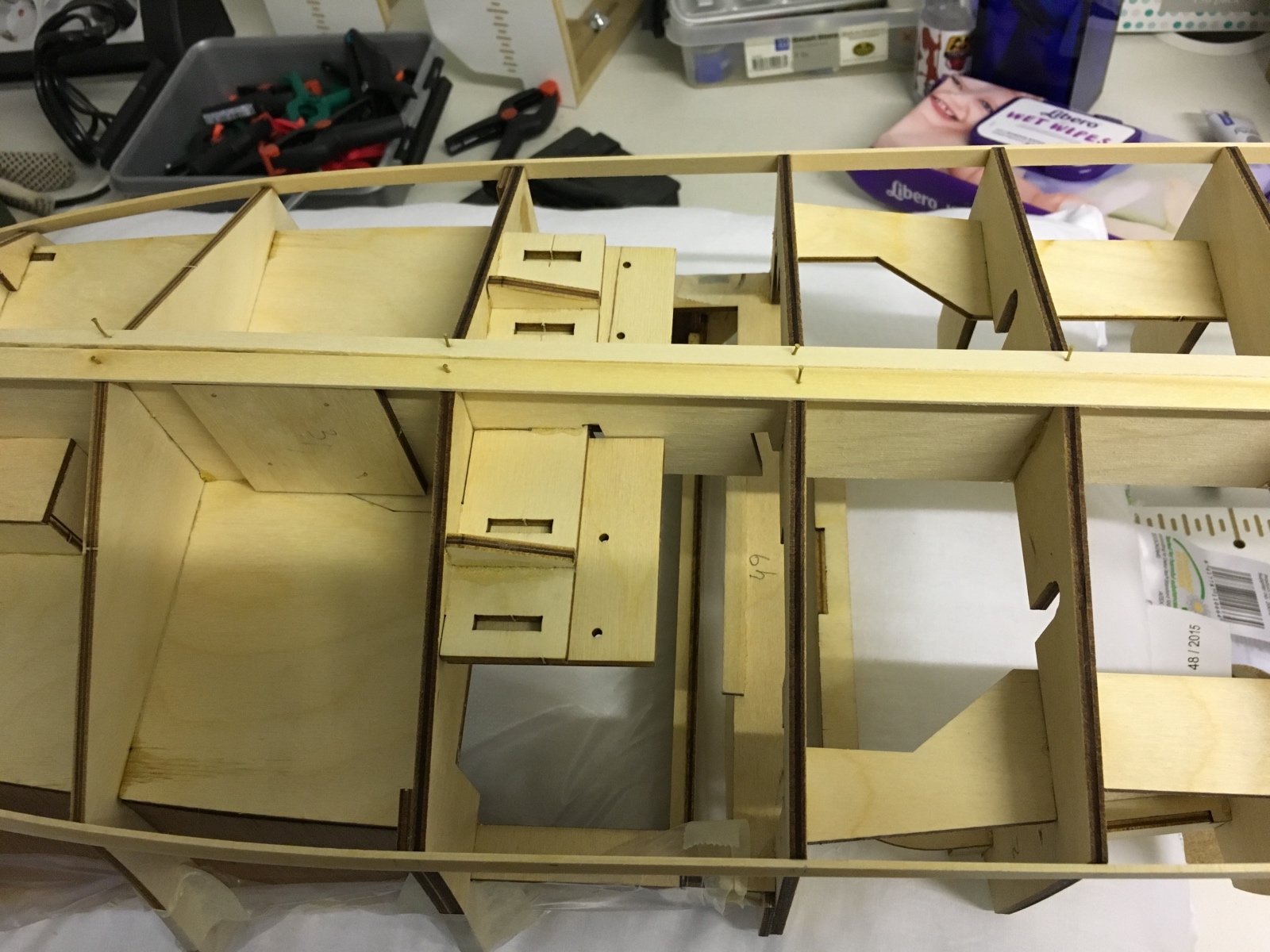
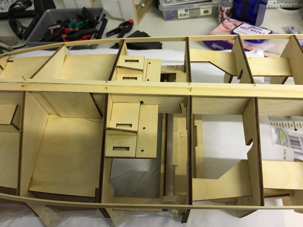
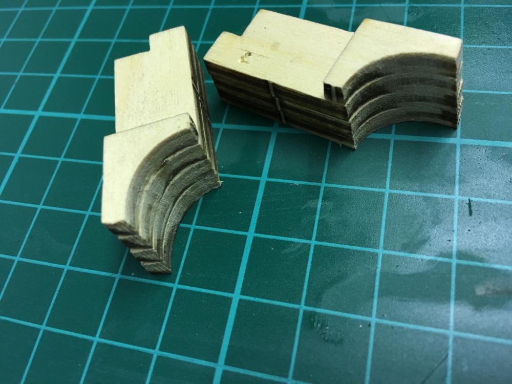
Frames on both sides of the dashboard. The pieces are glued as in the picture and then they'll be filed to smoothness once the glue has cured.
- 414 replies
-
- 4
-
-
- riva aquarama
- amati
- (and 2 more)
-
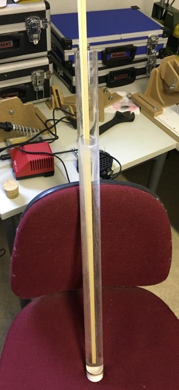
BUILD DAY 9. DASHBOARD Alright, I think that the cockpit has sufficient amount of varnish already and it is about time to install the final pieces: the dashboard. Planking may continue after that. But before that, I would like to show something I had made earlier for soaking the strips. This has been my best friend at making it easy to bend the strips with the help of Amati plank bender. It is basically a plexiglass tube cut to size, water tightened from the bottom . It also has a cork to close from the top (see on the left, on the table), but since Riva Aquarama's strips happen to be longer than the tube, the cork is not applicable. Having the strips rest in it a few hours, it is extremely comfortable to bend them.
- 414 replies
-
- 4
-
-
- riva aquarama
- amati
- (and 2 more)
-
That's a good advice, thanks. A simple accidental drop of varnish on the slip can indeed render the slip unusable especially if it hardens on the way of the moving parts.
- 414 replies
-
- 3
-
-
- riva aquarama
- amati
- (and 2 more)
-
END OF BUILD DAY 8. 2:30 hours today. 28:30 hours into build in total. One more layer of varnish before I stop. Looking shiny already. This is the status at the end of DAY8 .Thanks for watching.
- 414 replies
-
- 8
-
-
- riva aquarama
- amati
- (and 2 more)
-
2 hours of filing and finally I guess it is ready. I will honor the dusty work by placing the first planks on the hull:
- 414 replies
-
- 7
-
-
- riva aquarama
- amati
- (and 2 more)
-
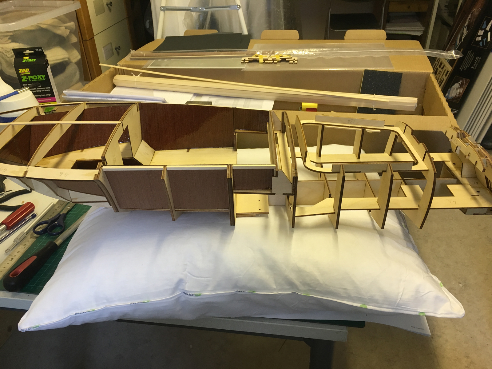
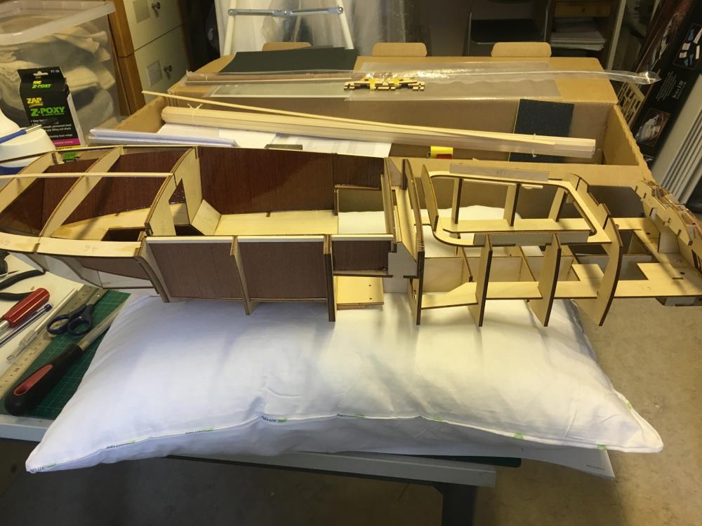
Placed the hull on the ultimate base for filing and planking: a pillow. My best choice so far to absorb the friction and pressure.
- 414 replies
-
- 7
-
-
- riva aquarama
- amati
- (and 2 more)
-
BUILD DAY 8. FIRST PLANKS Today is the time to start planking, finally... ... which means a lot of filing before putting the first plank. So first thing to do is to cover the (currently being varnished) cockpit against dust and accidental scratches:
- 414 replies
-
- 5
-
-
- riva aquarama
- amati
- (and 2 more)
-
You'll certainly need to move the white aligning tool along the keel in order to adjust each frame, however I at least did not necessarily have to screw it all the time. For me it was just enough to align the piece using the rules on both sides and hold it just there while gluing the frame to place. Screwing tightly to place would be probably needed if you want to use the aligning piece also as a support to the frame.
-
I think I will order Raboesch. Cormwallmodels shop seems to have a selection of them. They look good enough and the prices are affordable. I don't need anything heavy duty.
- 414 replies
-
- 6
-
-
- riva aquarama
- amati
- (and 2 more)
-
Hi Don, Yes you can move the white piece back and forward to align each of your frames. The screws which hold it are not permanently tight. They stay loose. You move it, and when it is in place, you tighten it.
-
END OF BUILD DAY 7. 5:30 hours today. 26 hours into build in total. One more layer of varnish before I stop. This is the status at the end of DAY7 .Thanks for watching.
- 414 replies
-
- 5
-
-
- riva aquarama
- amati
- (and 2 more)