HOLIDAY DONATION DRIVE - SUPPORT MSW - DO YOUR PART TO KEEP THIS GREAT FORUM GOING! (Only 24 donations so far out of 49,000 members - C'mon guys!)
×


aydingocer
-
Posts
916 -
Joined
-
Last visited
Content Type
Profiles
Forums
Gallery
Events
Everything posted by aydingocer
-
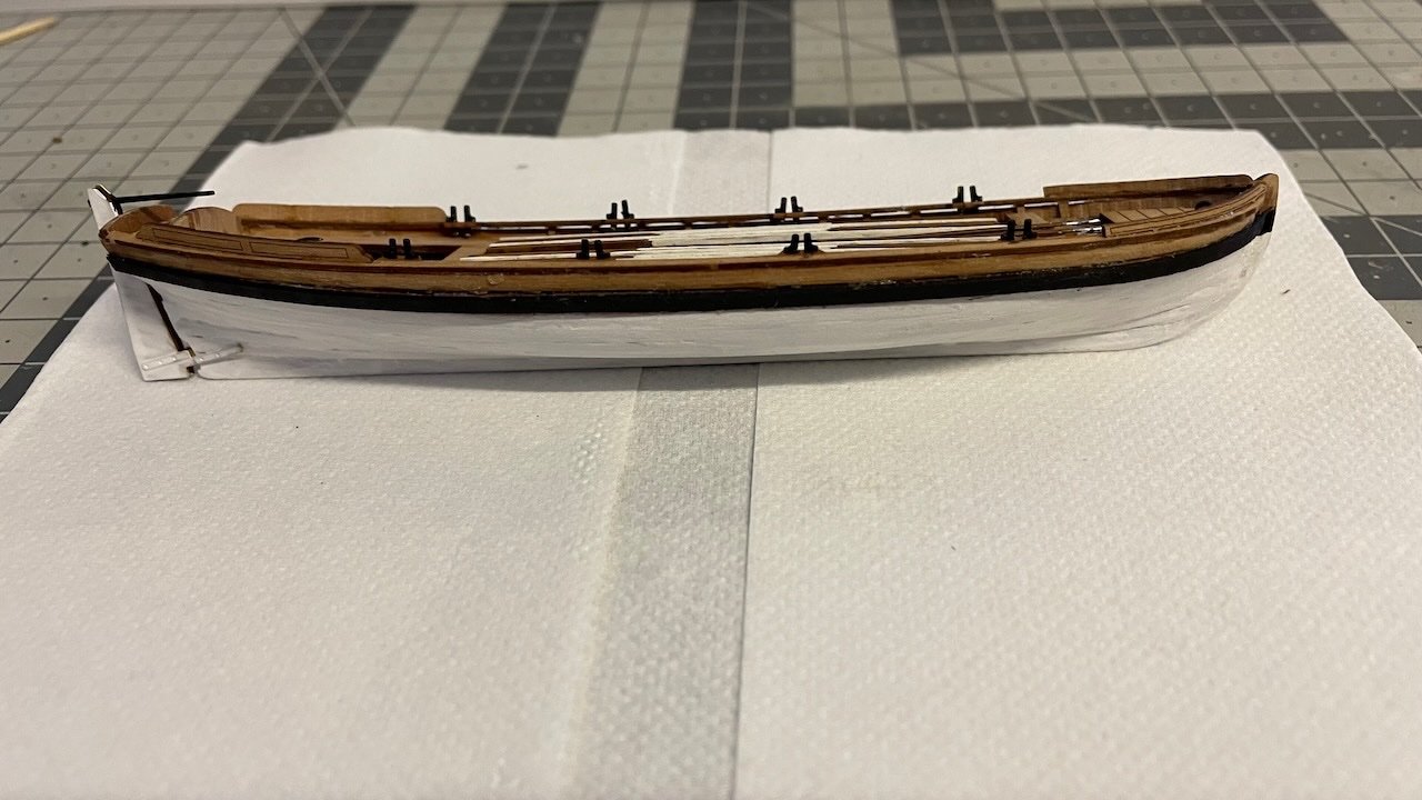
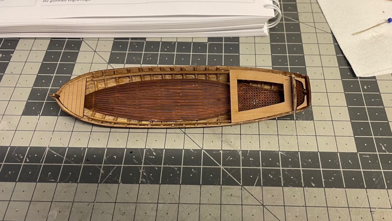
 Photos 635-636: Here the 28 foot pinnace ready. Overall I am happy with the result. This is one down and I hope I can apply my learnings to building the remaining two boats. The boats will stay aside for a while in order not to obstruct rigging. That's all for today. Thanks for watching!
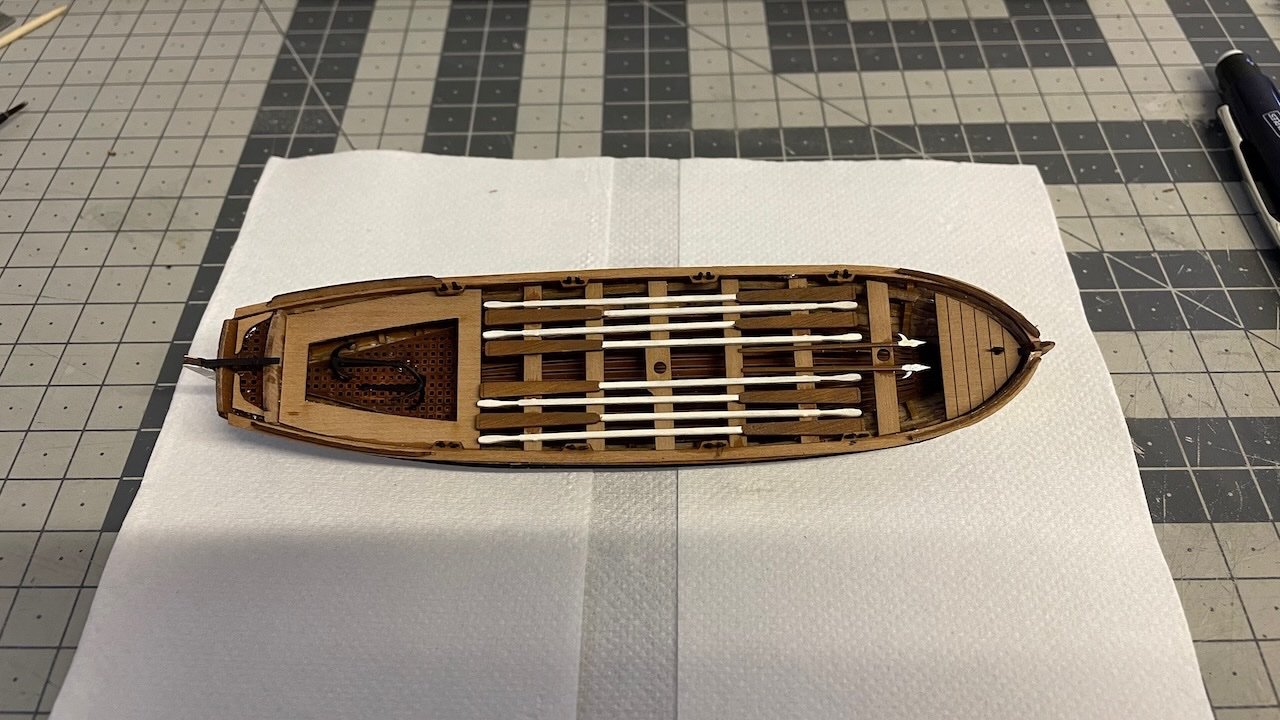
- 426 replies
-
- 11
-

-

-
- Vanguard Models
- Sphinx
- (and 1 more)
-
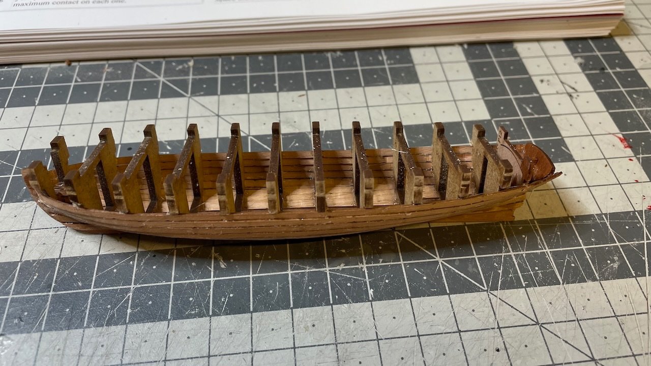
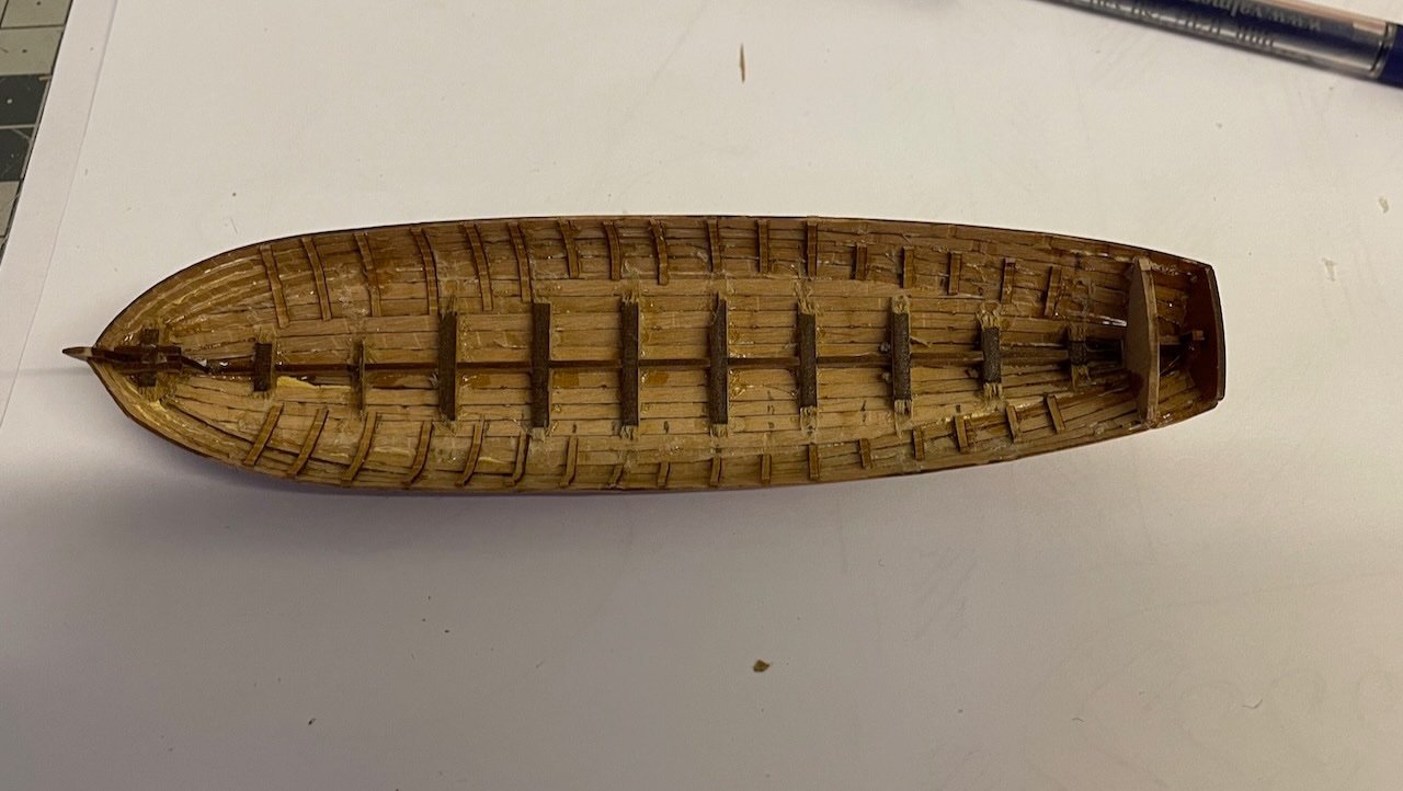
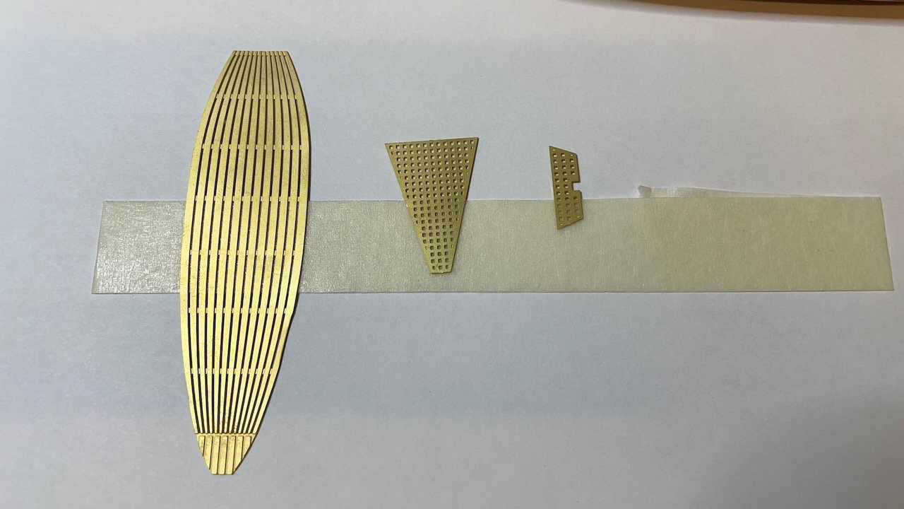
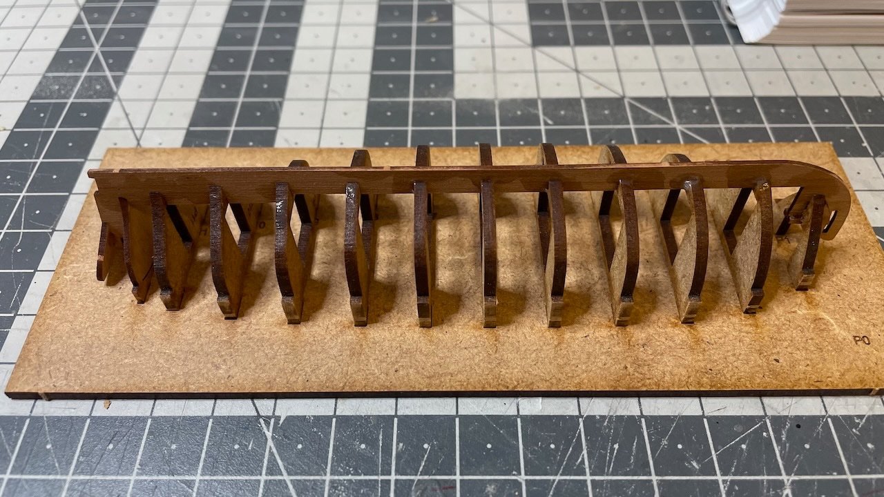
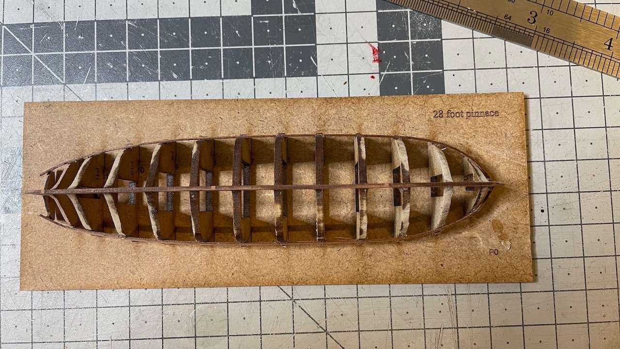
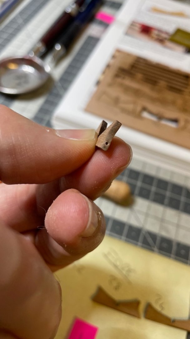
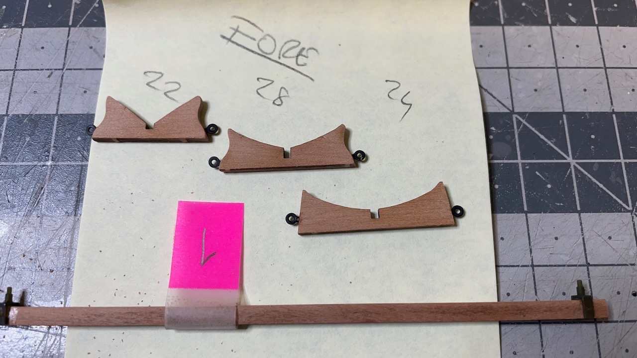
Photos 626-628: Time to remove from the base and rip the bulkheads. Photos 629-630: Installed the ribs abd the other components seen in the photos. There are some optional paint job steps in the manual, to give a more realistic wooden look to the etched parts, which I skipped. Here I used a brown paint I had in my stock.
- 426 replies
-
- 5
-
-
- Vanguard Models
- Sphinx
- (and 1 more)
-
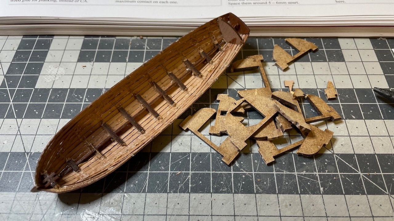
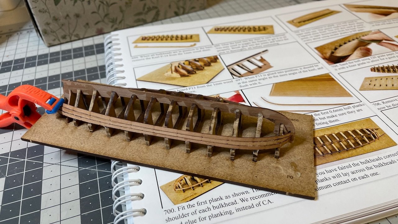
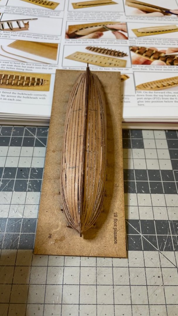
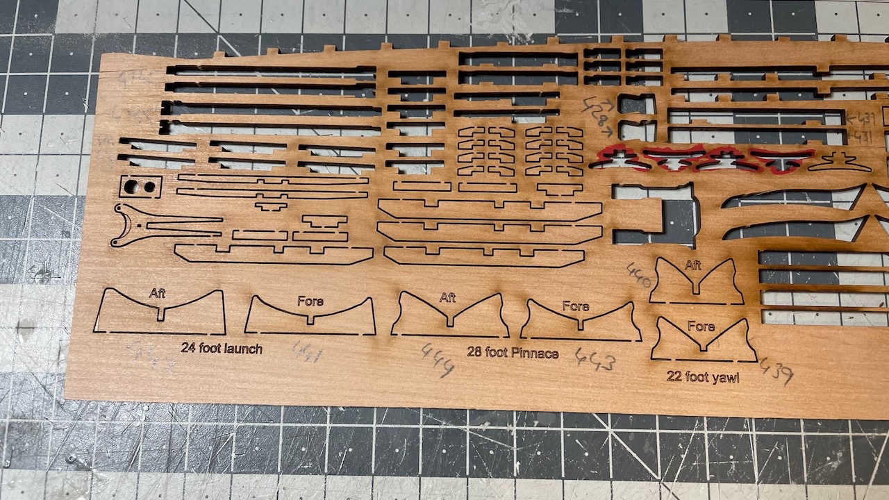
Build Days 72-75: 14 hours / Total 178 hours It has been a while since my post. Last time I posted I was about to start ship's boats. I wanted to make sure I finished a boat before I share the build process. I started with the 28 foot pinnace. It took 14 hours to get it ready. Photo 621: I used the same method of brushing diluted wood glue for fixing the bulkheads to the keel. Photos 622-624: Left it overnight to let the glue to dry. Then fairing the bulkheads and planking commences. Photo 625: Planking went overall well. I think after the 4th row of planking from the top, I coninued from bottom (i.e. keel) up. At this stage I am relying on sanding and filling the gaps in order to get a smooth surface, which will be painted.

- 426 replies
-
- 5
-
-
- Vanguard Models
- Sphinx
- (and 1 more)
-
Thanks for the advice James. I will certainly take my time with building these boats.
- 426 replies
-
- 2
-
-
- Vanguard Models
- Sphinx
- (and 1 more)
-
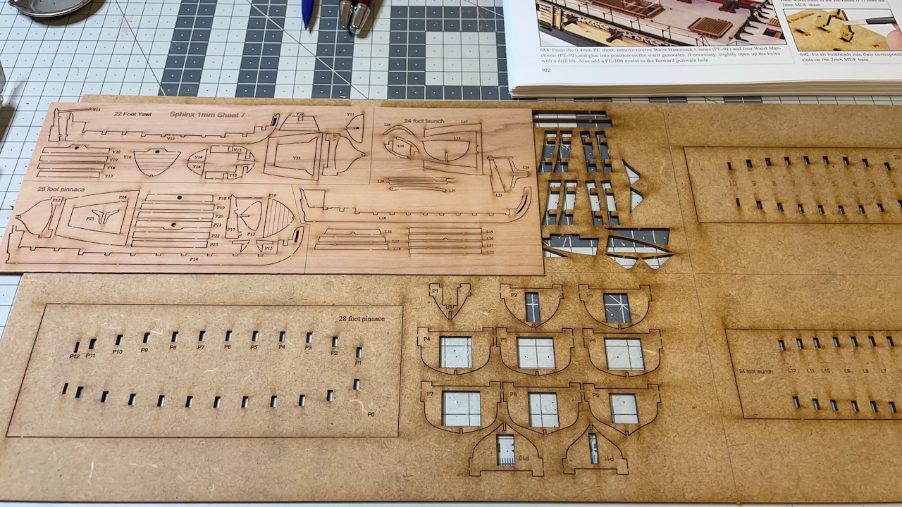
Photo 620: Coming up Next! Ship's boats. This is the most intimidating part of the build for me. I had tried to build the life boat once and failed in one of my earlier models. Ever since I always chose the easier option and went with the ready plastic hulls. This time I want to give them a try. Let's see how well I will achieve. That's all for today. Thanks for watching!
- 426 replies
-
- 6
-
-
- Vanguard Models
- Sphinx
- (and 1 more)
-
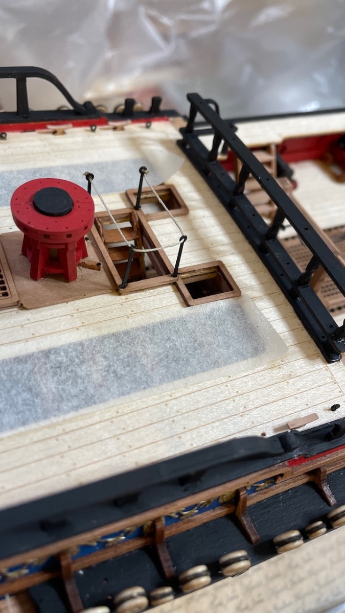
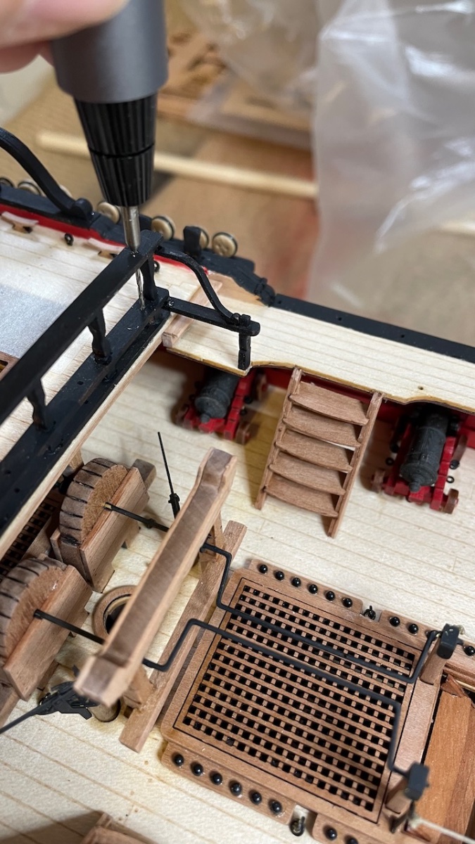
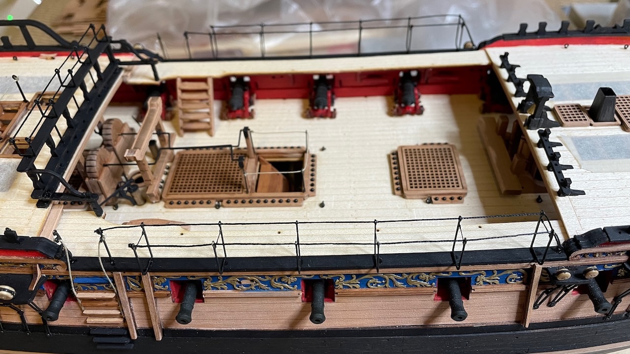
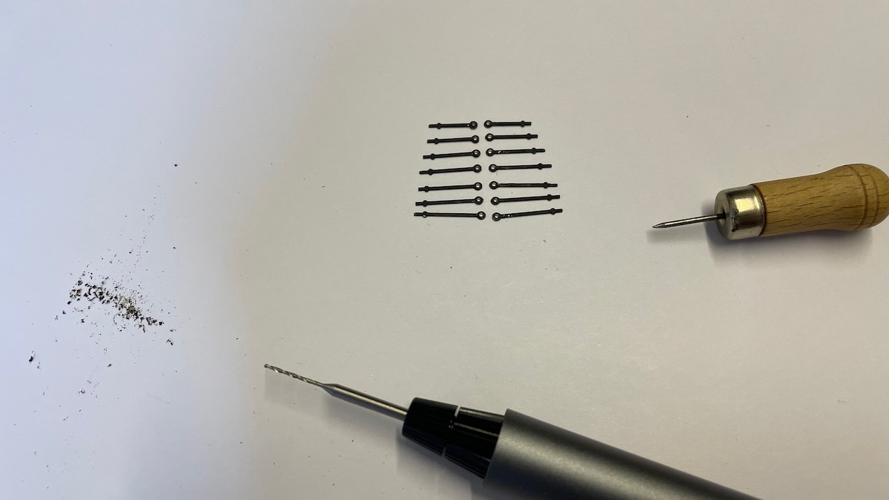
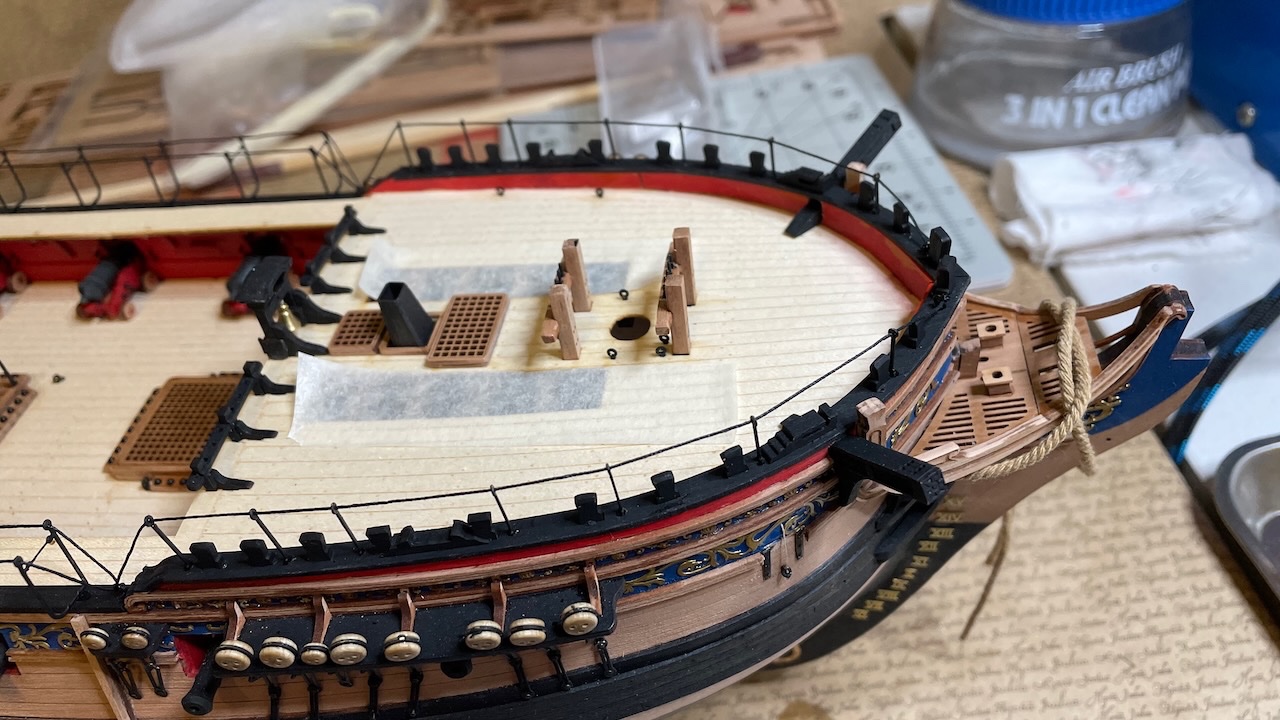
Build Day 72: 1,5 hours / Total 164 hours Photo 615: Waist Hammock Cranes and Waist Stanchions. Like before, I needed to use a 0,5 mm drillbit to open up the holes where the thread will go through. I still use a drop of CA glue to stiffen the end of the thread to help insert easily. Needless to say, I will retouch later the paint peeled of from the parts during process. Photo 616: Though not seen in the manual photos, according to the plans the Waist Stanchions are to be rigged with a 35mm long natural thread. I guess you grab them to help climb the ladders to the deck. Photo 617: Glued and rigged. I also opened the holes using 0.8 mm drillbit to fit the parts. By the way it is a good approach to treat these holes mainly as a reference where to drill than assuming as ready to fit holes, since all the paint, varnish and glues usually clog them up during construction. Photo 618: Forecastle Stanchions and drill dusts. Photo 619: Glued and rigged.
- 426 replies
-
- 6
-
-
- Vanguard Models
- Sphinx
- (and 1 more)
-
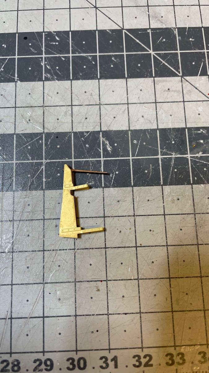
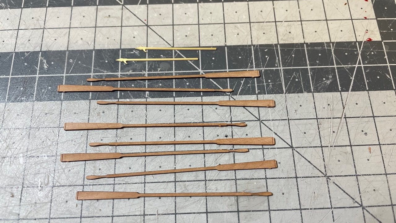
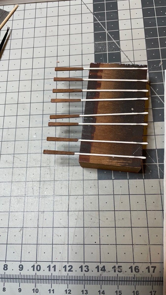
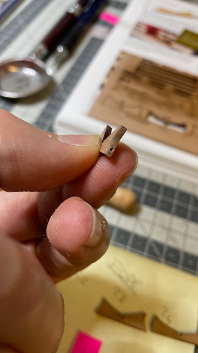
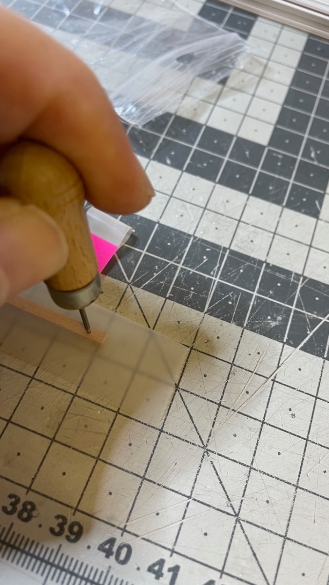
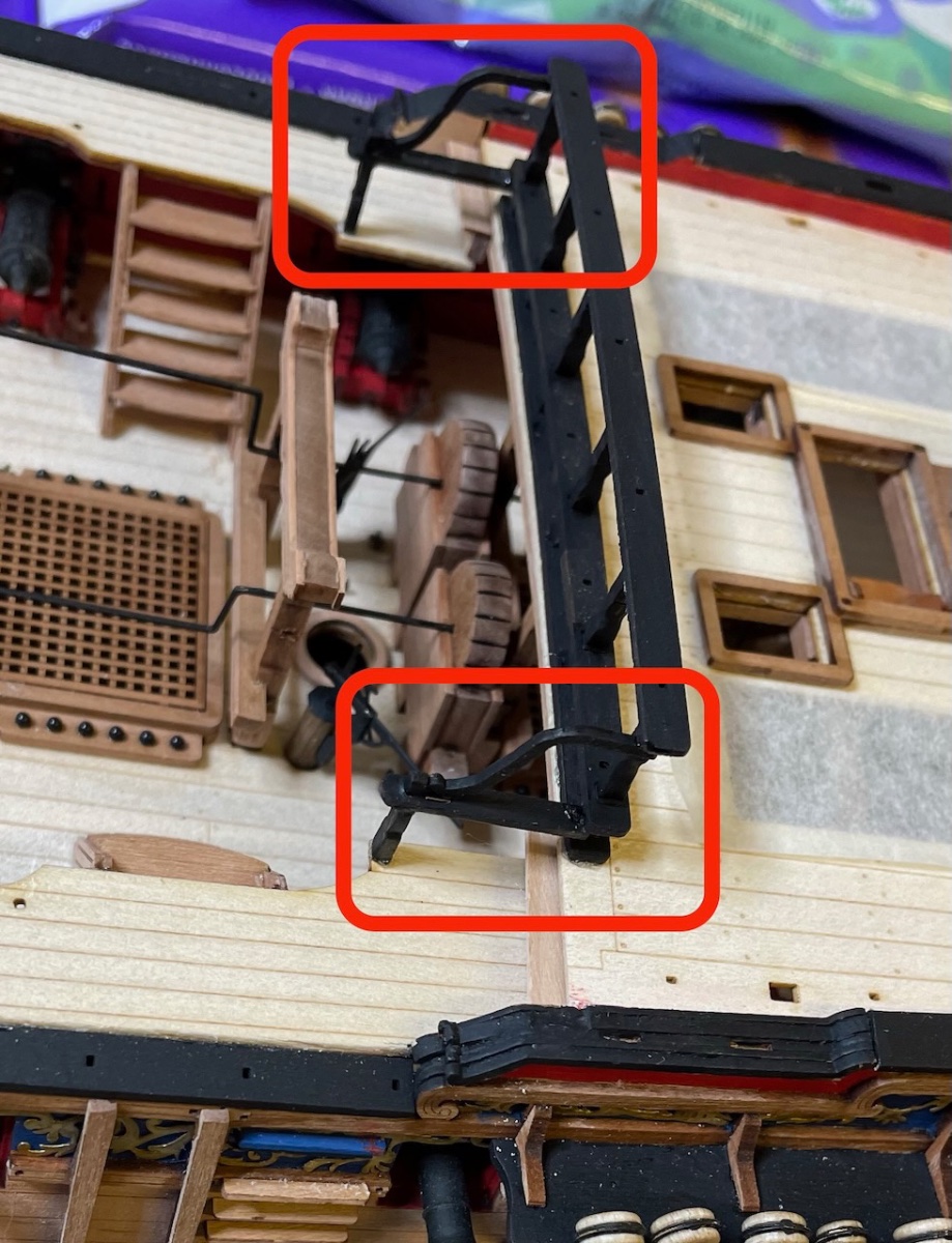
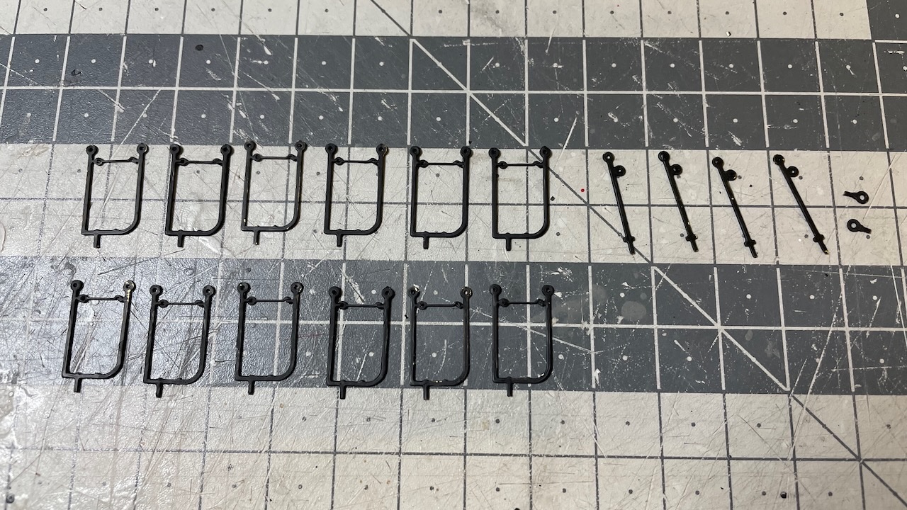
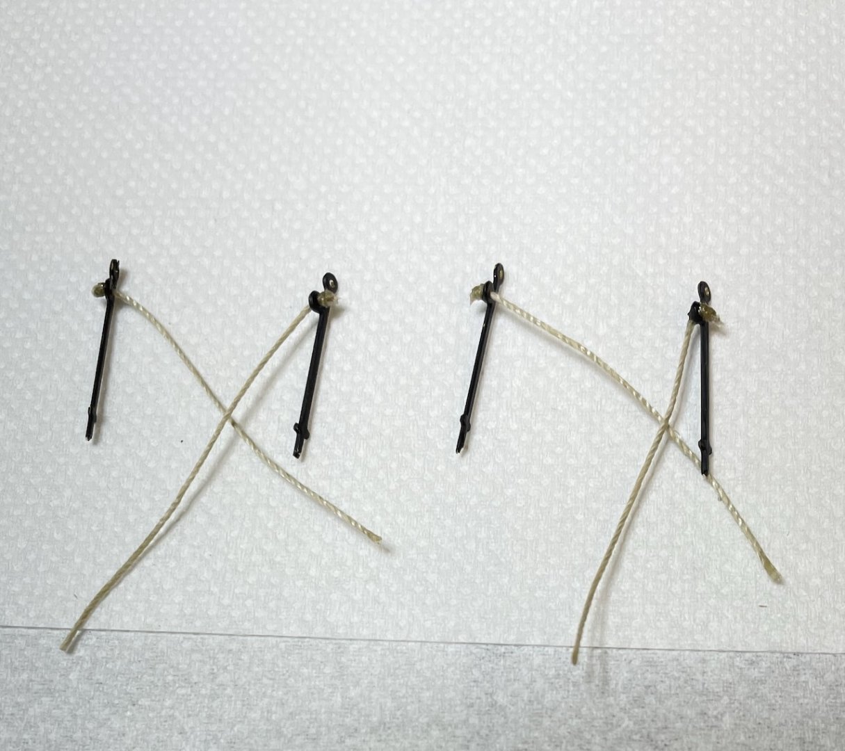
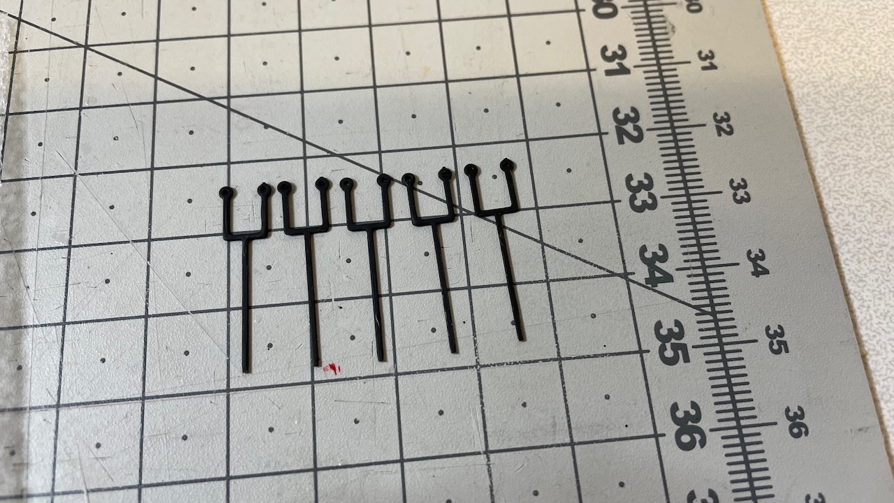
Build Day 71: 1 hours / Total 162.5 hours Today Ladderway Stanchions and Quarterdeck Breast Rail Hammock Cranes. Photo 611. Ladderway stanchions. Quite straightforward. Photo 612. Painted (while on sheet) and removed the Quarterdeck Breast Rail Hammock Cranes. They look like Poseidon's spear to me Photo 613. I needed to open up the holes a little, mostly due to clogging by paint. Luckily I happen to have a suitable drillbit with a long business end, that will drill straight through both holes st the same time. Photo 614. All in place and rigged. That's all for today. Thanks for watching!

- 426 replies
-
- 8
-
-
- Vanguard Models
- Sphinx
- (and 1 more)
-
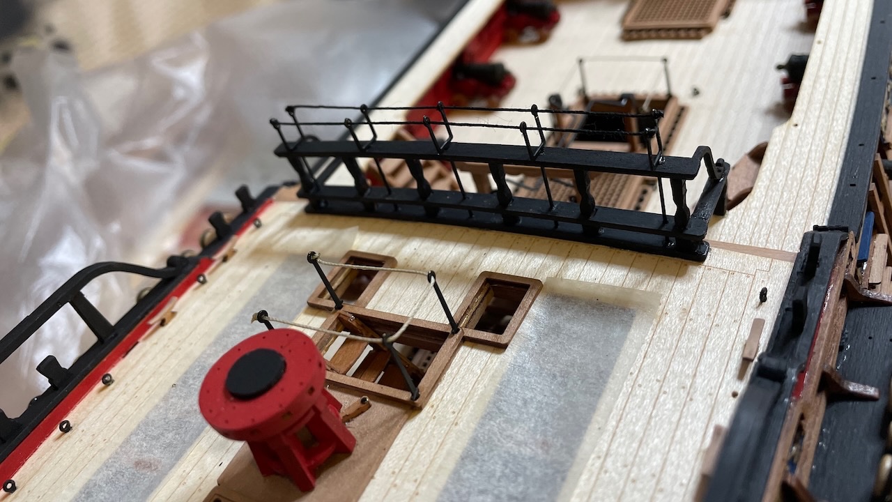
Photos 607-610: Preperation of boat cradles. Altogether six (two for each boat). Their places are engraved on the beams, if you have noticed. Work consists of cleaning the laser char, inserting the painted eyelets and finally gluing them on the cross beams. These constructions will wait aside for now so that they won't impede rigging work. That's all for today. Thanks for watching!
- 426 replies
-
- 5
-
-
- Vanguard Models
- Sphinx
- (and 1 more)
-
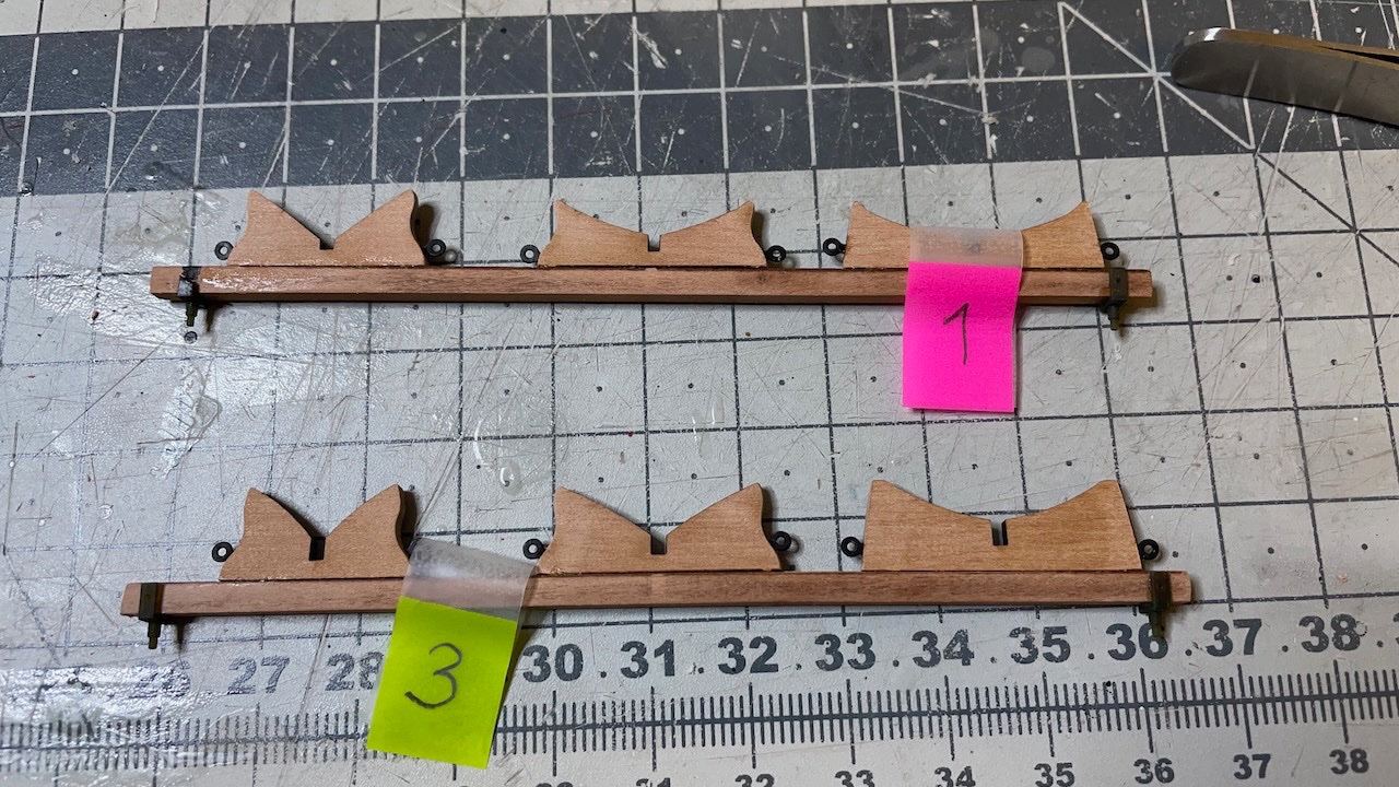
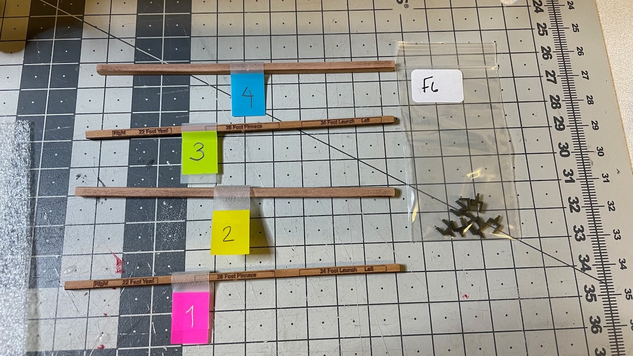
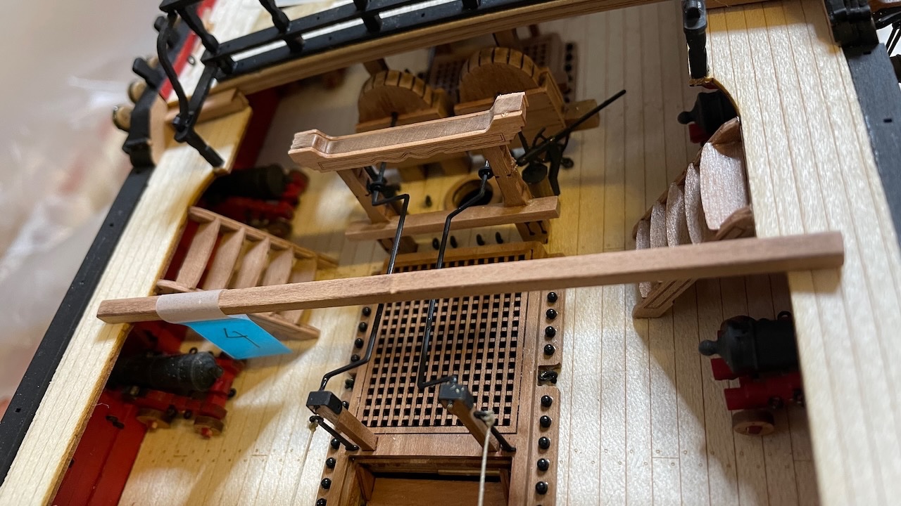
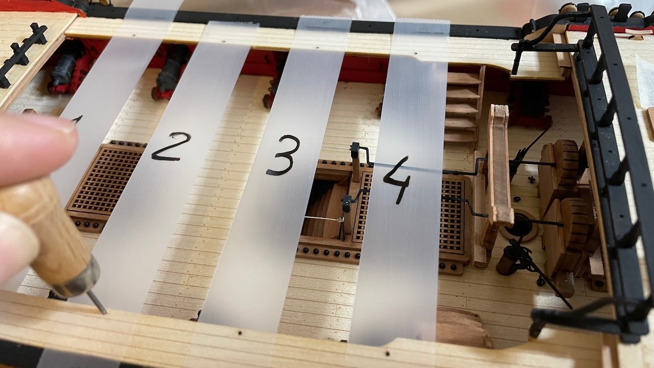
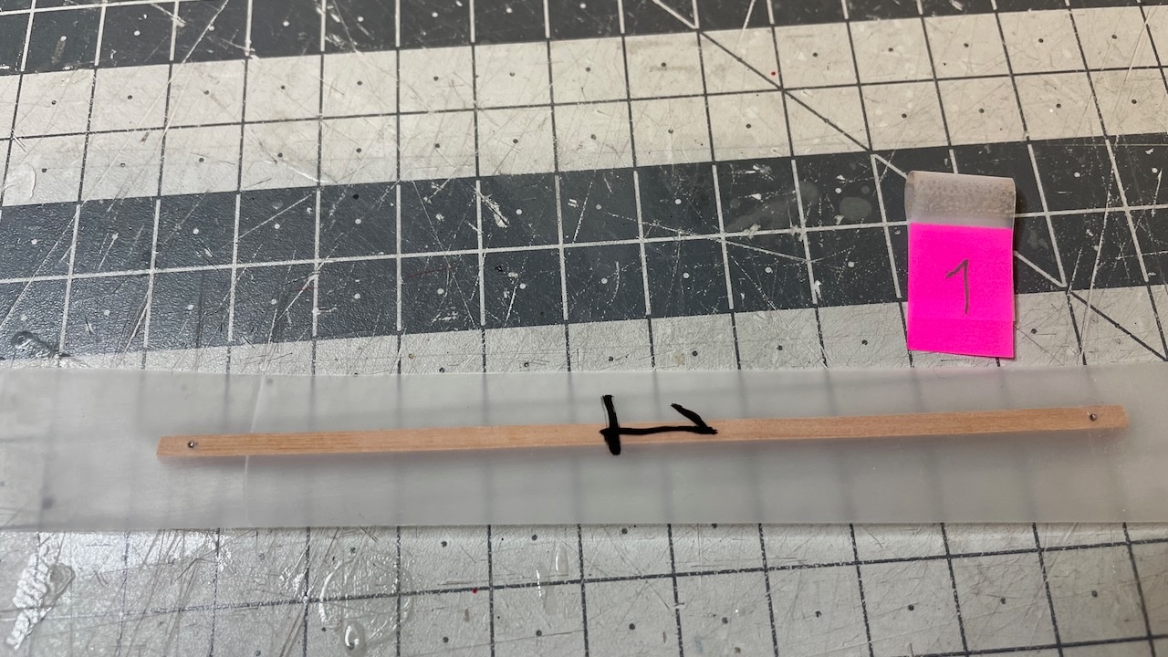
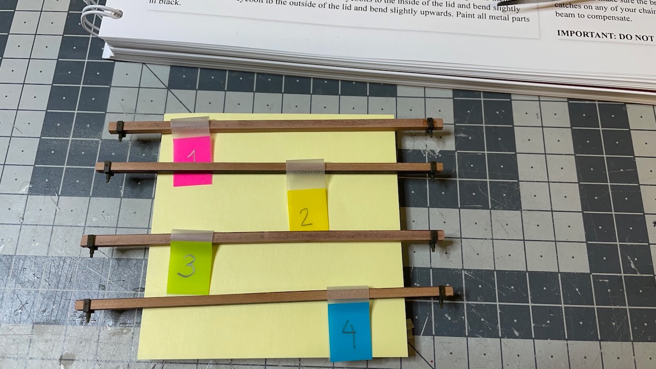
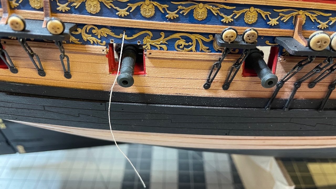
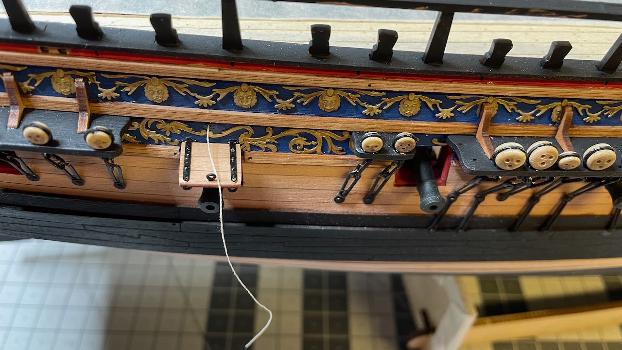
Build Day 70: 2 hours / Total 161.5 hours Boat Cross Beams construction. There are four of them. Each one has its own location on gangways and you must not mix. I labelled them with tape as well as on the plan. Photo 601: Photo 602: The 4th beam seemed to touch the chain pump handle which I had set in upright position (dry fit). I turned that pump handle a bit lower and also the other one to match with the position of the former. Photos 603-605: You'll need to transfer the holes on the gangways to the beams. These holes on the gangways will host the support brackets. This is how I did it with the help of transparent tape. Photo 606: The support brackets are in their places accurately. I still double checked the accuracy before gluing them on the beams.

- 426 replies
-
- 5
-
-
- Vanguard Models
- Sphinx
- (and 1 more)
-
No doubt! It is just the curiosity made me learn something new.
- 426 replies
-
- 2
-
-
- Vanguard Models
- Sphinx
- (and 1 more)
-
That explains it well, Jim! Thanks a lot for sharing the information!
- 426 replies
-
- 1
-
-
- Vanguard Models
- Sphinx
- (and 1 more)
-
At this point it made me wonder why only on some of the gun ports have lids. Did they not exist at all, or temporarily removed time to time, or was it just the kit design choice to expose the cannons better?
- 426 replies
-
- 1
-
-
- Vanguard Models
- Sphinx
- (and 1 more)
-
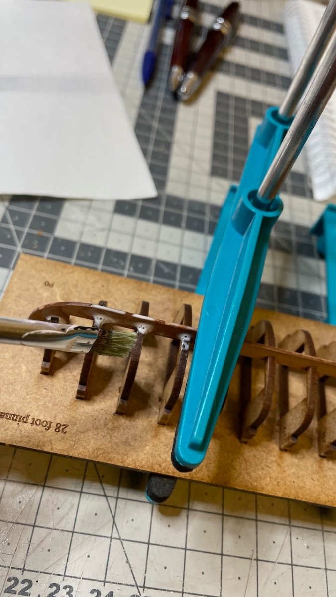
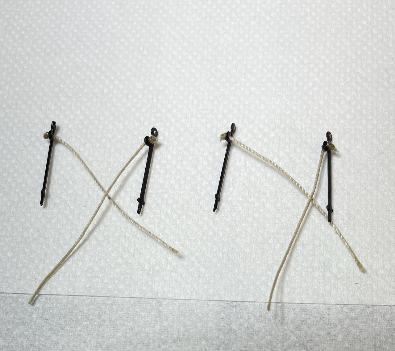
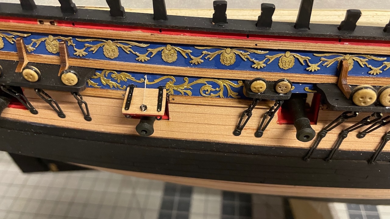
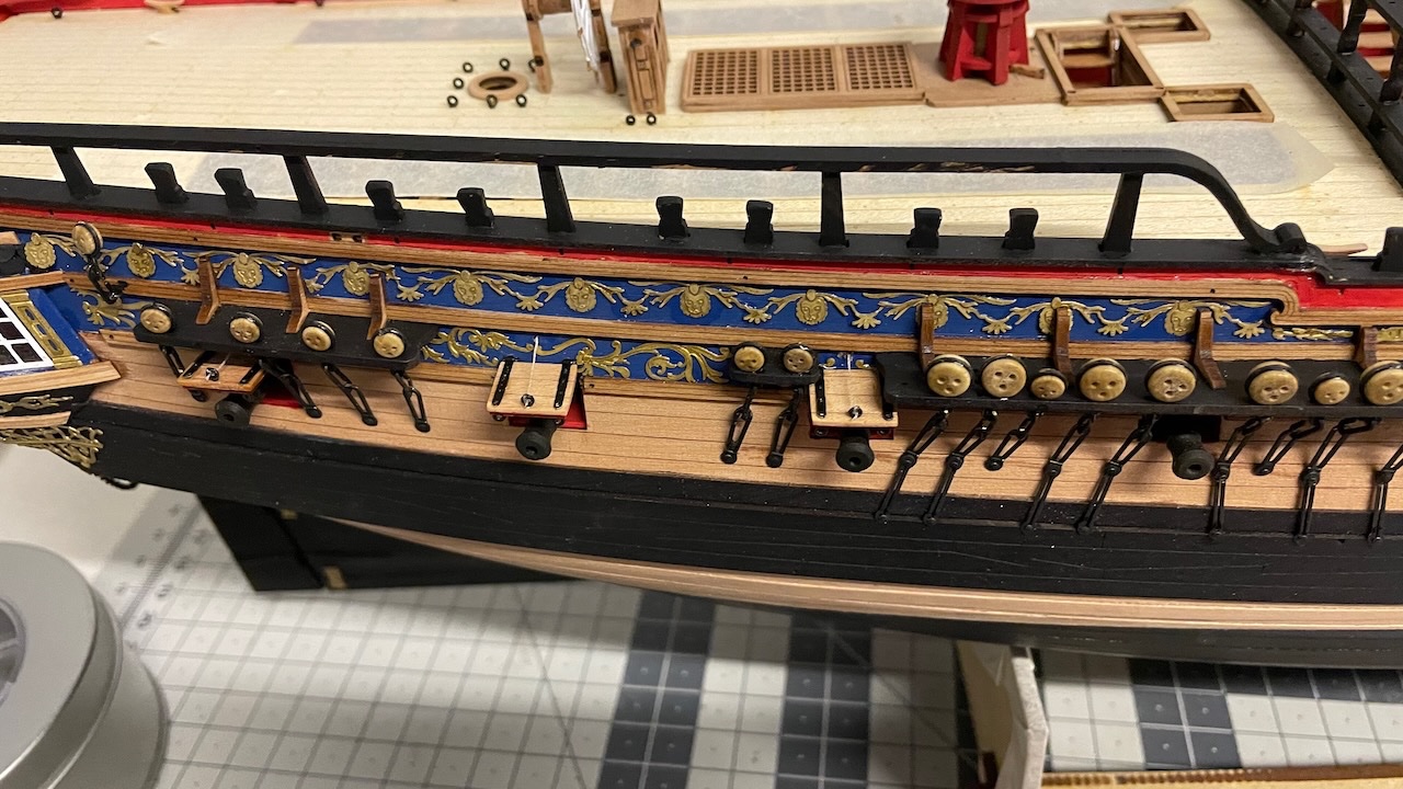
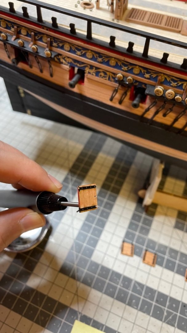
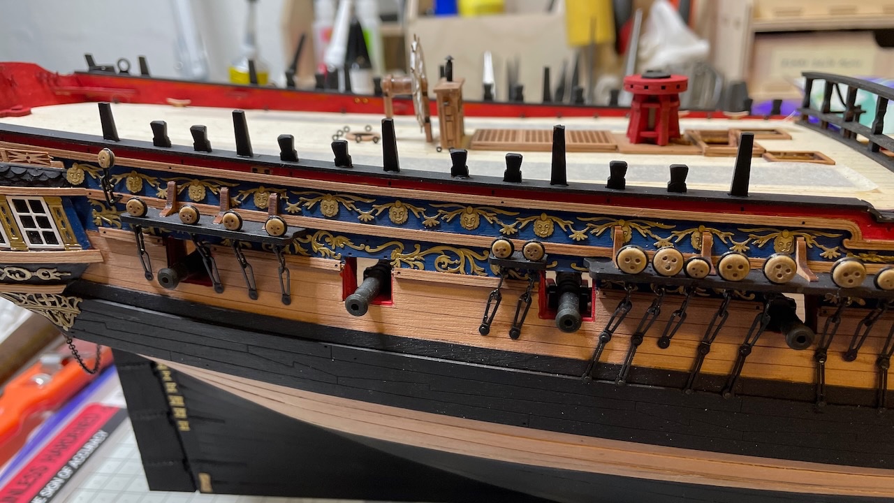
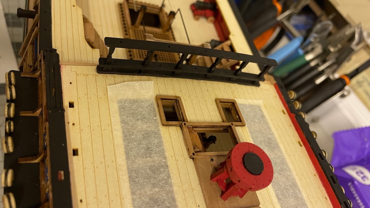
Here is my process: Photo 597: Apply some CA glue to the tip of the thread and insert it through the hole. The CA will hold it in place. Photo 598: Apply a drop of glue to each hinge end and insert them to their holes. Photo 599: Tie the thread, drop a tiny amount of CA and cut off the excess. Photo 600: All six lids in place (3 on each side). That's all for today. Thanks for watching!
- 426 replies
-
- 10
-
-
- Vanguard Models
- Sphinx
- (and 1 more)
-
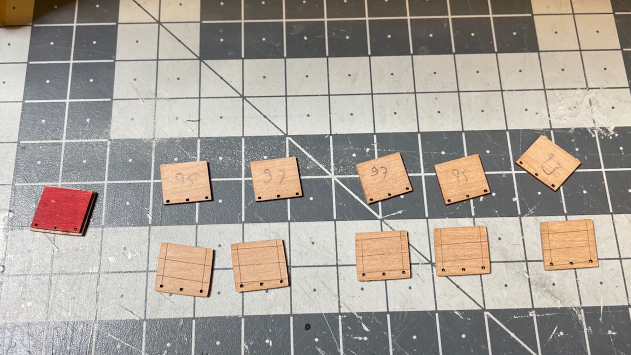
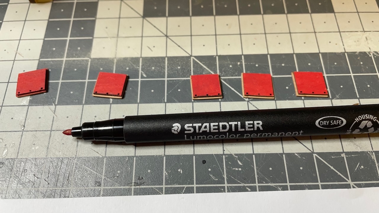
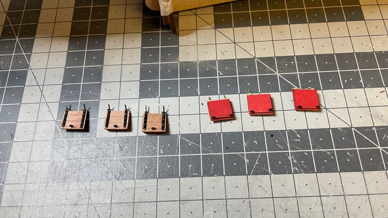
Build Day 69: 3 hours / Total 159.5 hours Today I prepared and installed the six gun port lids. It took about 3 hours. Photo 593: Labelled the part numbers after removing them from the sheet. I paid attention to keep them in the same alignment on the table as they were on the sheet as you should not really mix them. They are each to be glued to their own counterpart and they have their own place on the hull. I painted the back pieces to red already while they are on the sheet. Photo 594: Touching with a Staedtler Lumicolor for finishing the edges (see the piece on the left) Photo 595: Metal parts painted, fitted and matt varnish applied, waiting to dry. Photo 596: The tiny holes are easily clogged with varnish etc. I reopened them all using 0.5mm drill. That is 6 holes for each lid (3 on the lids and 3 on the hull).
- 426 replies
-
- 8
-
-
- Vanguard Models
- Sphinx
- (and 1 more)
-
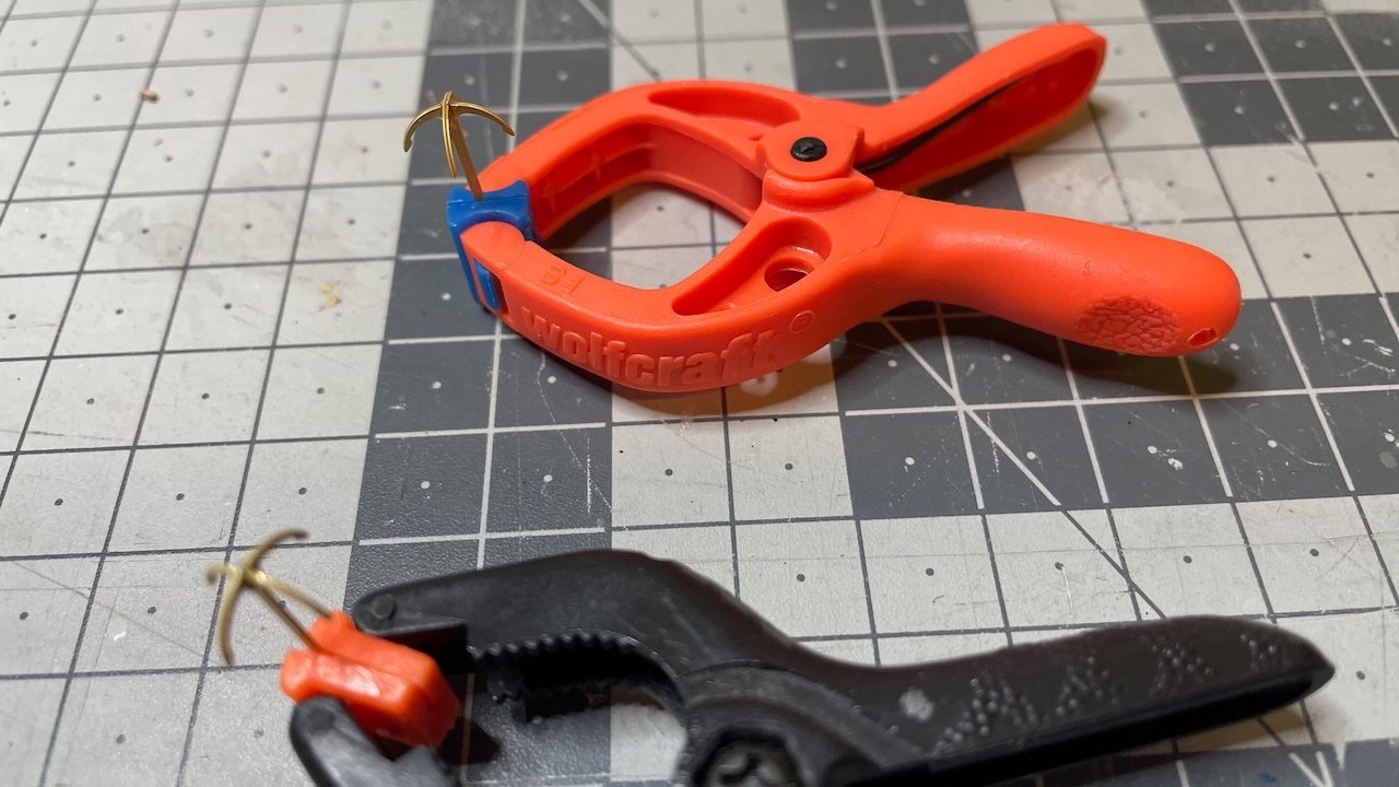
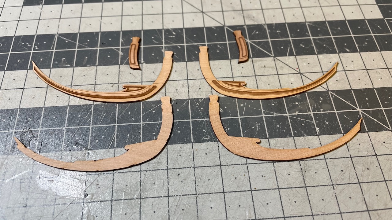
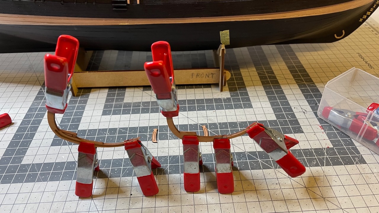
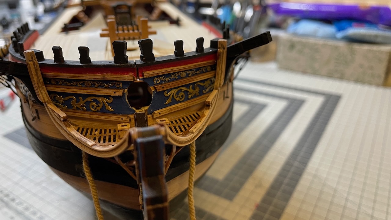
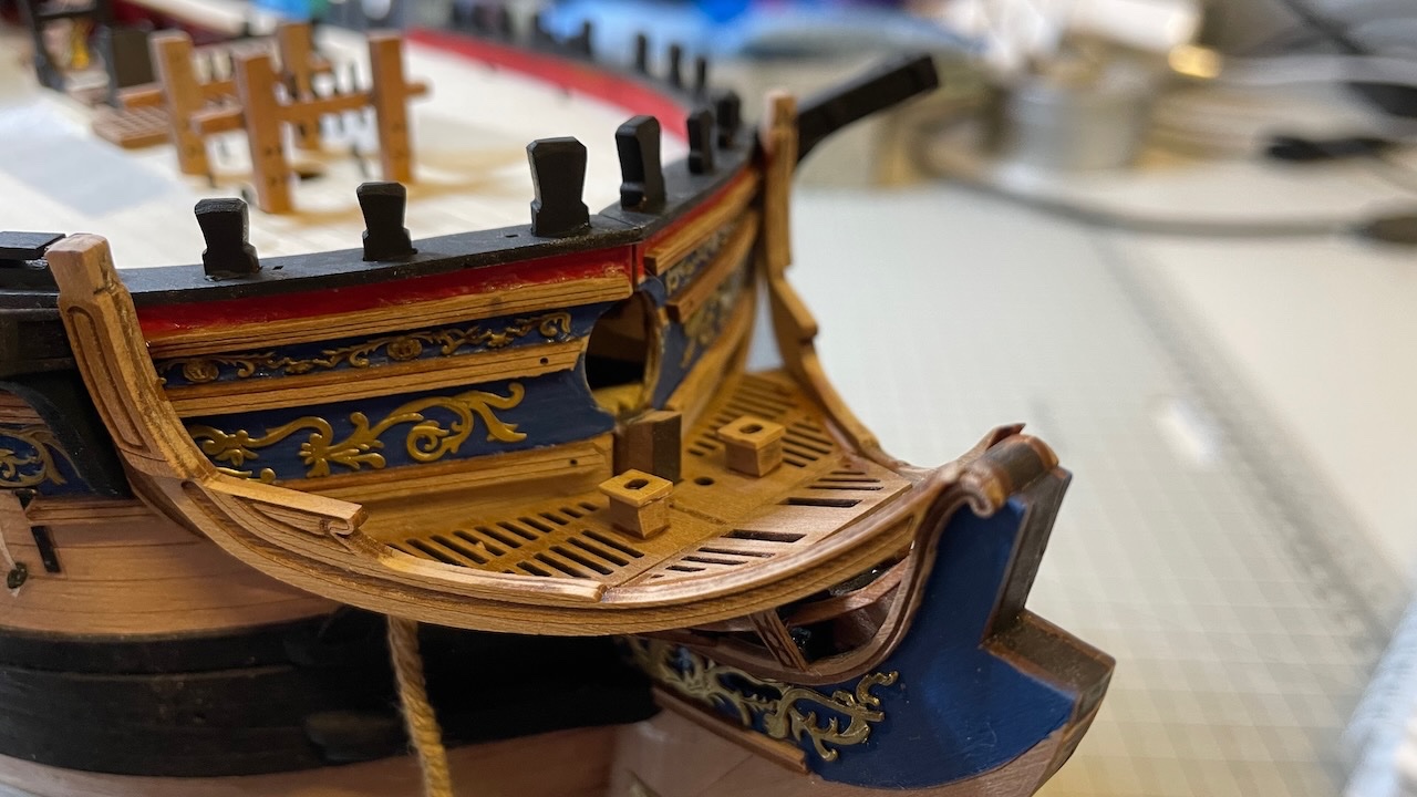
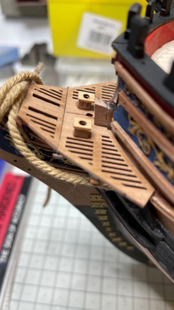
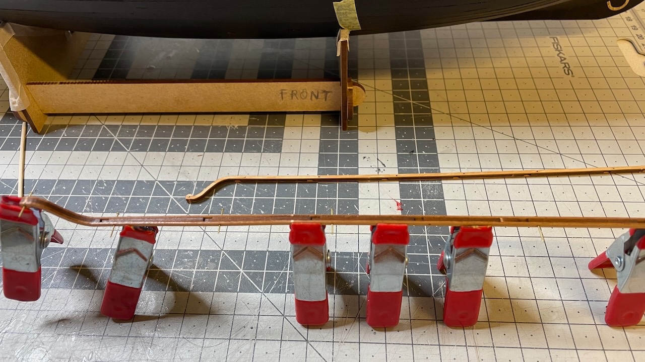
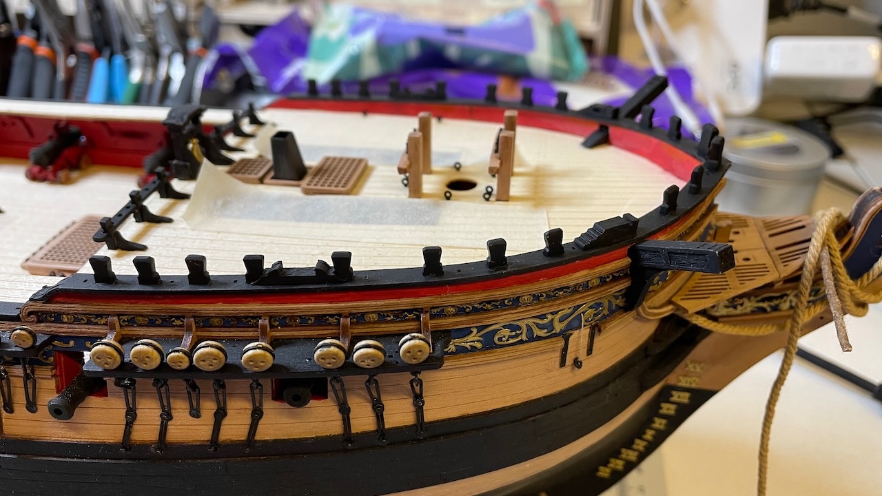
Build Day 68: 0.5 hour / Total 156.5 hours A short resume at build after a few weeks of break. Photo 587: Bow main rails, made of 3 parts each. Photo 588: Glued together. They look like wild goats with the clamps Photo 589: The head rail patterns under the bow gratings (i.e. parts 81,82,83) needed some sanding from the top in order to sit flush with them (Photo is from the manual). Photos 590-592: Glued in place. That's all for today. Thanks for watching!
- 426 replies
-
- 9
-
-
- Vanguard Models
- Sphinx
- (and 1 more)
-
Photos 585-586: Toilets. That's all for today. Thanks for watching!
- 426 replies
-
- 6
-
-
- Vanguard Models
- Sphinx
- (and 1 more)
-
Build Day 67: 1 hour / Total 156 hours Photos 582-584: Quarterdeck Fife Mail Rails. Nails used for aligning the three parts glued together. Glued by fitting the slots with the stanchions and then painted in black.
- 426 replies
-
- 4
-
-
- Vanguard Models
- Sphinx
- (and 1 more)
-
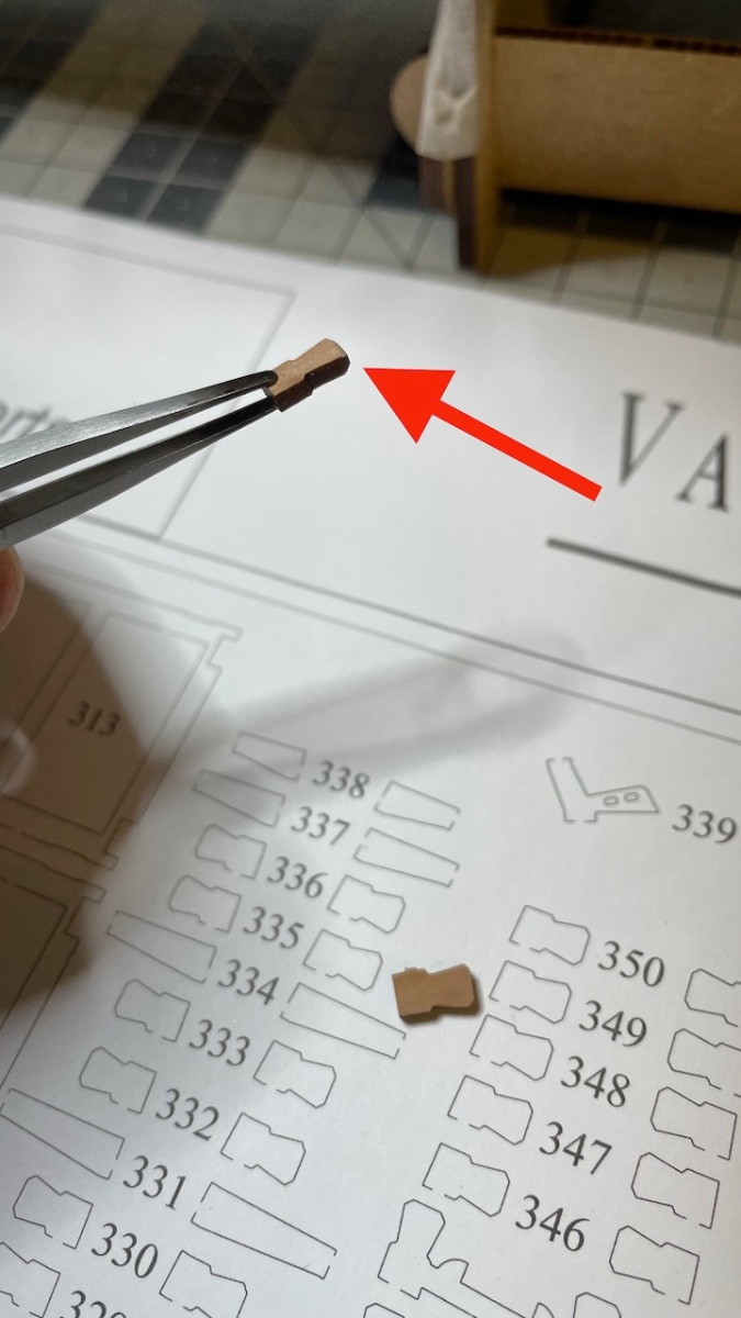
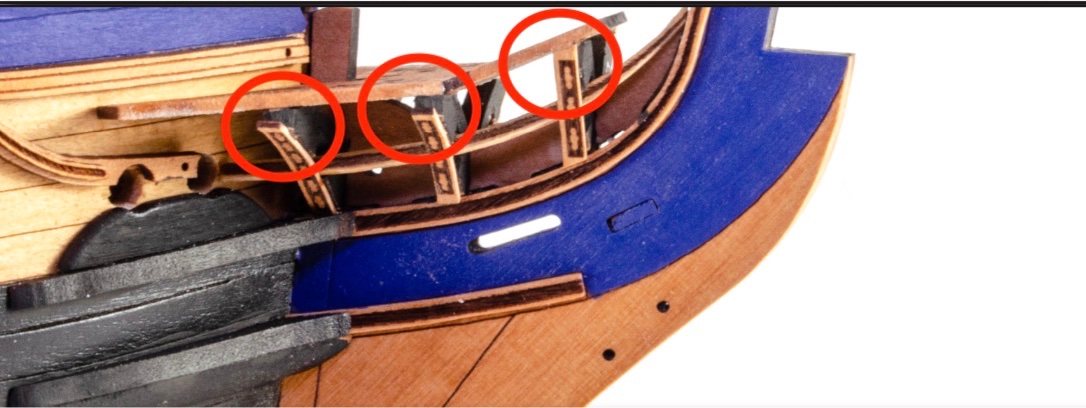
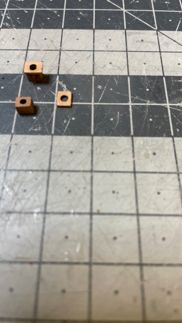
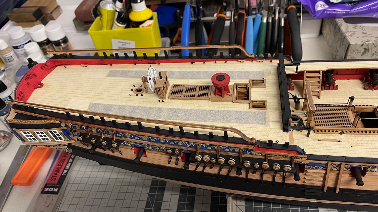
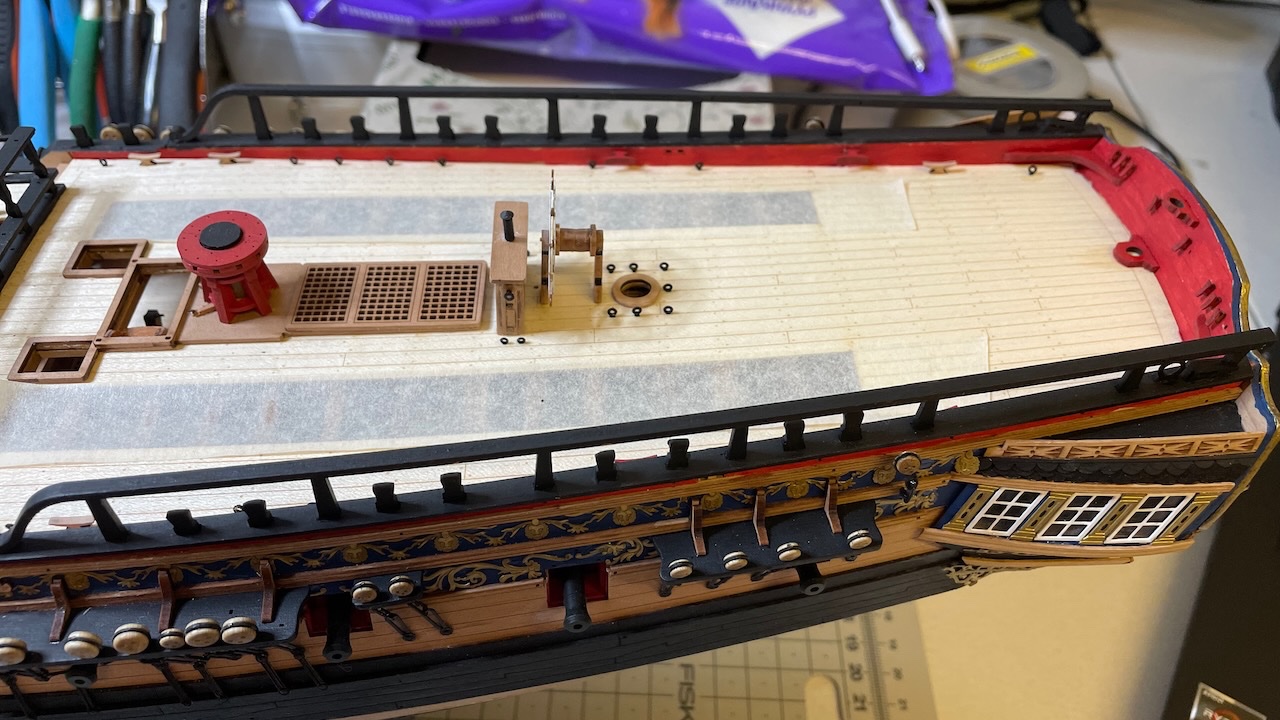
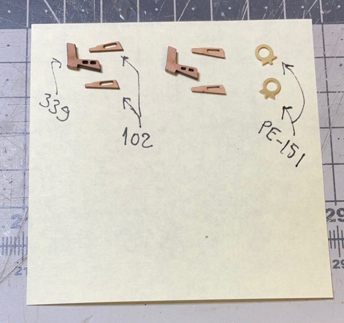
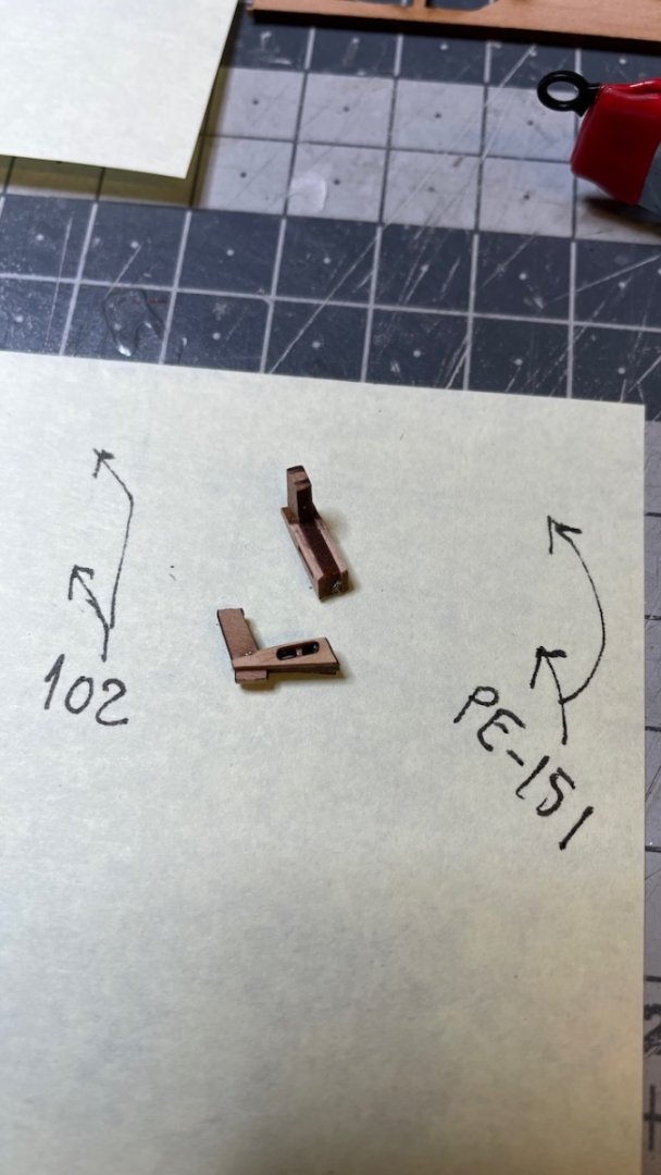
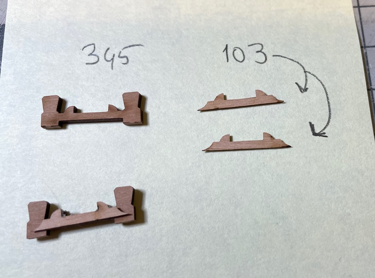
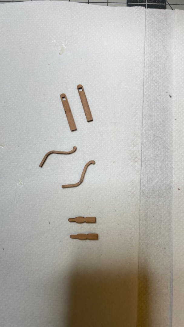
Build Day 66: 3 hours / Total: 155 hours Quarterdeck and Forecastle rail foundations. Below are several photos showing the progress with some notes on my experiences along the way. During the construction some steps are skipped in the manual. You'll need refer to the plan throughout the process and this is mentioned in the manual. Also keep the sheet with parts list close to yourself as the rail parts are so similar you can easily lose track of part numbers. I suggest you keep the parts on the wood sheet until you use them. Photo 574: Timberheads top section rounded from the inner and outer sides. Photos 575-577: One thing not in the instructions but shown in the Plan. Glue parts 102 on either side of 339. Also glue PE-151s in their places. Photo 578: Similarly glue parts 103 on either side of part 345. Photos 579-581: All rail elements glued and painted to black. That's all for today. Thanks for watching!

- 426 replies
-
- 5
-
-
- Vanguard Models
- Sphinx
- (and 1 more)
-
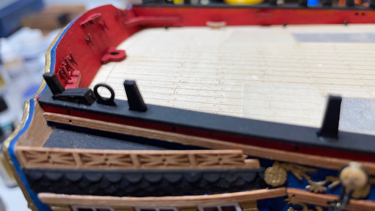
Build Day 65: 1 hour / Total 152 hours Photos 570-571: Remaining Quarterdeck breast rail components. Photos 572-573: Deck eyelets and cleats in place. These cleats are not painted hence they need laser chars removed. Eyelets will be visible in the future photos. That's all for today. Thanks for watching!
- 426 replies
-
- 7
-
-
- Vanguard Models
- Sphinx
- (and 1 more)
-
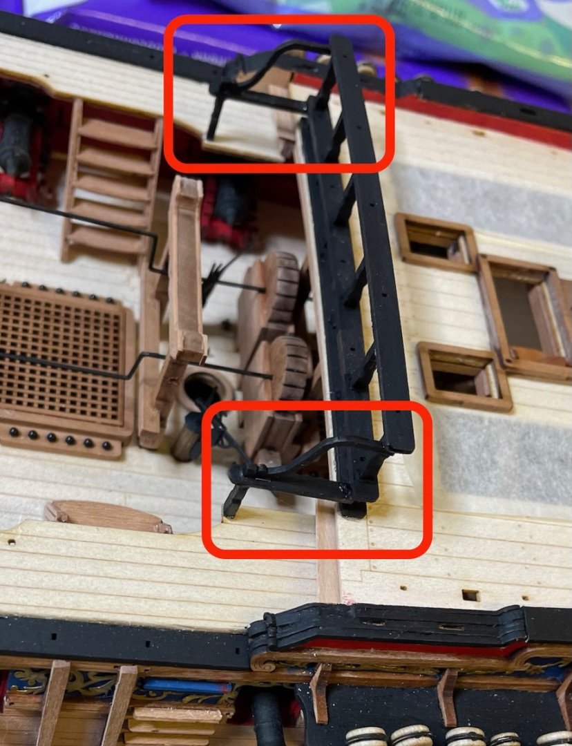
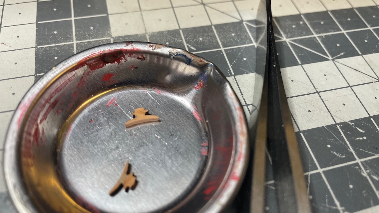
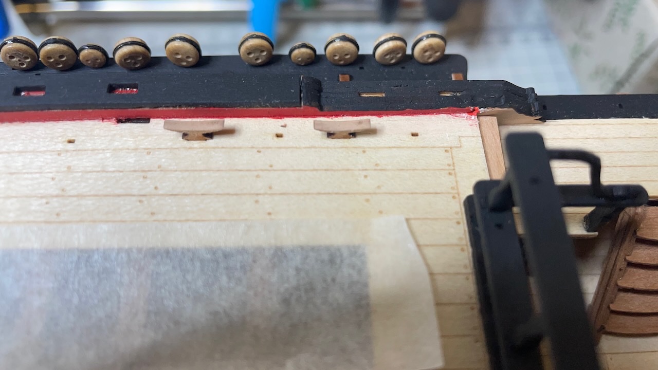
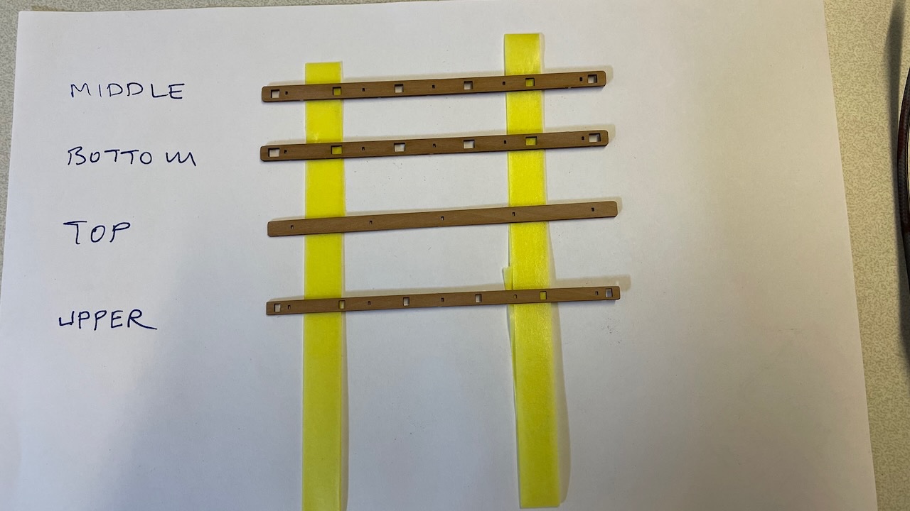
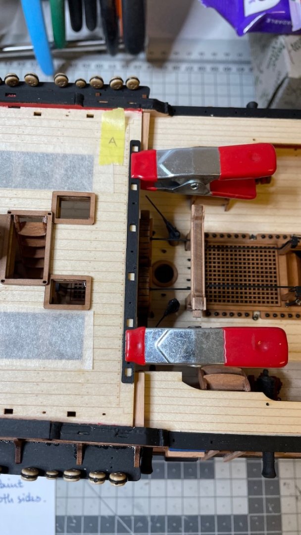
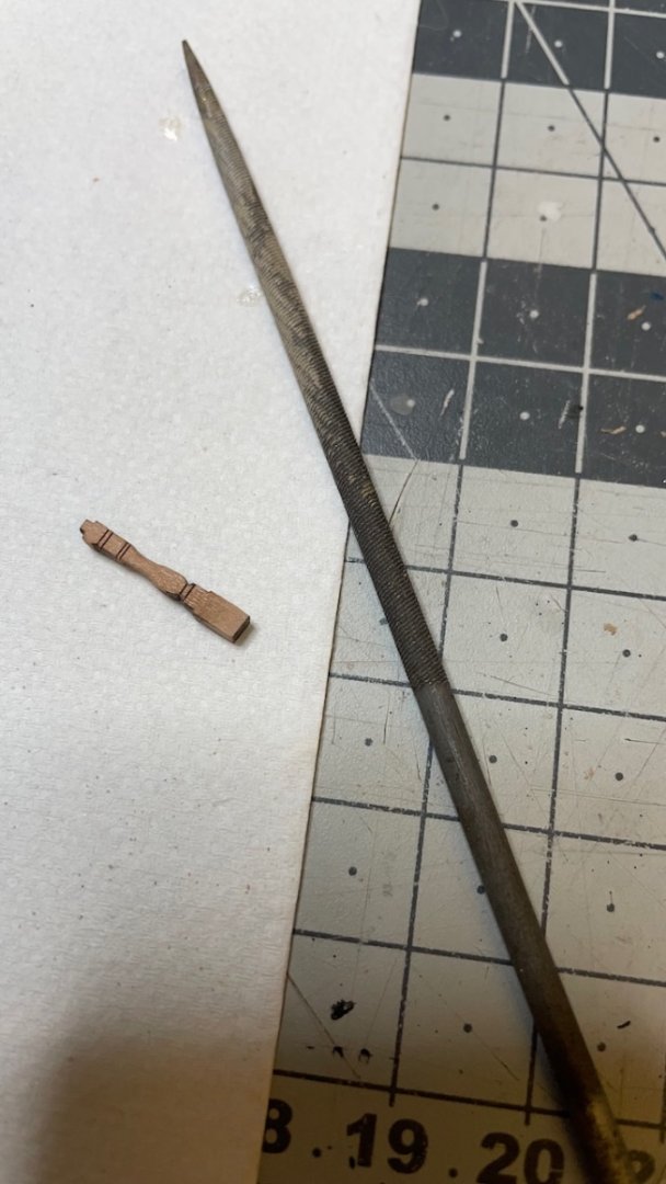
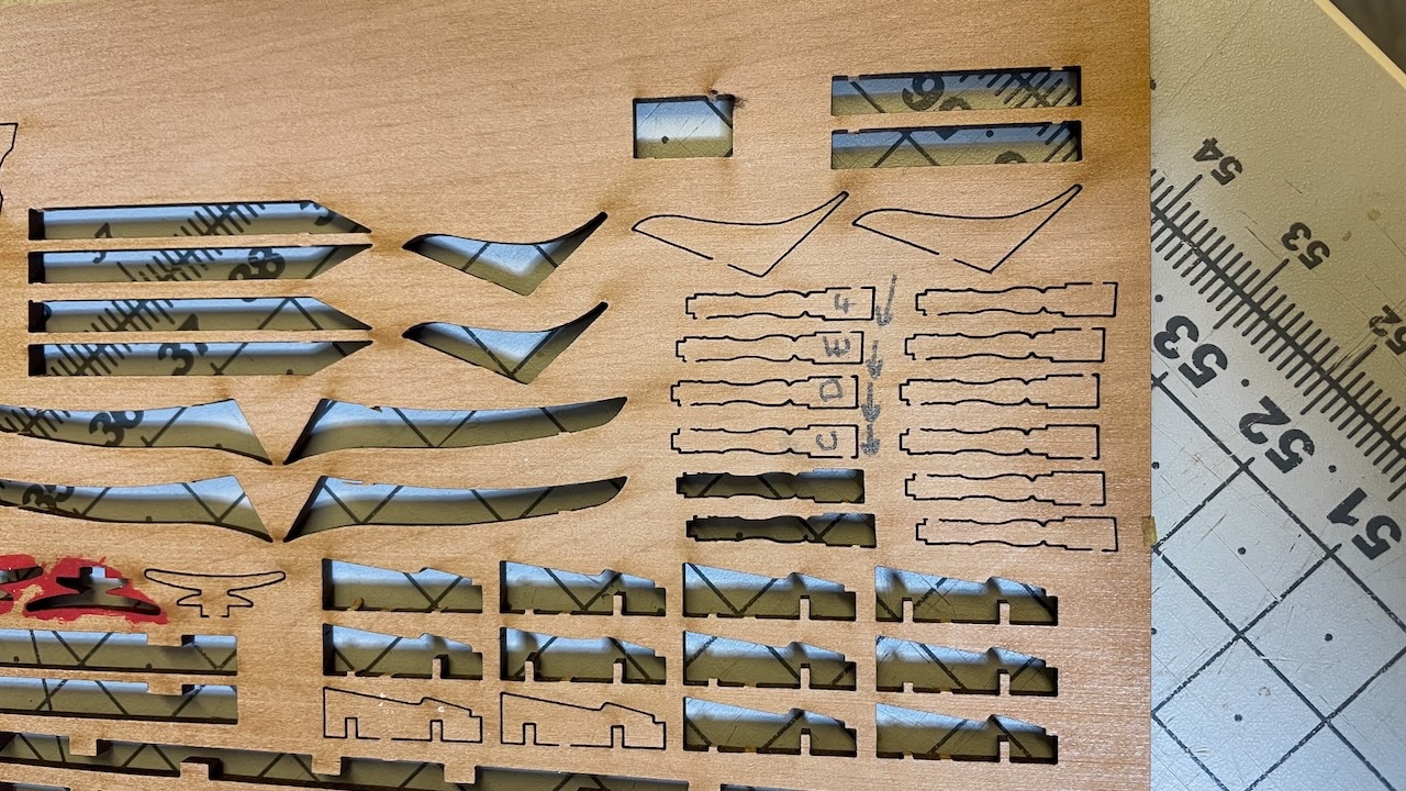
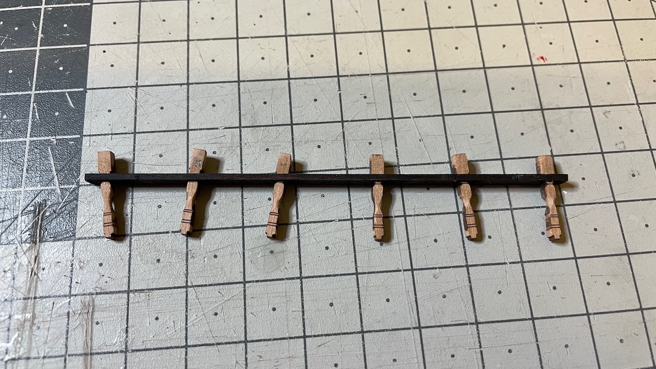
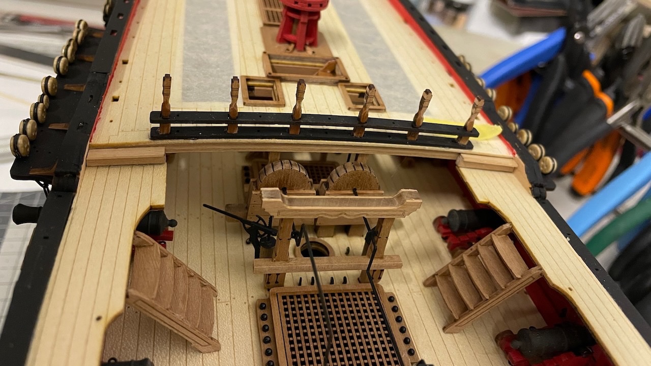
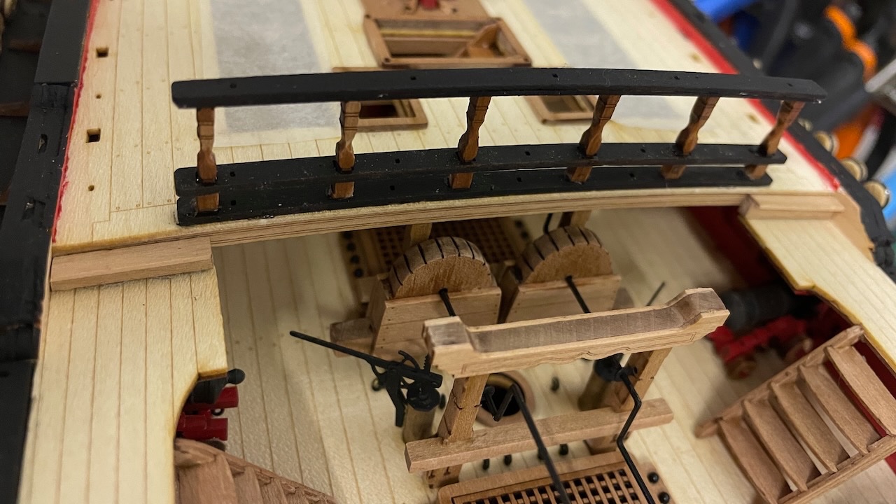
Quarterdeck breast construction. Photo 654: Parts removed and prepared for paint, labelled to avoid mixing them up. Photo 655: Lower rail in place. I referred to the plan to determine the order of the stanchions and marked with a tape the position of part A. Photos 656-657: The stanchions go A, B,..F. Though they are almost identical, they differ slightly in the bottom, where they follow the curvature of the deck. Photo 565: You'll need to round the "belly" of the stanchions in the shape of a round pillar. Here is one done. I used the file in the photo for this. Photo 566: I inserted the stanchions already to the middle rail before glueing them in their places. Note they are not glued to the middle rail yet. They move freely. This will allow me to make alignment adjustments easily. Photos 567-569: Stanchions and remaining rails are in place. Further, I painted the stanchions in black. That's all for today. Thanks for watching!
- 426 replies
-
- 8
-
-
- Vanguard Models
- Sphinx
- (and 1 more)
-
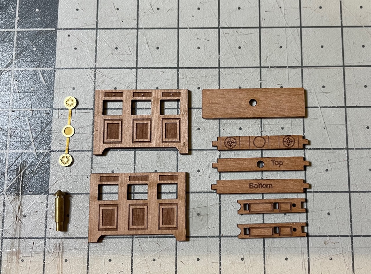
Photos 652-653: Binnacle in progress. Photos of the complete structure is missing at the moment.
- 426 replies
-
- 3
-
-
- Vanguard Models
- Sphinx
- (and 1 more)
-
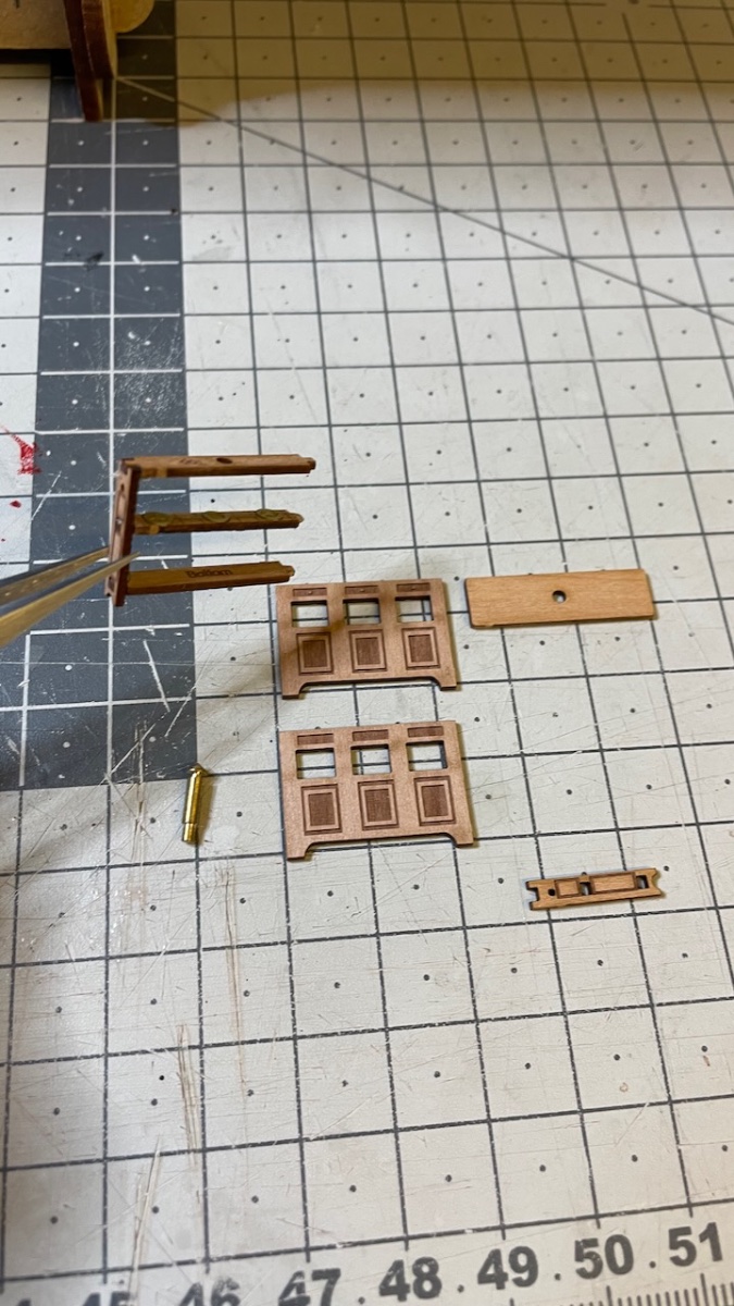
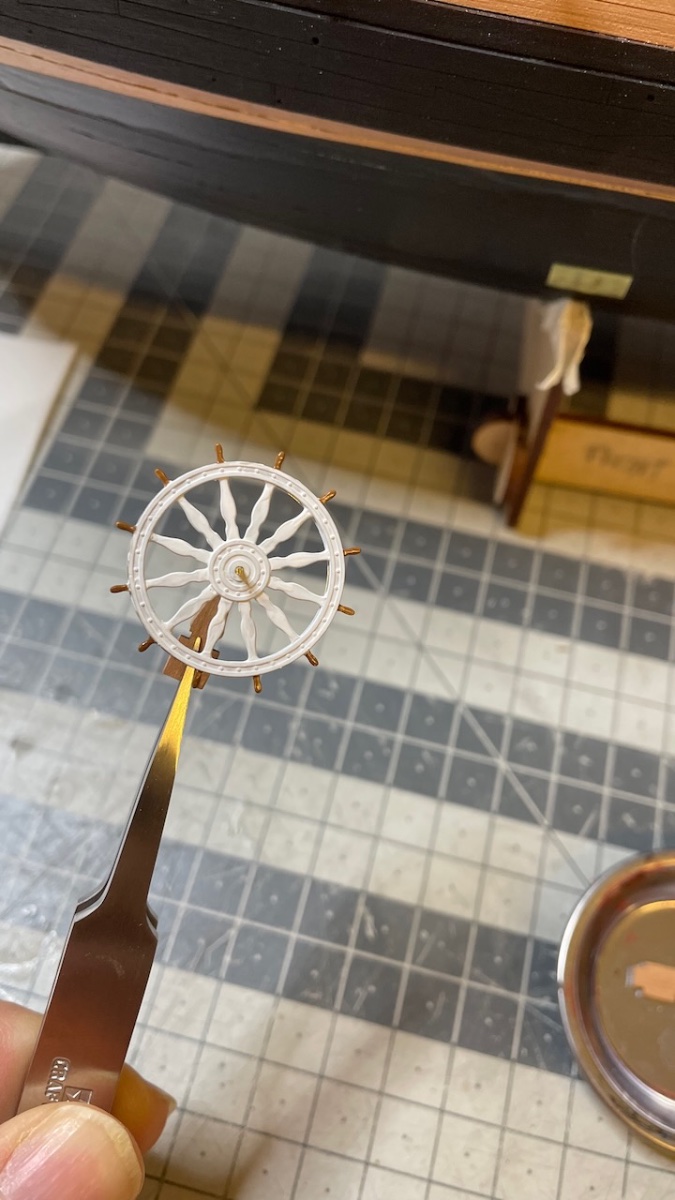
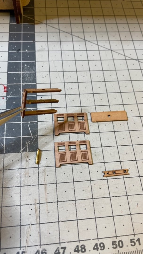
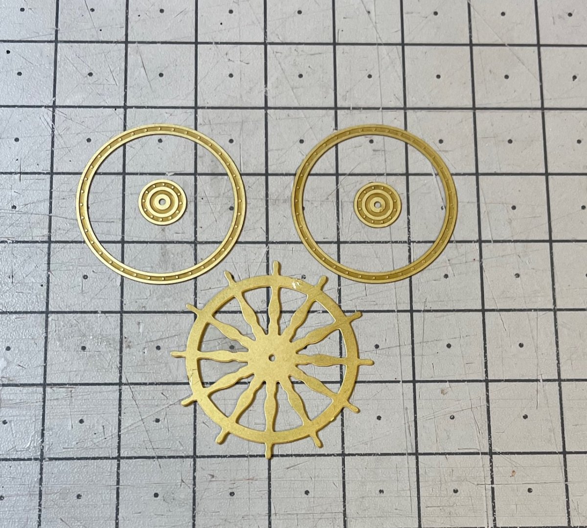
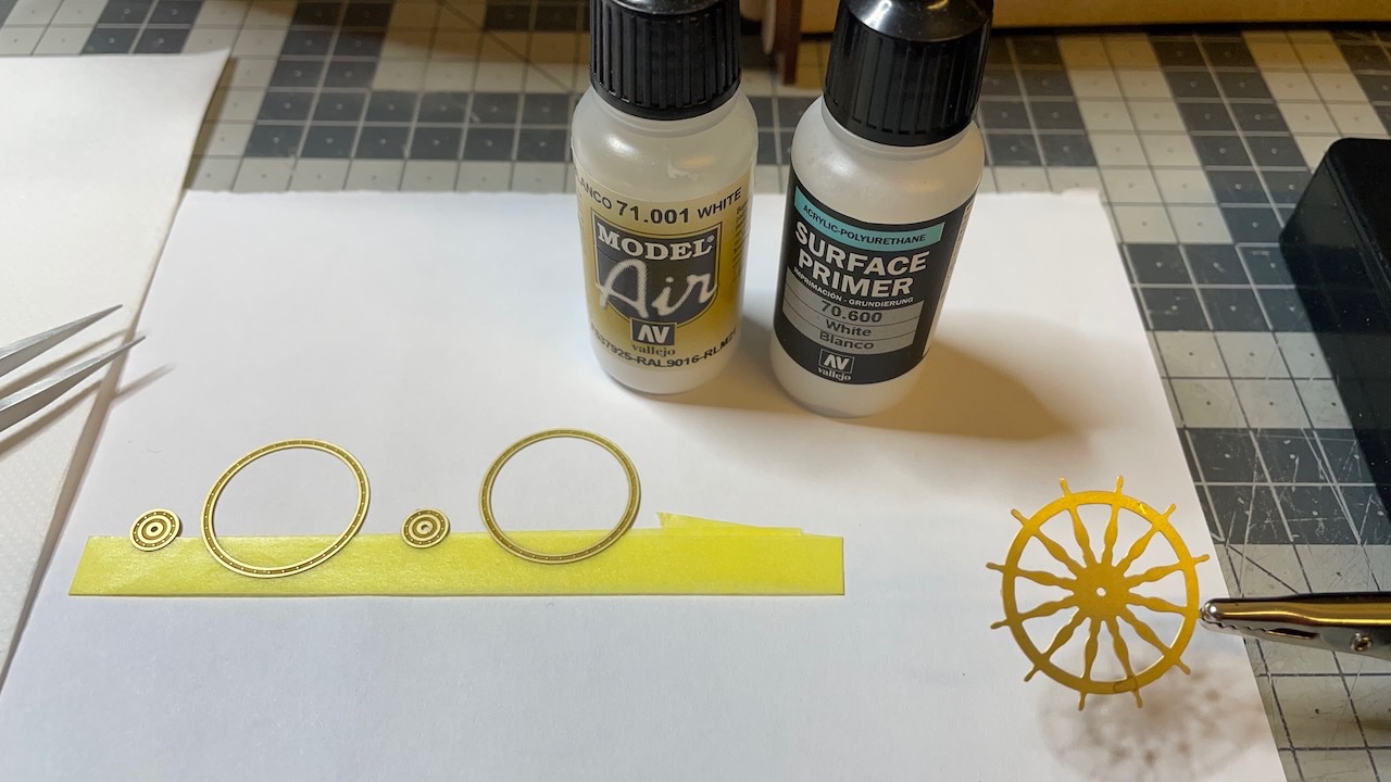
Build Day 64: 4,5 hours / Total 151 hours It was a productive Sunday today with 4,5 hours of build. I completed the Ship's Wheel, Binnacle and Quarterdeck Breast. I am writing this log after I have closed my workbench for the day and covered the model, and I have noticed that I didn't take any photos of the Wheel and Binnacle constructions in their place. I will take and post those photos later. Photo 648-651: Ship's wheel. I used white primer followed by the white paint. Once dry, I applied walnut color to the handles.

- 426 replies
-
- 3
-
-
- Vanguard Models
- Sphinx
- (and 1 more)
-
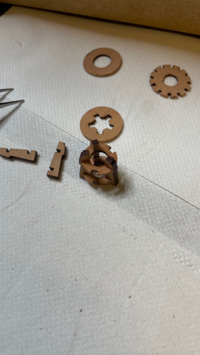
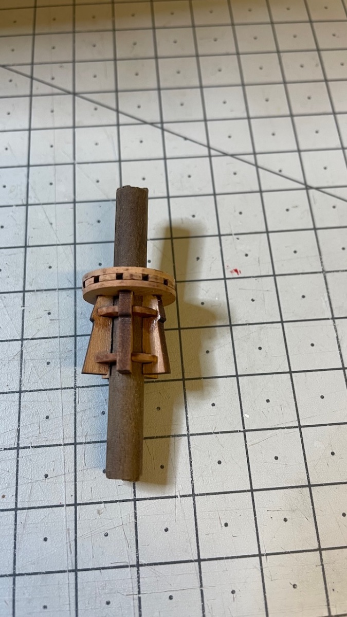
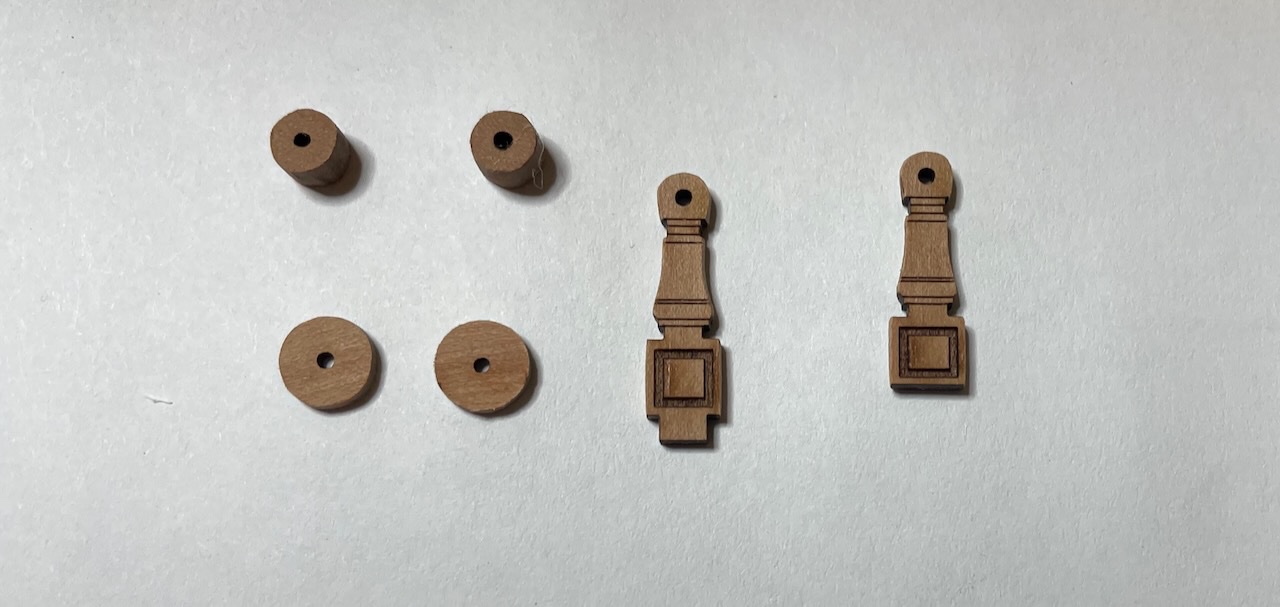
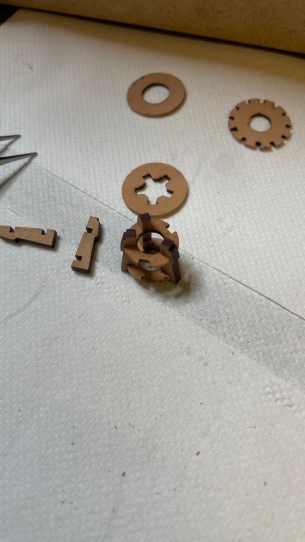
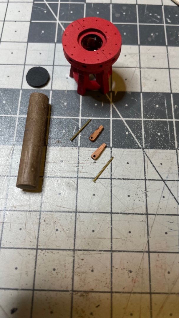
Build Day 63: 1 hour / Total 146.5 hours Photos 644-647: Yesterday I spent around one hour building and installing the upper capstan. The steps are similar to the previous one.

- 426 replies
-
- 3
-
-
- Vanguard Models
- Sphinx
- (and 1 more)
-
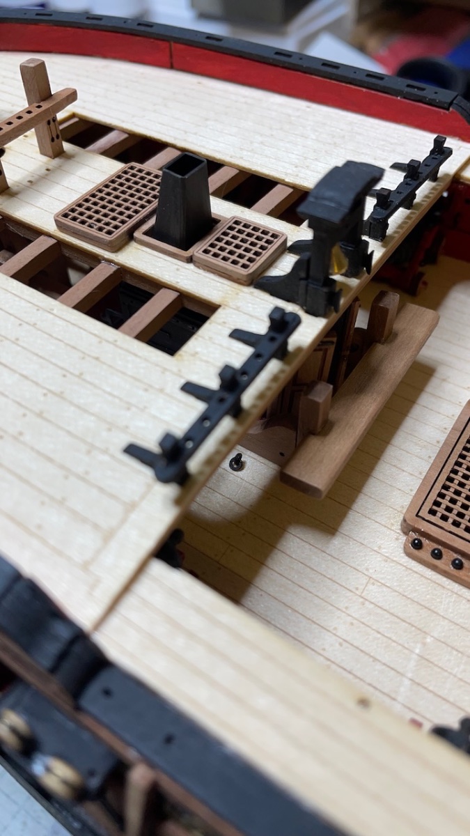
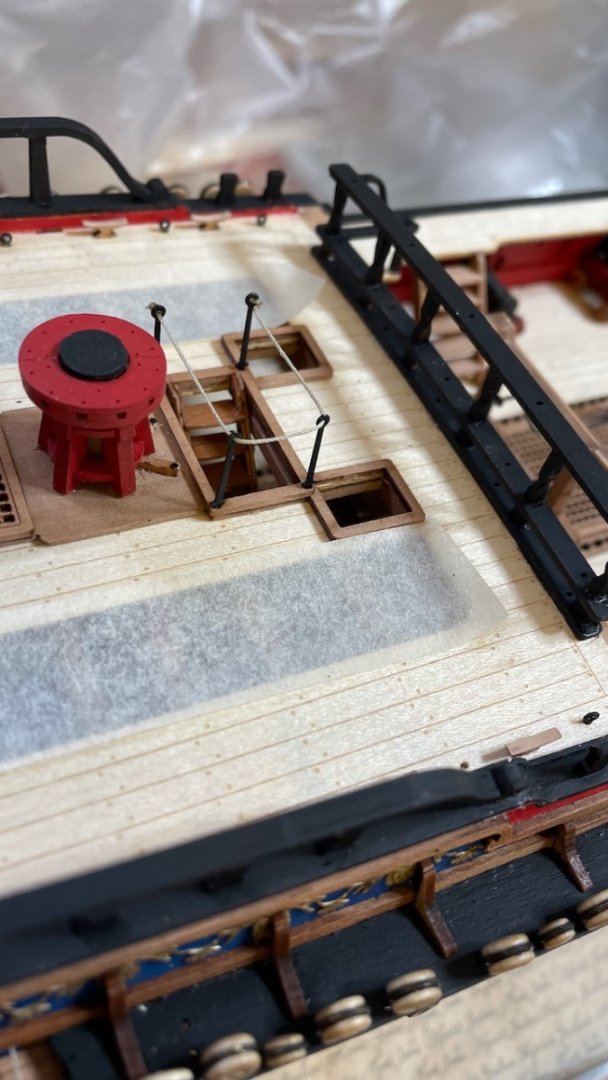
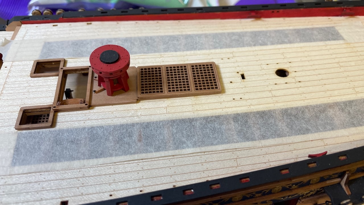
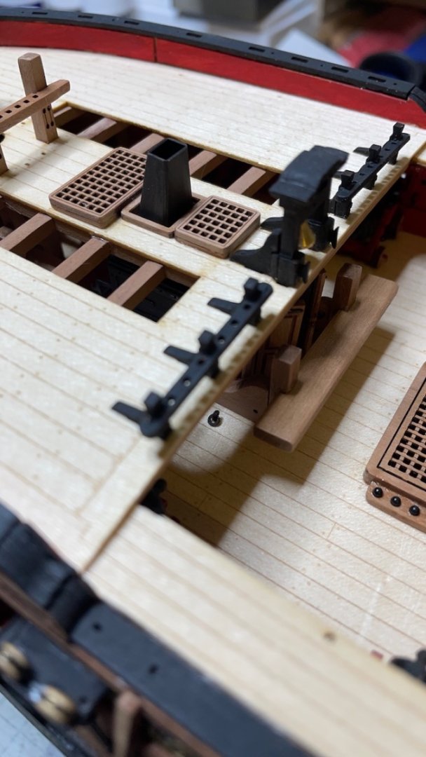
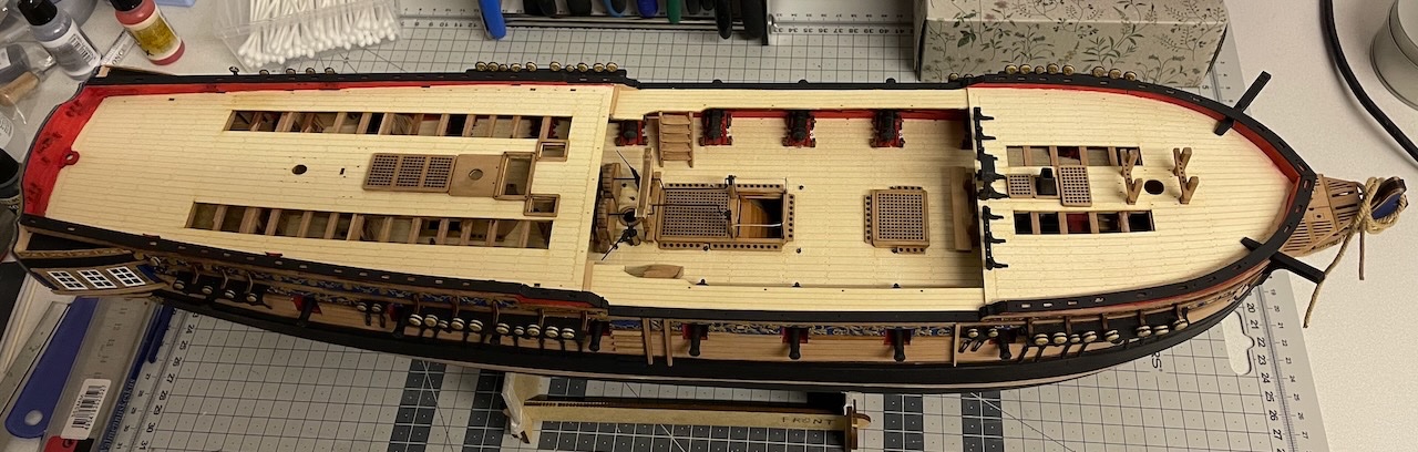
Photos 642-643: Ended the day by gluing the stove flue and Quarter deck gratings in place. I missed the slot on top of the stove due to some minor alignment errors, but I just removed off the socket on the bottom of the flue and glued it on top of the stove. No issues. That's all for today. Thanks for watching!
- 426 replies
-
- 6
-
-
- Vanguard Models
- Sphinx
- (and 1 more)