
Gbmodeler
-
Posts
465 -
Joined
-
Last visited
Content Type
Profiles
Forums
Gallery
Events
Everything posted by Gbmodeler
-
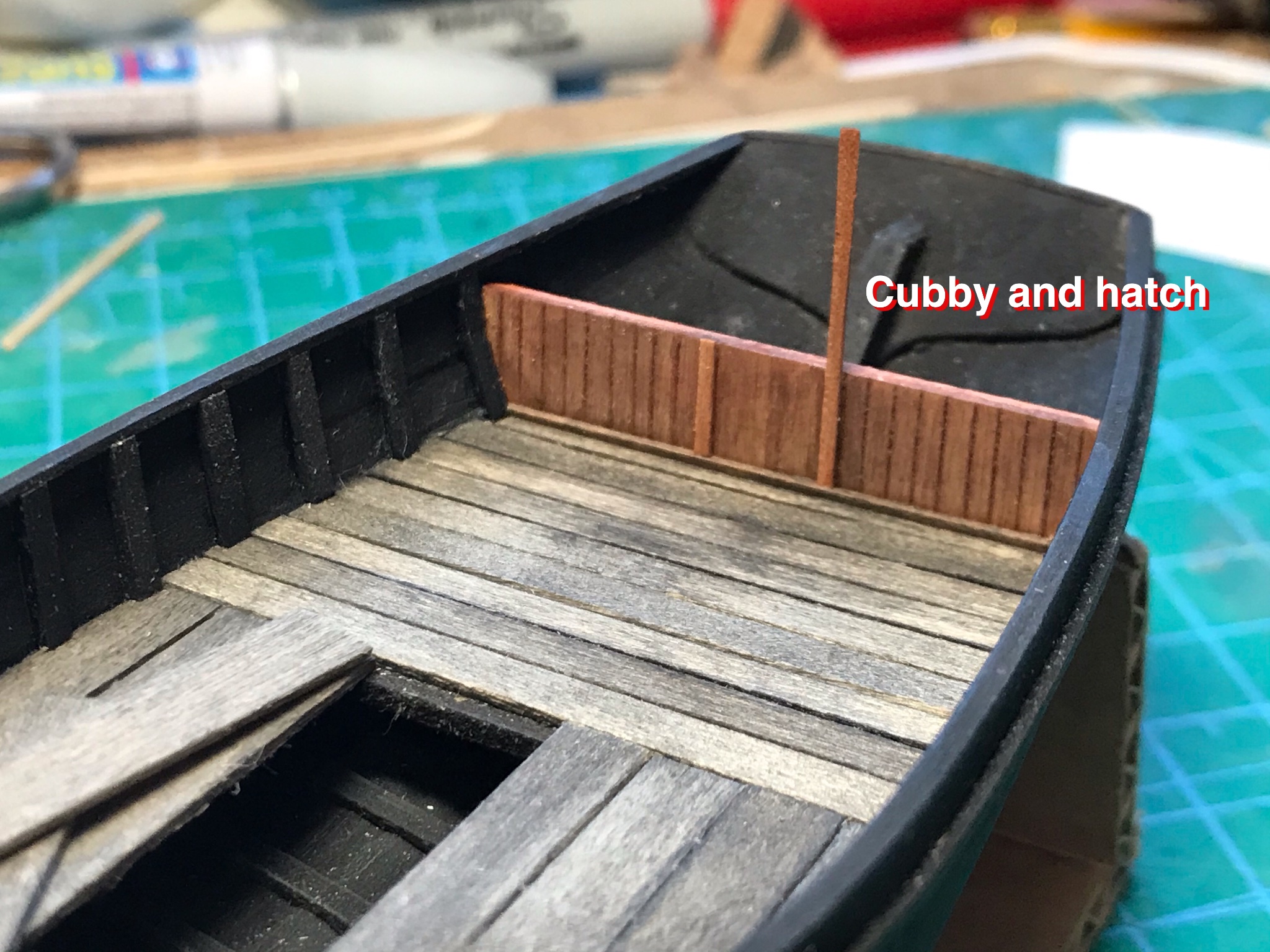
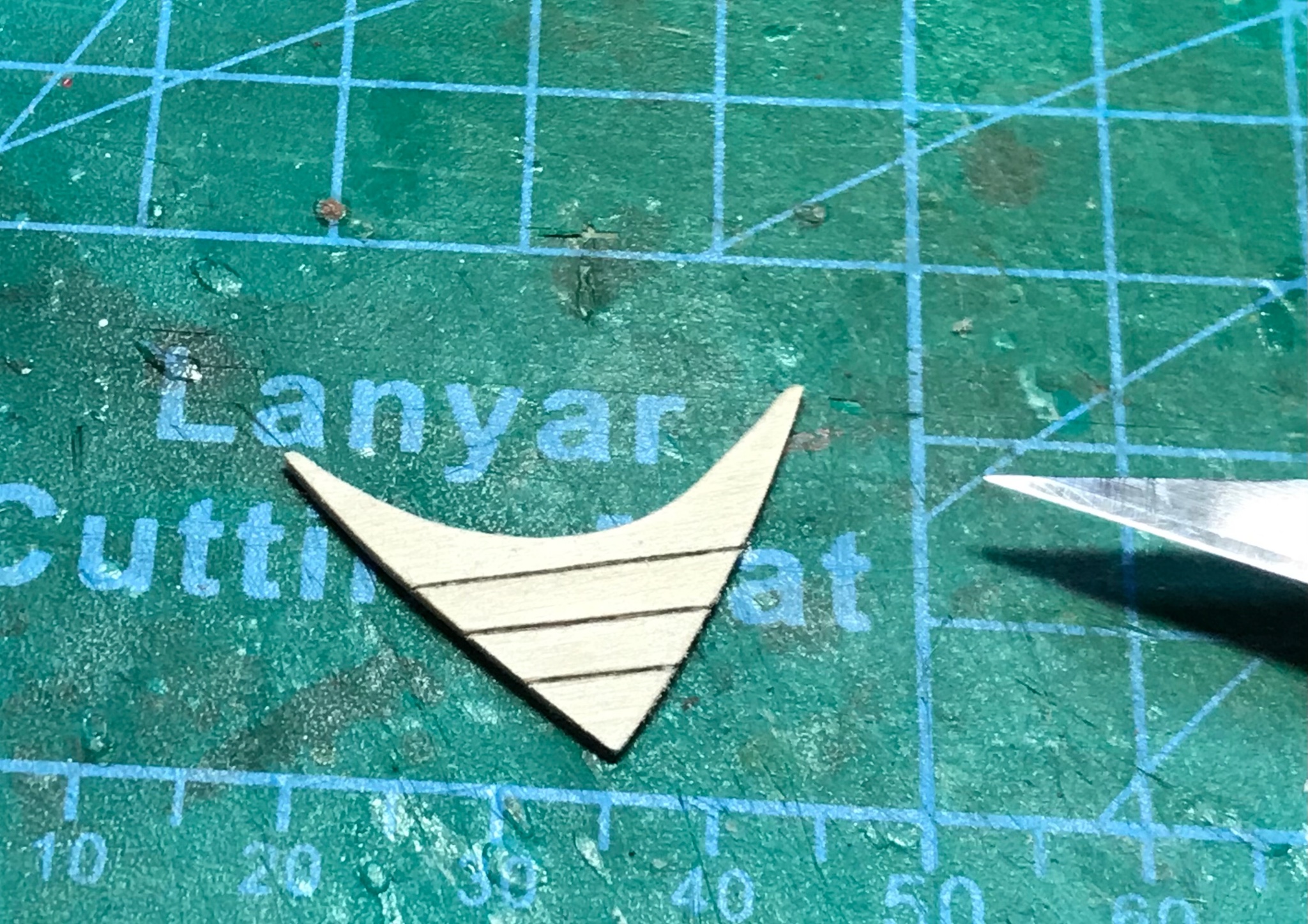
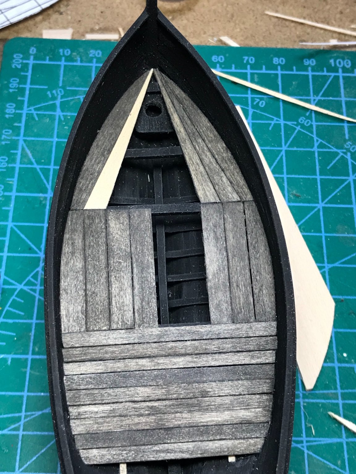
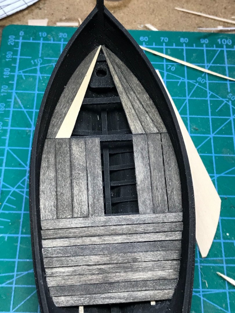
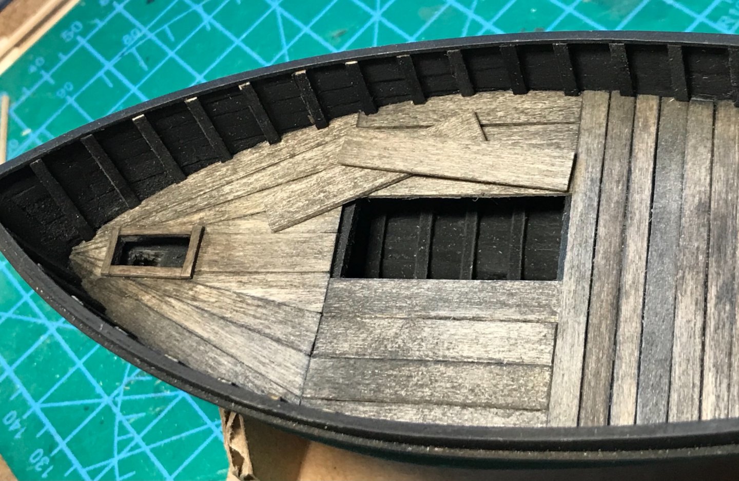
 Continuing to build-up the deck details. It appears all these boats had a rear compartment (cubby), with an access hatch. I decided to scribe planks on 1/32-inch basswood sheet for the wall and roof of the cubby. The scribed lines were "enhanced" with a lead pencil for definition prior to staining. The hatch trim was cut from pear wood veneer. All the finished pieces were then given a wash of diluted India ink for weathering effects. At this point, the rail cap was widened with a strip of 1/32-inch basswood to fully cover the tops of the false frames. The short fore deck was made like the cubby. Here it is before staining. The scribed lines are enhanced with a highly sharpened #2 lead pencil...

- 58 replies
-
- 10
-

-
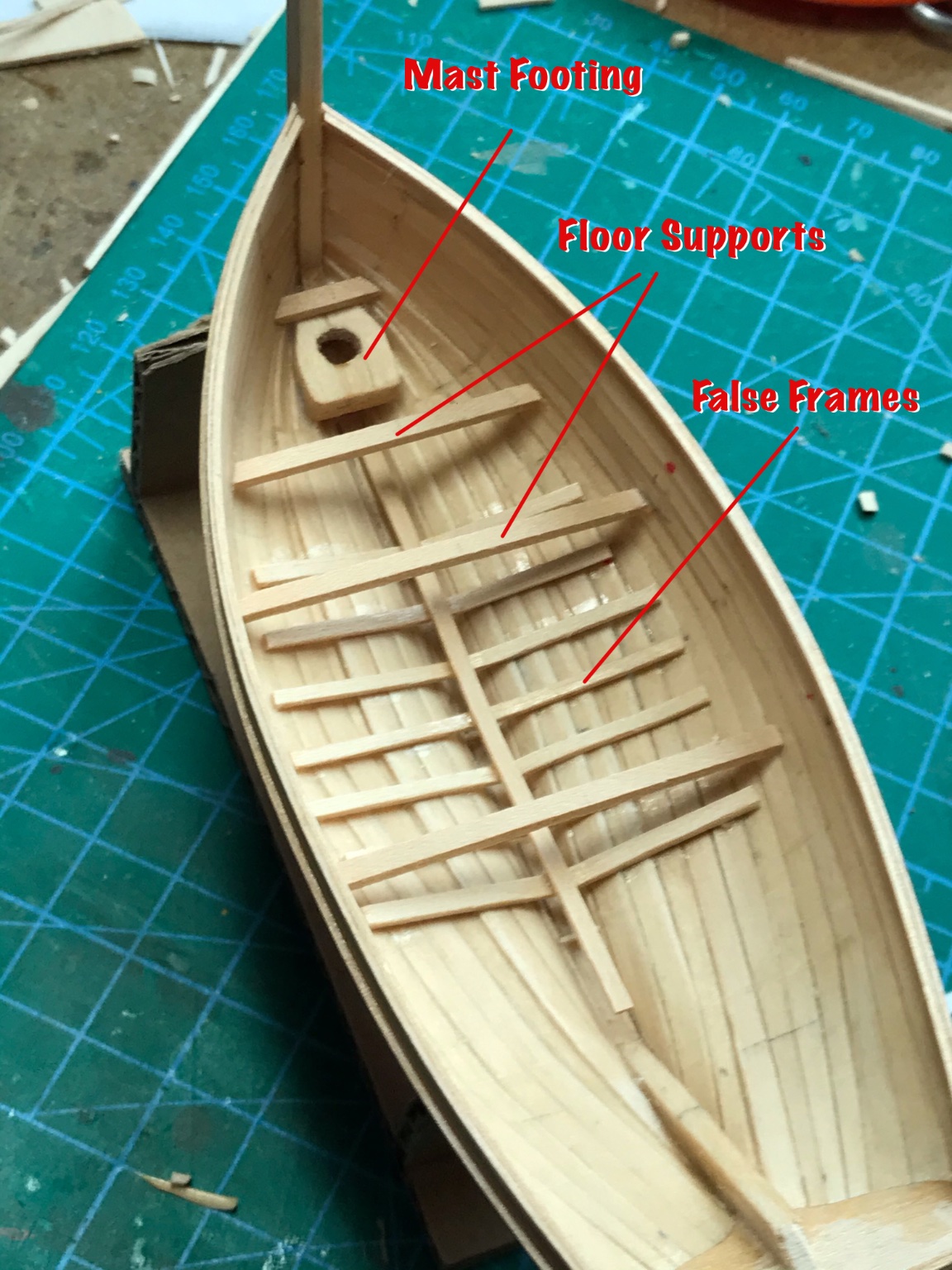
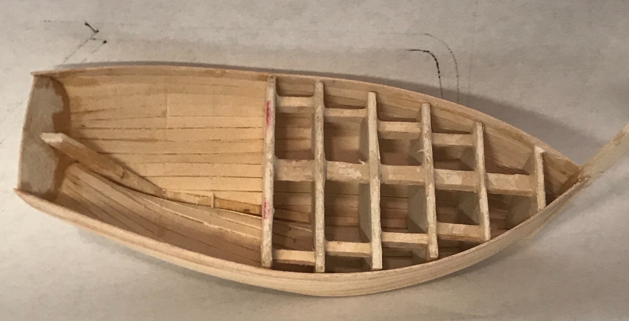
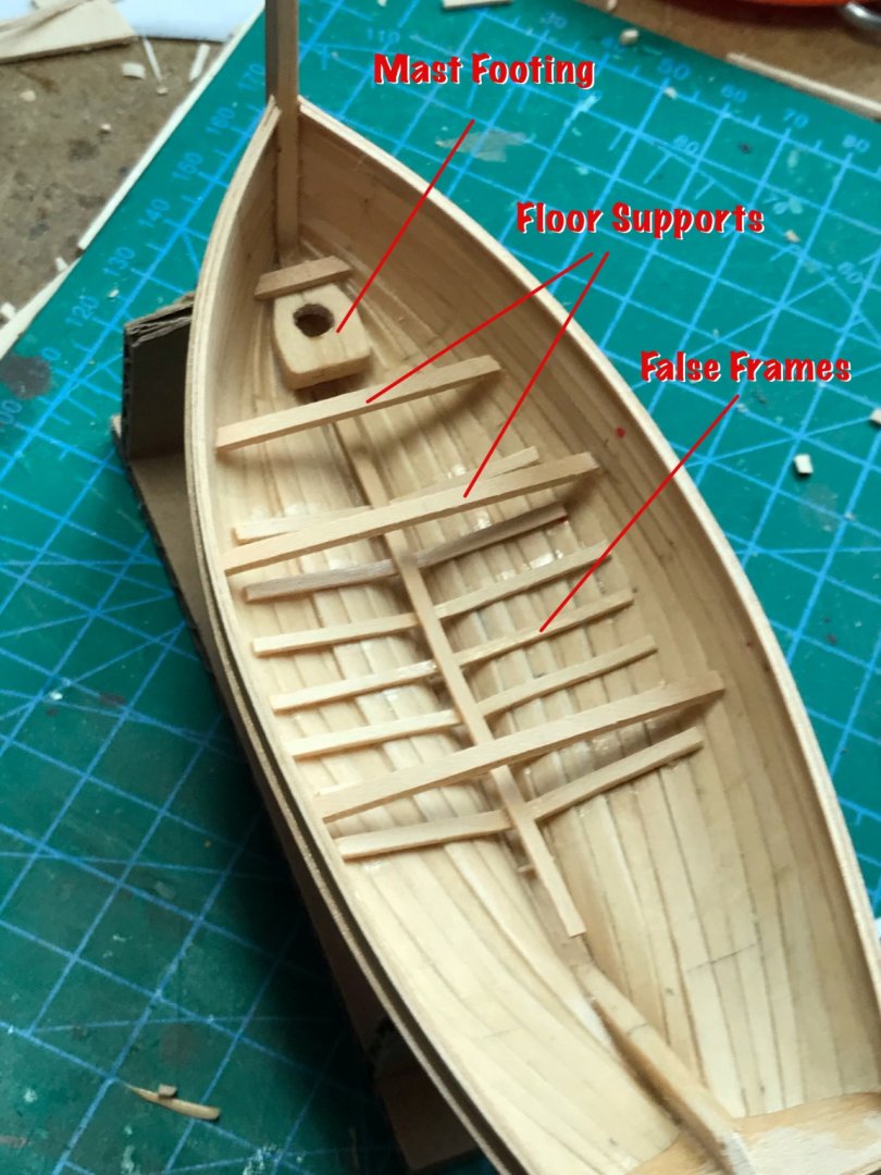
I decided to install individual floor planks. It appears that the floors on these boats were typically divided into three sections: fore, aft, and midships. I found the planks in the midship section always placed in the "fore & aft" direction (parallel to the keel). It looks like the planking in the aft section was either placed "fore & aft" or "athwartships" (perpendicular to the keel). I choose athwartships because it gives more visual diversity in this tiny boat. The planking in the fore section always appears to have been set at angles. Interesting, but challenging to build, as shown here. The floor planks are cut from 1/32-inch sheets of basswood. They are stained with India ink that has been diluted with water and isopropyl alcohol to give a "weathered wood" appearance. Although I think the masts were usually stepped and wedged, it appears these boats also had a short scuttle behind the mast to assist in lowering or removing it. I plan to keep two planks loose for display purposes. Also, the process of adding false frames has begun. These are strips of basswood, painted black prior to installation...
-
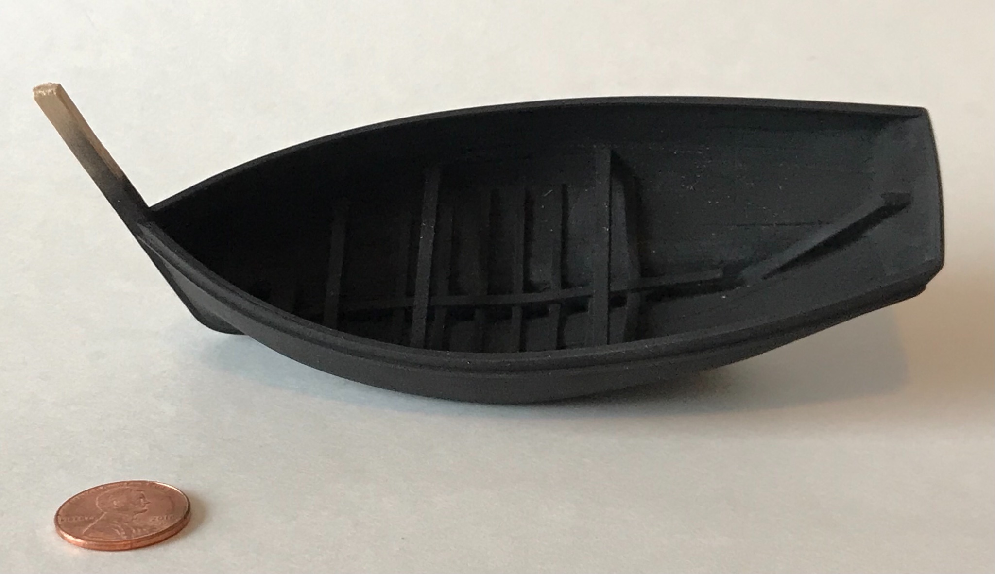
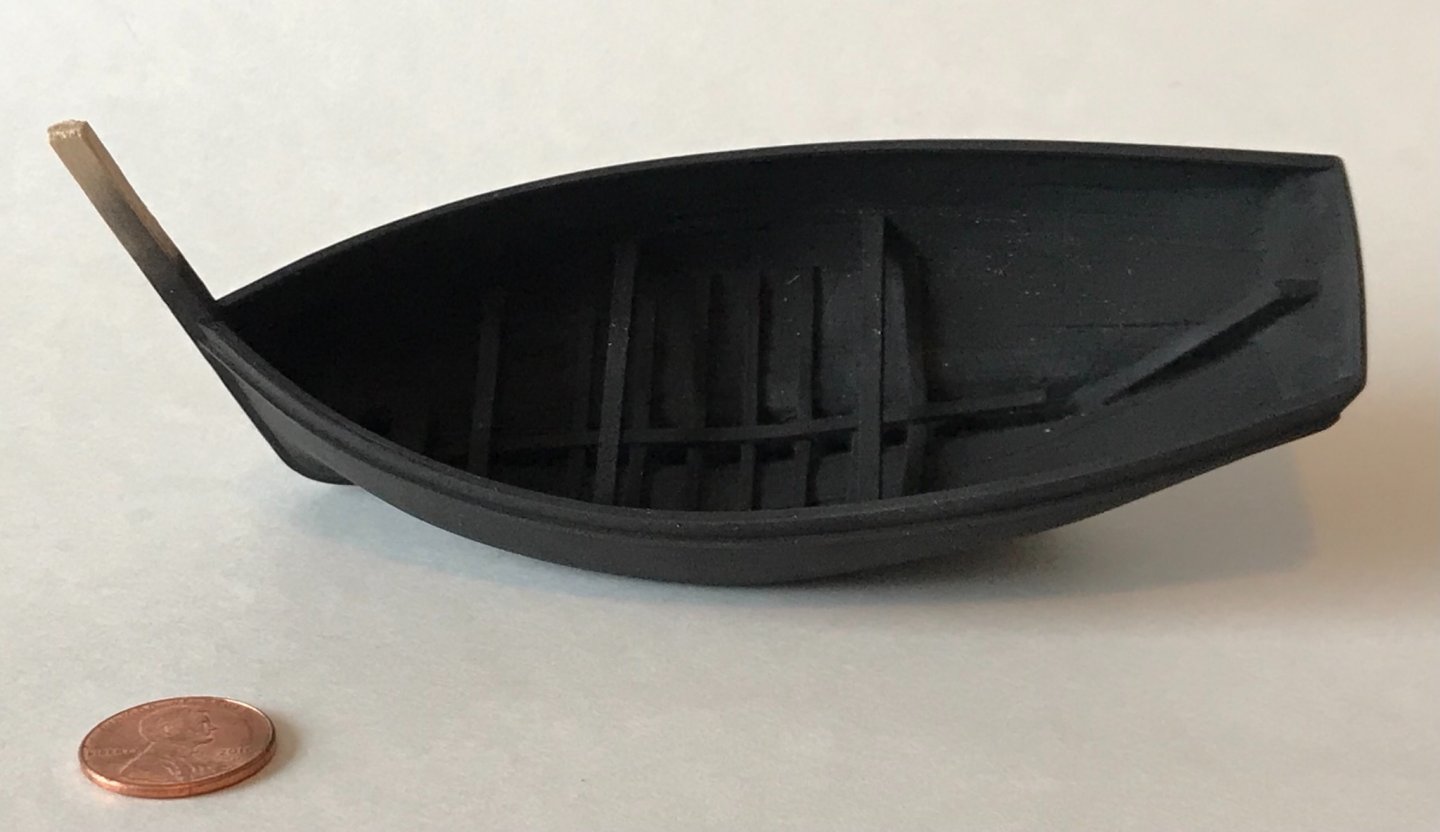
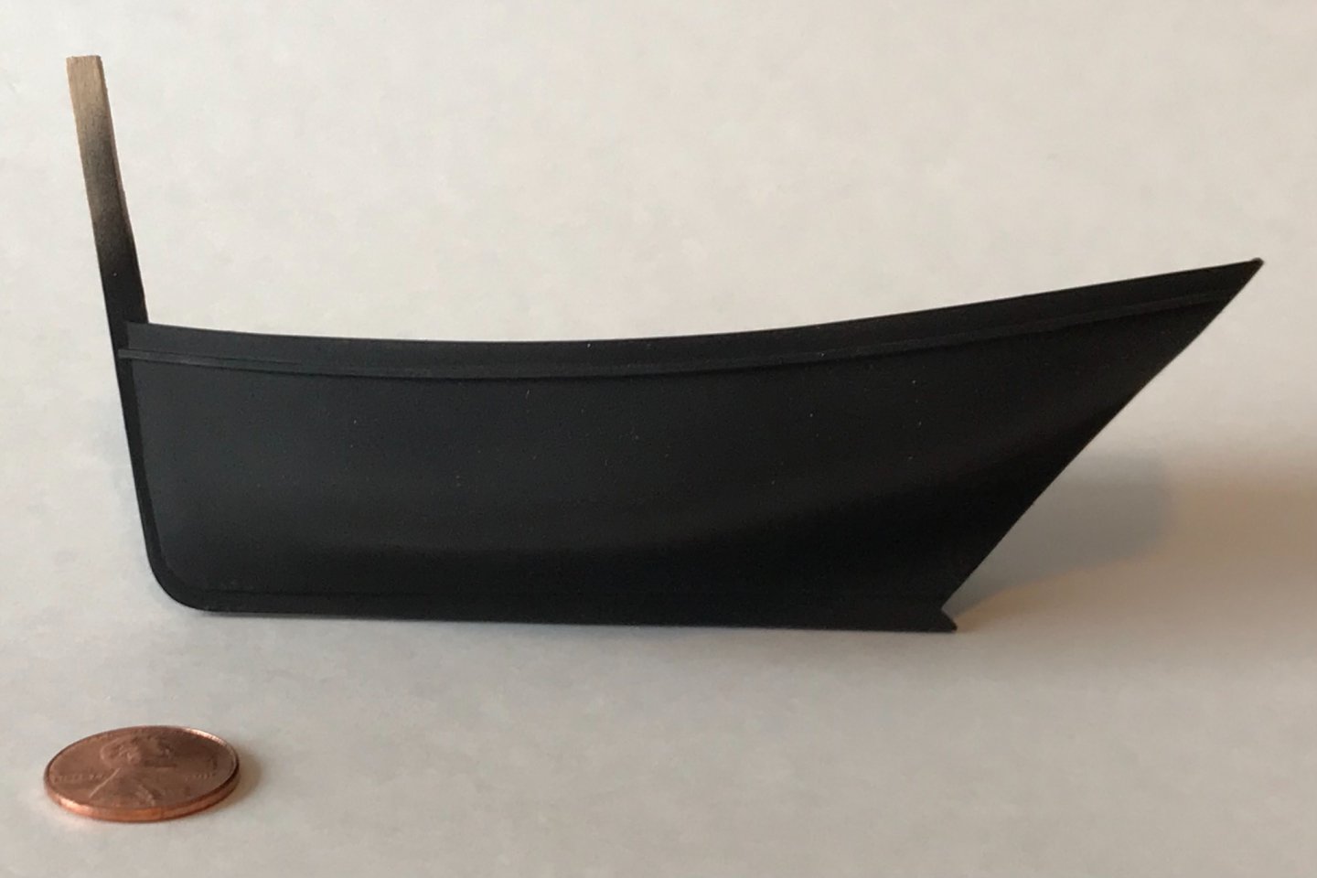
The hulls of these boats were tarred, giving them their blackish color. At this point, it seems necessary to paint the hull black before going any further with construction. If I wait, painting will be much more difficult because of the other bits and pieces that I plan to add, especially the floor planks. I fully expect that touch-up painting will be needed later, as constructions progresses, and to fix any spots that get worn by handling. I applied Testors' flat black lacquer with an airbrush.
- 58 replies
-
- 10
-
-
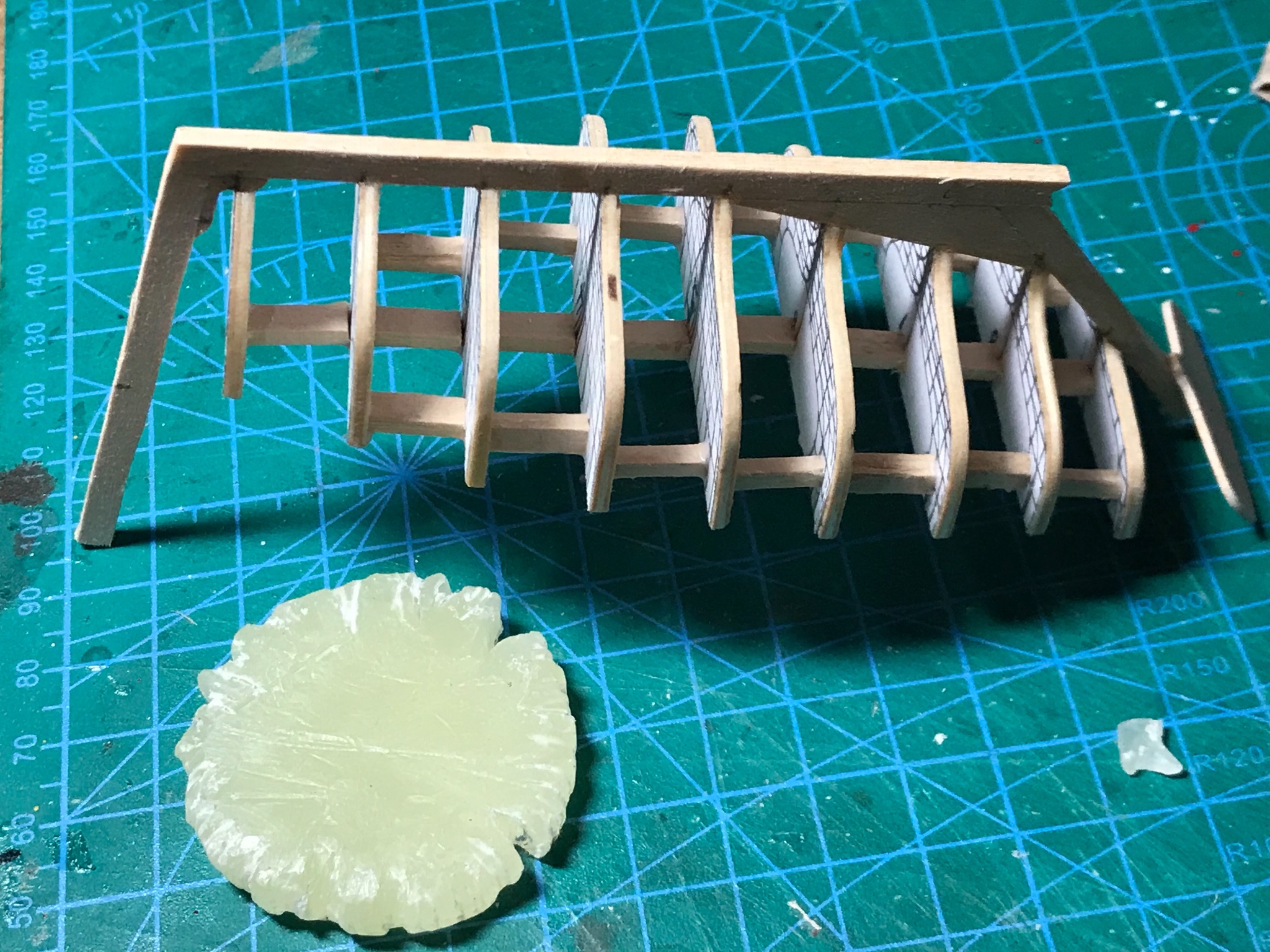
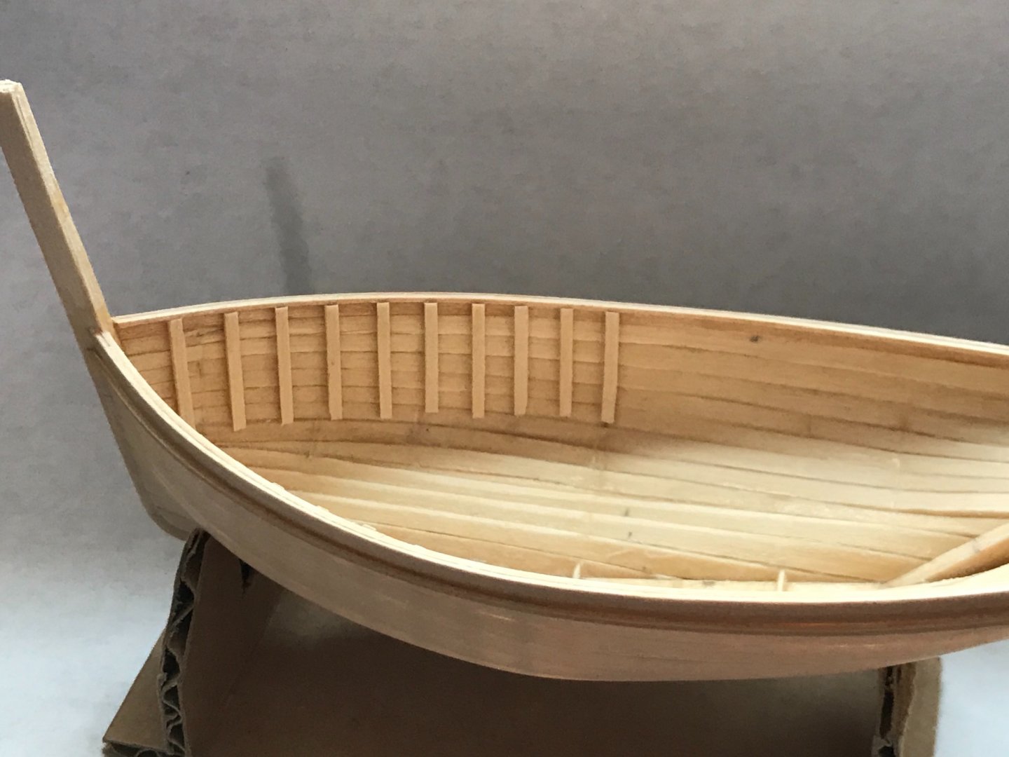
I started adding false frames, but decided to stop. These boats had floors and it seems it would be easier to install frames after the floor is in. Luckily, a little water softened the PVA glue and I was able to remove the half day's work and start anew...🤨 These frames were all removed... Next, I decided to provide some visual interest under the floor by leaving some floor planks off, later. It appears that some or all the floor planks on these boats were removable (especially amidships). So, the area that would be partly visible needed lower false frames. I also installed supports for the floor boards.
-
Thanks Wintergreen. I'm slowly improving...
-
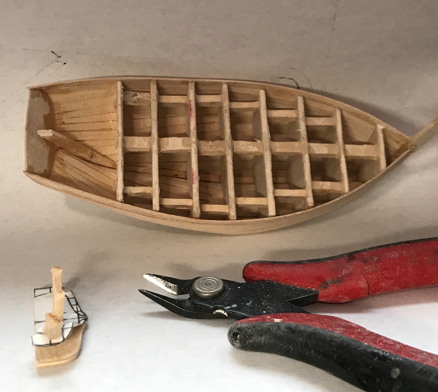
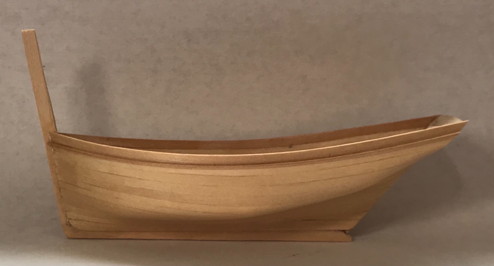
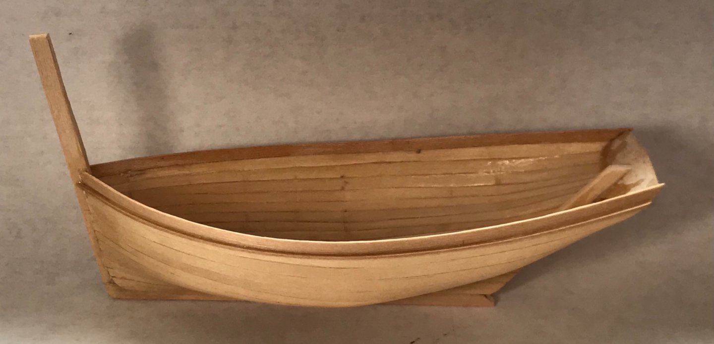
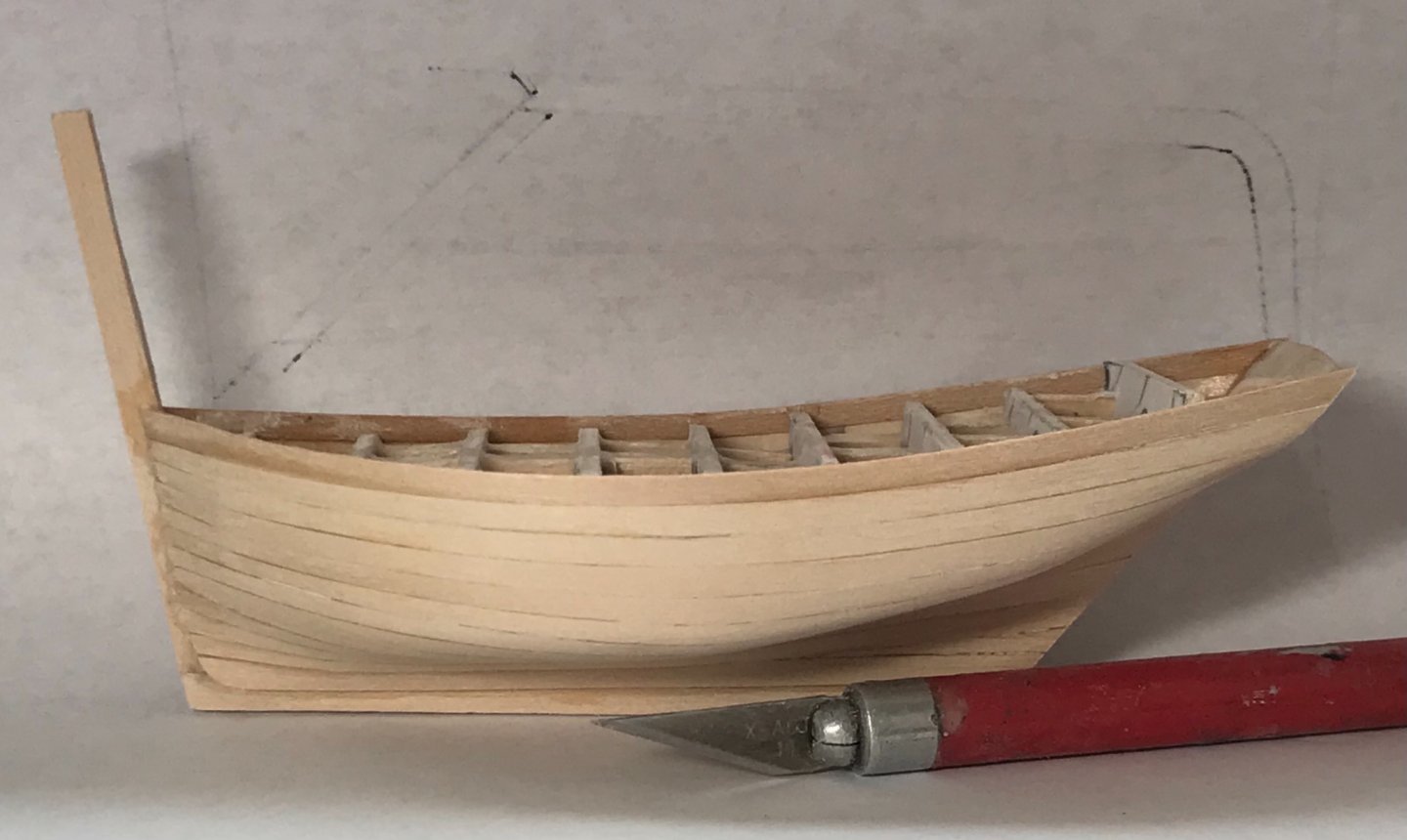
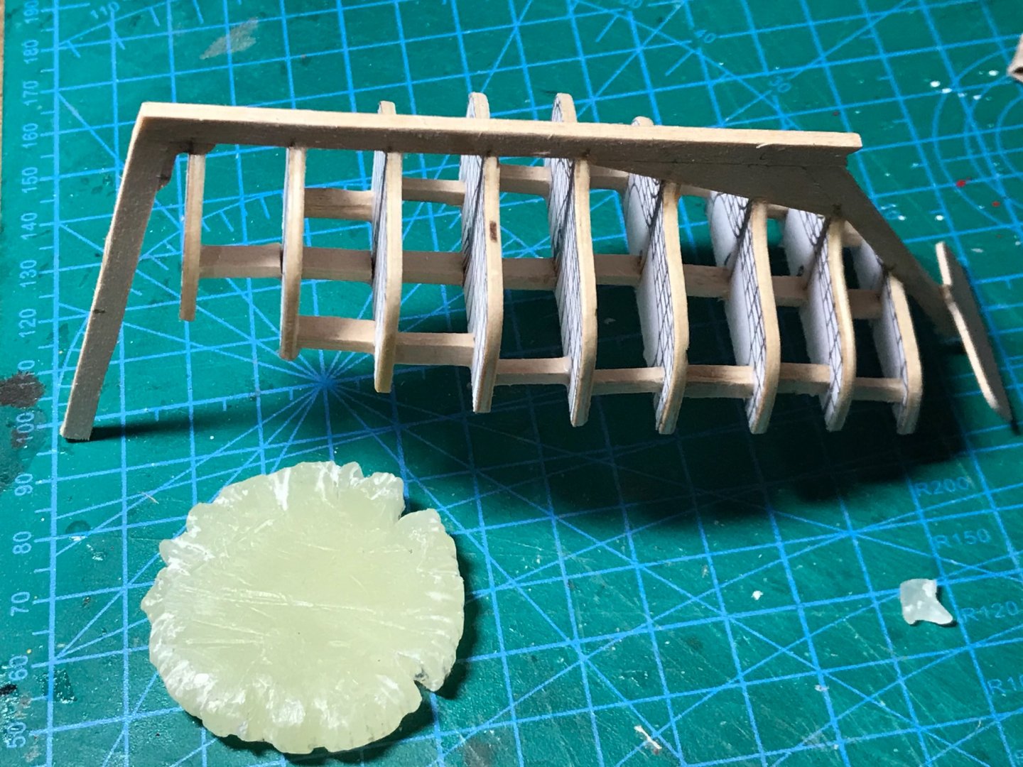
Removing the bulkheads always raises a little angst. This is the third open boat I have tried in this manner, and they have all worked well. Even so, it seems like there could be a high likelihood for damage or total failure when removing the bulkheads. The CA glue does grab the bulkheads, even with all the wax preparation. However, a little gentle rocking and twisting, and things have always come out ok. It's a mystery... I started by cutting the braces on the first bulkhead, removing it with a little twisting and turning, and then moving on to the next in the same manner. Here, the first bulkhead has been removed... Progress continues. Notice the indentations on the interior of the planks. This was caused by applying the planks "wet." They were soaked in water to make them more pliable during application. Some of the dents will sand out. The rest will be covered by "false" frames, which I shall apply later... Here, a trim piece has been fitted under the upper strake on the outside of the hull... The hull is ready for detailing!


- 58 replies
-
- 12
-
-
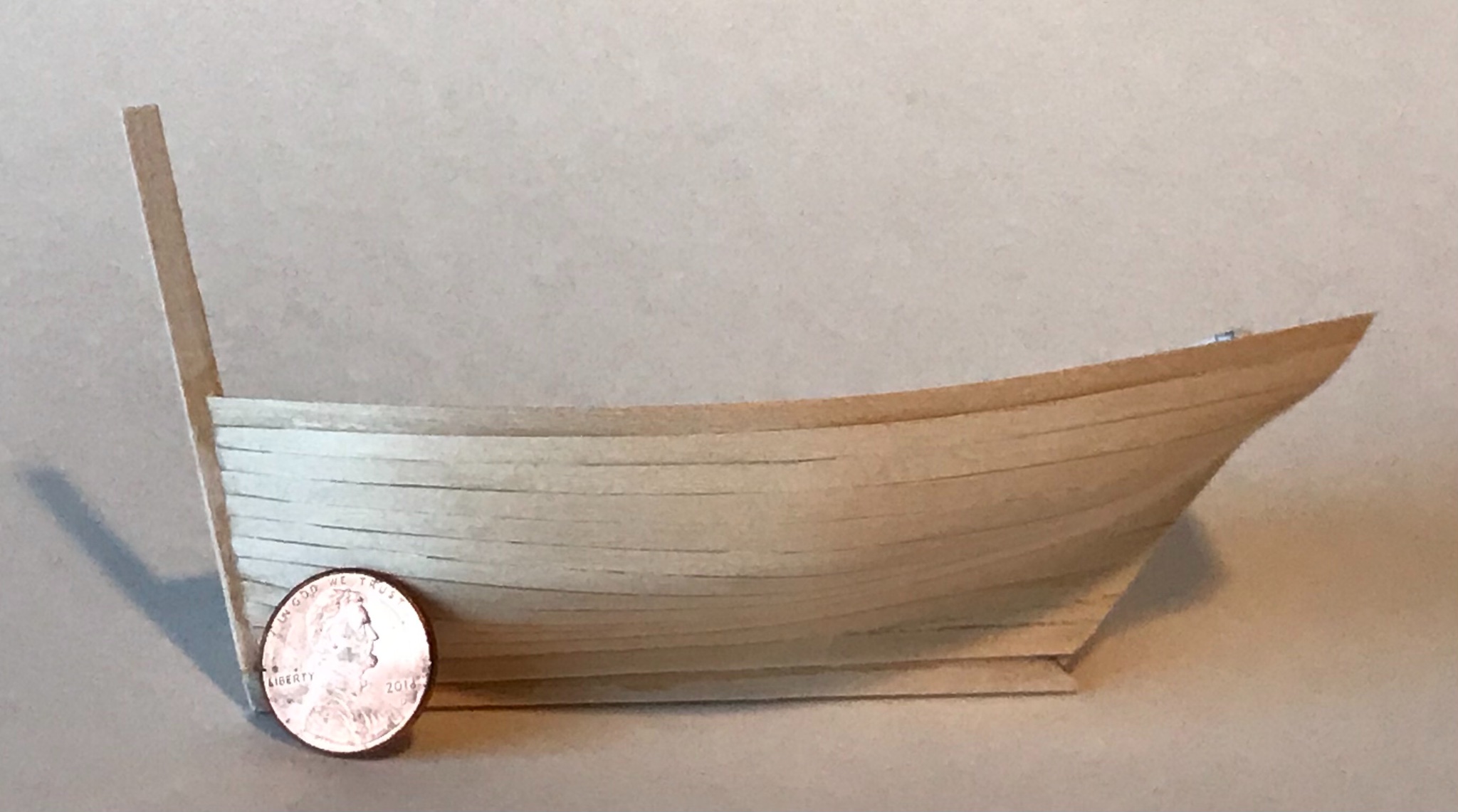
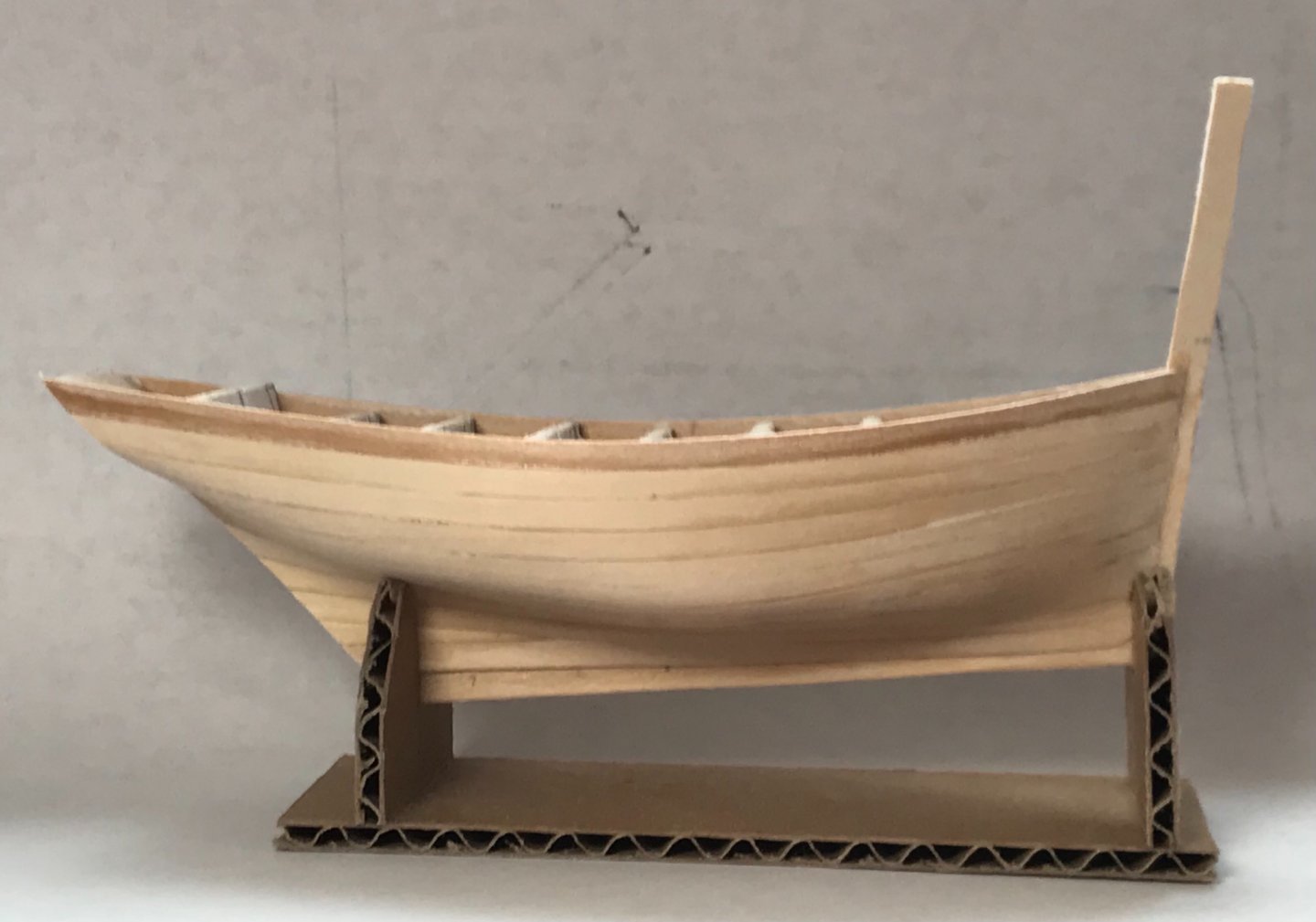
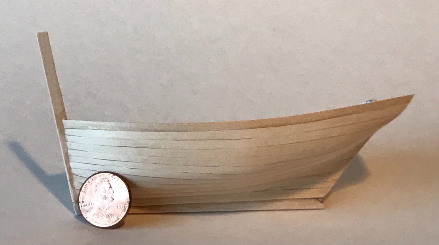
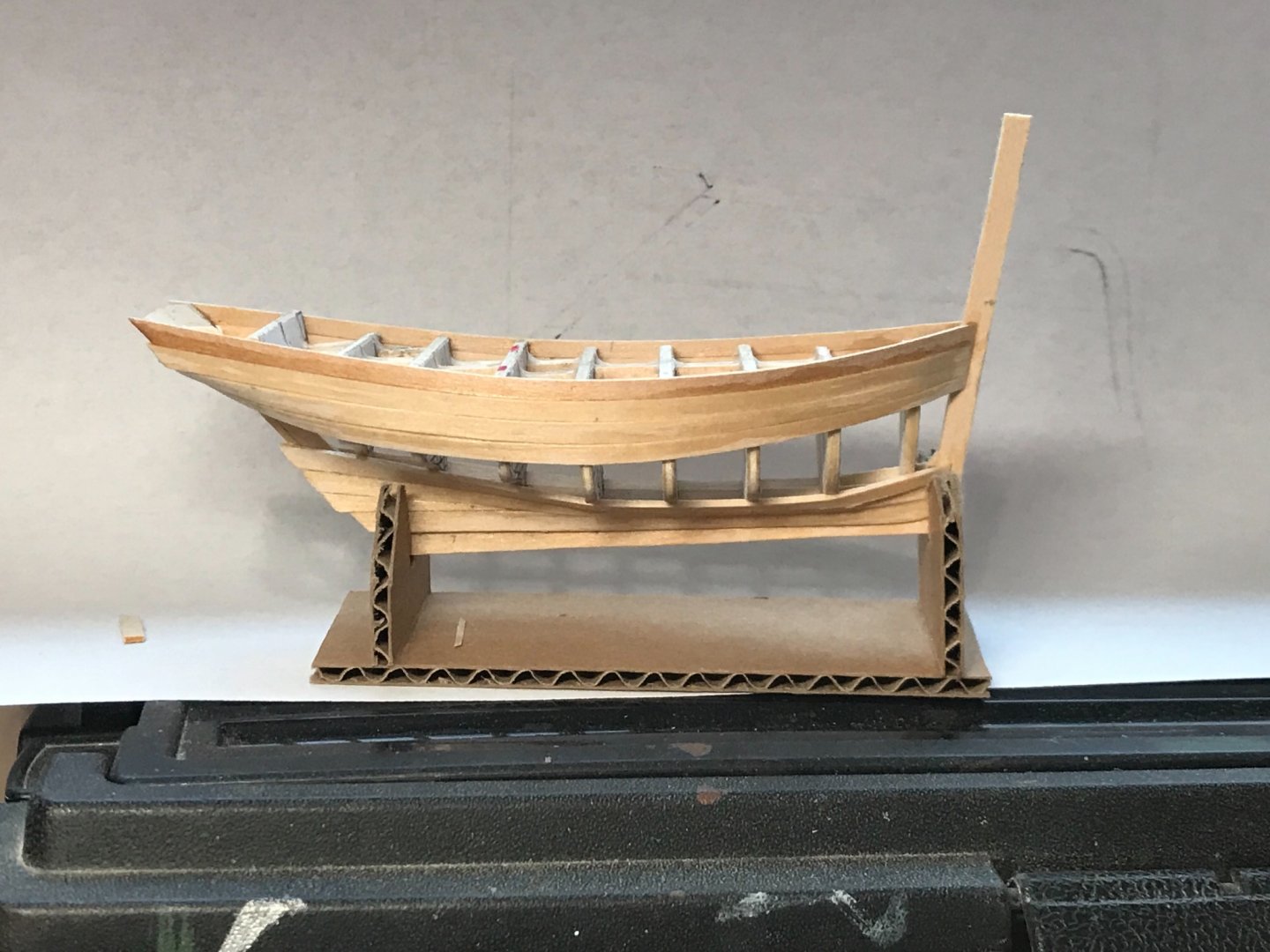
Planking is done....whew. Planking always takes longer than I expect, and I'm not very good at it. Thankfully, this little boat needs little planking😃. I used 1/32-inch basswood sheet cut in 3mm strips and tapered as needed. Combining the modified bulkheads from one set of plans with the keel/stern/stempost of another seems to have worked (better to be lucky, than good). In the photos, you will notice a really long stempost. That will be cut down when I decide I no longer need a handle on the model... After sanding. Sanding was done with the bulkheads still inside. This provides support from the violence done during sanding...
- 58 replies
-
- 14
-
-
Planking started with the garboard and top strakes. CA (cyanoacrylate) glue is used. The garboard is shaped and glued to the stempost, sternpost, and all along the keel. The top strake is only glued to the transom and stem posts, but it is snug against the bulkheads, even though it is not attached to them. Later, the top plank was tacked (with a little CA) to the bulkhead with the red marks. This was to keep everything from sliding up and down, as more planks are added. Planking continues from top down, and bottom up. Planks are glued to each other, but not to the bulkheads (at least not on purpose... a little glue always finds its way to where it is not wanted). This will take a couple of days...
-
Welcome aboard!
-
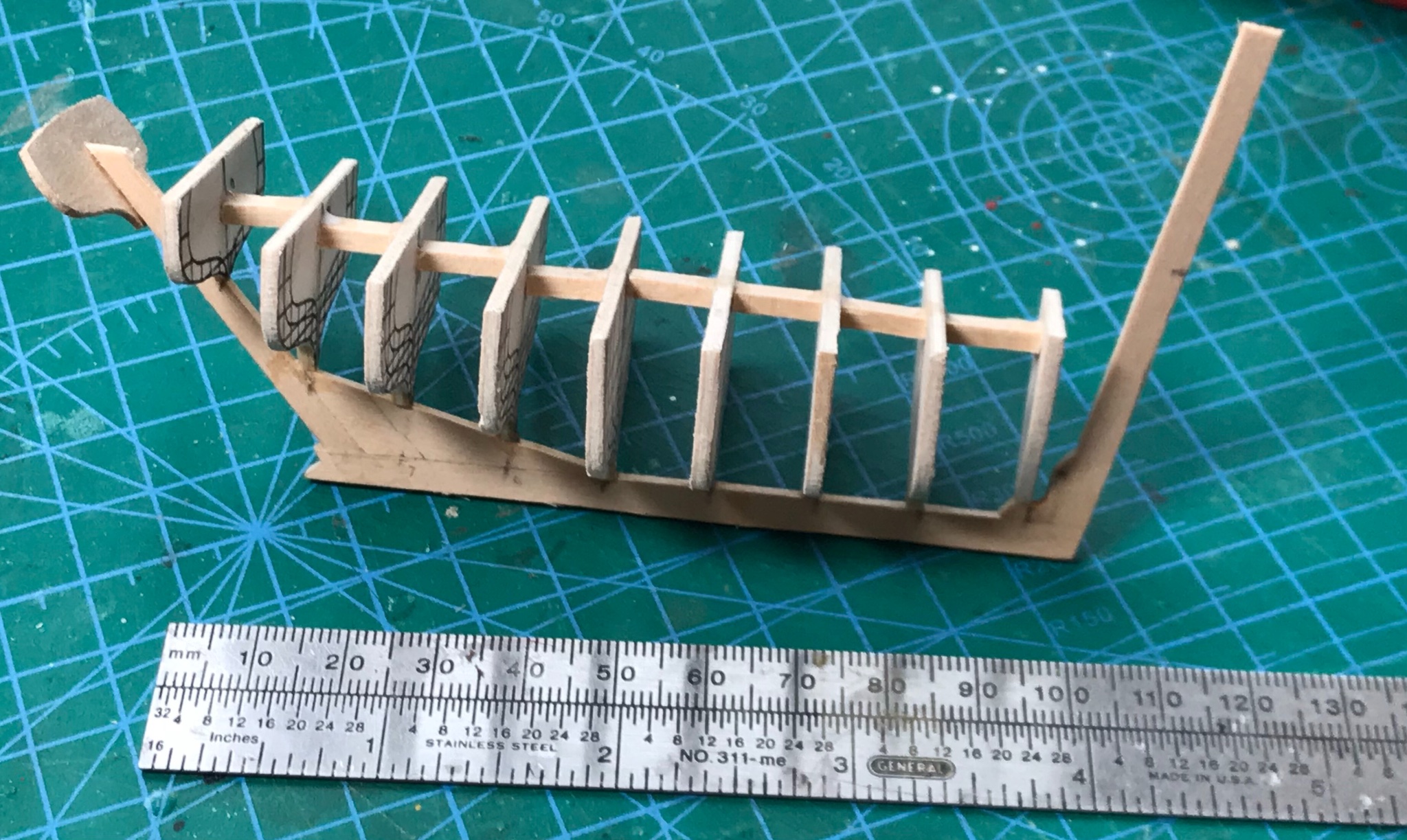
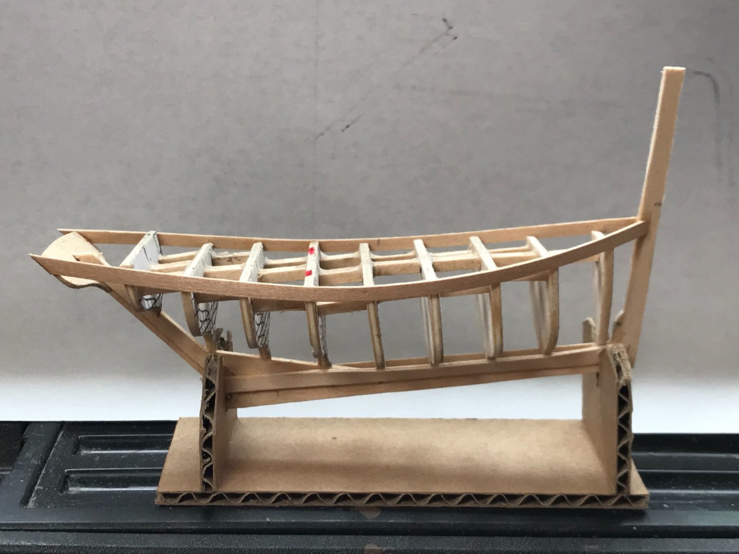
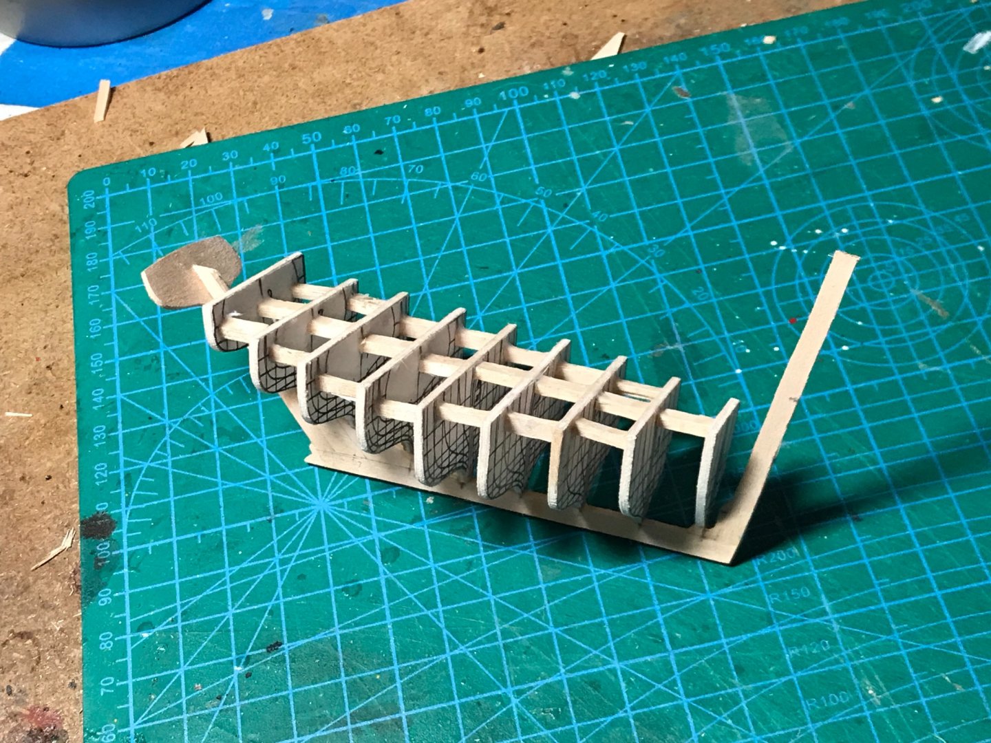
I mentioned earlier that the keel is from a profile drawing of one boat and the bulkheads are from line-plans of a similar boat with a different profile (different angle on the keel, sternpost, and stempost). This occurred because the profile drawing looked more like the boats in historical photos. I had to guess-timate how the two elements might go together. The bulkheads were also stretched in width (with a little computer magic) to maintain the width to length ratio (about 40%) exhibited by these boats. I like to think all this mixing, guessing, and "eye-balling" during the hull construction recalls how most of these boats were built in real life. I've read that they were generally built by one person, with no plans, but lots of ideas of how things were done in the past... The Misainier is an open boat, so the bulkheads I use to shape the hull are only temporary, and will be removed later. After checking for fit and how the sheer may look, the bulkheads were glued to the keel with CA glue at one small point. They were "squared-up" to the keel and each other by "eyeball" as the glue quickly set. Then, cross-braces were installed down the center of the boat, between the bulkheads (but not to the stempost or transom), with white PA glue. This provides much needed support to the bulkheads, which are just hanging on to the keel at one small point. More braces were installed to give added strength, and ensure everything stayed in alignment... Once everything was dry and solid, I rubbed wax into the edges of the bulkheads. When planking begins, I want the planks to be glued to each other, but I don't want them to stick to the bulkheads. The wax was "melted in" with a quick blast of heat from a hair dryer...

- 58 replies
-
- 11
-
-
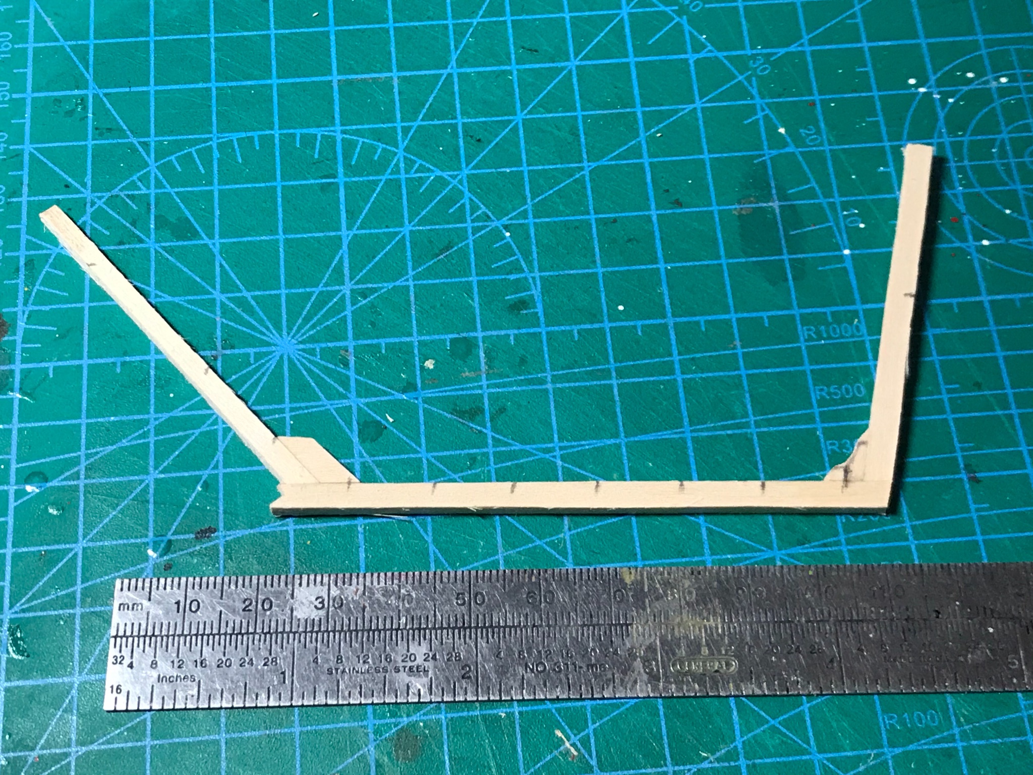
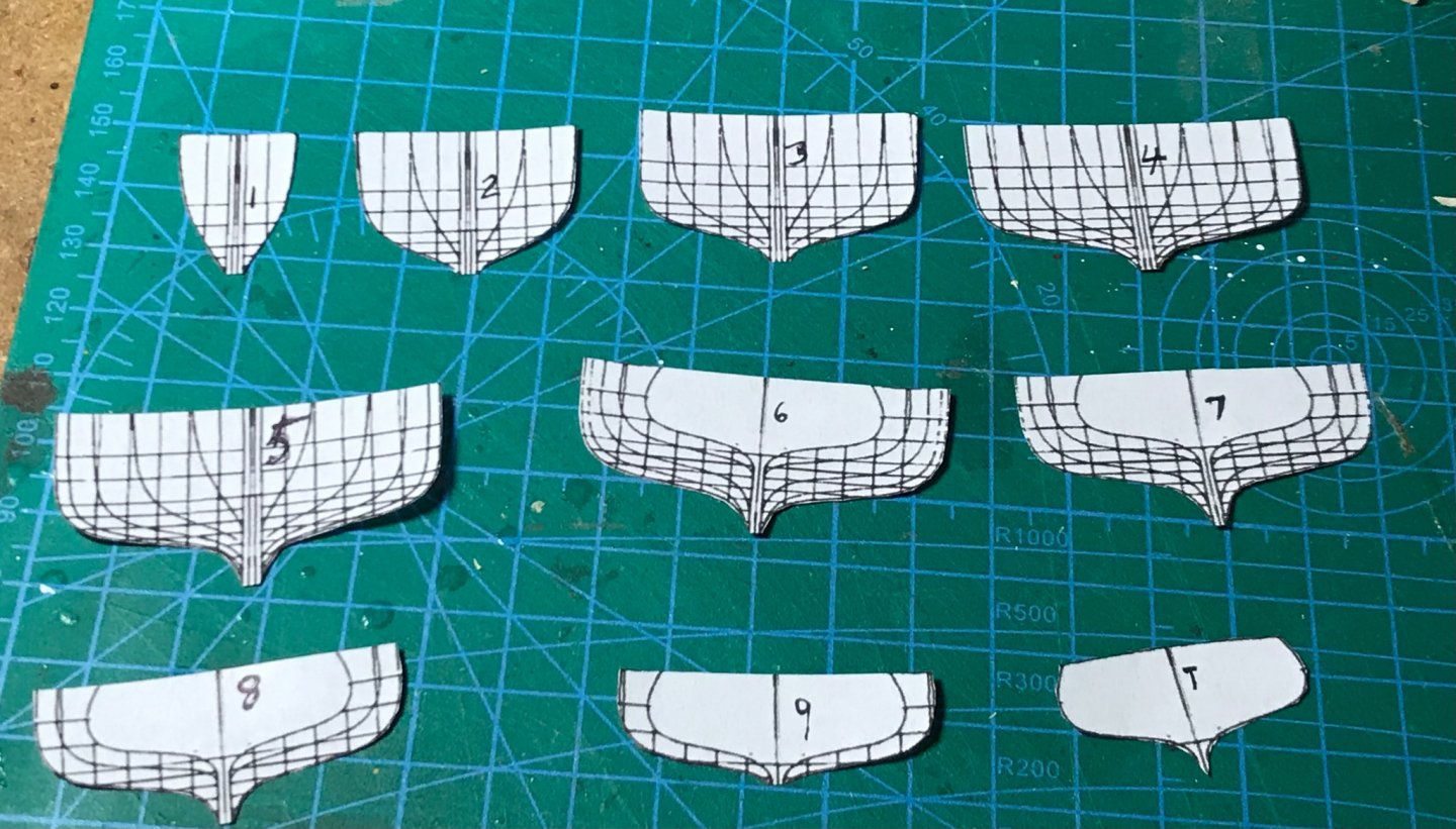
I wanted to build a small and simple model that could be completed in a short time period, but I also wanted something historically significant and interesting with lots of information available. The Misainier filled the bill! The 6-meter boat I have planned will only be 5 inches (127mm) long. Life starts with a basswood keel, stempost and sternpost based on a drawing I found on the internet. I developed cross-sectional plans for the bulkheads from a different internet find. Anxious to see if mixing components from completely different sources will work. Some modification was necessary by widening the bulkheads, without changing their height. Their location along the keel was altered to fit the angle of the keel in relation to the stem and sternpost... Bulkhead and transom templates...

-
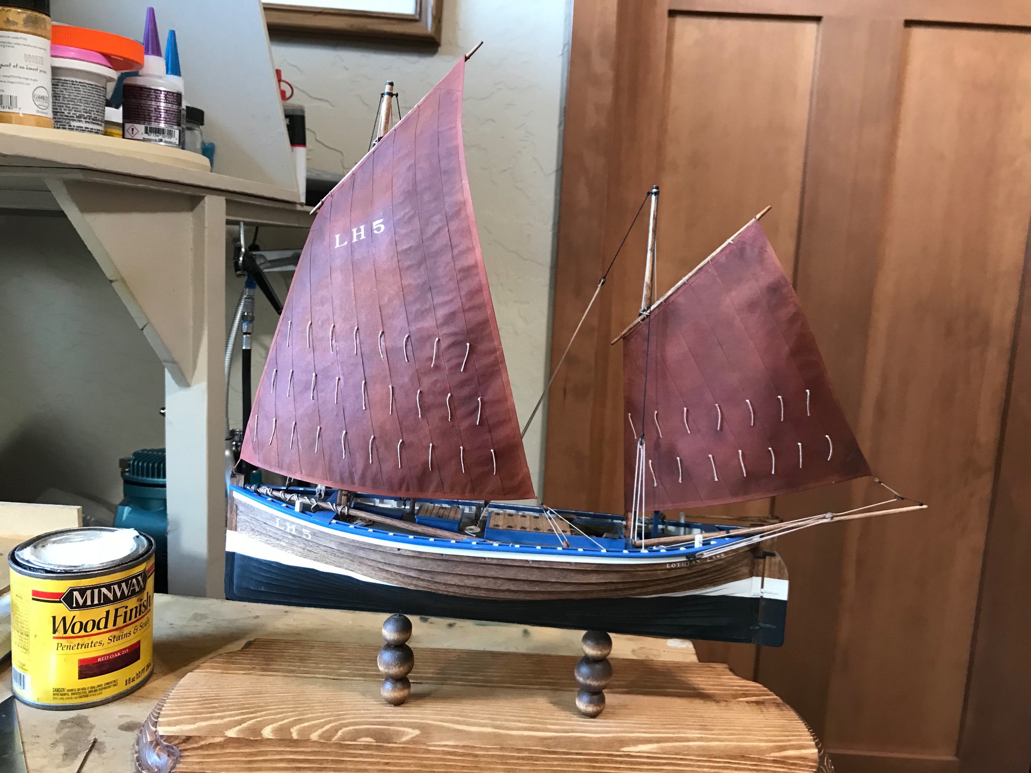
This will be a 1/48 scale model of a six meter (20 foot) Misainier fishing boat from the early 1900s. The Misainier was an important feature of the French Atlantic Coast in the early part of the 20th century. These little boats were usually 4 to 8 meters long, single masted, lug rigged, and built by individuals without formal plans. Hundreds plied the coastal fishing grounds of Brittany until the mid 1900s.
-
Thanks Wintergreen! Don't know what's next. Waiting for inspiration...
-
I didn't see any direct quotes, but one of my books said a Fifie beat a steamer back to port. The steamer was doing 14 knots!
-
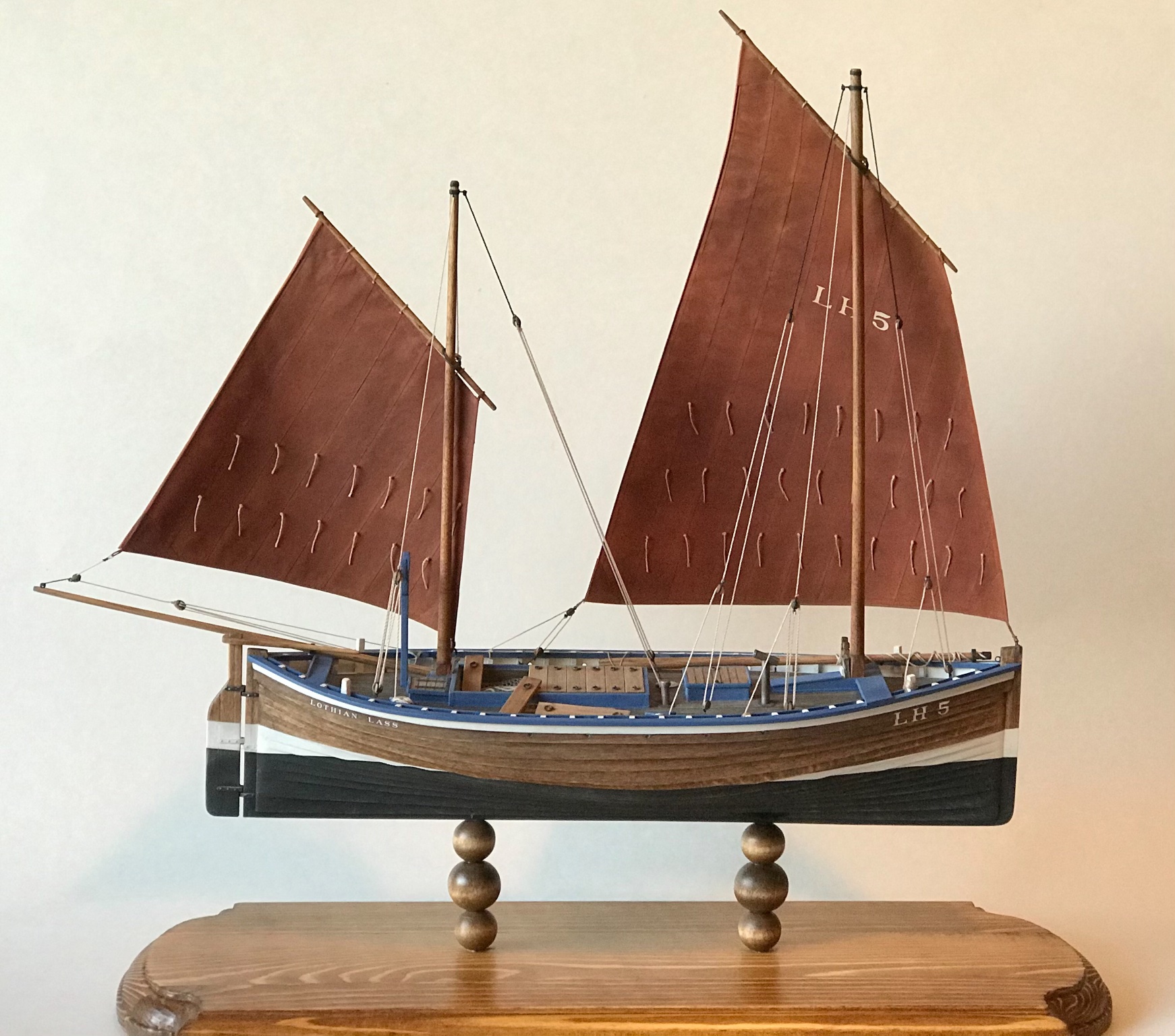
All done! A gallery of finished images is at: https://modelshipworld.com/gallery/album/2267-1870-scottish-fifie-by-gbmodeler/

- 86 replies
-
- 15
-
-
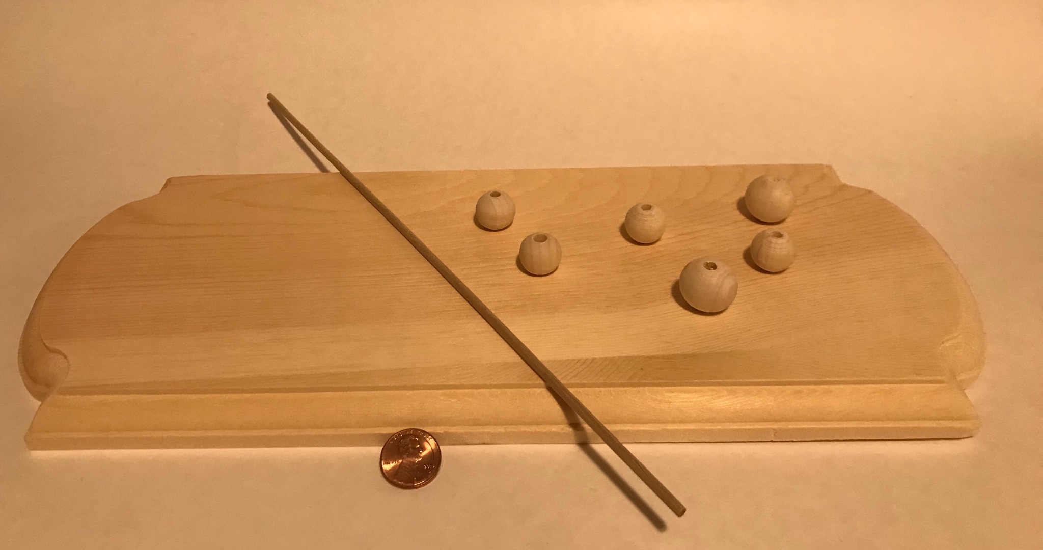
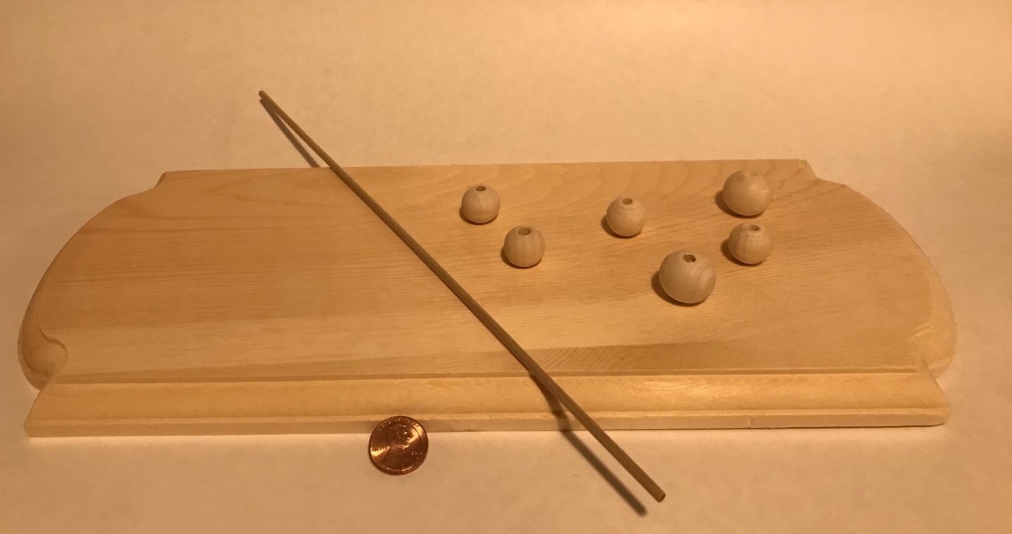
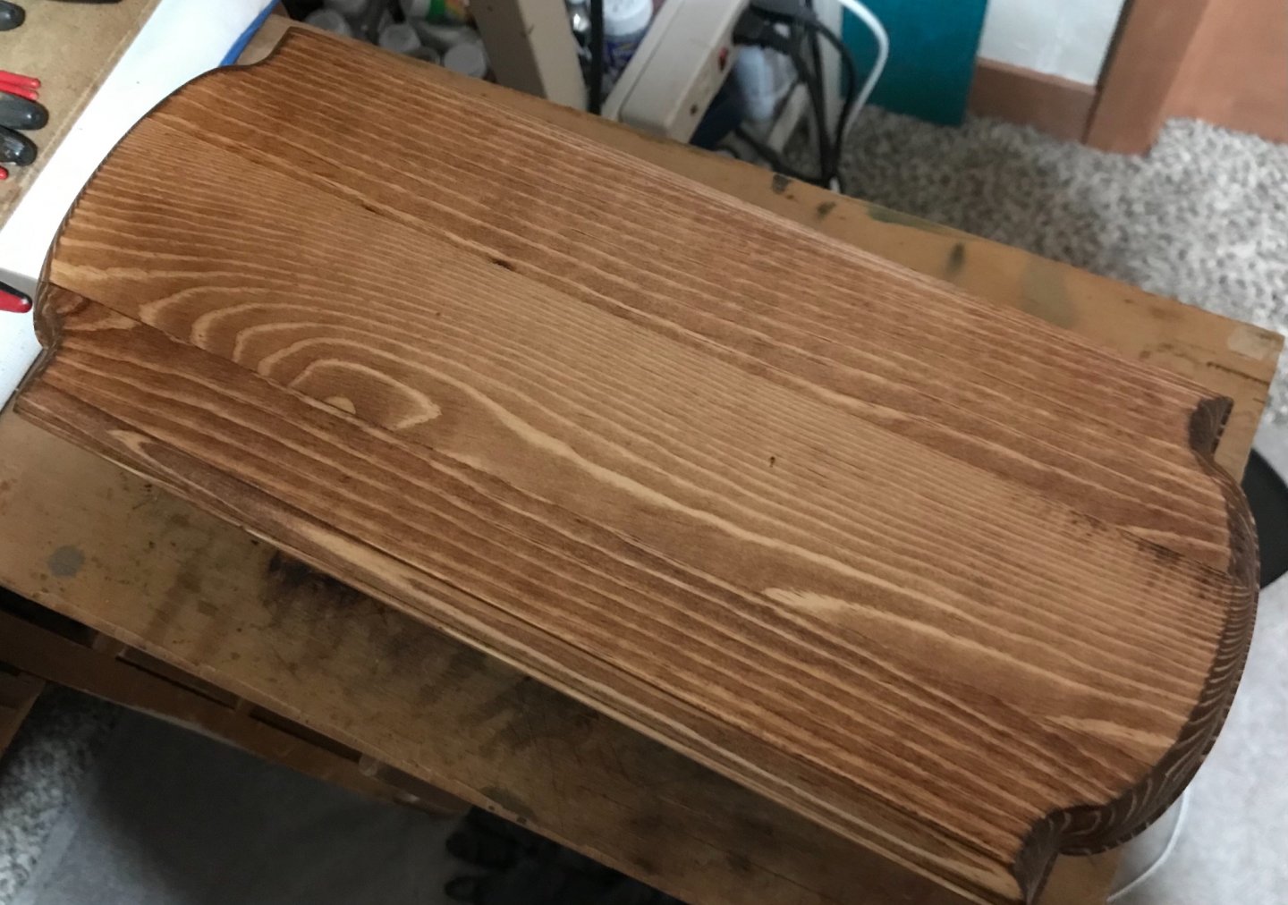
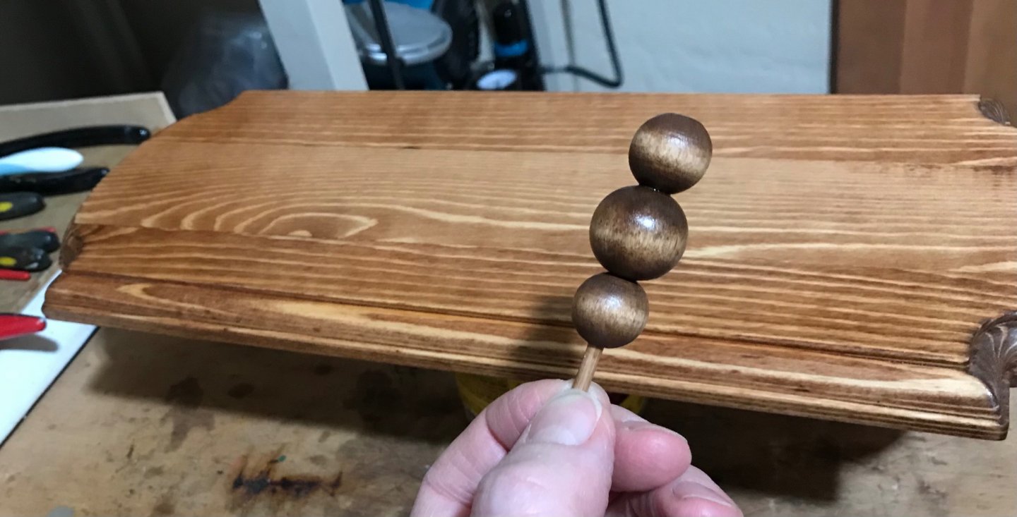
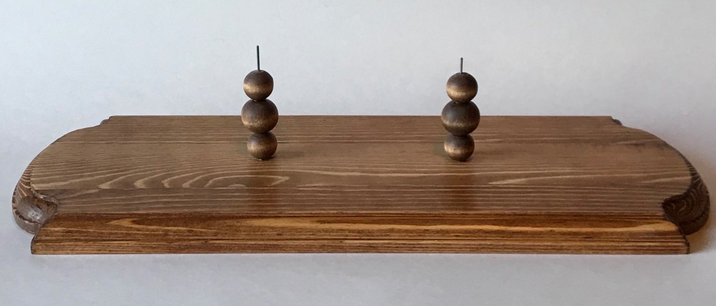
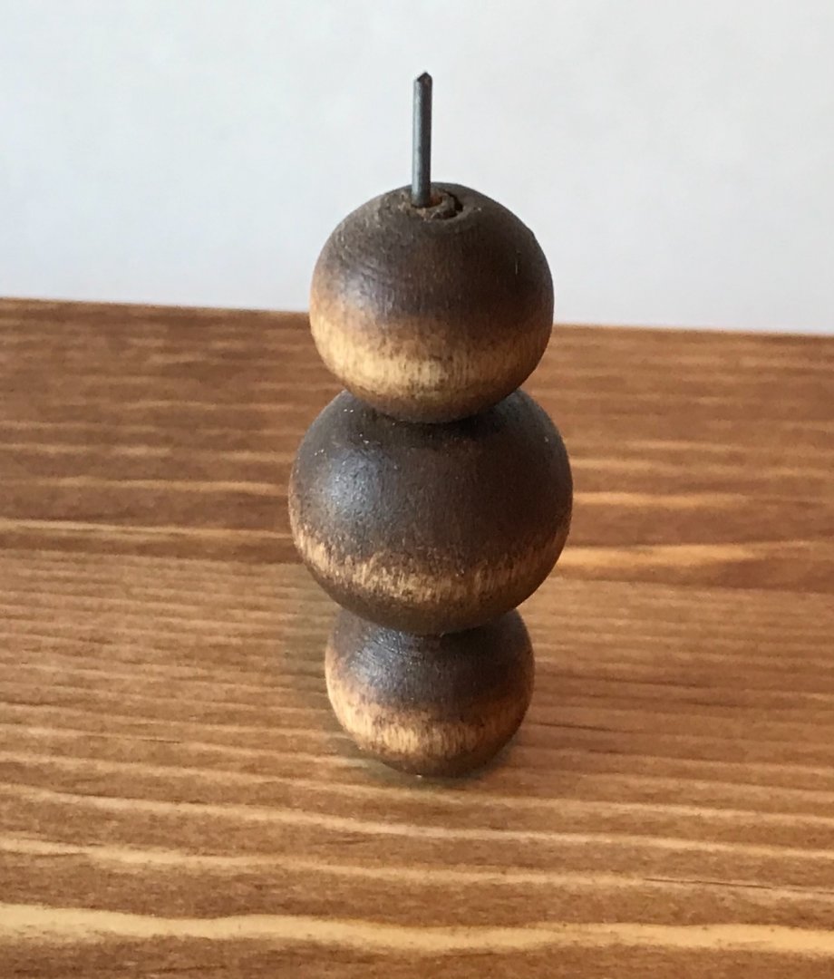
I always make a stand for my boats from inexpensive, unfinished wooden plaques. These are found at craft stores for just a few dollars each. I also like using wood beads for "posts" on the plaques. I say I like using the beads because I purchased a small bag of them (various sizes) and I think I have a life-time supply😬. The last element to my stands are wooden dowels (1/8 inch diameter) and steel piano wire (about 1mm diameter). The plaques are laminated pine and not very high quality. I'm good with that because I think a "work boat" should be displayed simply. I don't want the stand to be higher quality than the model! 🤔 Here are most of the raw materials and a penny for scale... I stain the plaque and beads with an appropriate color, and then coat them with "wipe-on" polyurethane varnish. Usually three coats of varnish does the trick. The polyurethane dries (for handling) in a few hours, so the whole process only takes a couple of days from start to finish... The beads have pre-drilled holes, so I just glue them to the wood dowel... The dowel is cut flush with the top of the pile, and the peg on the bottom is glued into a hole drilled in the plaque. After that, I drill holes down the center of the dowel, almost the full length, and insert the steel piano wire as far as it will go, finished off with some light tapping with a hammer... I drill holes through the keel of the boat to accept the piano wire. After a little adjusting with pliers to make sure the wire is straight ( to make sure the ship is straight) and viola... The ship is mounted!

-
Very cool! You are a botter expert!!! When I build one, I will rely heavily on your web site info!
-
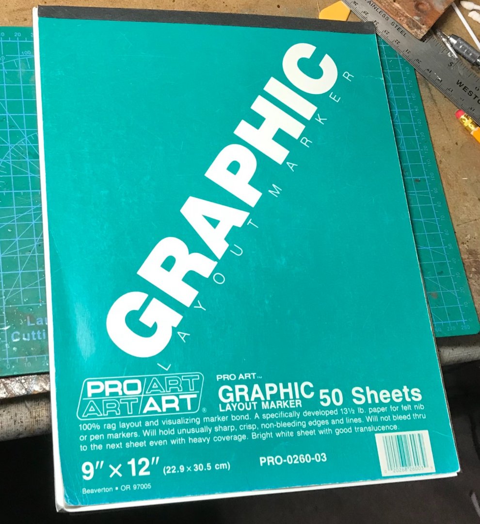
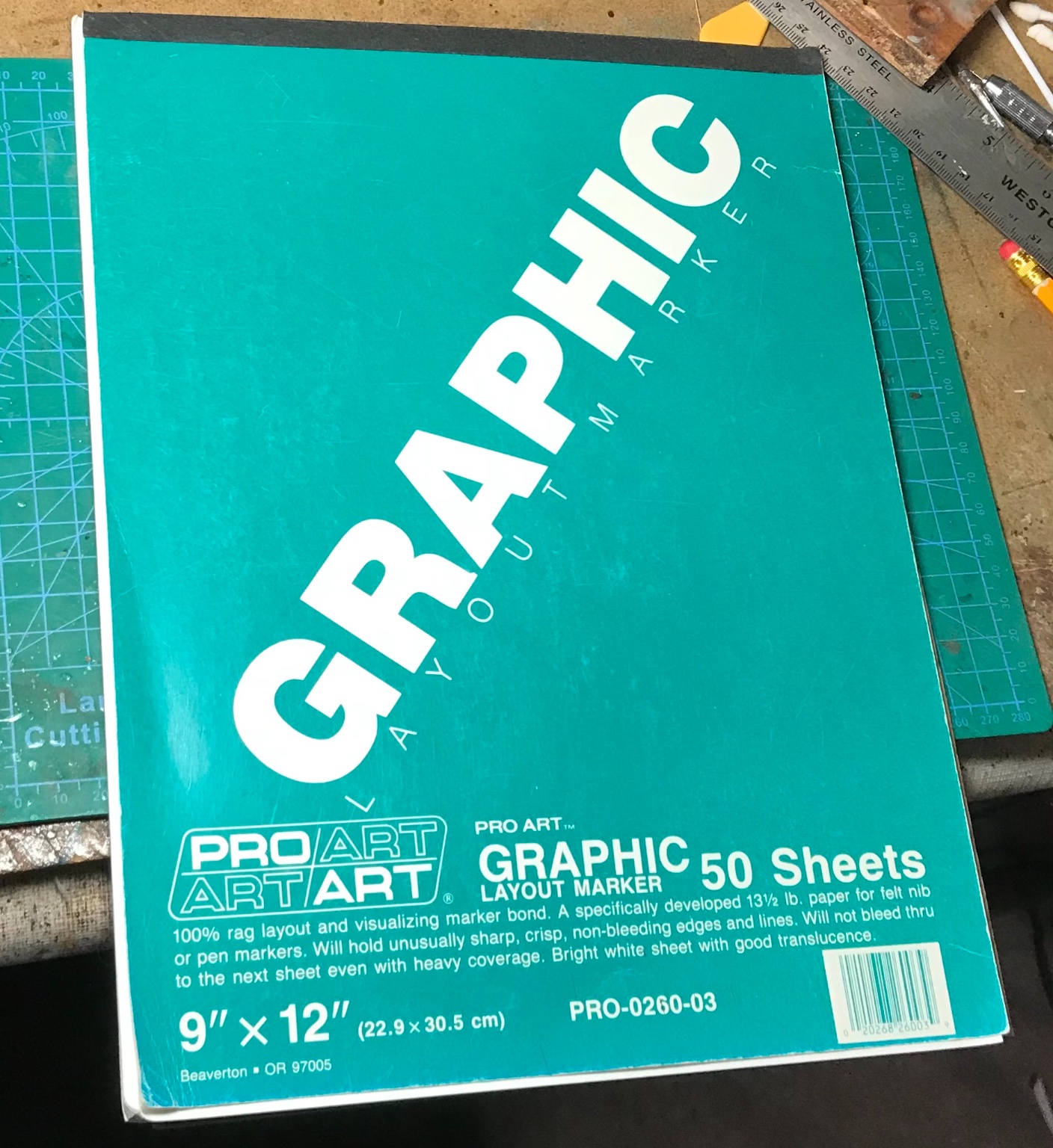
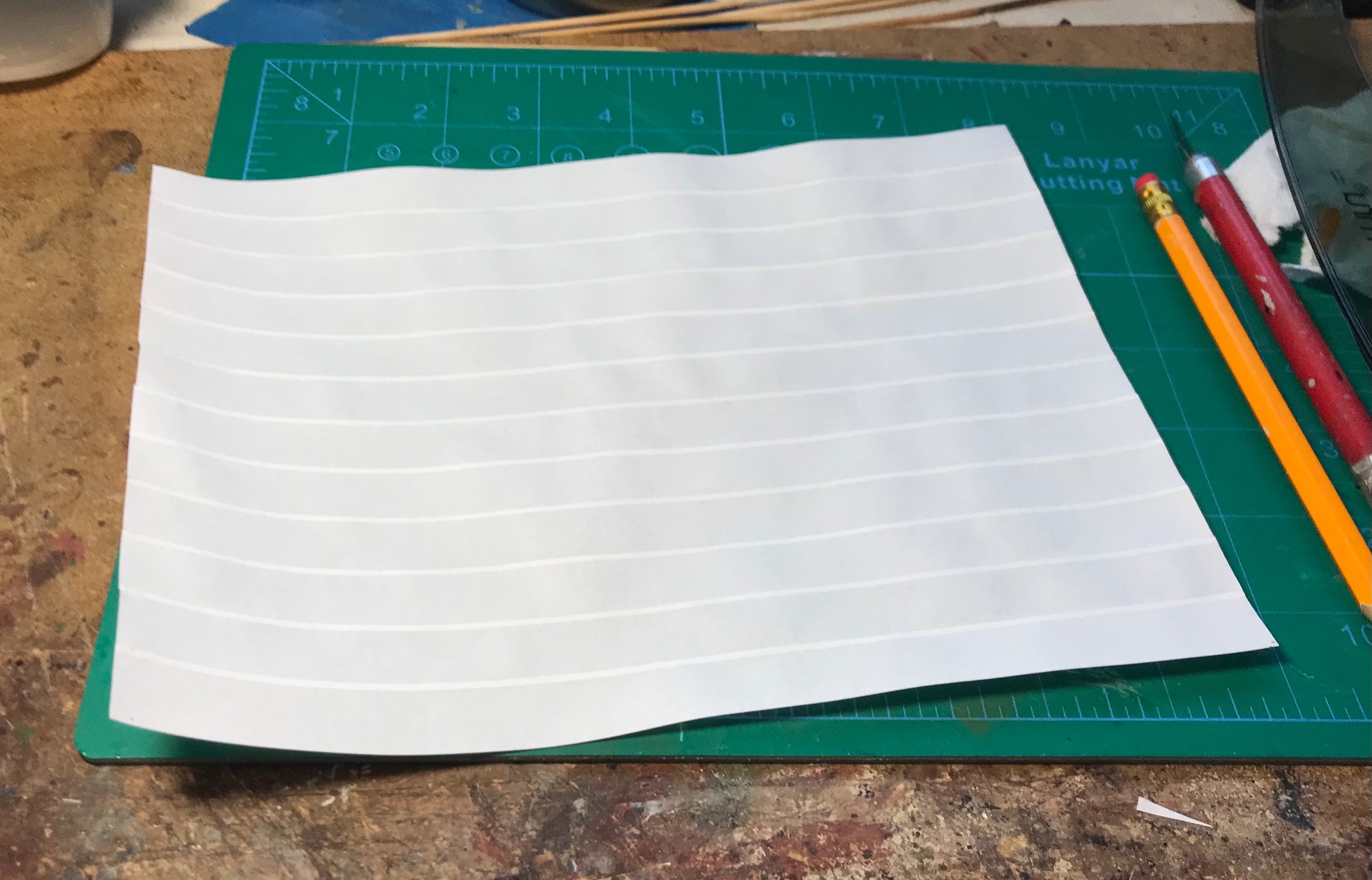
Wefalck, you will have to recalculate. I wish we used the European system for paper size. Ours is totally crazy! In the US system, the size of a sheet of paper for determining weight in a "ream" is not what is listed on the package (i.e. the dimensions of the paper as it is sold is not the same as the dimensions of the paper when it is weighed). The dimensions also vary by type of paper. So, assuming graphic marker paper is considered "sketch paper" when determining weight, the size of a sheet in a 500-sheet ream is 25 inches by 36 inches (635mm x 914.4mm). If this paper is not considered "sketch paper," then is is most likely considered "drawing paper." A sheet of "drawing paper" is 24 inches by 36 inches (609.6mm x 914.4mm) when determining the weight of a ream. I'm not sure of my skills using a micrometer, but I got 0.10mm for the thickness of a sheet of common copy paper and 0.065mm on the paper I use for sails...
-
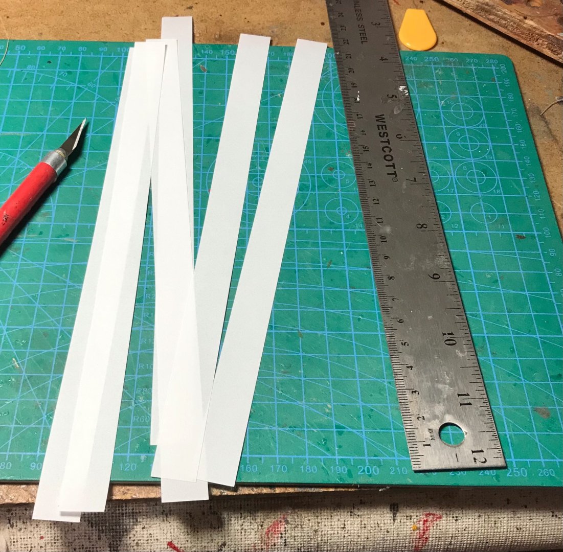
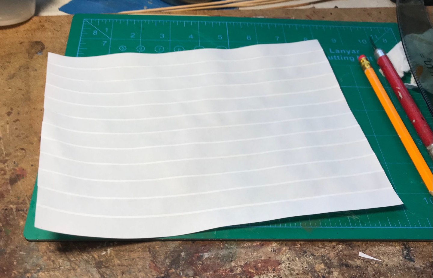
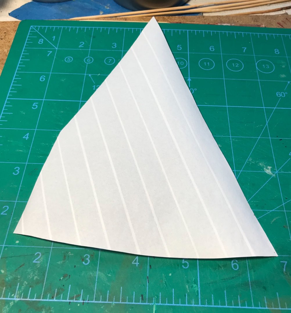
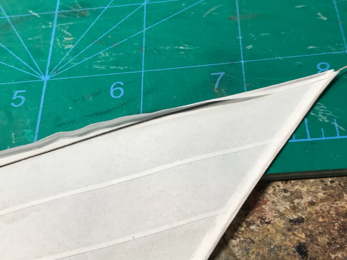
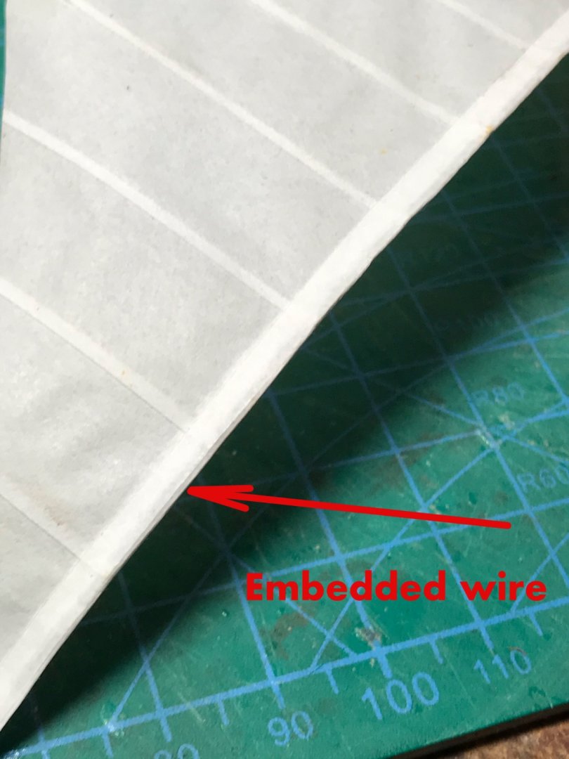
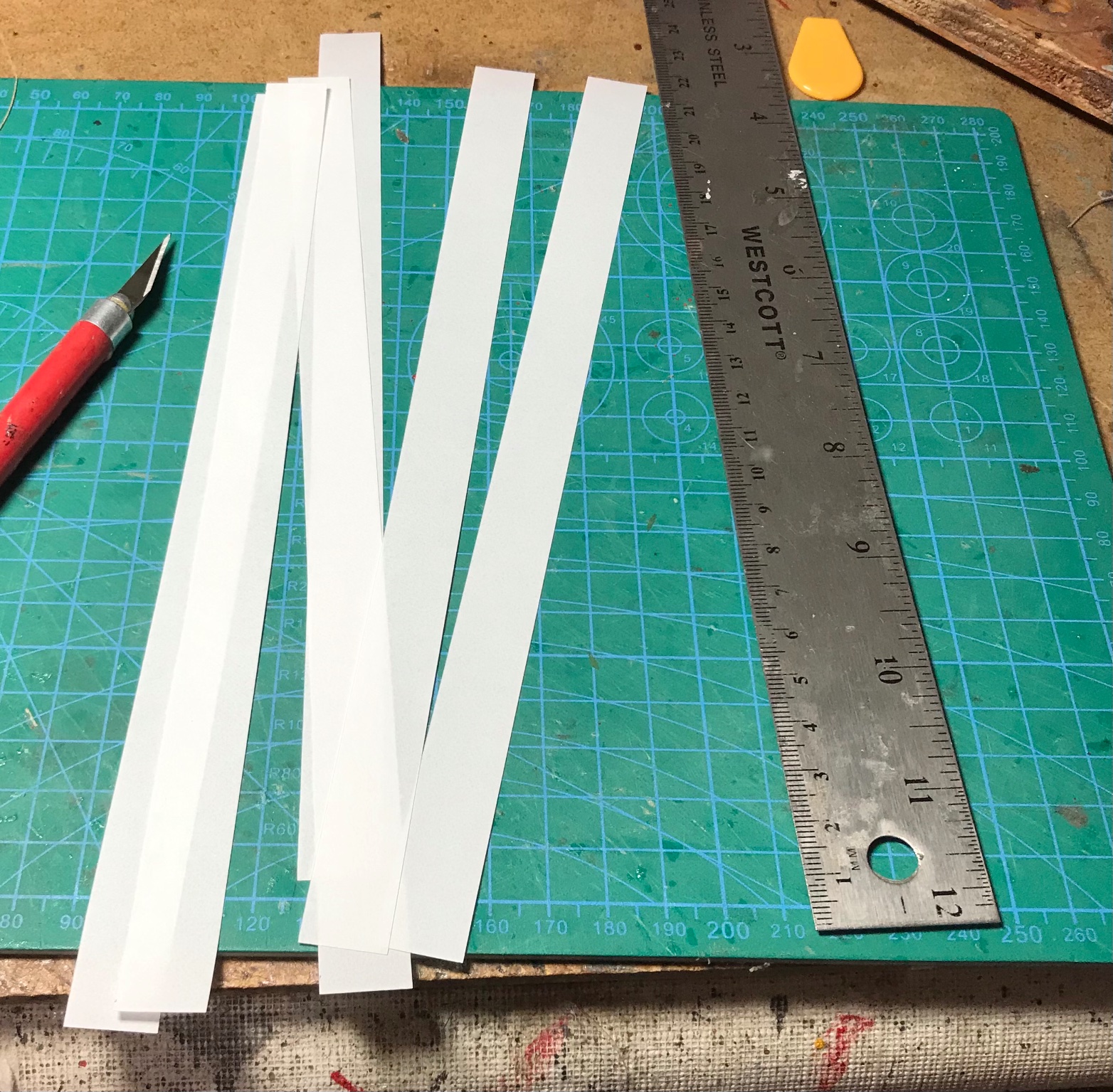
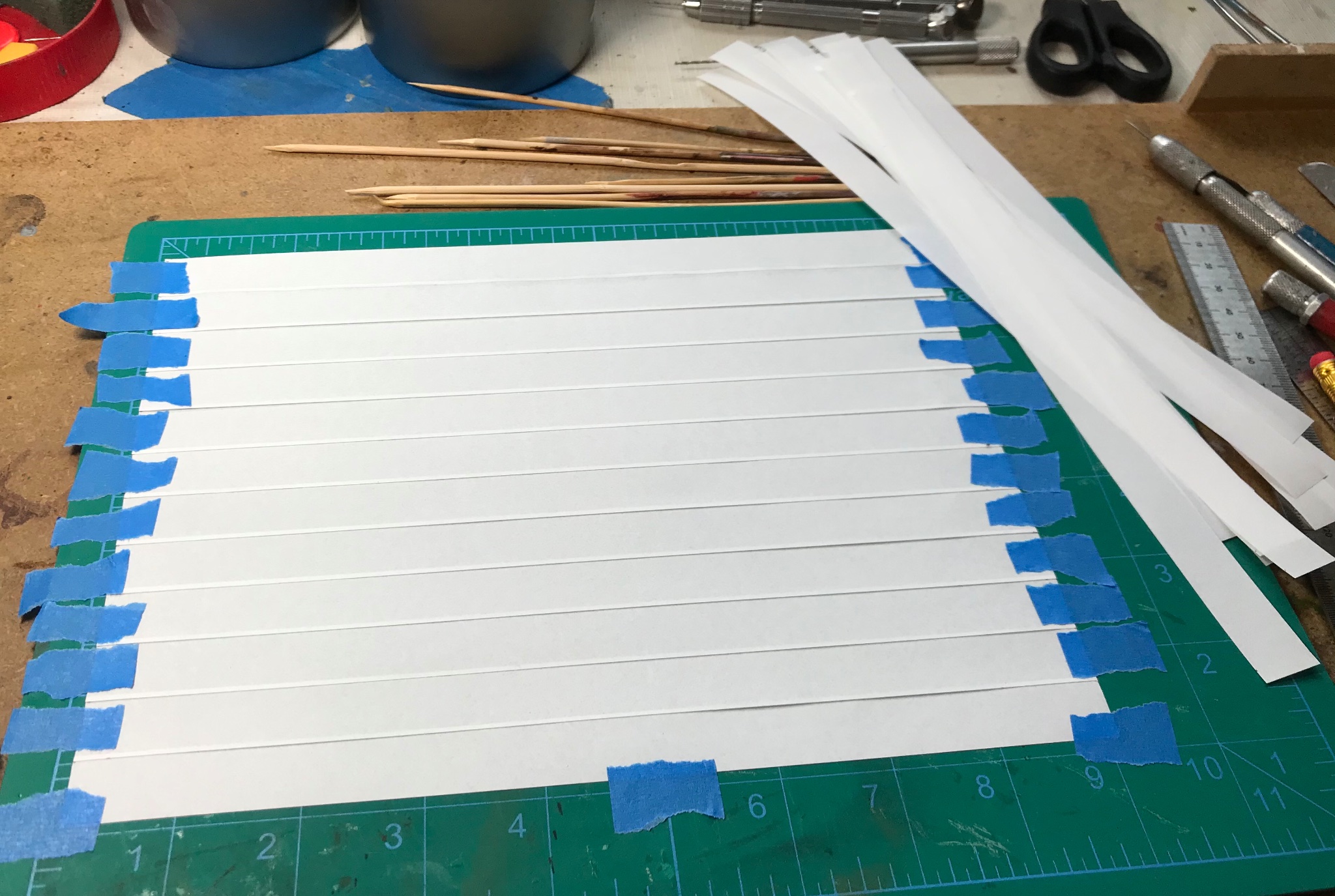
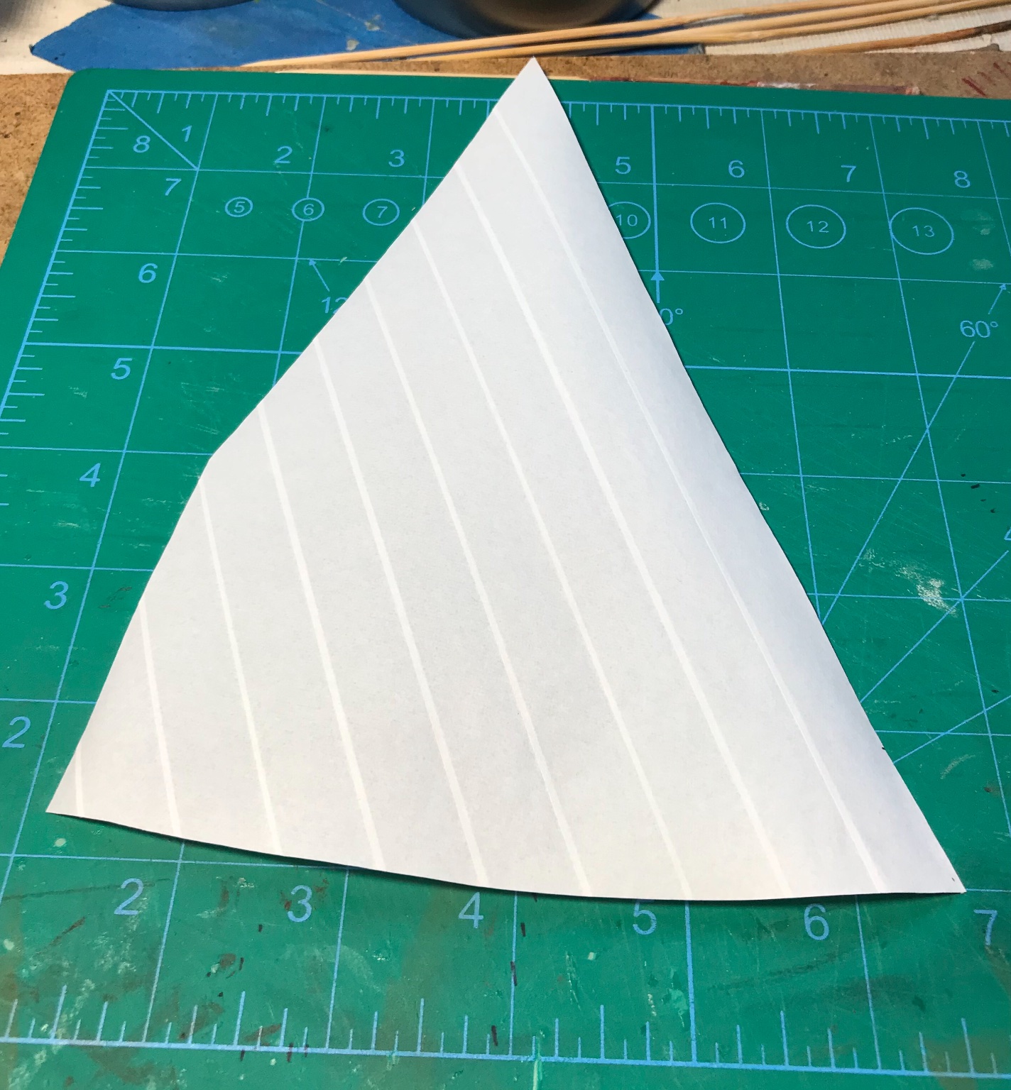
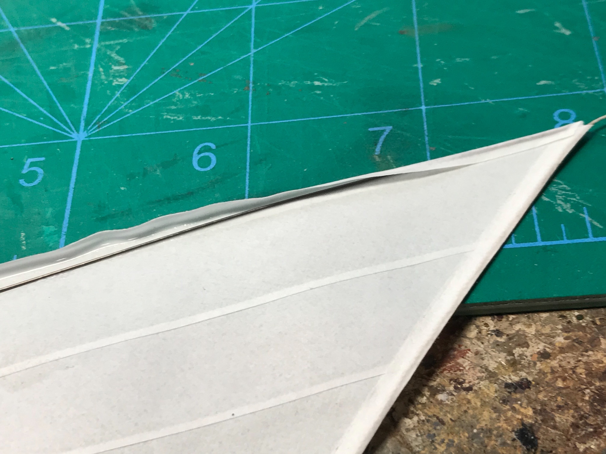
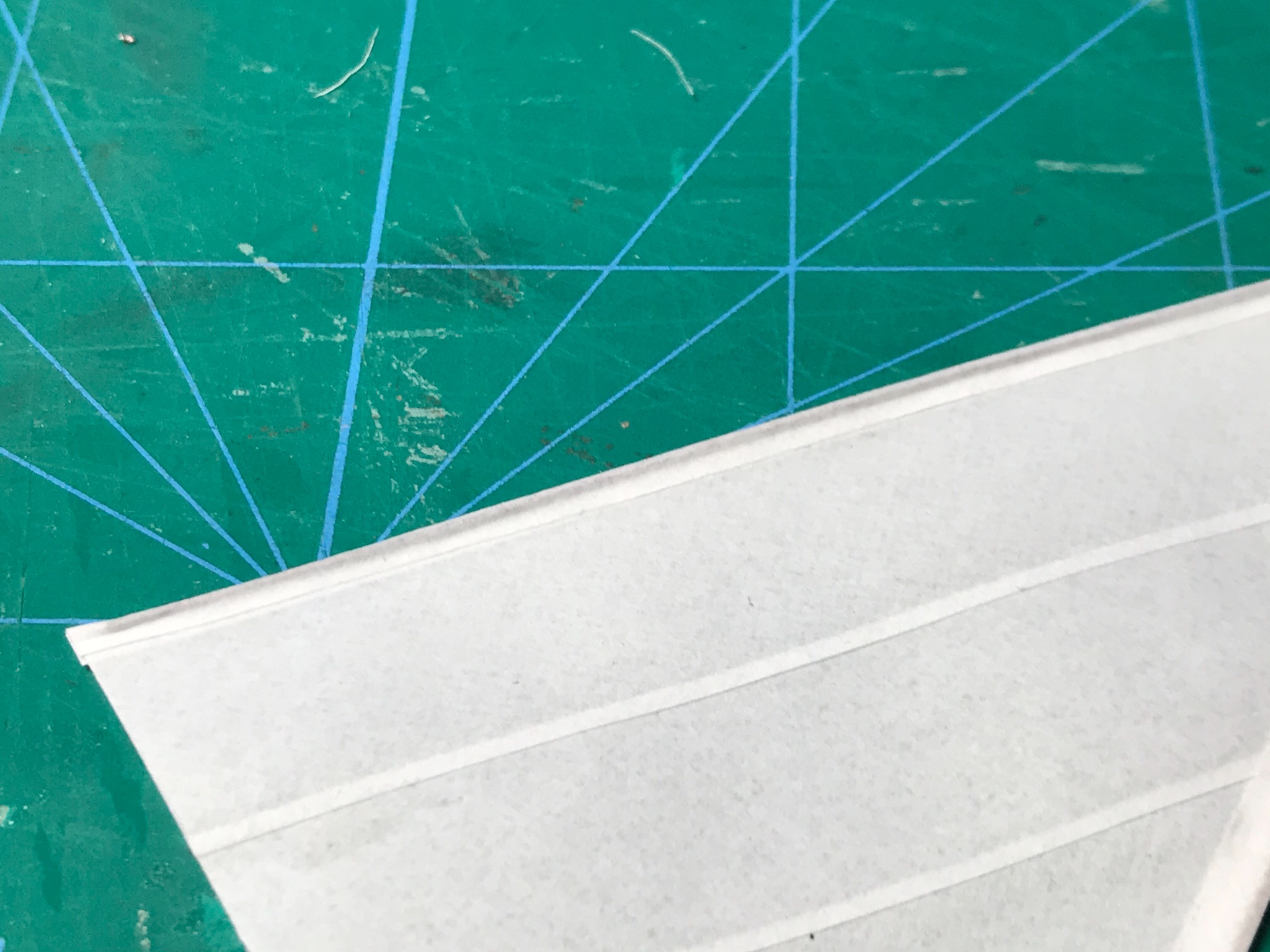
Thanks EKE. Here's some more info on the sail building... I found this graphic marker paper makes great raw material for sails... Cutting the strips... I find taping everything down before gluing helps to keep the panel lines even. Gluing is done with diluted white (PA) glue applied with a small brush. Excess glue is "dabbed" off (NOT rubbed) with cotton swabs... A finished sheet. At this stage, I sometimes have to go back and re-glue short segments of seams that did not stick with the initial gluing... I use patterns cut from copier paper (not shown) to get the final sail size and shape before I cut out the sail from the sheet. At this point, I sometimes put the sail between two paper towels and hit them with stream from a clothes iron to give them a little wrinkled texture. You have to be careful because the steam can re-activate the glue and make it stick to the paper towels a little. The paper towels protect the sails from direct contact with the iron. Don't want to get glue on the iron! I use strips of the graphic marker paper, folded in half ( the long way), as edge trim pieces. Both the wire and/or rope loops can be glued inside the seams. The trim is glued with the same diluted white glue. That's it!