HOLIDAY DONATION DRIVE - SUPPORT MSW - DO YOUR PART TO KEEP THIS GREAT FORUM GOING! (Only 13 donations so far - C'mon guys!)
×

Gbmodeler
-
Posts
465 -
Joined
-
Last visited
Content Type
Profiles
Forums
Gallery
Events
Everything posted by Gbmodeler
-
 Here's the pilot house after the "glass" and roof were applied. You can also see the finished door...
-
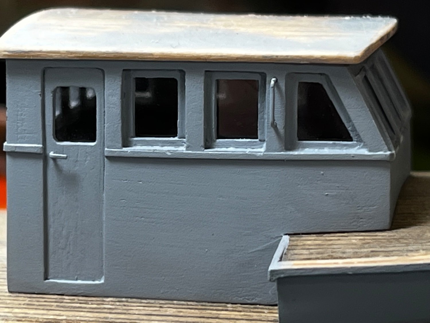
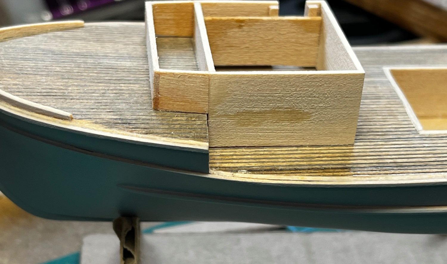
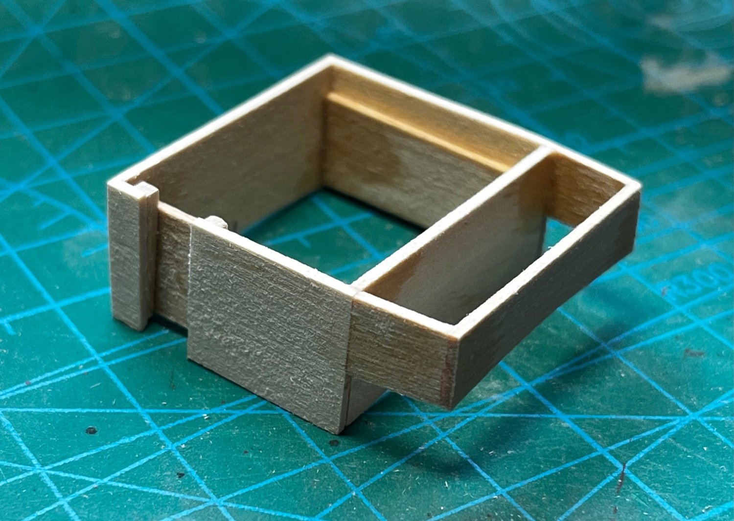
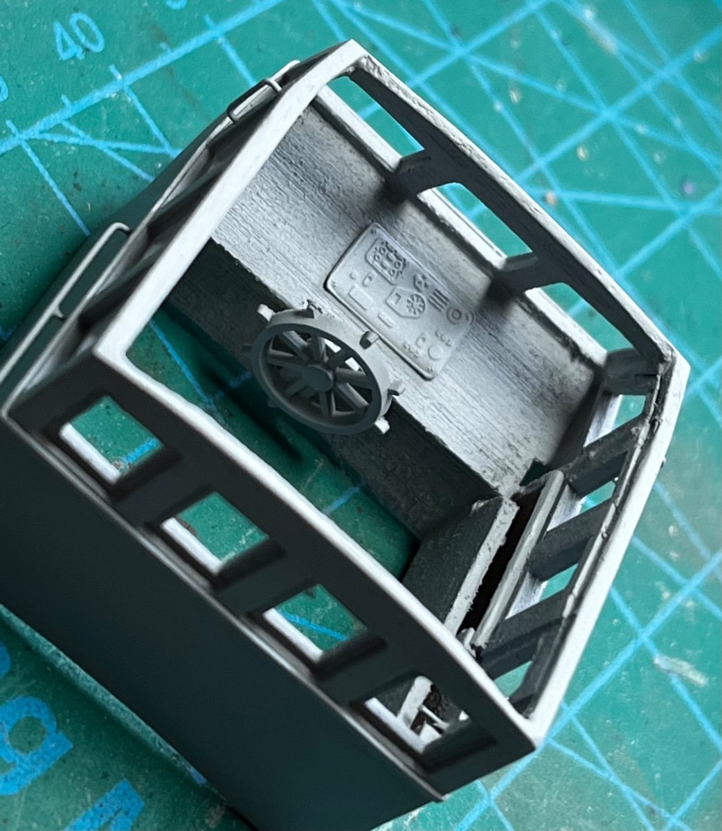
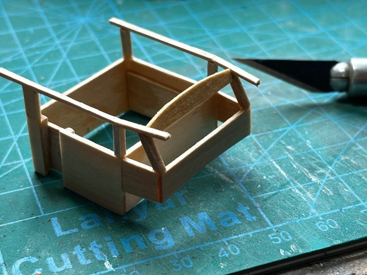
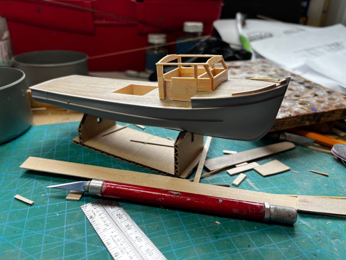
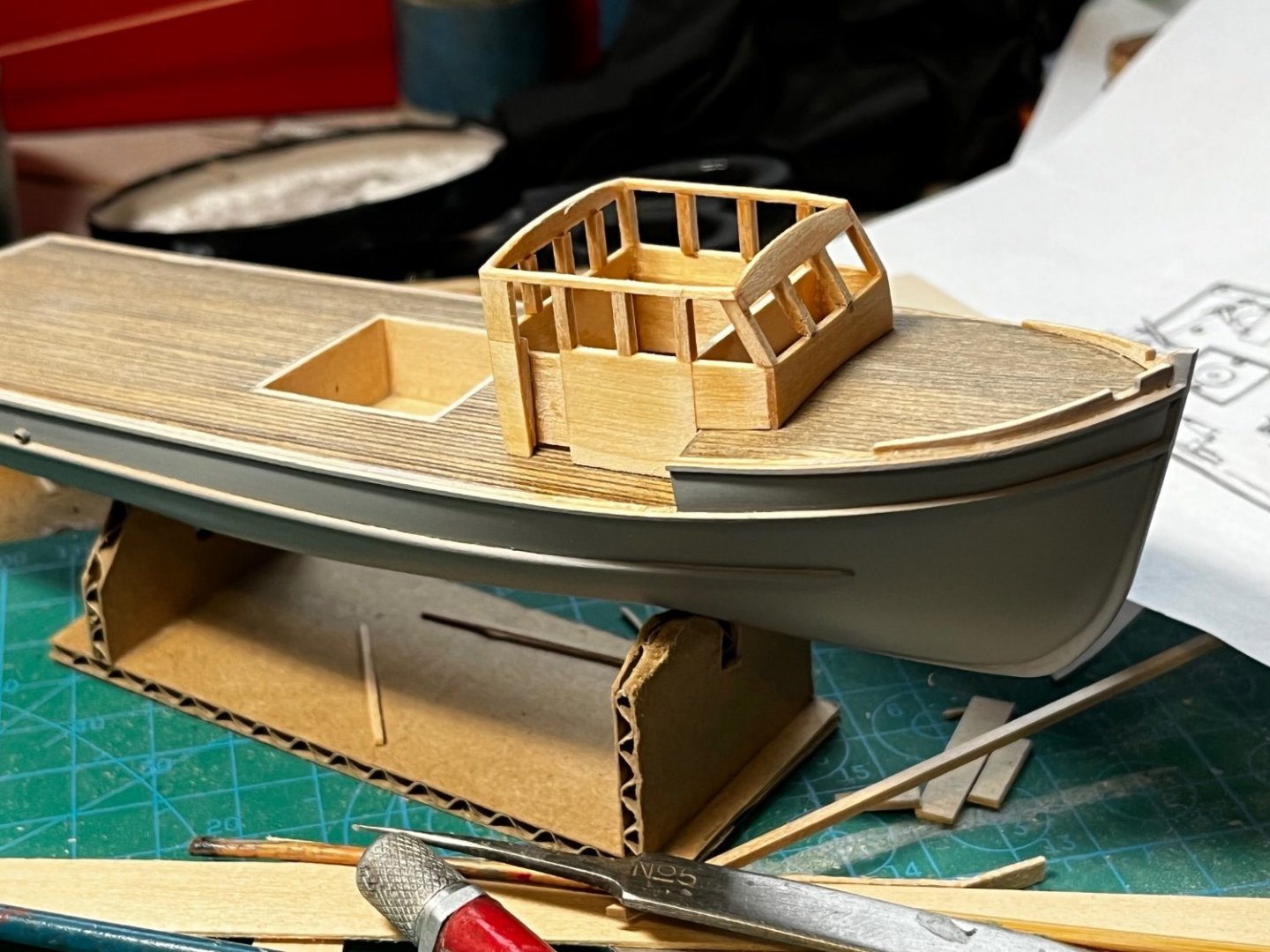
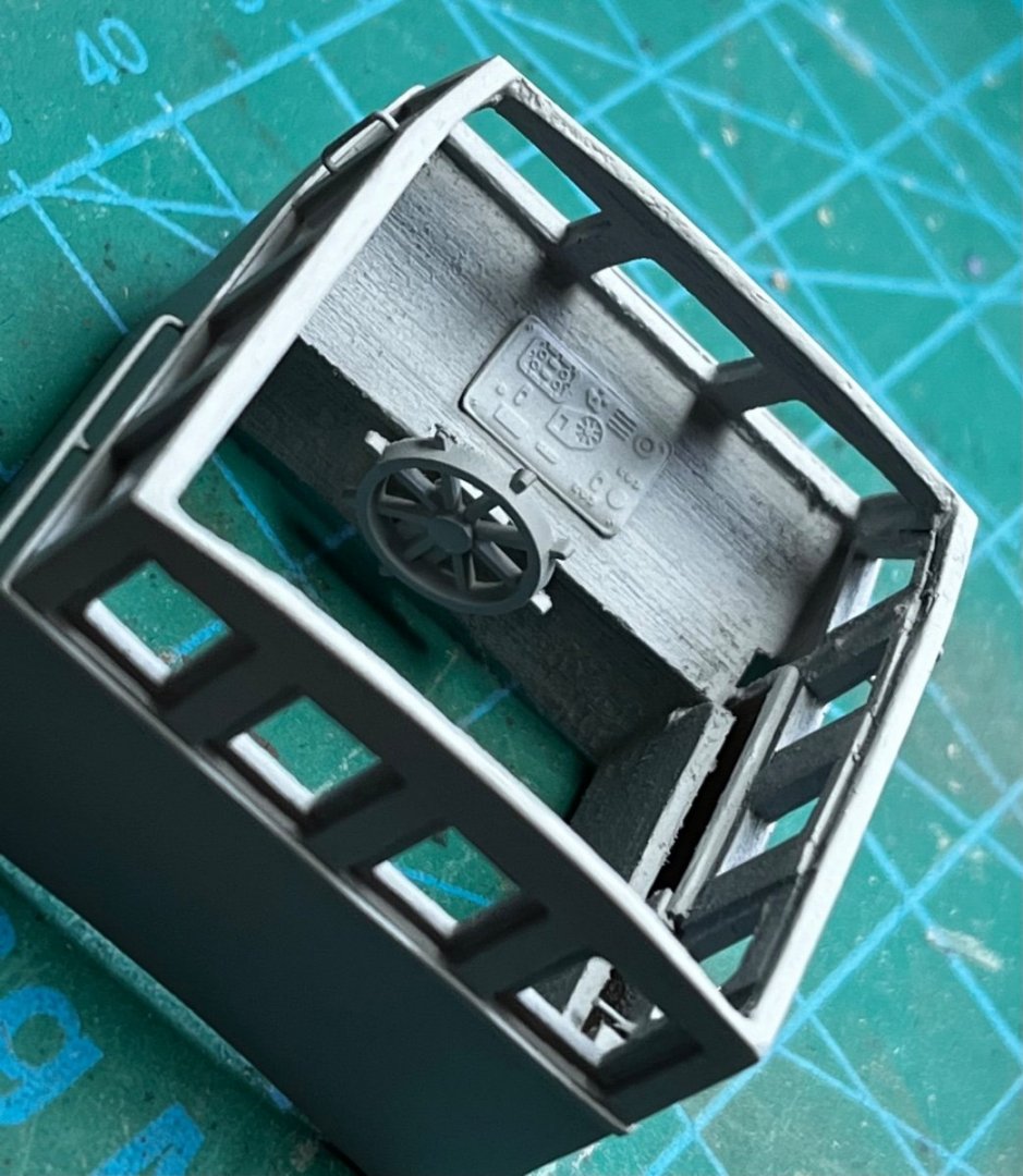
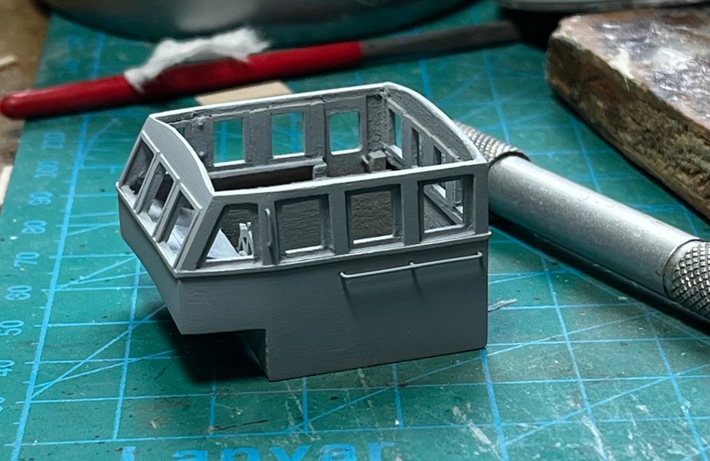
The pilot house was the next thing to tackle. Again, using 1/32" basswood sheet, it was "built-up" after closely studying drawings and photographs I found on the internet. The pilot house door on the starboard side was the first problem. How do I get a structure, squared and true, with the gap created by a place where a door has to go? The problem was solved by using an inner wall. I put an inner wall on the port side too, to add greater strength to the structure. Here's the door gap, and how the inner walls were used. The bottom of the pilot house had to be shaped to account for the camber in the deck. I use a 1/2" dowel with sandpaper glued to it to give me a large round file. The pilot house is all windows. This was a challenge to keep everything at the proper angle, or straight... She slowly came together... After assembly, but before attaching the roof, I primed and painted the pilot house. This was so I could put "glass" in the windows. Adding window glass would be easier with the roof off. A clear plastic tomato container volunteered to be the "glass". It was cut into flat strips, dipped in clear acrylic floor polish, and hung up to dry over night. Window panes were then cut from the strips and glued in place. Sorry I didn't take any photos of that process...🫤 With all the windows, I figured you could see into the pilot house after it was done. More old photo etch served as a dashboard, and a helm was found in the spare parts... Grab rails were crafted from brass rod...

-
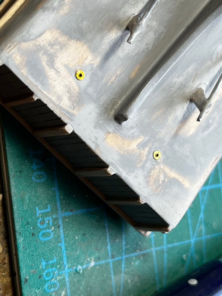
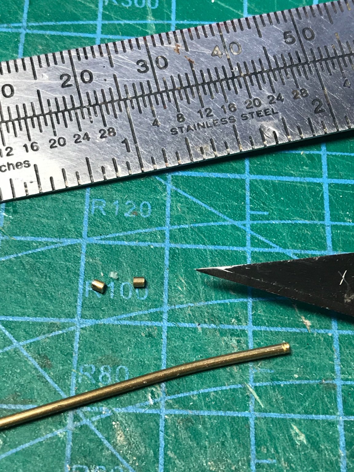
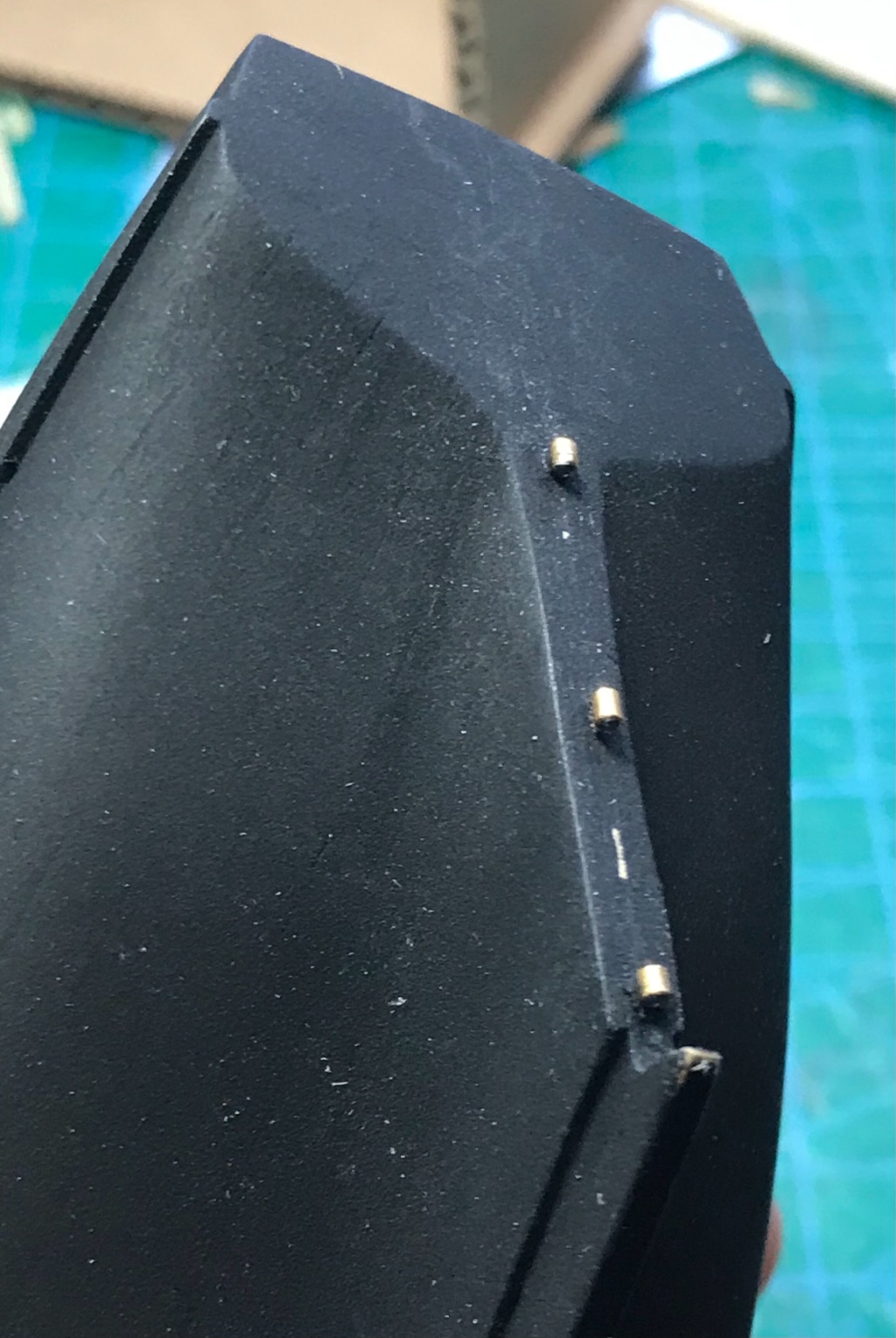
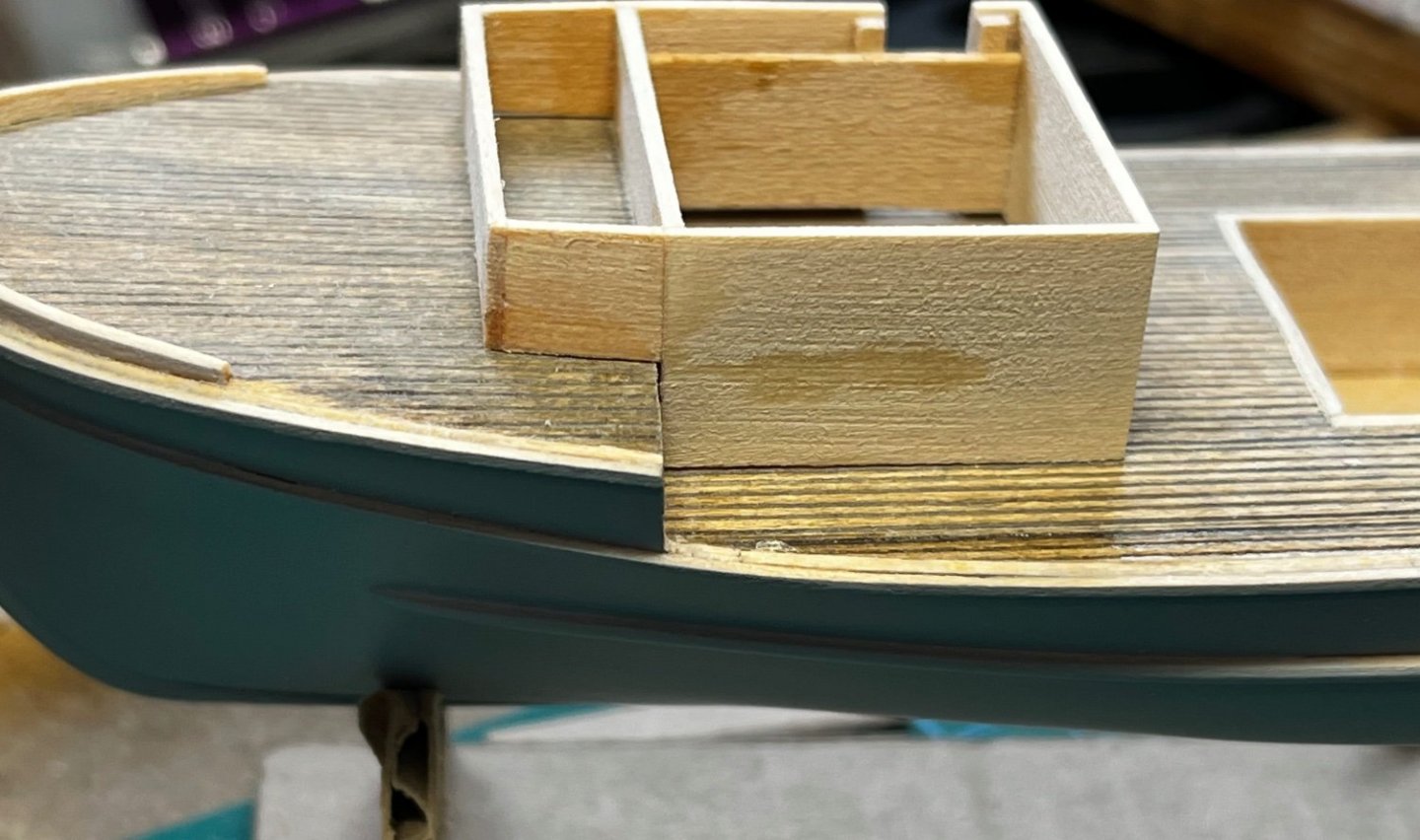
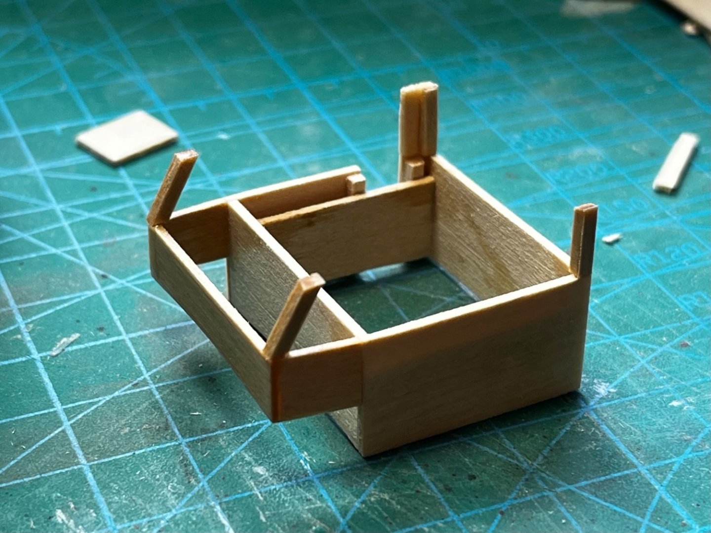
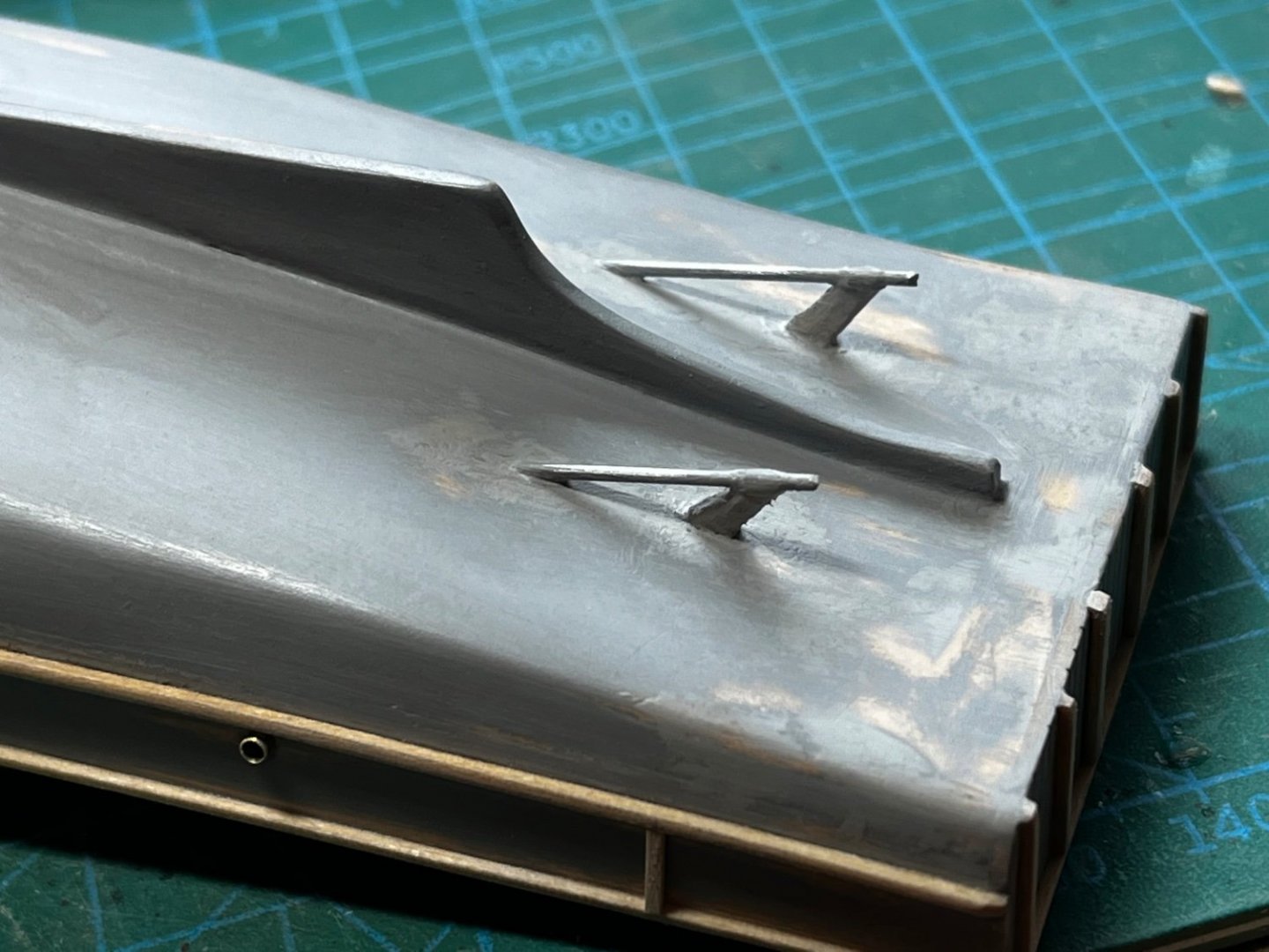
Along with the planking and trim, I shaped and added a keel made from 1/32" basswood sheet. The propeller shafts were made from piano wire, while the shaft brackets were made from little bits of the 1/32" basswood. Years ago, I learned that cornstarch mixed with super glue was a good filler for air-holes in resin models. I've been using that for recipe in other applications for years, and really like it. Here, I used it to make the tubes the propeller shafts run through at the end of the brackets (a glob of filler was put around the shaft and filed to shape after the slurry dried)... Next, the hold for the cable reel was located and cut out from the deck, paneled with basswood sheet, and trimmed. Bilge pipes on the sides were made from brass tube. I have accumulated 20+ years of left-over photo-etch parts from armor modeling. Whenever I need something, I look through the tons of photo-etch for an appropriate part. In this case, antenna rings from some long forgotten tank model serve perfectly for rudder post holes...

-
I have not heard about the MSIs, so thanks for the info. 😃
-
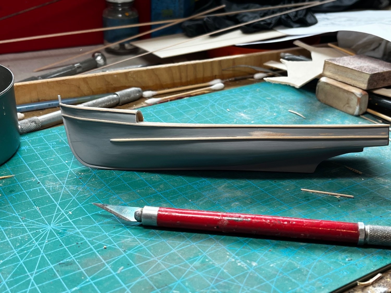
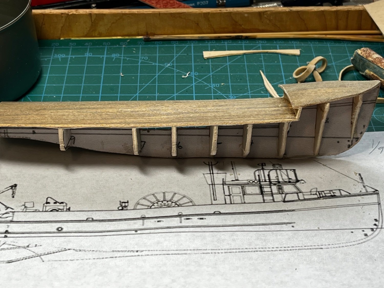
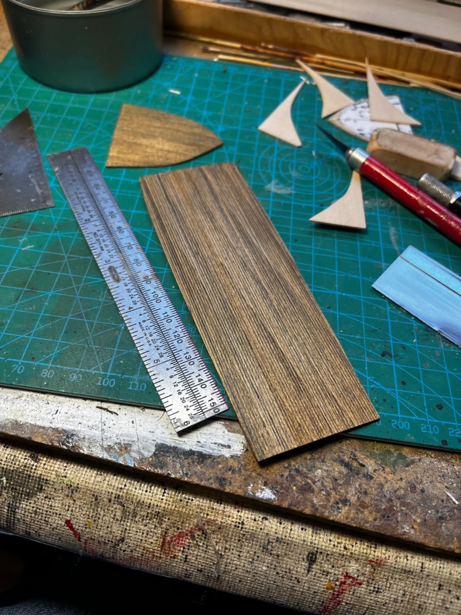
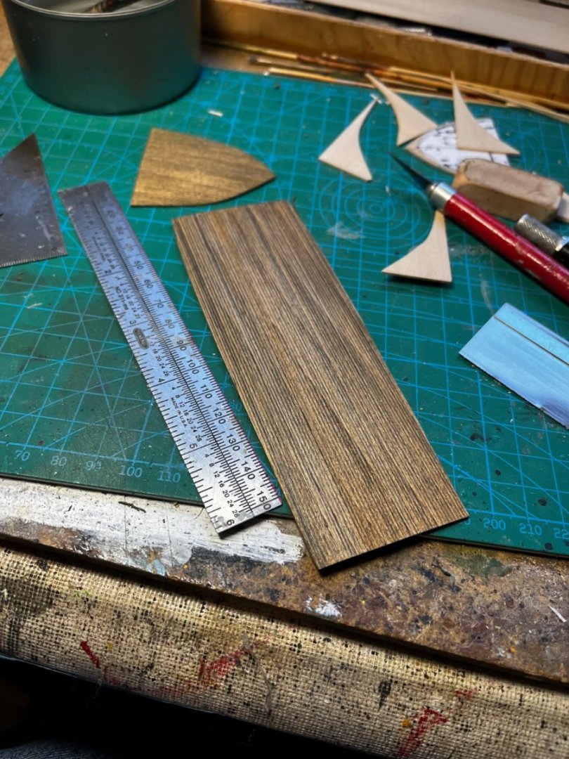
I have to admit, this was the easiest planking job I ever did. Since I planned to smooth and fill the hull anyway, I wasn't too worried about accuracy. I began making 3mm wide strips from 1/32" basswood sheet. After fixing the garboard strake, I just added the planks without tapering anything. They went on beautifully, with only one tapered cheater needed amidships at the curve of the hull. I then coated the hull with acrylic wood putty, diluted with tap water to make a thick slurry. After sanding everything smooth, I applied "Mr. Surfacer 1000", found any blemishes, and sanded them out. Here's the finished hull, with trim pieces starting to be added...


-
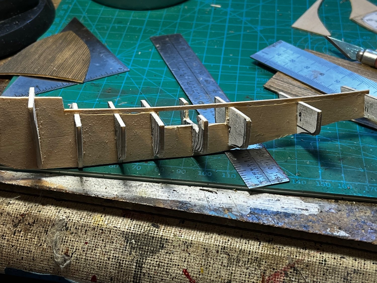
Thanks KeithAug. The shape of the hull does not change much from midships to the stern. It's such a little model, fewer frames were needed to achieve the overall shape (and strength needed).
-
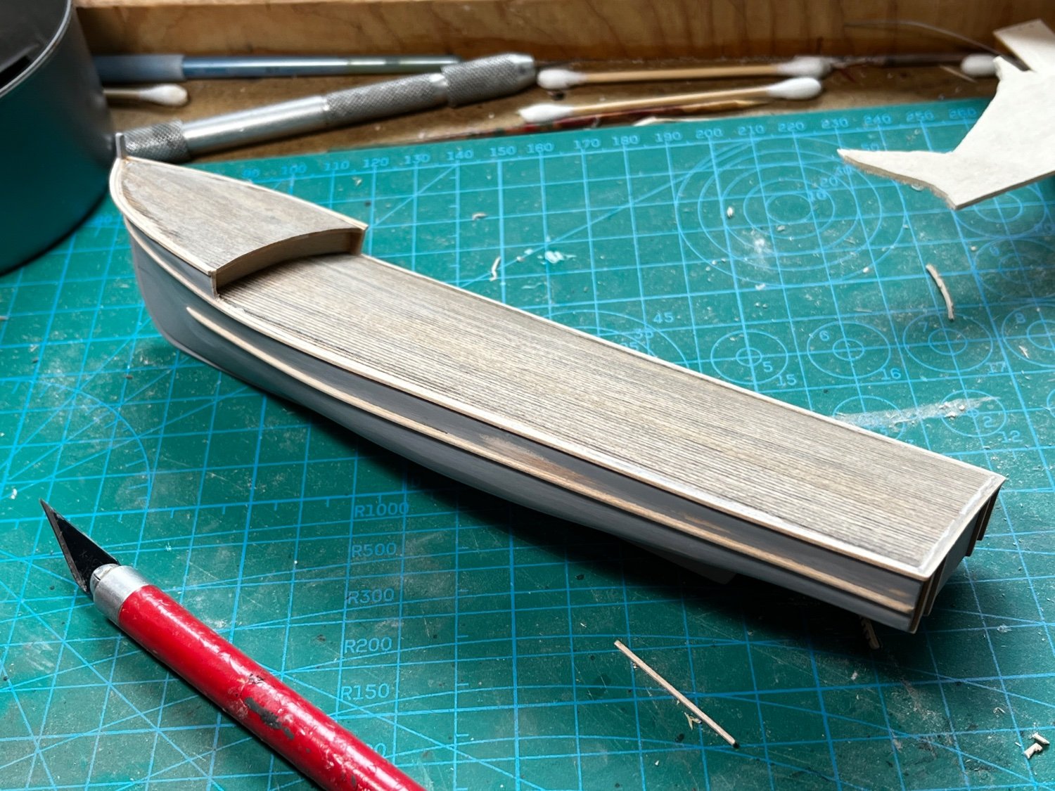
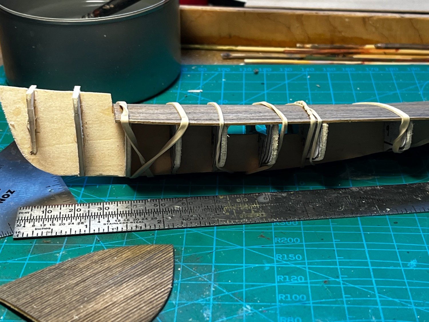
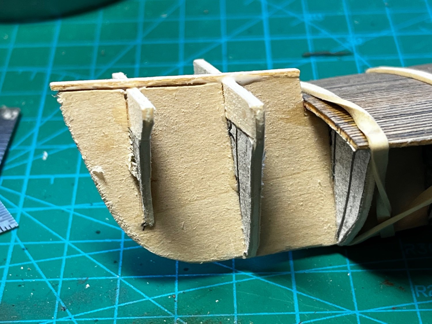
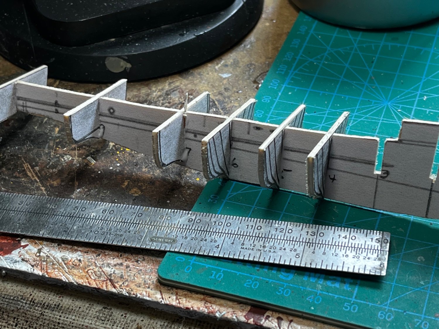
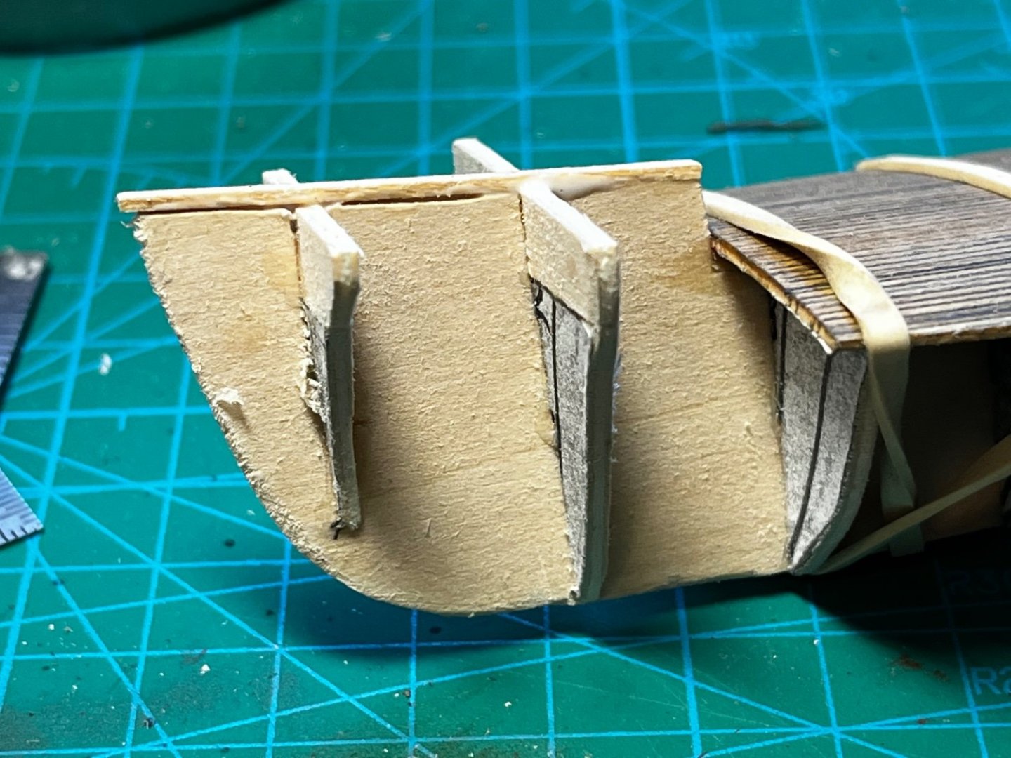
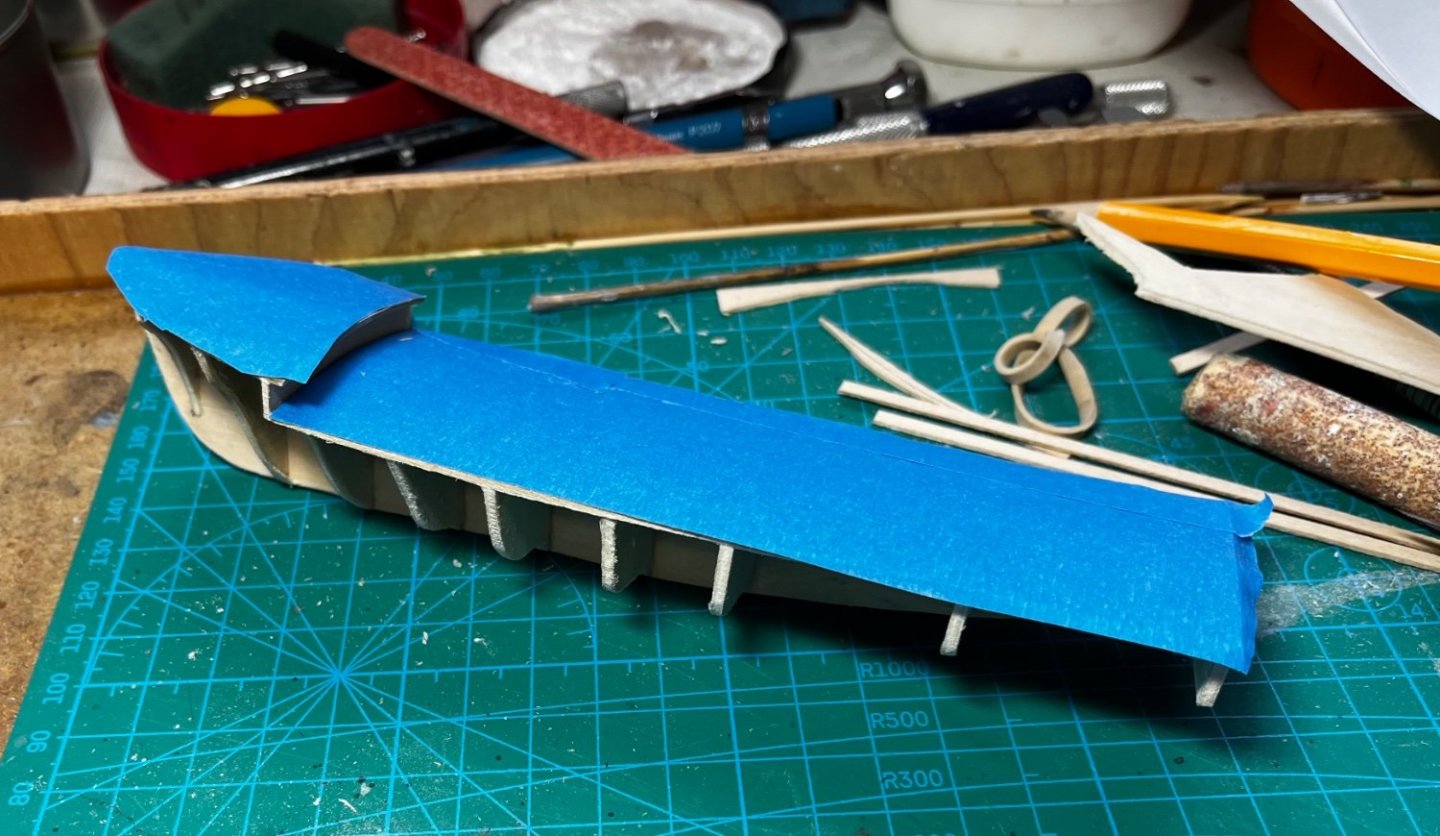
Continuing with the hull construction... The deck was glued to the top of the frame and held in place with rubber bands while the PVA glue dried... Before the deck was attached, a thin strip of wood was glued to the middle of the frame on both the long and short decks. This provided camber to the deck when it was applied... I forgot to mention that the frame was cut from thin basswood plywood (3-ply). The deck was from a solid sheet of 1/32" thick basswood. Before planking, the deck was protected with blue masking tape. I know my fingers will get glue prints all over everything if I don't protect it...


-
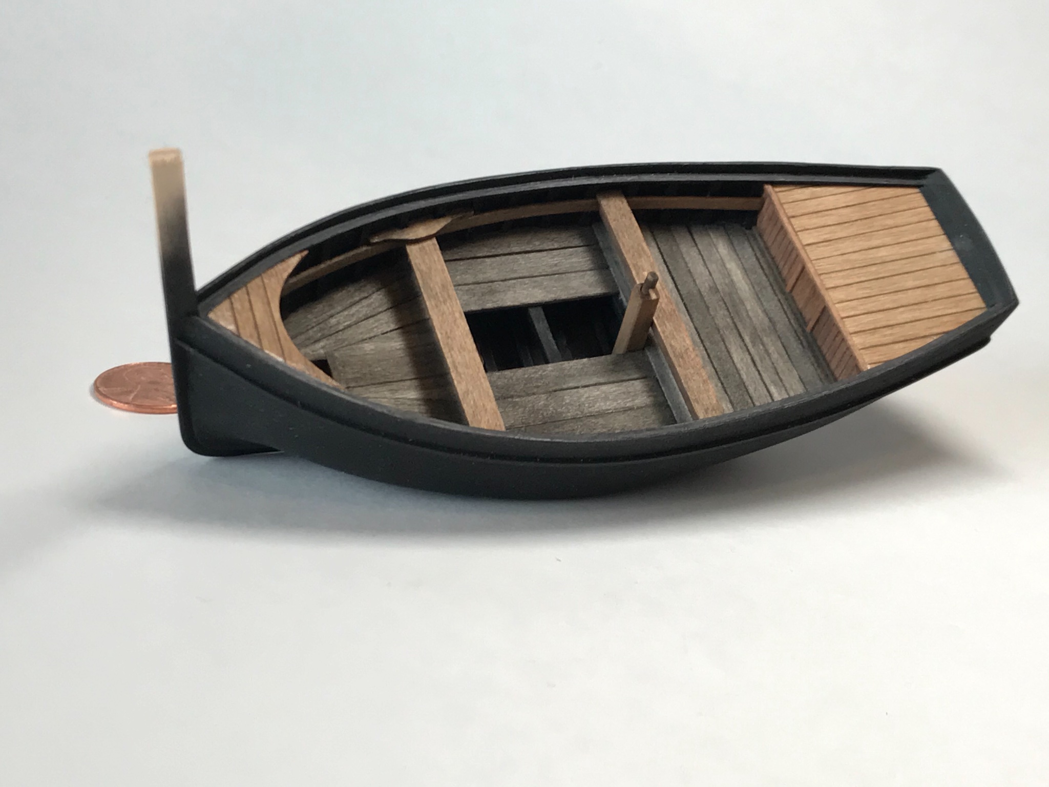
Model construction began with some line drawings and historical photos off the internet. I reconstructed the hull lines the best I could from these sources, but did not have any real plans to work with. Being a small model of a small boat, hull construction went quickly... Bulkhead on false keel construction. The model is only about 165mm long. I had to carve out a hole for the large electronic cable reel, which will be built later, and which is a predominate feature of the boat After the frame was completed, I started work on the deck. Planks were scribed by hand and colored with lead pencil. Then, the whole deck was lightly stained with a pine color.


-
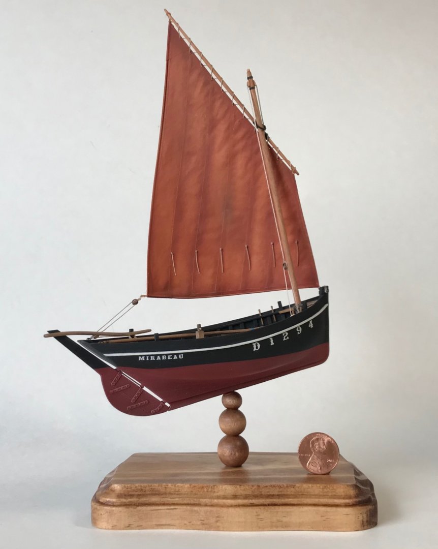
This is a model of a 57' mine sweeping boat from the 1950s. About 50 of these boats were constructed and used in Korea and Viet Nam. My father served on MSB 6, out of Charleston, SC in the early 1950s. While information, plans, and photos of these boats are skimpy, there is information available. The most detailed technical data I found on the internet is located at the Library of Congress web site at: https://tile.loc.gov/storage-services/master/pnp/habshaer/tx/tx1100/tx1140/data/tx1140data.pdf
-
Thanks so much Moab!
-
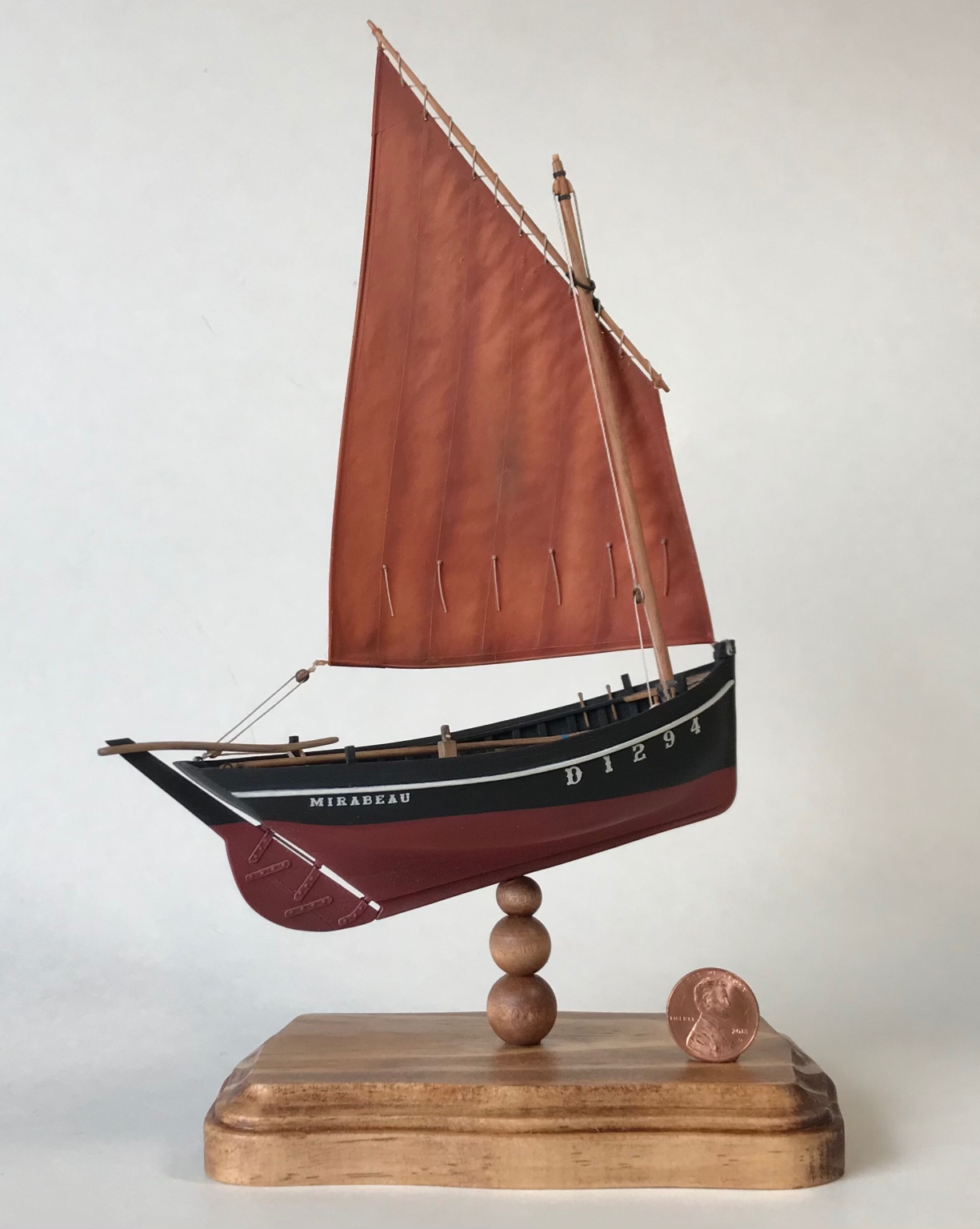
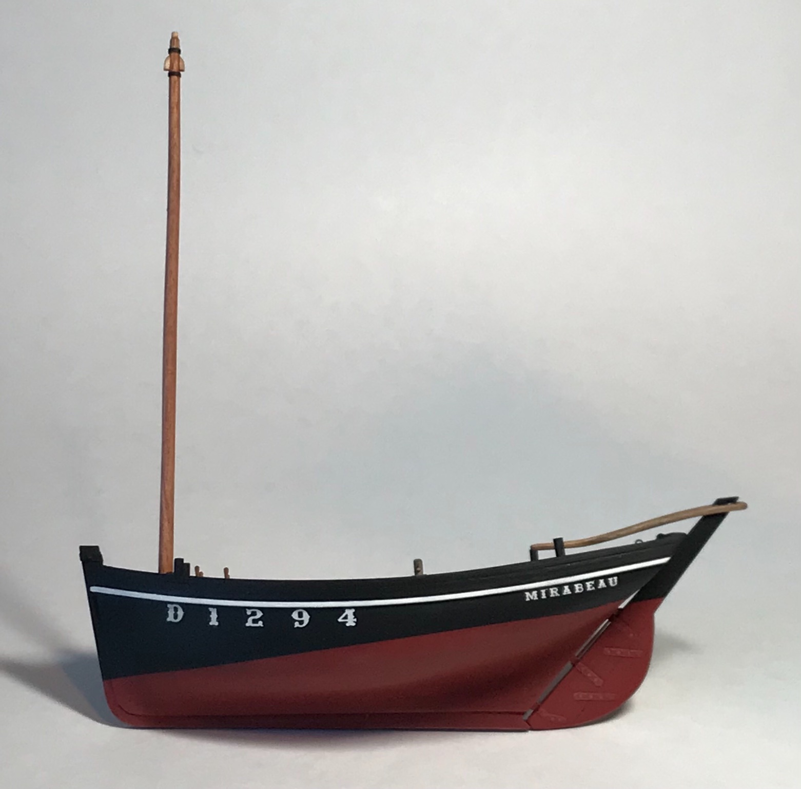
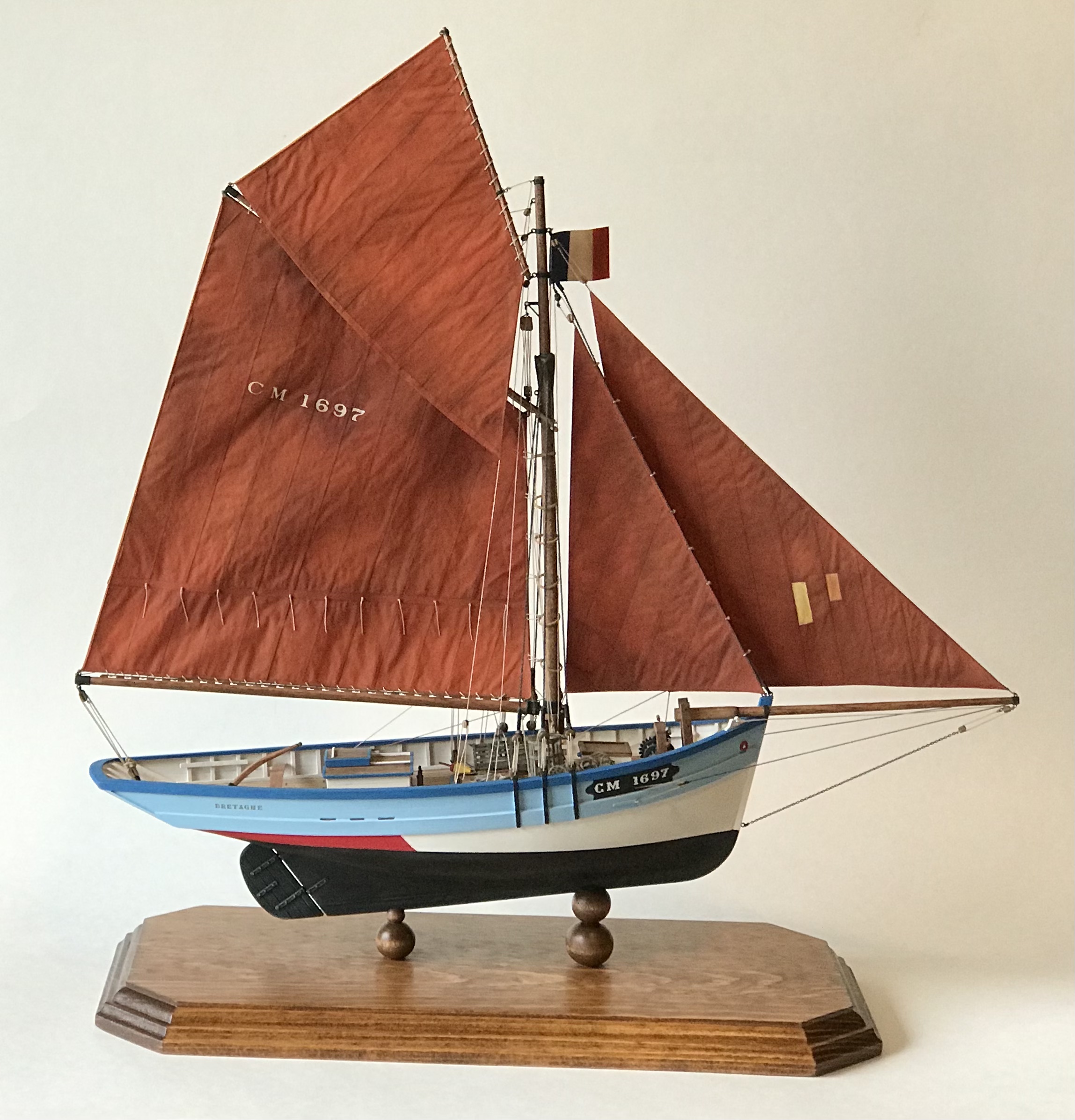
Fini! More photos of the completed model are in the gallery section at: https://modelshipworld.com/gallery/album/2294-misainier-french-fishing-boat-1906/
- 58 replies
-
- 15
-

-
Thanks Nirvana! No, GB is not Great Britain, but my initials (George B). I just really like these little French boats! Thanks for the nod. Go Zags!
-
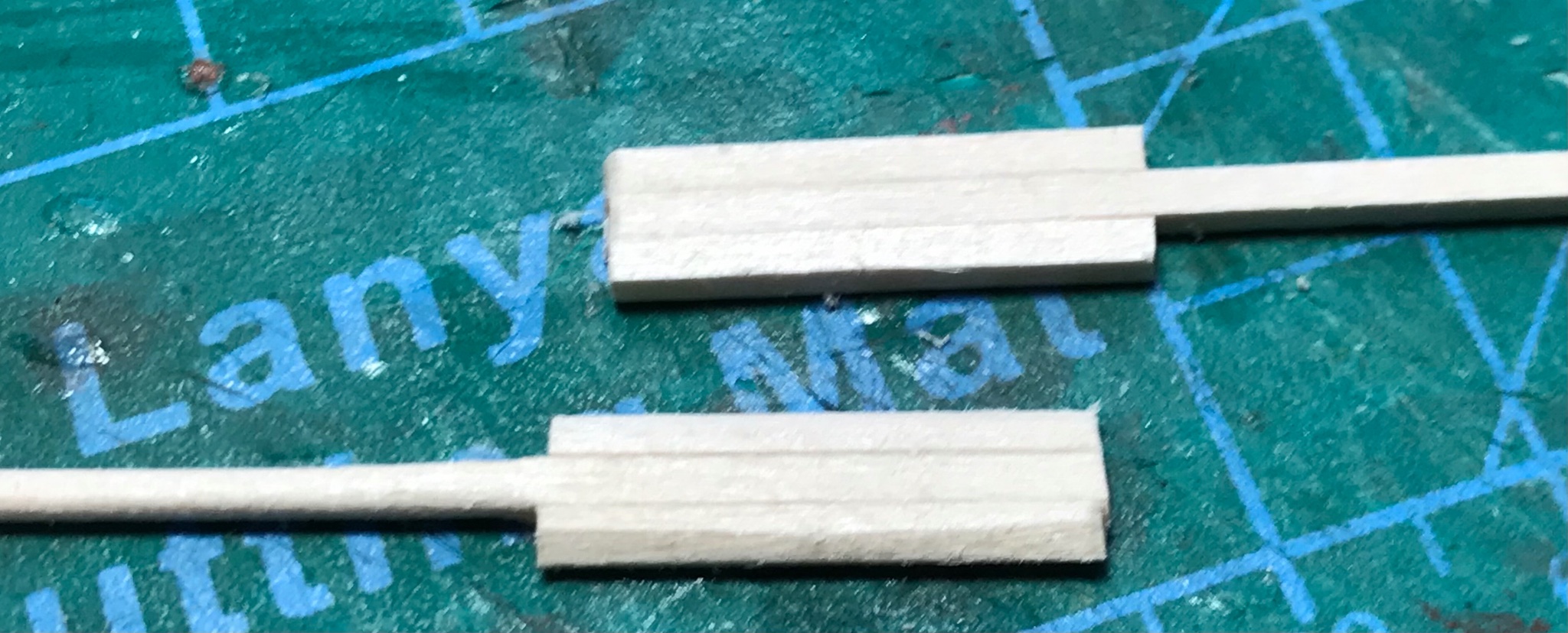
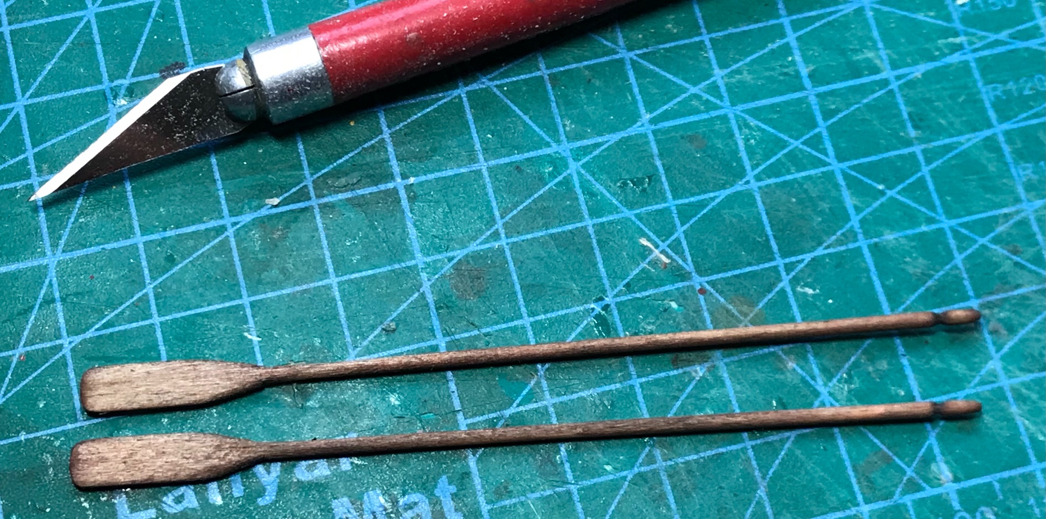
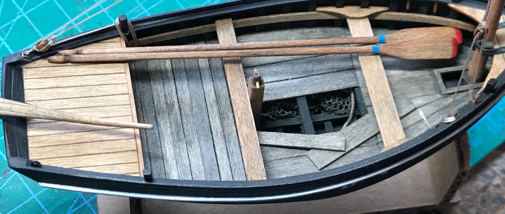
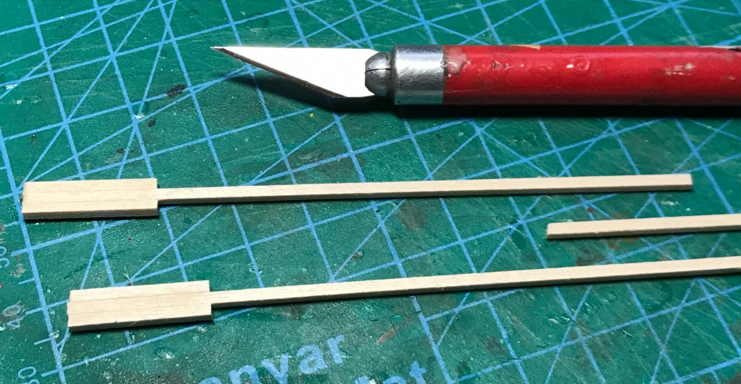
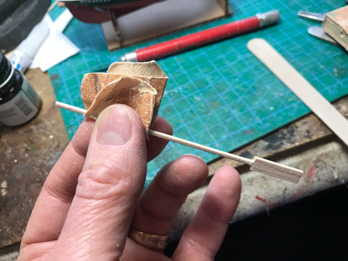
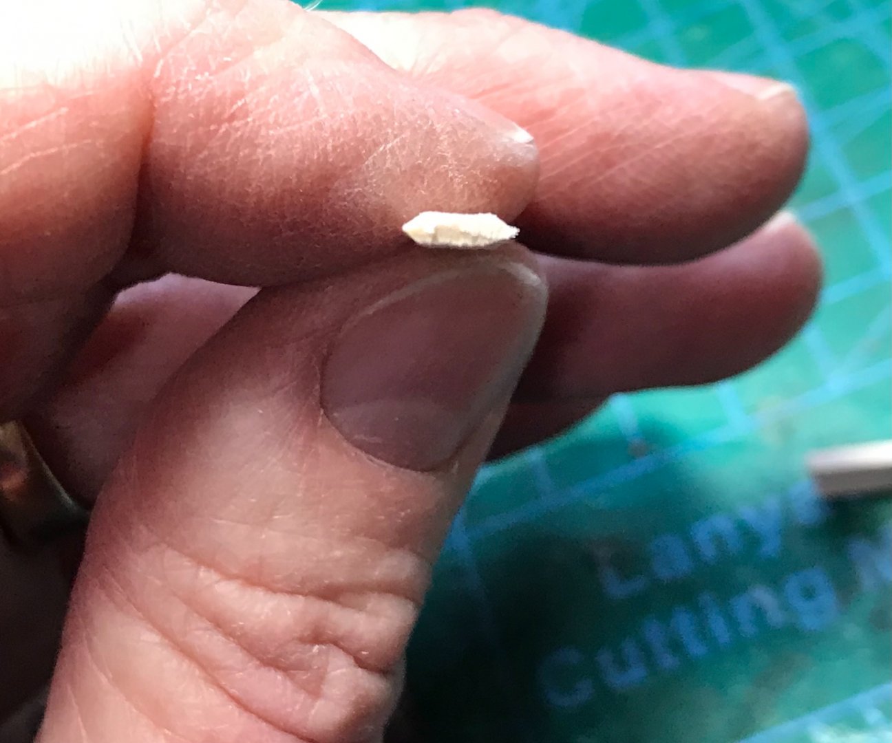
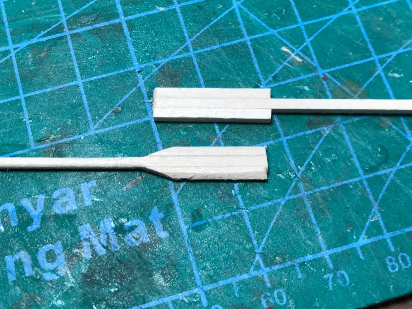
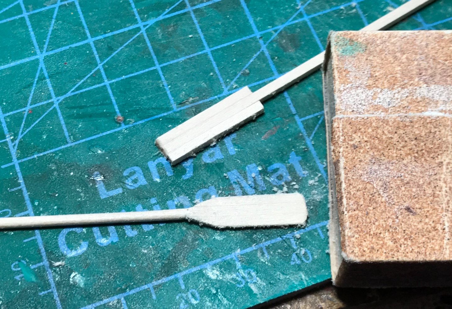
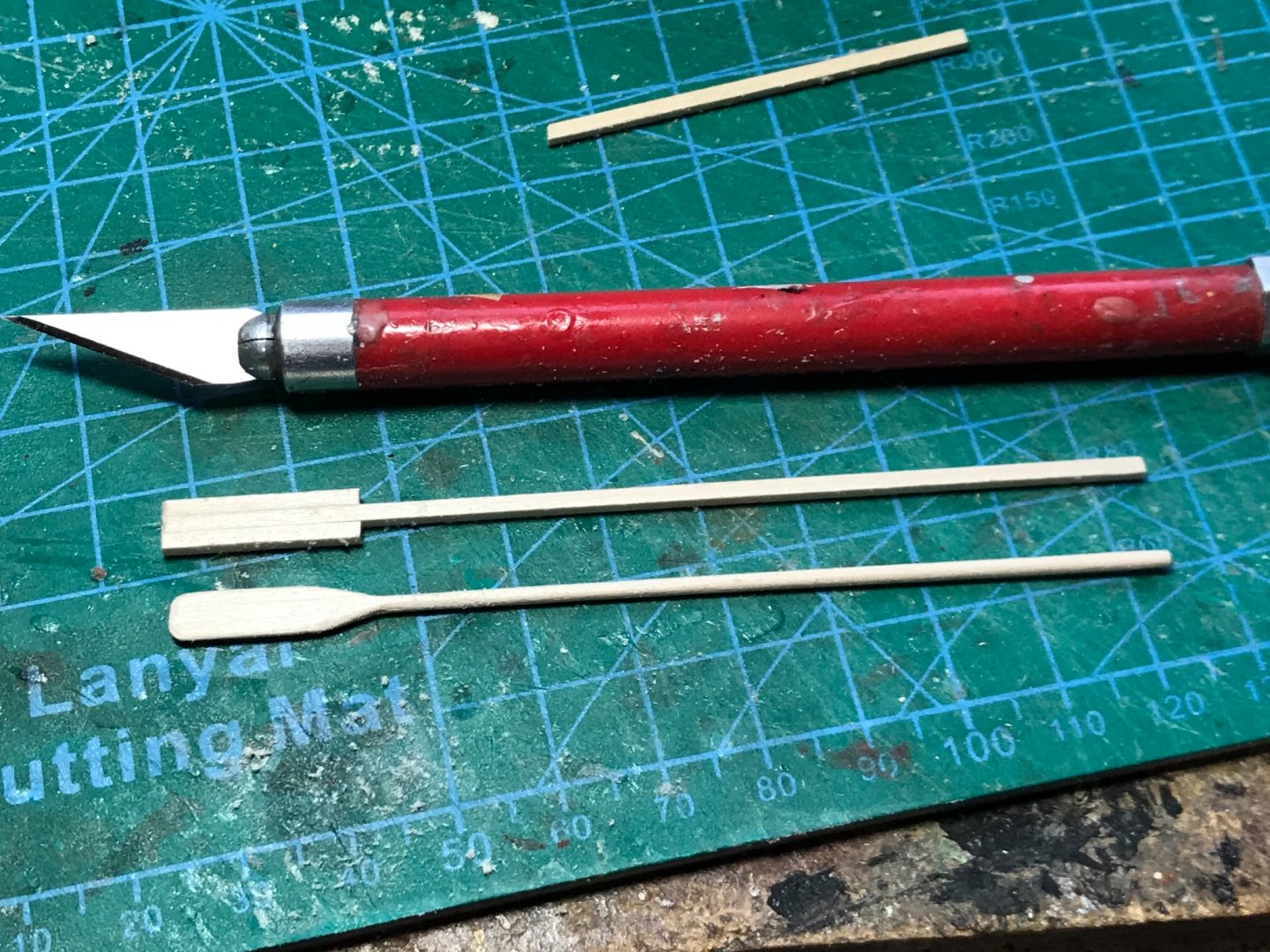
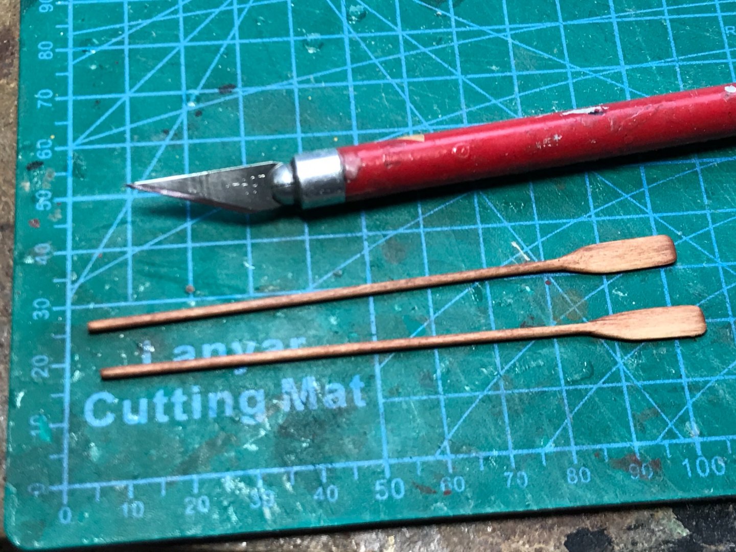
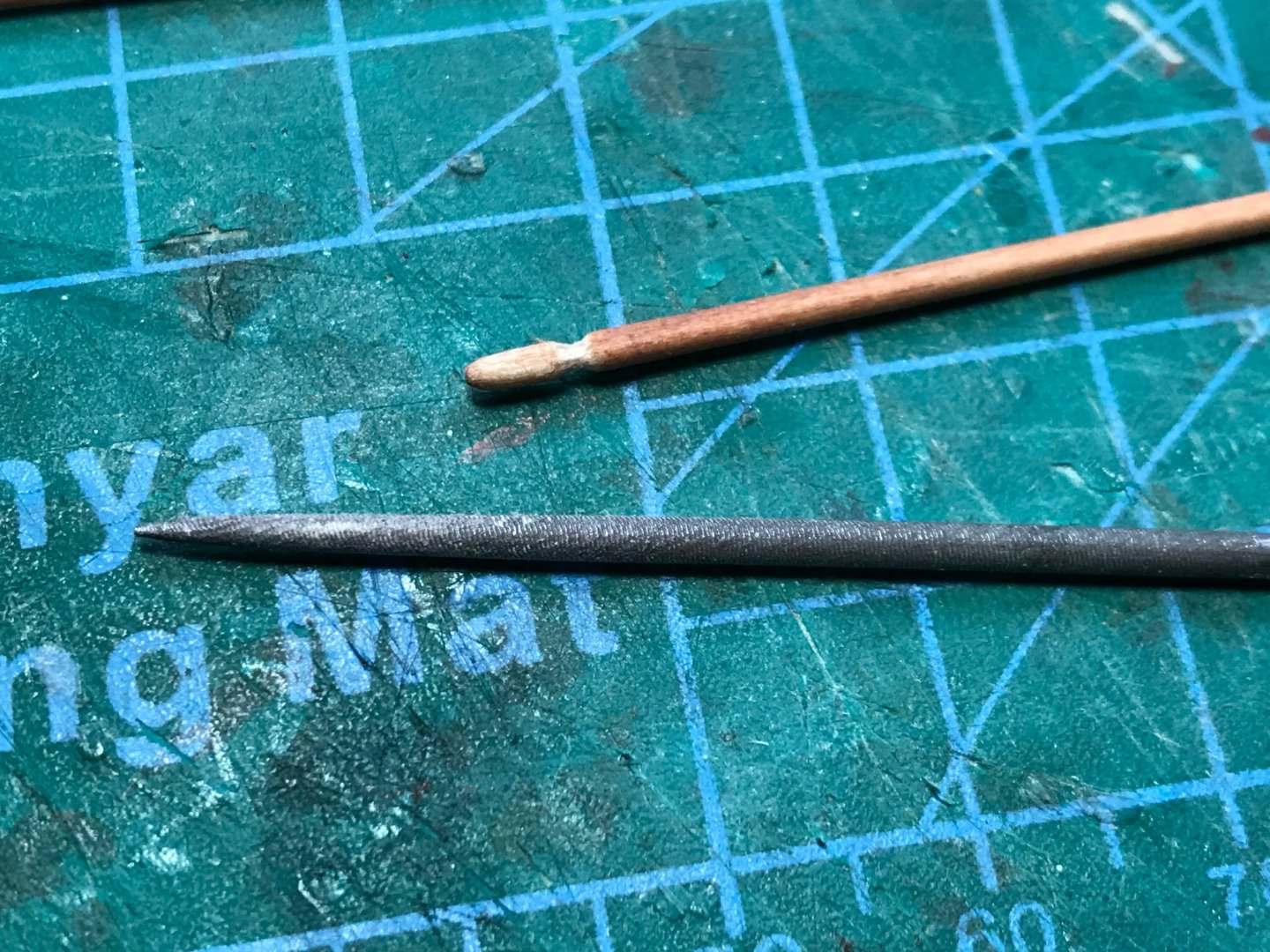
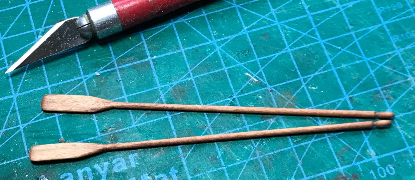
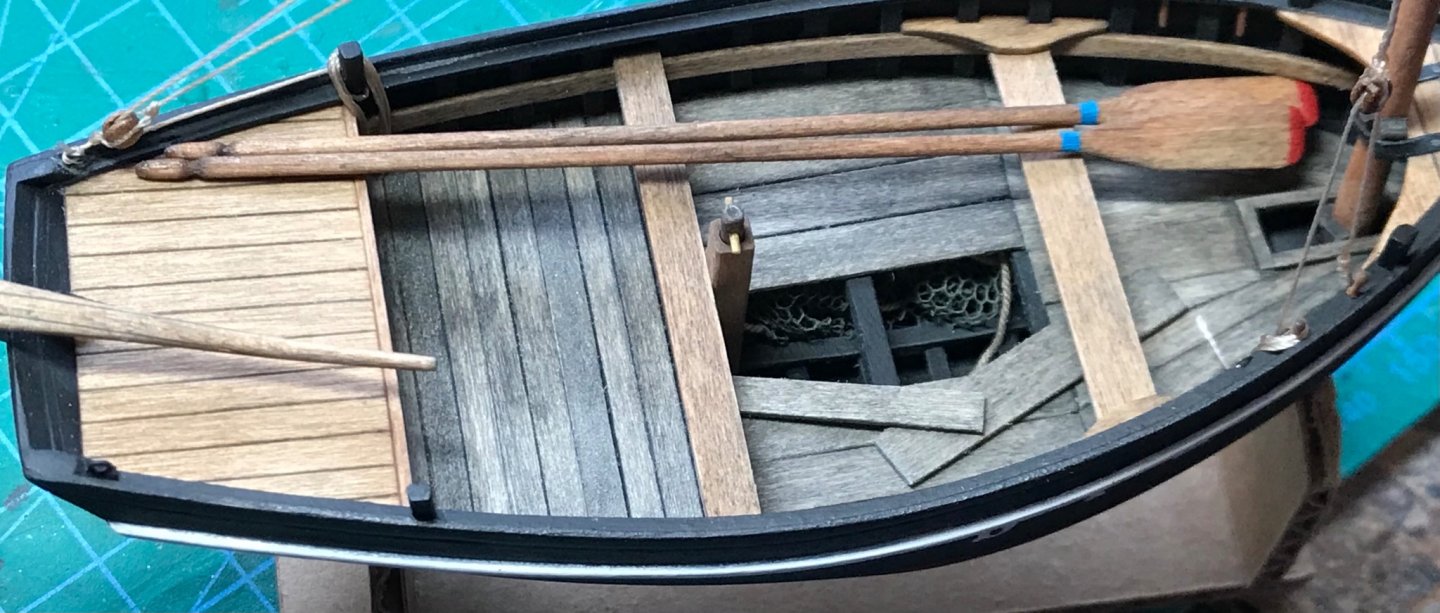
These little boats always seem to have oars lying about, so oars are a necessary feature for the model. My oar construction starts with three lengths of 1/16-inch basswood strip, cut into two pieces at 10mm and one piece at 100mm. The smaller strips are glued with PVA at one end of the long strip. After a few minutes of drying time, I start rounding the shaft by sanding down the corner edges. With the edges gone, you can twirl the oar in some folded-over sandpaper, creating the final rounded shape of the handle. Next, I start sanding down the edges of the paddle. Then, two corners of the paddle are filed to provide taper from the shaft to the paddle... ...and the paddle is sanded flatter and shaped. I use a home-made sanding block and/or sanding stick. Here is an almost-finished oar next to one which has not yet been shaped. Both oars are done and stained now. Decided to give them a little character with a handle end, using a round file... It takes me about 20 minutes per oar to get this far... A little weathering is added.... And finally, with a little color added for "feng shui," the oars are installed in the boat.


- 58 replies
-
- 15
-
-
Thanks! Must hurry. The weather is getting nice. Modeling season is almost over for me...
-
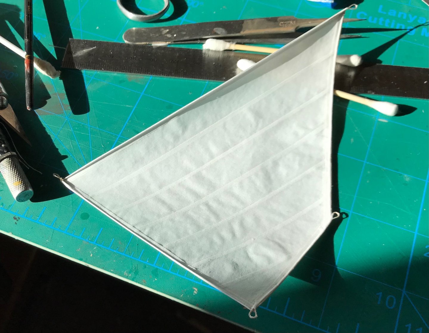
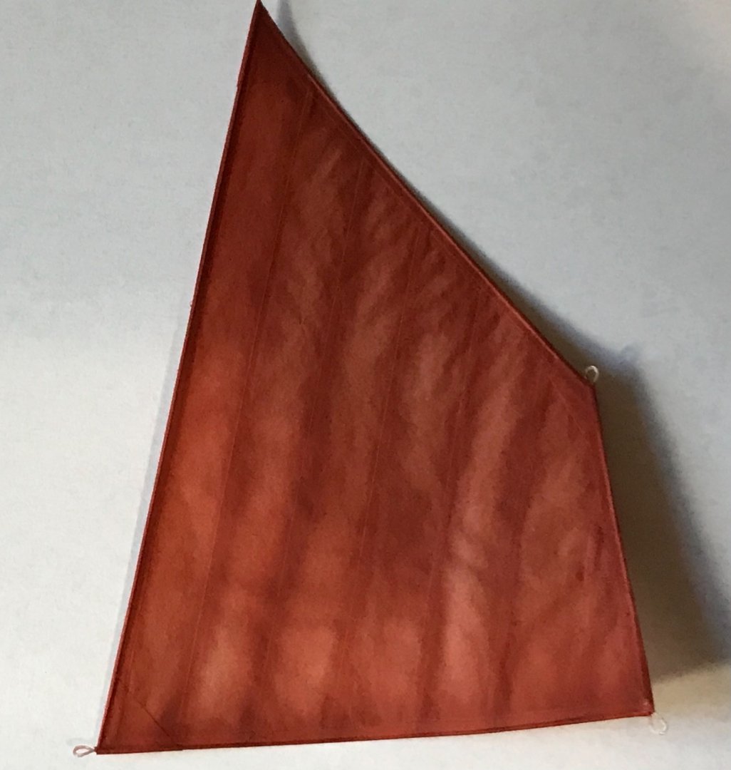
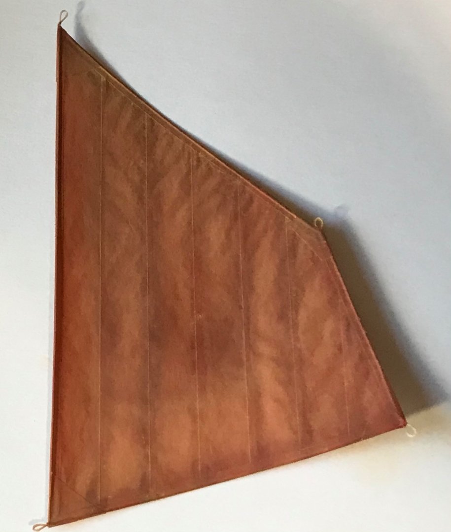
Building the sail today using paper, wire, thread, acrylic paint, and powdered paint pigments. Finished paper construction with wire embedded in the trim for bending the sails later... The painted sail (using Tamiya Acrylic model paint mixed from various colors)... After powdered yellow ochre paint pigment is rubbed in... I have posted before in more detail on my methodology for paper sail construction while building a Scottish Fifie (middle of page 2). https://modelshipworld.com/topic/27283-fifie-by-gbmodeler-finished-scale-148-typical-late-1800s-scottish-herring-drifter/?page=2
- 58 replies
-
- 11
-
-
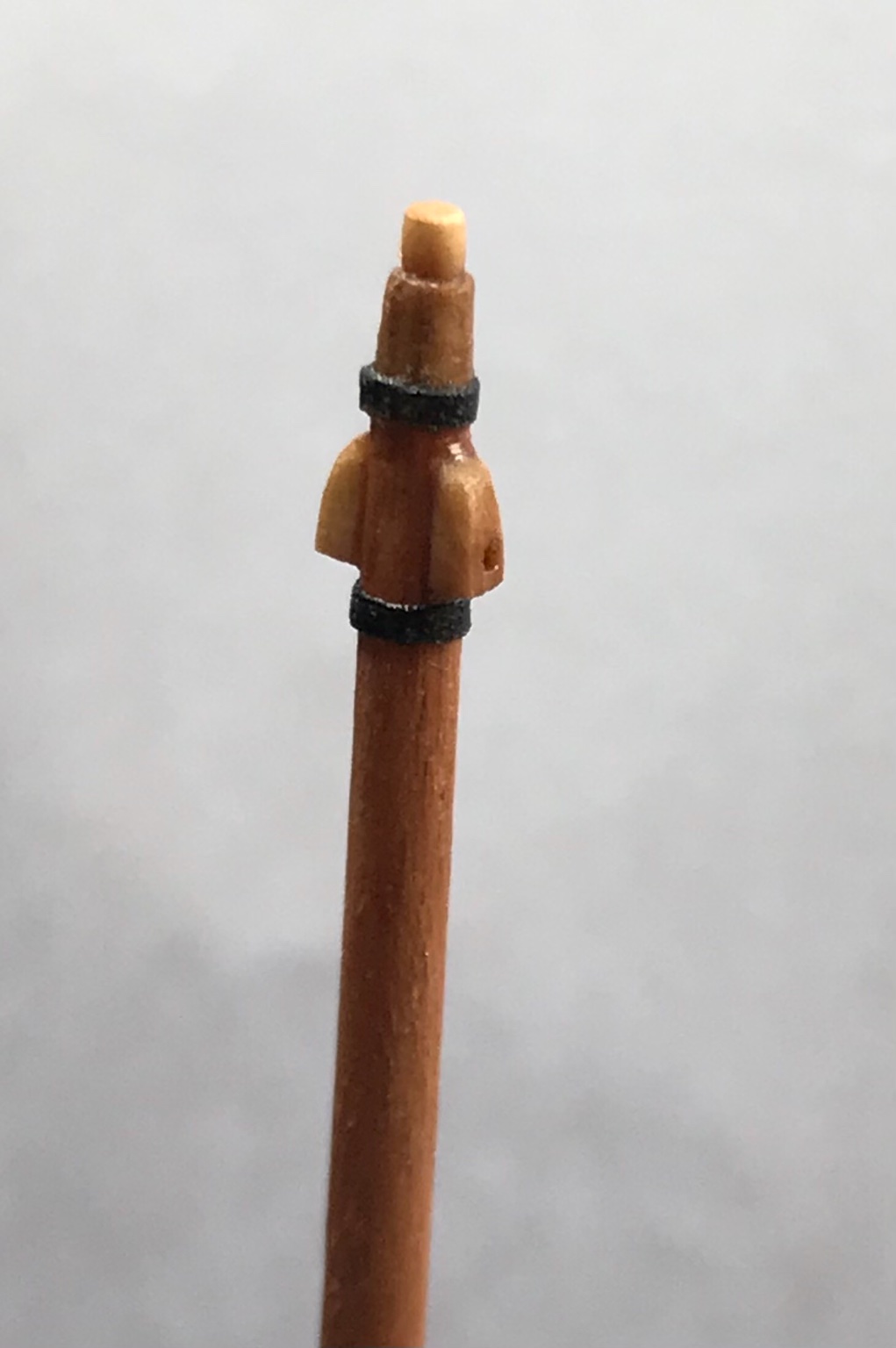
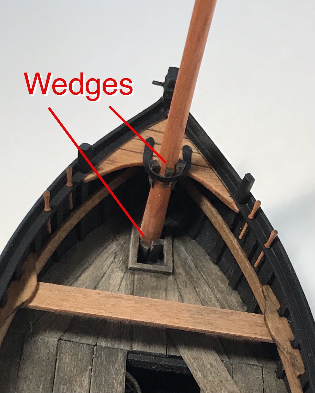
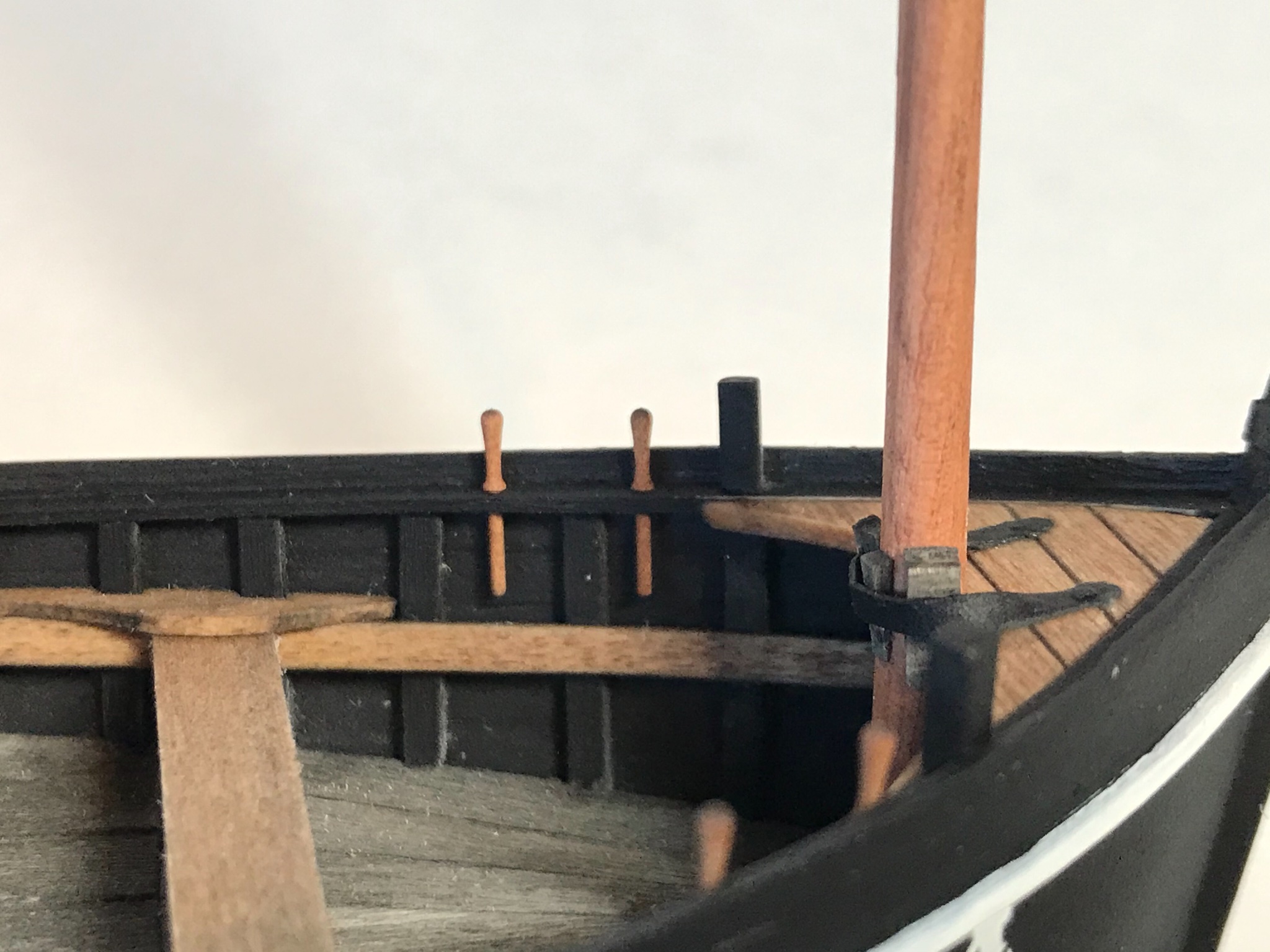
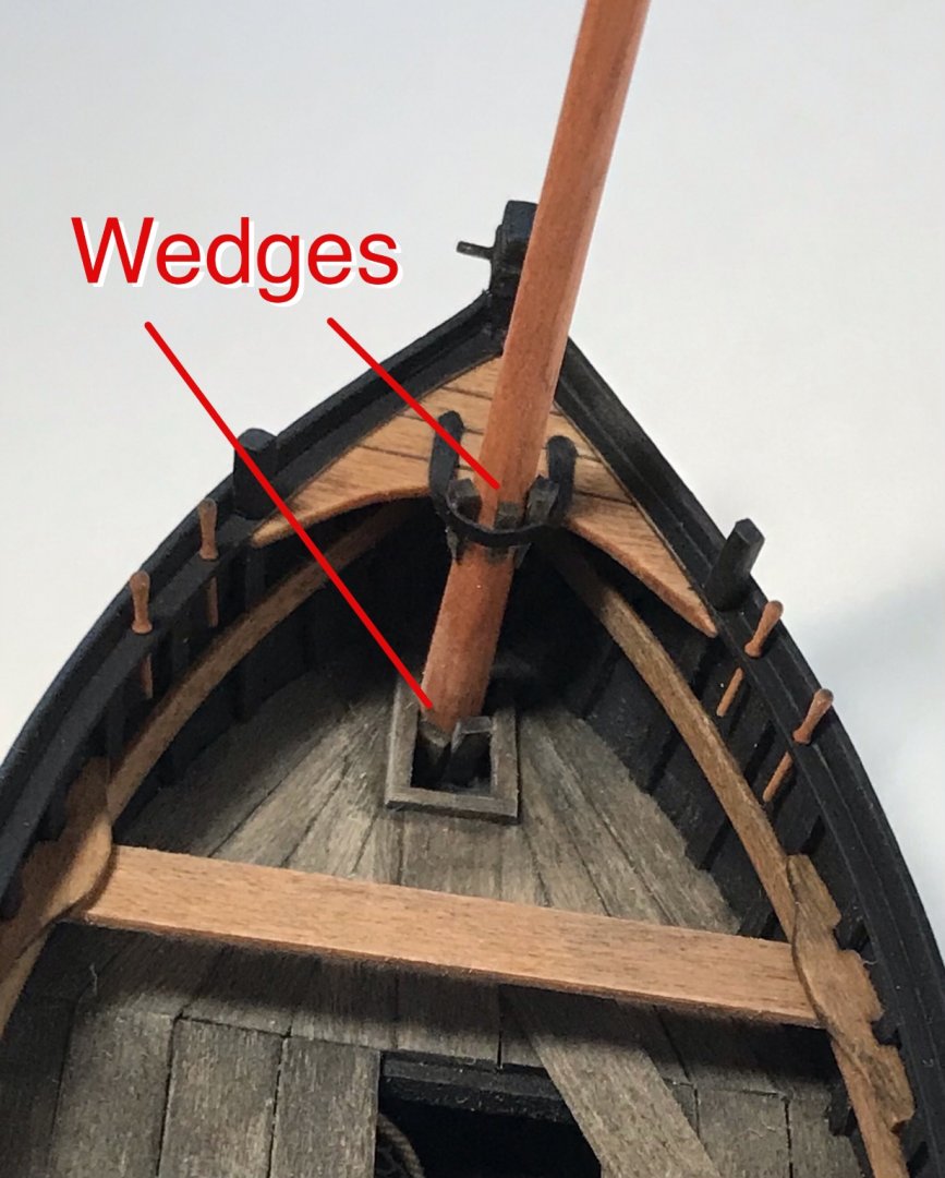
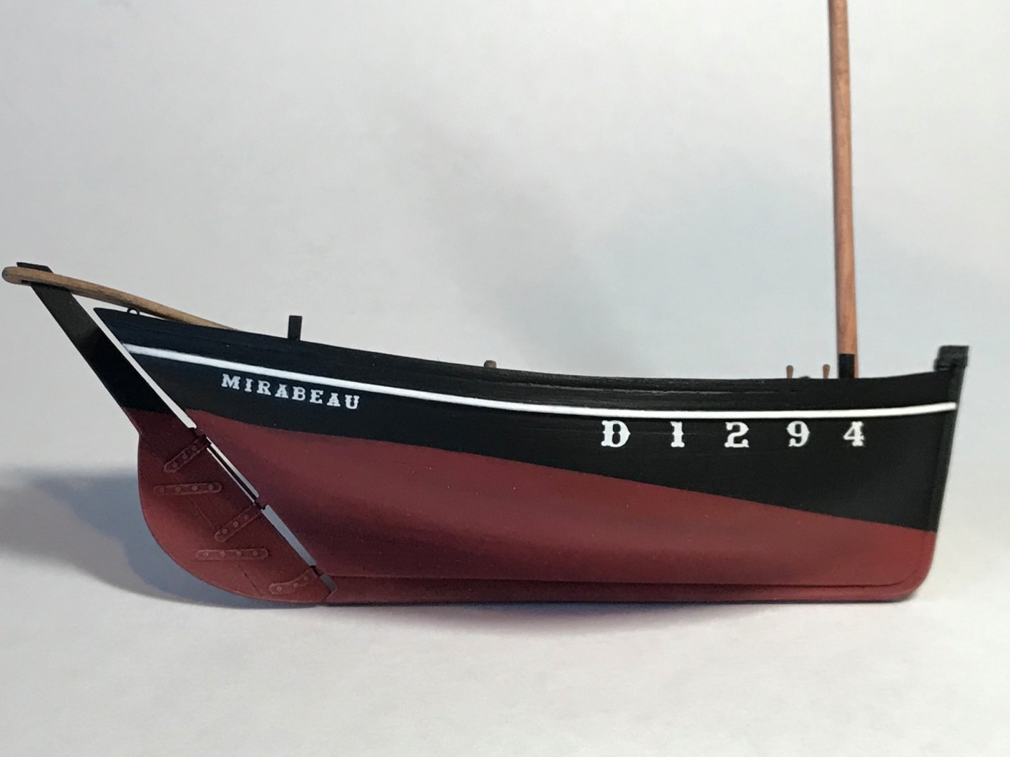
Been busy applying decals, painting trim, and building the mast. The mast was a wood dowel tapered slightly toward the top by sanding. Then bits and pieces were added to simulate the internal pulley at the top. Again, black construction paper was used to simulate metal bands. The mast was stepped and wedges installed as I have seen in photos of real boats. You will also notice the belaying pins from Falkonet. Further research indicates the boat I wanted to build (Petit Georges) was sloop rigged. I wanted the more typical lug rig, so I decided to change boats. This is now the "Mirabeau" from Douarnenez, 1906. Decals are water-slide, individual letters made by Microscale for model railroads. The font is called "ornate." You might notice a little "dry brushing" on the rudder....


- 58 replies
-
- 14
-
-
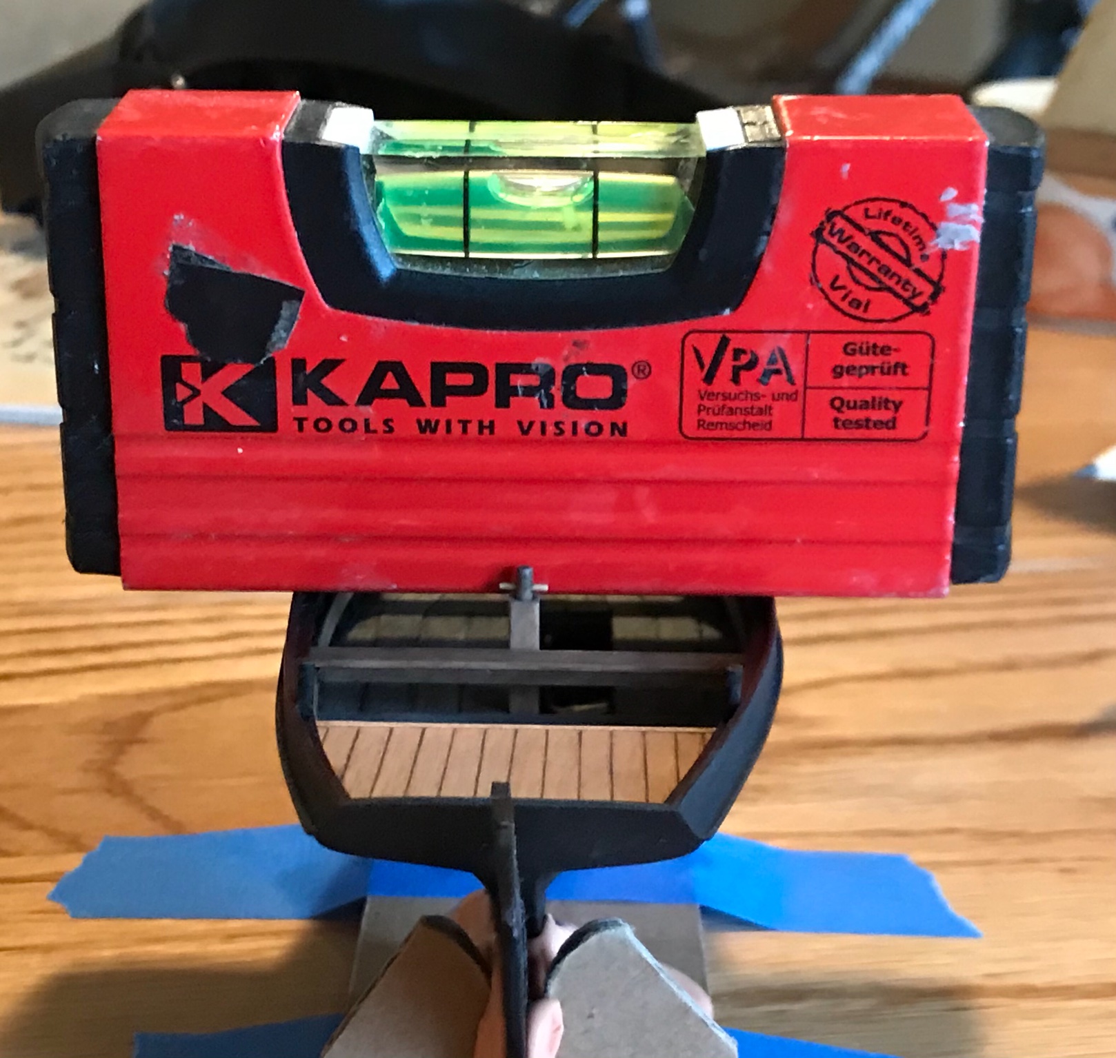
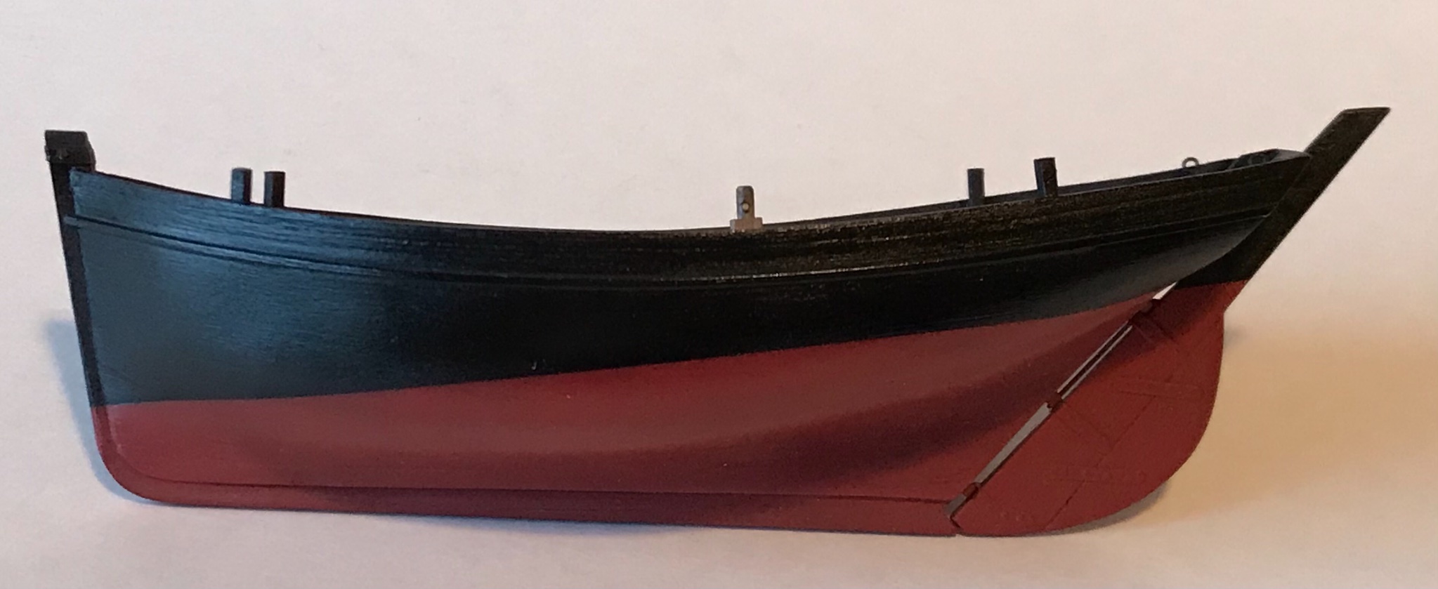
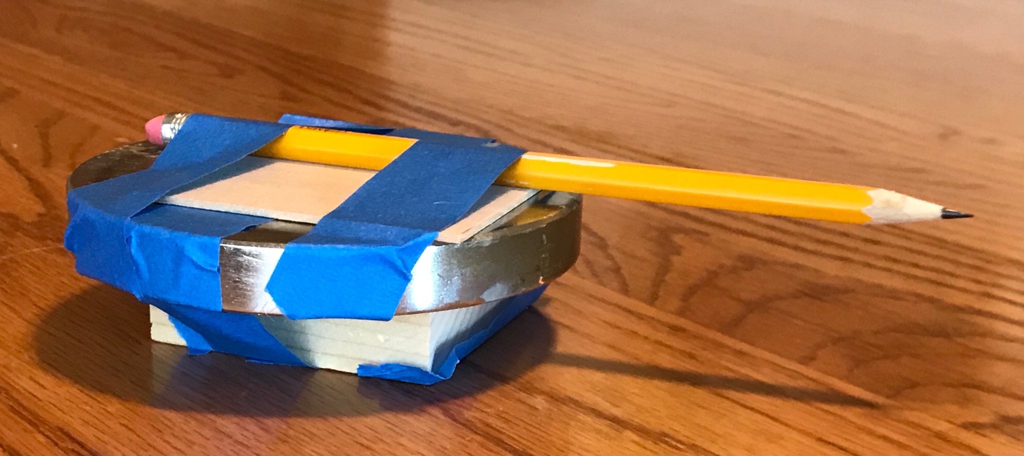
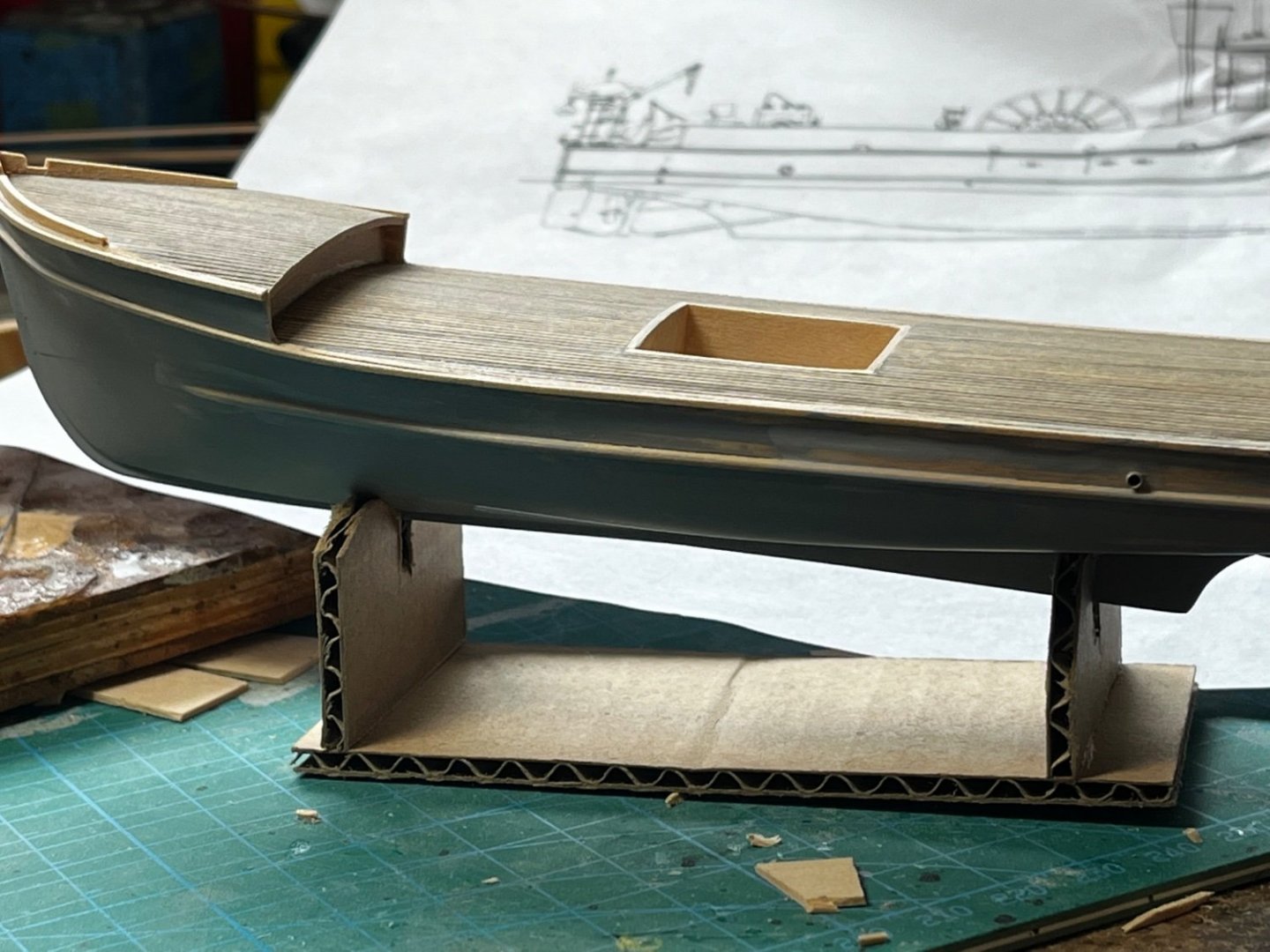
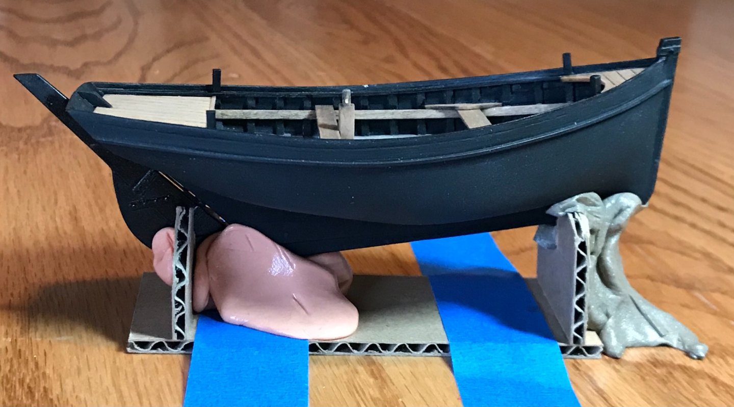
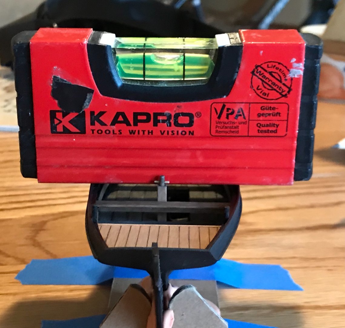
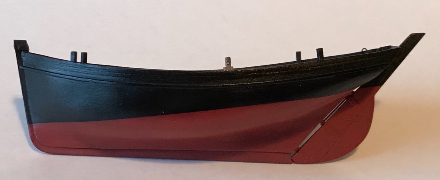
Painting the waterline comes next. I find this a nerve-wracking exercise but it does seem to get easier as I build more boats. I start by setting the model down on a flat surface, level to the waterline. This often takes props to get the waterline level. In this case, a little cardboard stand serves the purpose. The stand is taped to the table top and putty (Silly Putty) helps to "lock" the model in place. A small level keeps things even in the other direction. I use wood blocks for spacers to set the pencil at the correct height. In this case I added a weight from a dumbbell set. Modelers can't get too much exercise you know... The pencil line... Masking the upper hull... The final product, airbrushed on.

- 58 replies
-
- 11
-
-
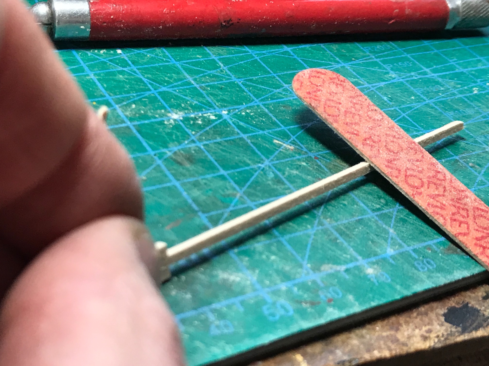
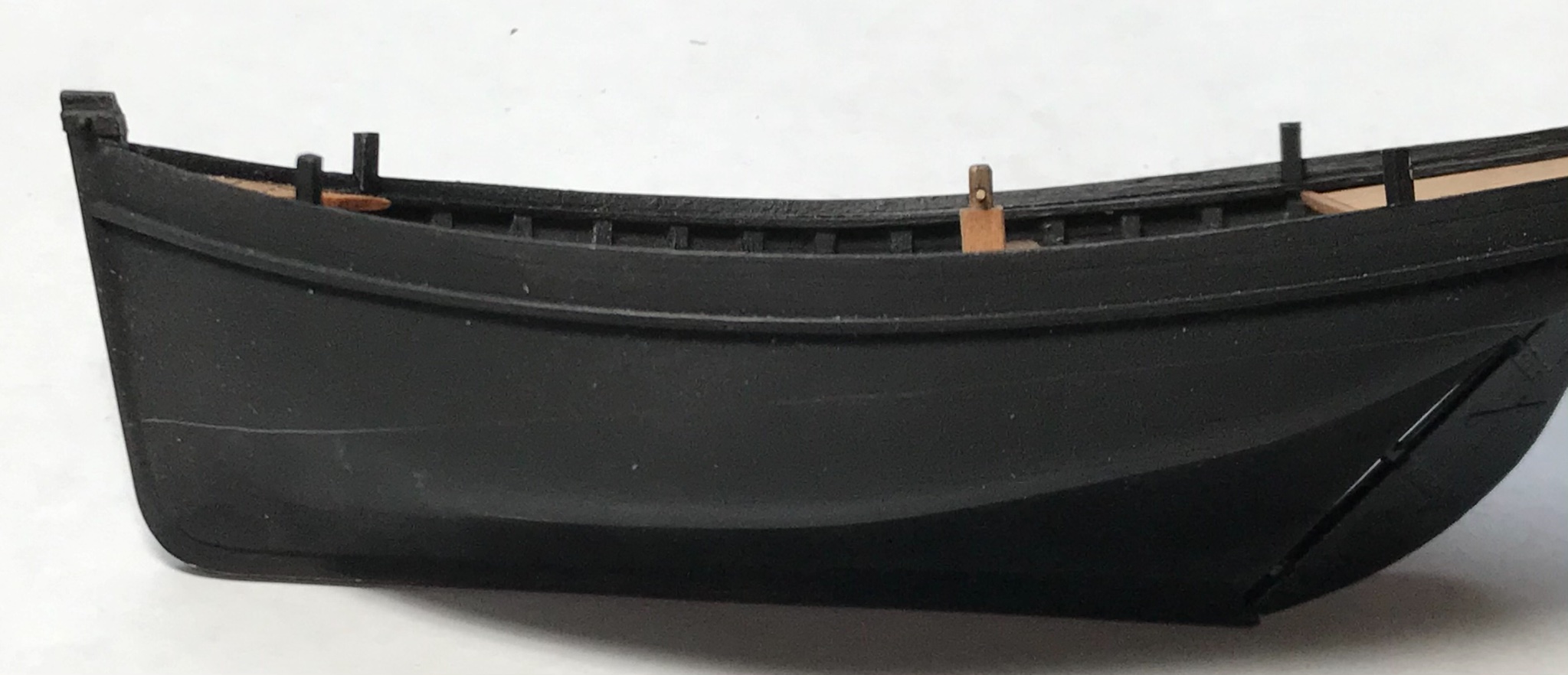
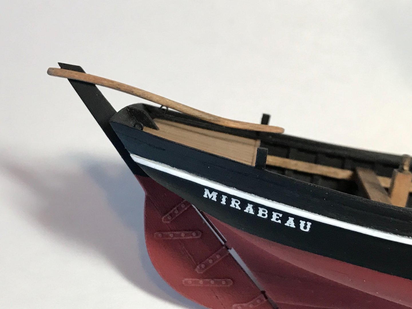
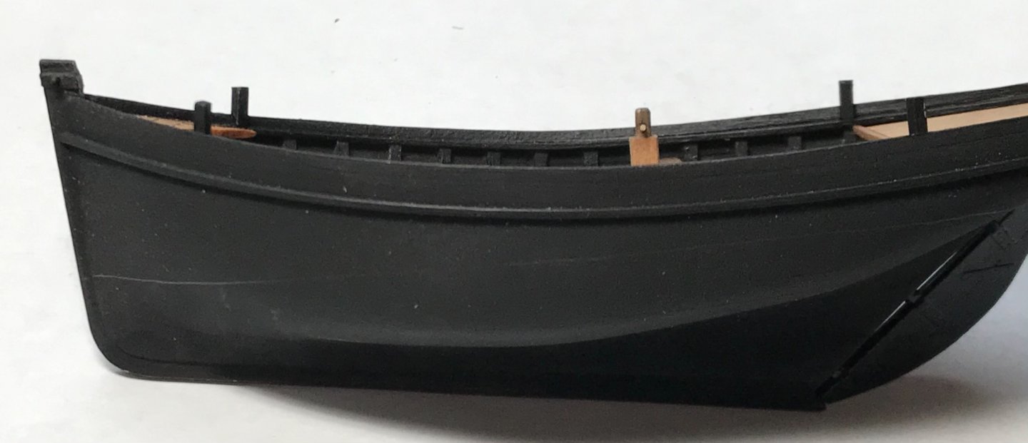
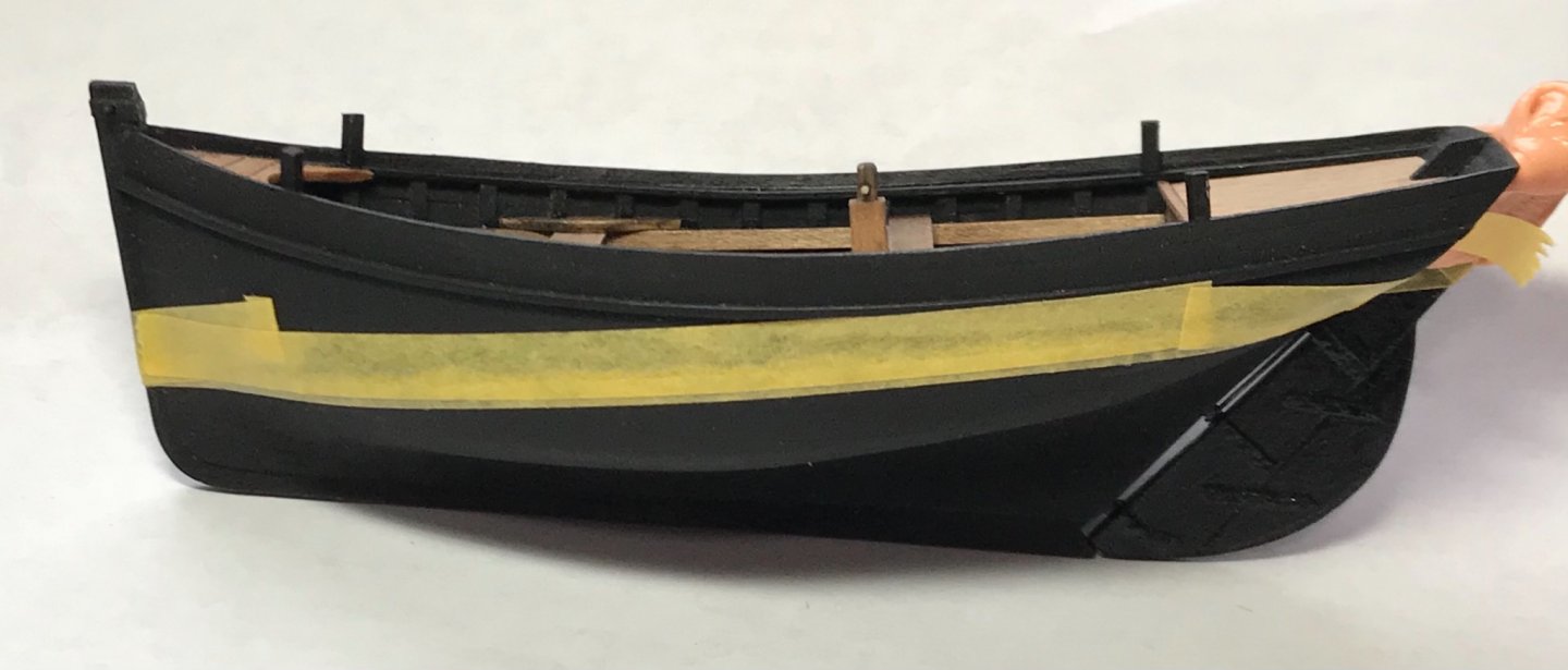
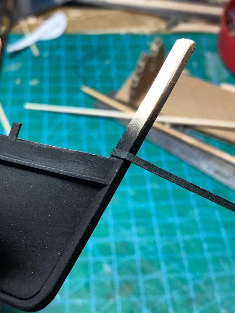
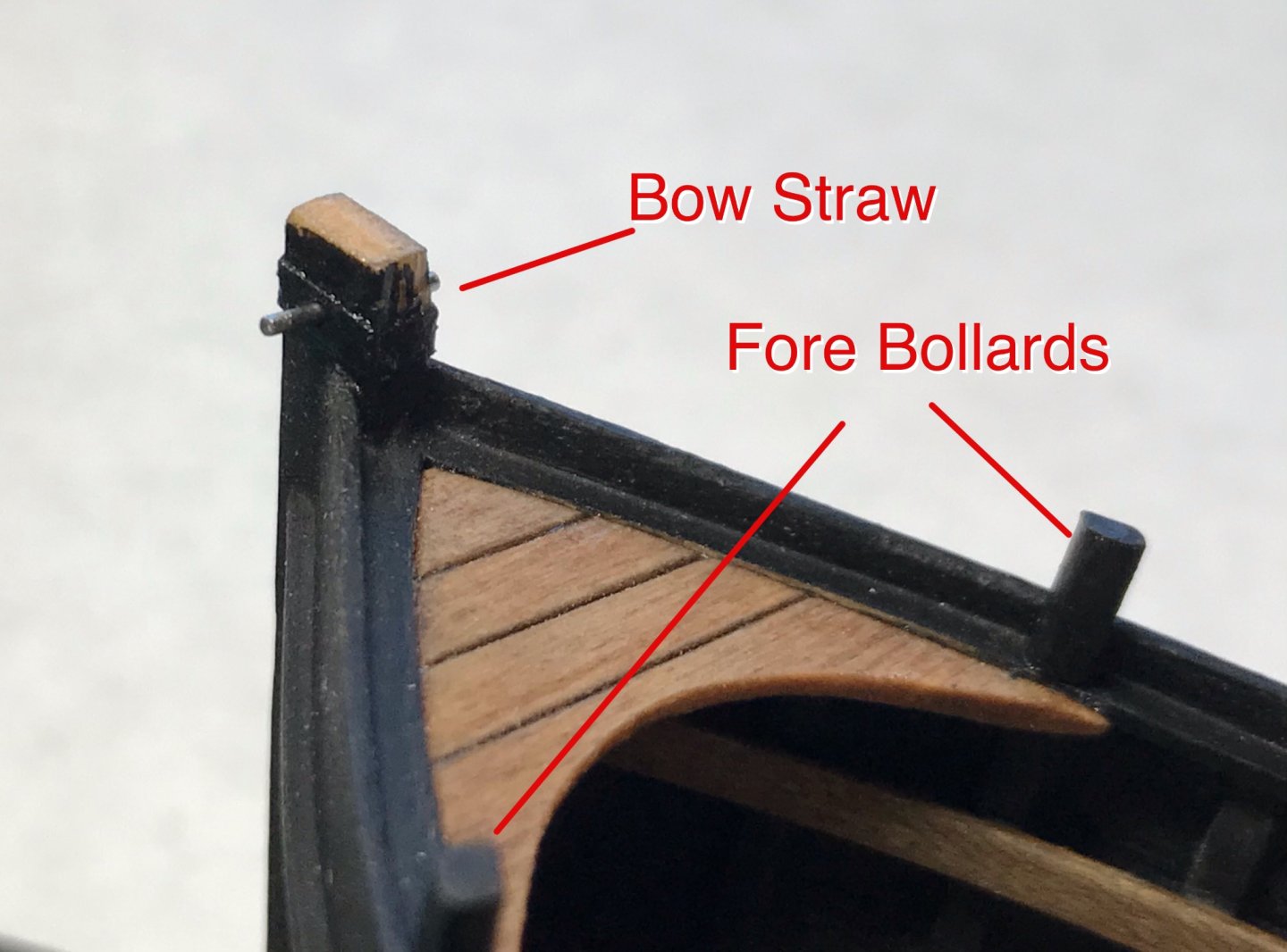
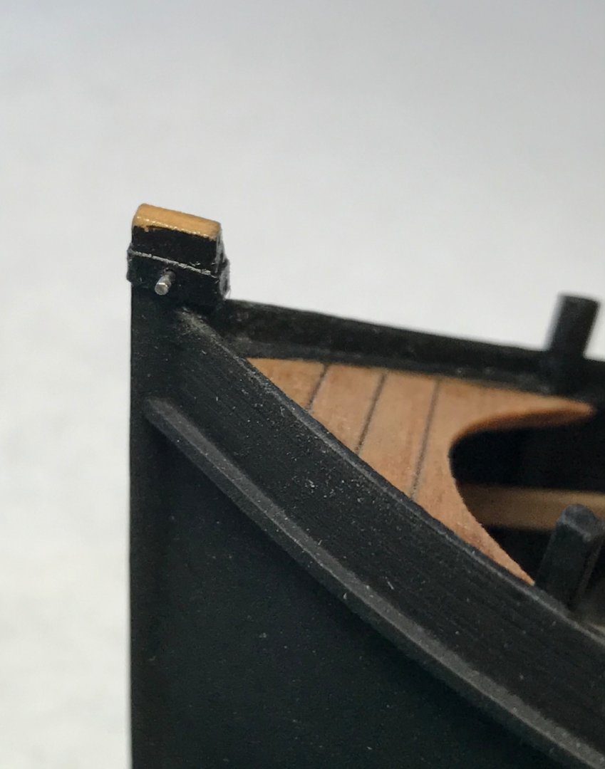
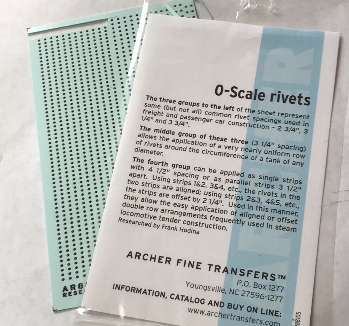
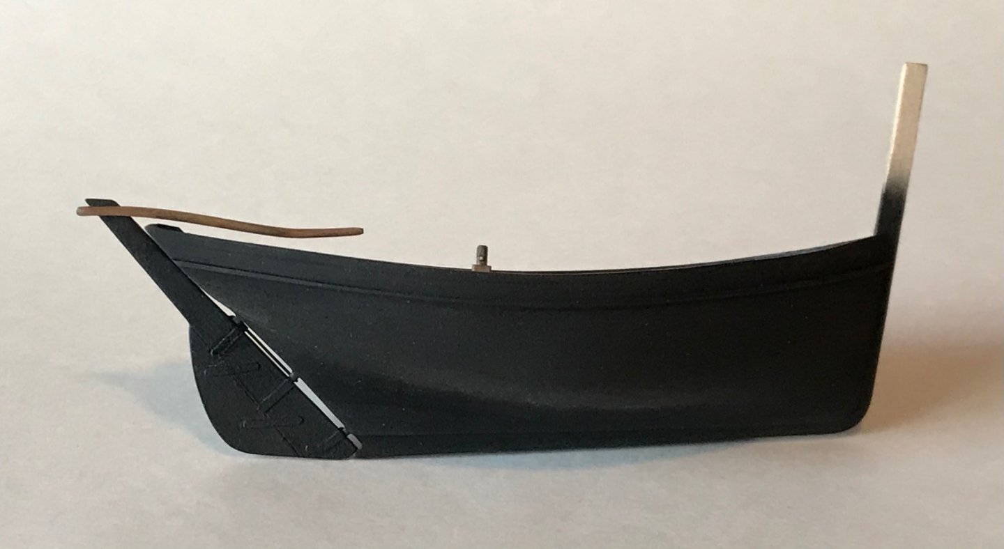
Adding little (but important) details now. The first is the "paille d'etrave" which translates to "bow straw." The clew of the sail was attached to this metal rod that ran through the top of the stem post. It was reinforced with a metal band. I substituted construction paper for the metal band, but the rod is steel piano wire😃. You can also see I added bollards: two fore and two aft. The bollards are placed above false frames to simulate extended timberheads... After coating the rudder with an enamel gloss coat, I set about adding the rivet decals. Here is what I used... Here's the (almost) final result with another layer of gloss coat to protect and seal the decals.
-
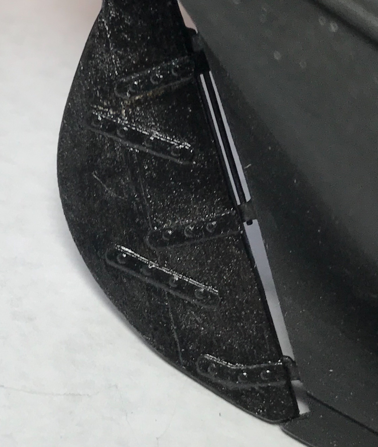
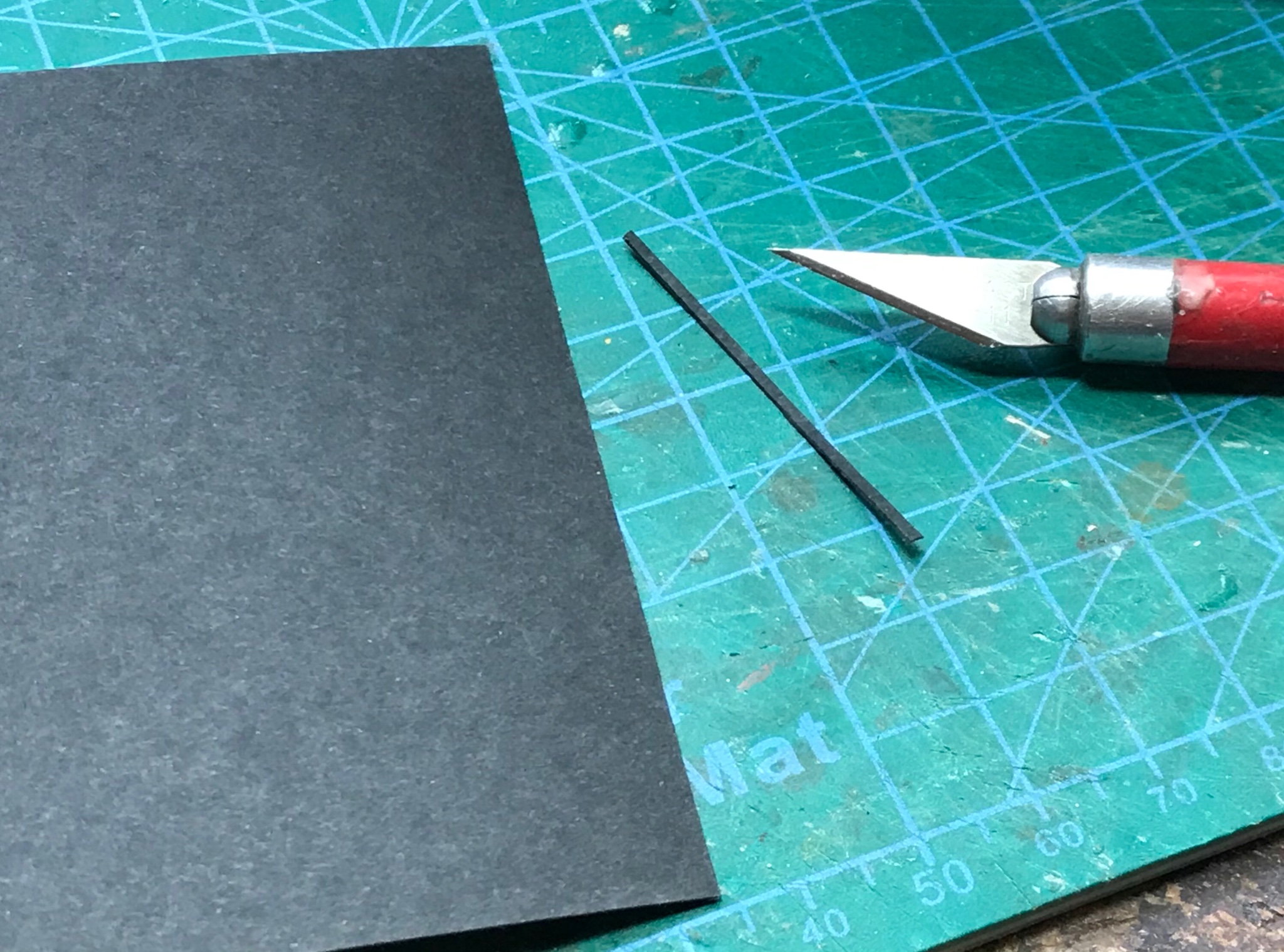
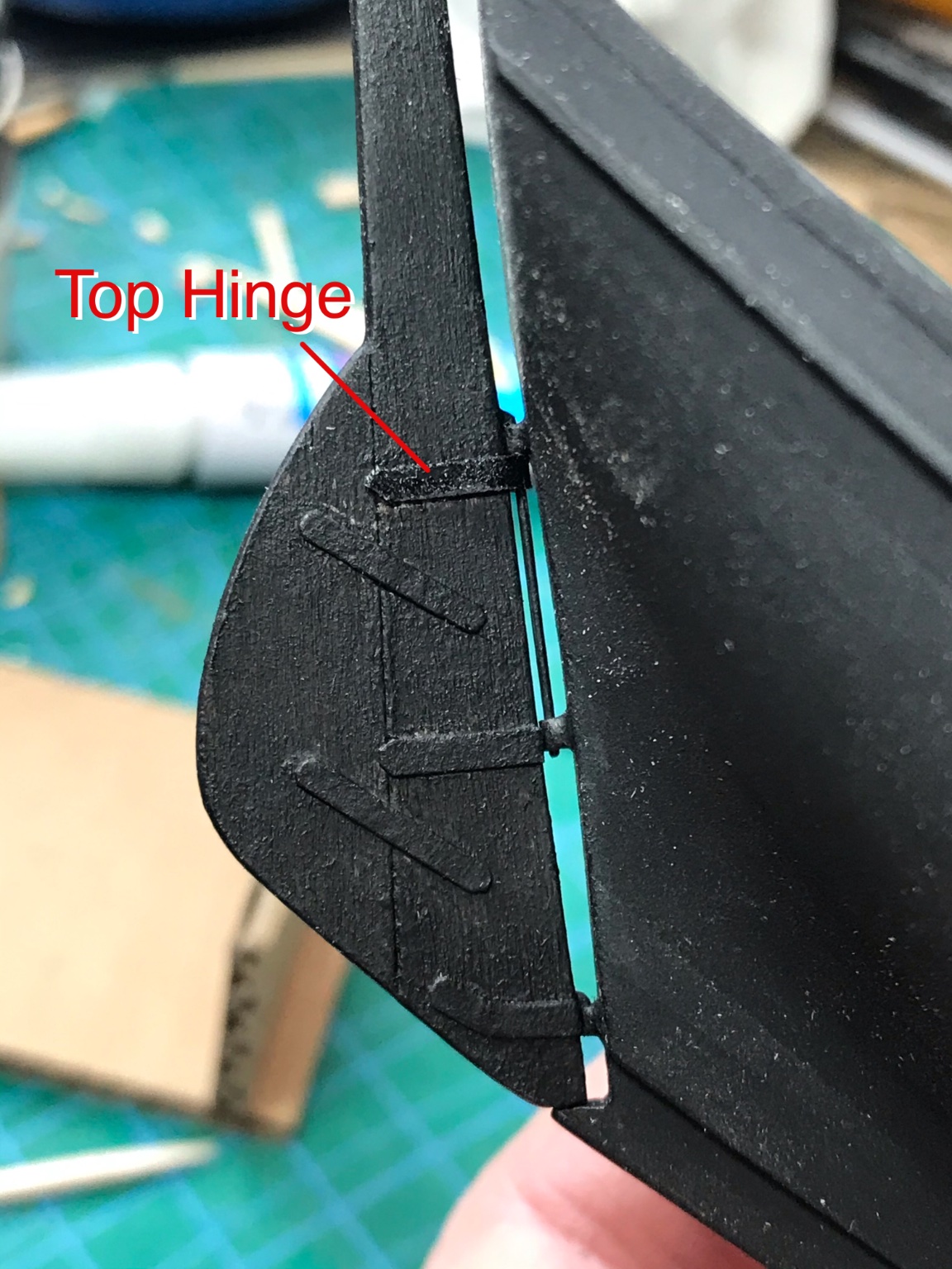
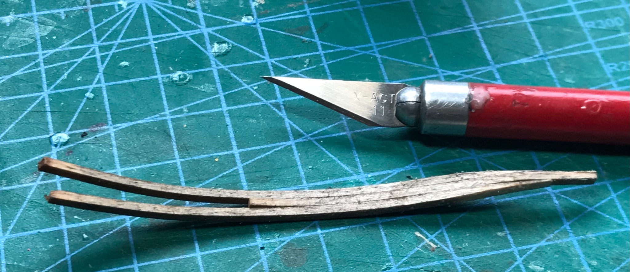
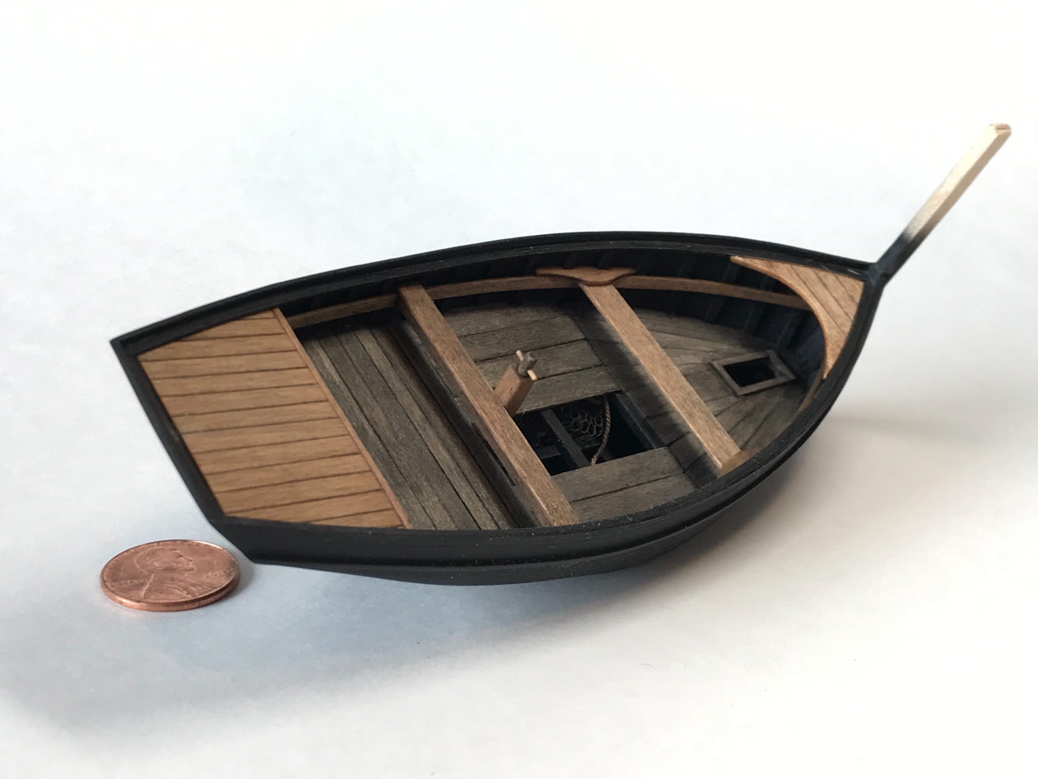
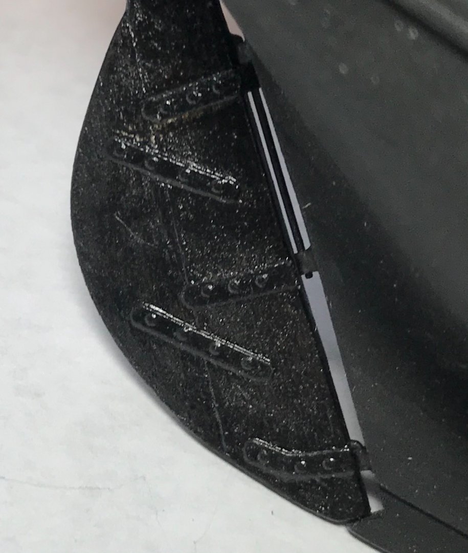
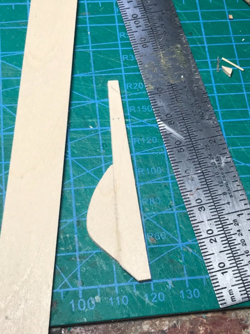
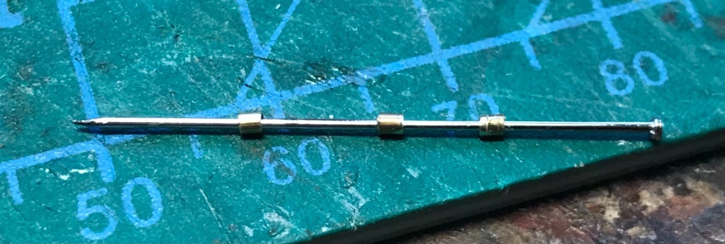
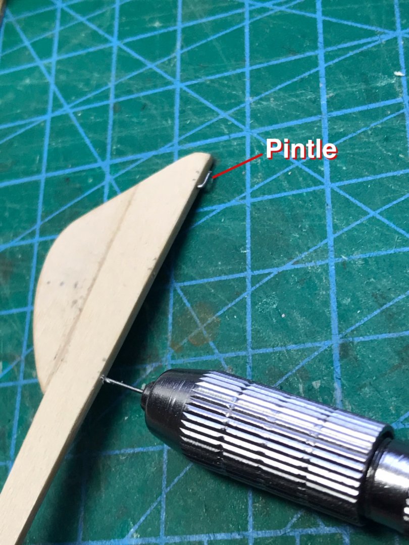
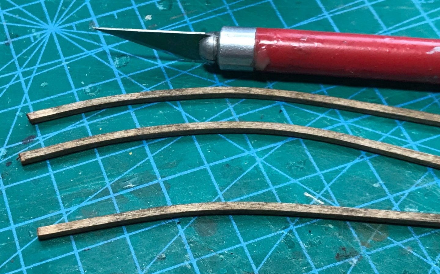
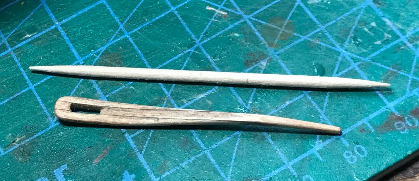
Yesterday was "rudder and tiller" day. The rudder started life as a sheet of 1/16" thick basswood. Parts were cut and shaped based on drawings and glued together with PVA (white Elmers) glue. Gudgeons were prepared from short sections of brass tube. The tube cut nicely by lightly rolling it under the knife blade. A pin was used to provide alignment as the little tubes were attached to the hull with gel CA glue. The gel variety sets slower so adjustments can be made, but you still have to work quickly... Pintles were installed into the rudder using a pin vice and piano wire, pre bent at a 45-degree angle. Braces and hinges were fabricated from thick construction paper and attached with PVA glue. Here you can see the (almost) final product. The top pintle is long, and goes through the top two gudgeons (as per photos I saw of real boats). You will notice that the top hinge is shiny. This piece of construction paper was applied after the rudder was slid into place and has been reinforced with a coat of CA glue to give it added strength. Because of it's position, it "locks" the rudder in place (i.e. the pintles can not lift up or unship from the gudgeons). All this adds up to working rudder! I plan to add rivets to all he paper parts using 3-dimensional rivet decals. The tiller started life as 1/16" basswood strips. These were bent by soaking briefly (a couple of minutes in water) and ironing with a clothes iron around a curved former. They are pre-stained so glue doesn't block the application of stain later... Here the strips are glued together and shaping beings (mainly with a sanding block). The final product is tiny, compared to a common toothpick... Now we can steer!


- 58 replies
-
- 12
-
-
I really appreciate your observations gsdpic! Besides the chance to research, gain experience and improve one's skills, I really enjoy the simpler models because they can be finished much more quickly. The sense of accomplishment provides encouragement for bigger projects down the road!
-
Thanks for the comments everybody. You all know how to encourage someone!
-
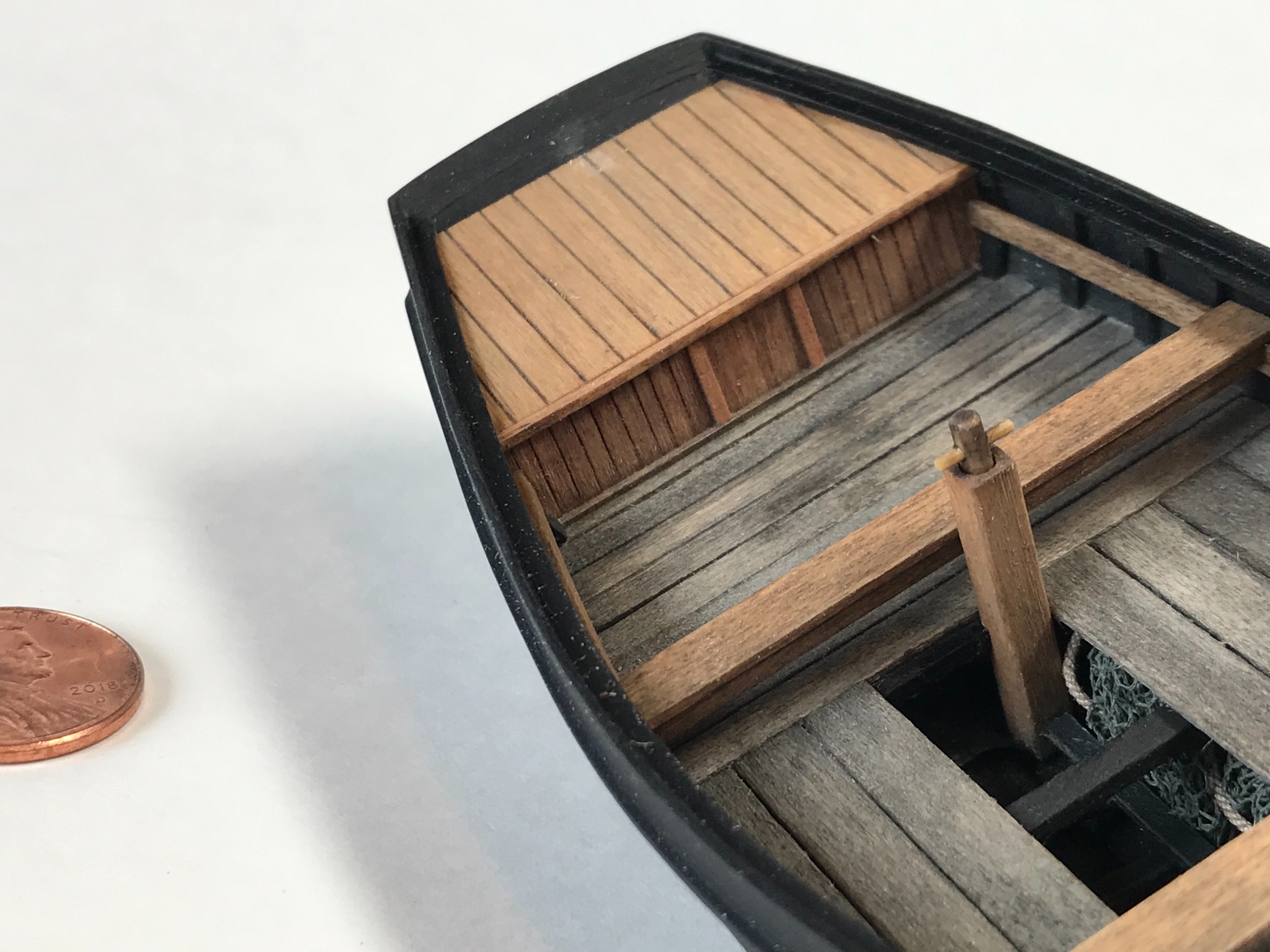
The bilge pump was made from a heavy strip of basswood (1/8" square) with a hole drilled in the top to accommodate the pump rod (toothpick). The handle is a sliver of bamboo tooled into a small dowel, inserted in a small hole drilled through the toothpick.

- 58 replies
-
- 14
-
-
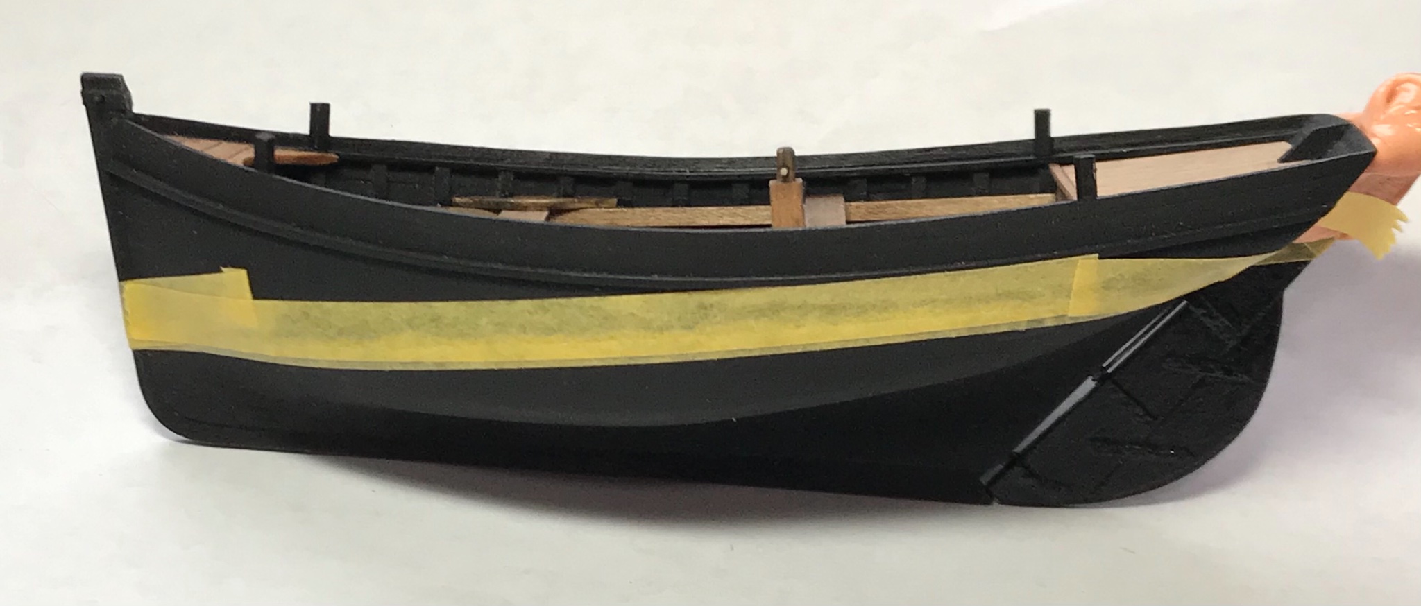
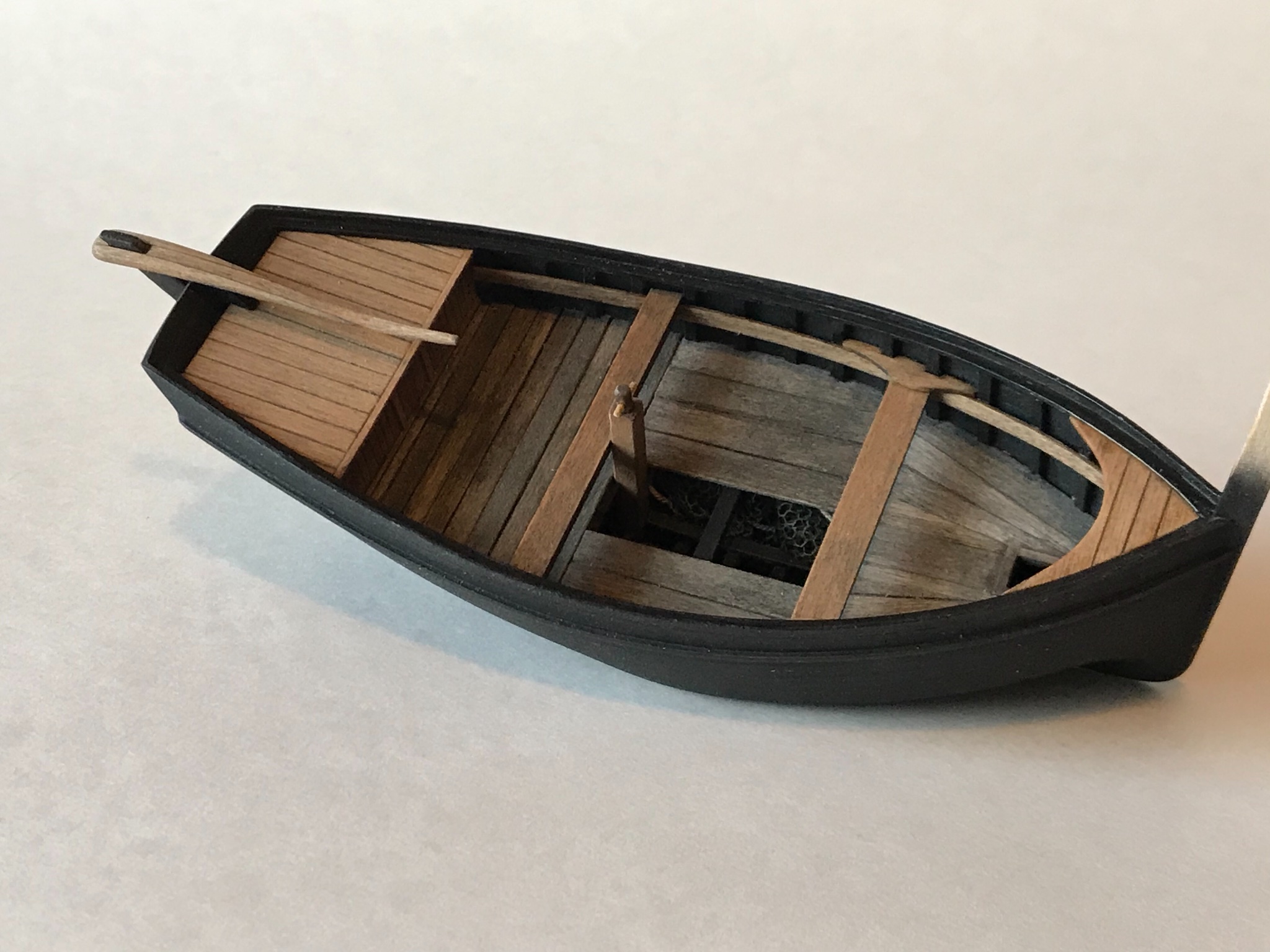
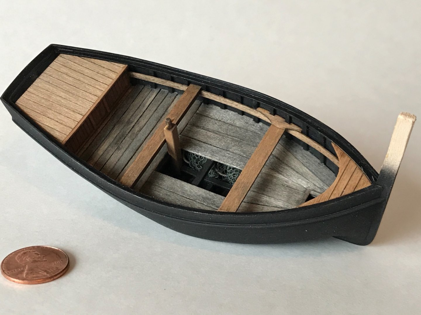
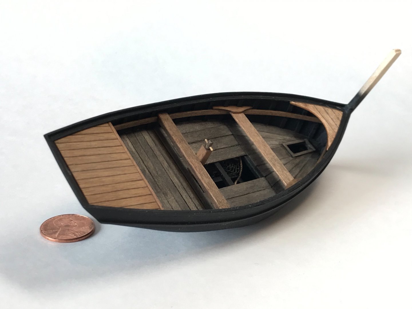
Installed the short decks, thwarts, bilge pump, and an old net under the floor... The fore thwart braces were made from some scrap wood.

- 58 replies
-
- 11
-
-
This looks fun! I'm in.