mikiek
-
Posts
2,276 -
Joined
-
Last visited
Content Type
Profiles
Forums
Gallery
Events
Everything posted by mikiek
-
Bolt Heads on Brass Strips
mikiek replied to mikiek's topic in Metal Work, Soldering and Metal Fittings
Richard - time will tell. My guess is that steel is pretty good. In the case of the rivets the tip of the punch has no sharp ends/edges to dull. I have seen a few reviews on the regular punch and the hex nut punch (nothing on the rivets) and people were pretty happy. Of course how much hard material and how much soft material they were going thru was not real clear. My tests so far were using brass at the high end of the recommended width - probably why it took several whacks with the hammer to get the rivet. I have some thinner brass on order so I'll be interested to see if that takes a few less blows. The biggest issue I am having is gluing the smaller rivets to a surface and then blackening them. I was using CA and even applying with a straight pin, the glue spot is too big and that spot doesn't blacken. This weekend I will punch a few, blacken them and then glue them to see if that is a realistic option. Several of the rivet sizes are smaller than a pinhead so I am skeptical about putting them thru the blackening first (and finding them afterwards), but we'll see. -
Cutting Boxwood
mikiek replied to mikiek's topic in Building, Framing, Planking and plating a ships hull and deck
I have most of the tools mentioned. However, I'll be cutting planks for the deck - not a single long one per strake but "20 footers" . That's a lot of cutting. I was hoping to avoid having to cut each one individually. Thinking back, my question may have been more of a gripe. It was taking 20-30 seconds to hand cut a plank. I'll probably give the power miter saw a spin. My impatience showing through -
Man - you are quick at those things! Thanks Don.....
- 843 replies
-
- 3
-

-
- niagara
- model shipways
- (and 2 more)
-
I just got some replacement planks for my kit. They are 1/16x3/32 boxwood - replacing basswood. I can't cut these guys with an Exacto - even with a new blade. Is there something else to hand cut or am I going to have to use a power saw?
-
I think I'll keep the pix for posterity. So shoulder is the term for the sharp edges of the square section? That's what I was calling the corner. I see how those edges extend out over the octagon. That's what I'm getting as well, except my square section is next to the round. For curiosities sake, if the taper went the other way and the square was the thinnest section instead of the fattest, would those edges still overhang? Thanks for taking the time Don. Sorry about the mess
- 843 replies
-
- 2
-
-
- niagara
- model shipways
- (and 2 more)
-
Bolt Heads on Brass Strips
mikiek replied to mikiek's topic in Metal Work, Soldering and Metal Fittings
Mark - the punches are 2 parts. The pin shaped part that pierces the material is probably some sort of steel. That fits into a cylinder, which is the part you strike, and that is aluminum. Grant - putting something on top of the punch is definitely a possibility Richard (rtropp) - here's the link. The RP Toolz products are about half way down the page Richard (Altduck) - pressing thru styrene would be easy. Personally I'm more interested in brass. It took about 5-6 whacks of the hammer to get thru a brass strip that is about 0,3 - 0,4 thick. I do have some thinner brass sheets on order. Pressing might be easier then. -
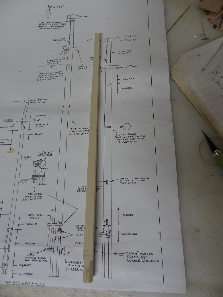
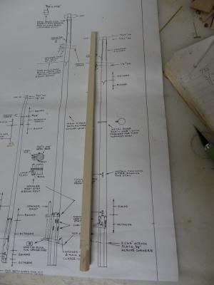
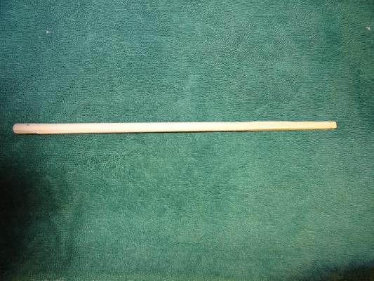
Don - I'll take all the help I can get. Any pix would be great What I did for the mast: Tapered a square strip to meet dimensions on plan. Marked off the top section (square) Carved the rest of the strip to an octagon shape (still tapered) Marked off the bottom section (octagon) Sanded everything in between to round Where I'm stuck is: If you look at the mast from the top down and follow a flat side of the square, it looks great all the way to the bottom. The centerline of the square transitions flush into the round and even into the octagon. Now give the mast a 1/8 turn so you are looking down a corner of the square. Draw a line down that corner and when it gets to the round section you'll see that the corner is raised slightly above the round section. This is the same on each corner - at least I'm consistent. Maybe that's how it is supposed to be, but it looks odd to me.
- 843 replies
-
- 3
-
-
- niagara
- model shipways
- (and 2 more)
-
Bolt Heads on Brass Strips
mikiek replied to mikiek's topic in Metal Work, Soldering and Metal Fittings
I wondered about that Mark. Would I still get enough of a strike with the rubber insulating the blow. Also the size thing, the supplied hammer is about 3" long. I'll search around on the web and see if I can find something similar. For sure I am going to have to do something. -
I have pretty much finished the foremast. Shaped and rounded except for one thing. How do you transition from the rounded section to the square section? The corners of the square extend beyond the circumference of the round section. That looks kind of funky. Oh yes, I did update my log tonight.

-
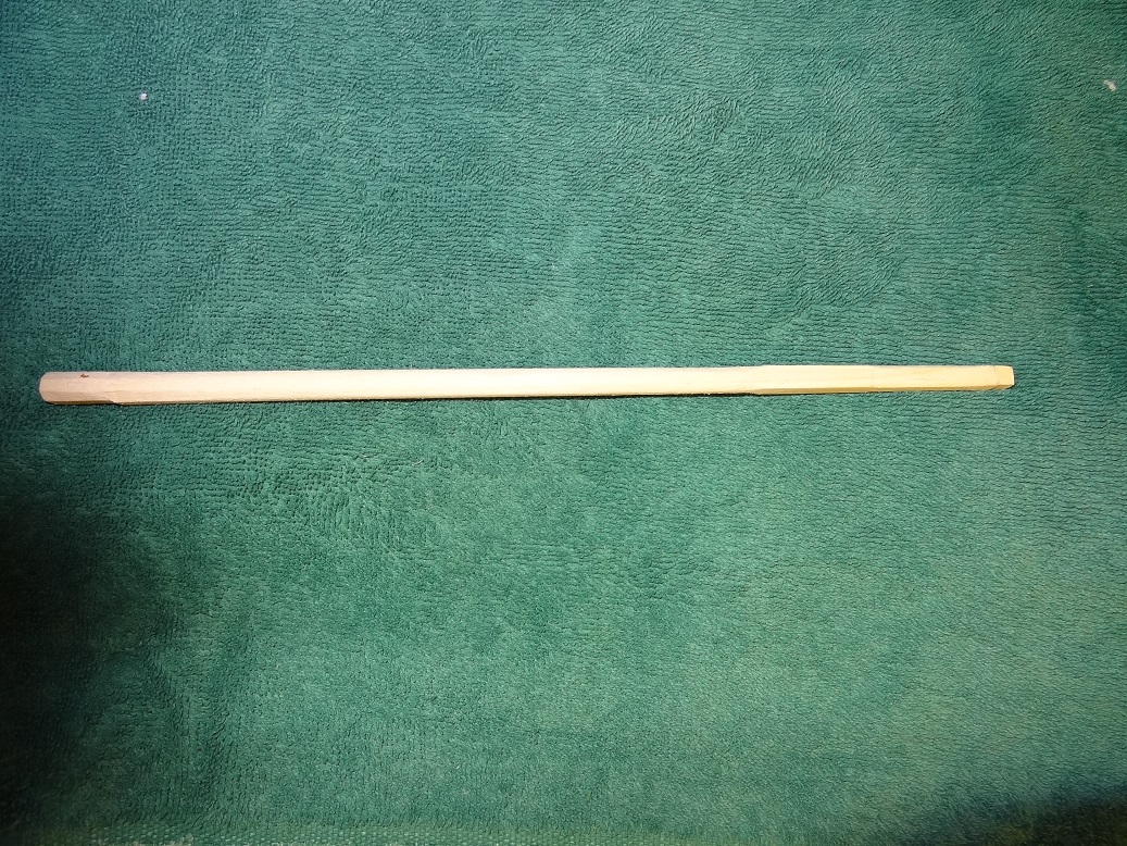
Time to check in. A lot has been going on. As I may have mentioned before, I am taking a break from the big boat and trying my hand at some of the other parts & pieces. I have started the yawl. The layers are glued and the hull has been shaped inside and out. I want to really detail this guy (and the other 2) so I'm looking at the frame pieces, floor boards, etc. I'm struggling with bending the frame pieces to fit inside the hull. Here is the discussion so far. Not sure where I will end up. A previous post shows a little of the work on the carronades. Those are fun to make, but just a few at a time. I got to thinking about the mast last week. I am afraid I will forget to add some bracing to the mast slots on the keel and end up decking her out. So the brought up a lot of questions regarding the mast foot, shaping the mast, etc. This discussion has set my off in the right direction. Another suggestion was to start with a square strip rather then the kit supplied dowel. Working off that, I cut a strip from some scrap birch, tapered that down then began carving and sanding. I've been using Tamiya sanding sponge for the last bit of rounding. I really like that product! It has come out pretty well (see pix below) but I am stuck on one thing. The base of the mast is octagonal, then round and finally square. I can't figure out the transition from round to square. The flat sides of the square are flush with the round surface but the corners of the square extend beyond the round surface. There's a couple of pix showing that. One of the things I have been itching to start is the deck. Following a Niagara practicum, I am going to build it separately and then drop it in once completed. The bulwarks on Niagara leave plenty of room to do this. I have to say after working the bulwarks I have not been overly impressed with the basswood planking from the kit. So I ended up ordering replacement planking and mast stock (boxwood) from Crown Timber. That all arrived today, so I can get to thinking about the deck now. I will say it is very nice stuff. I may get Jason to replace the entire stock of my next build.

- 843 replies
-
- 4
-
-
- niagara
- model shipways
- (and 2 more)
-
Don, jct - thanks for the encouragement and welcome aboard. Don - that pitting was my overindulgence with the blackening juice, but I also like that look. jct - I realized a few weeks back that while working on the starboard bulwark, I have broken every timberhead on the port side. Some more than once. All fixed with the runny CA glue. I'm not looking forward to sanding those!
- 843 replies
-
- 3
-
-
- niagara
- model shipways
- (and 2 more)
-
Bolt Heads on Brass Strips
mikiek replied to mikiek's topic in Metal Work, Soldering and Metal Fittings
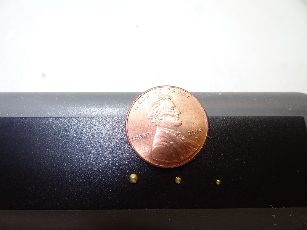
I broke down and ordered the RP Toolz rivet punch set. It arrived today. VERY COOL! Just like most punch sets but these cut out a half domed shape piece. Looks a lot like a carriage bolt head. I don't know if something like that is accurate for the period but it looks a lot better than my first idea - hex nuts. The set is well made - albeit pricey. Only down side I have seen is the hammer beats up the contact end of the punch (aluminum) a little bit. They say max material size is 0,3 - styrene, brass or aluminum. The smallest piece in the pic is the 0,9. The largest is 2,0. As you may be able to see the smallest possible piece is 0,6 which would be darn near impossible to pick up. I will try to blacken a few in the next day or so. I can see lots of possibilities. I think it was a good pick-up.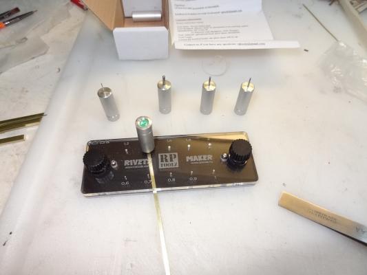

-
Planking for Ships Boats
mikiek replied to mikiek's topic in Building, Framing, Planking and plating a ships hull and deck
Clinker it will be! -
As druxey suggested - I tapered the square stick first. Got that shape matched up to the foremast on the plans. As a newbie, I'm not ready for chiseling yet, so much of the work was sanded. It probably took a lot longer than if I had done some carving first. I'm using a piece of birch I had lying around. My intention was for this to be a practice attempt. I have some boxwood on the way from Crown Timber that I was going to use for the real masts. Seems a shame not to use the birch piece but I suppose getting the practice out of it makes the effort worthwile. I'll post some pix in my log this evening.
-
Planking for Ships Boats
mikiek replied to mikiek's topic in Building, Framing, Planking and plating a ships hull and deck
jbshan - I'll give the 1/32 squares a try. A general question - laying a bent frame piece just about worked in the center of the yawl - the bottom was fairly flat there. However, the bottom fore and aft has a pretty sharp angle. I don't think bending would work. Maybe 2 pieces, one for each side and glued at the bottom (keel)? I do need to remember I will be trying to add a few flooring strips, which would partially cover most of the the frame pieces Am I getting to complicated? As far as planking, I am in agreement. Clinker would look nice but at that size would be tough to install. Oddly, the other 2 ships boats do have Carvel planking. -
Thanks Druxey - Thats what I was looking for. So simple and I always try to make it so hard.
-
Planking for Ships Boats
mikiek replied to mikiek's topic in Building, Framing, Planking and plating a ships hull and deck
Frankie - good points in both of your replies. I believe my sig now has a link to the log. Will find out when I post this. I have already resigned myself to the fact that I will be using non-wood materials for the ships boats. For the inner frames, I cannot get a plank to bend enough to fit snuggly so I am going to try styrene. For your suggestion on paper - what type do you suggest? -
Planking for Ships Boats
mikiek replied to mikiek's topic in Building, Framing, Planking and plating a ships hull and deck
Hey George - I have had a build log for about 2 months and get almost zero responses there. The few I do get say to go to the specific forums for specific questions. Frankly, given the activity I see in the Build Log forum, I have been surprised and a little disappointed at the lack of response to my log. Maybe everyone is tired of Niagara builds. But I digress. At any rate, I get more responses here. -
I can't find anywhere in the MS Niagara plans that tells me the size of stick to use for planking the 3 ships boats - 1:64. The 2 cutters are Carvel planked. The yawl is lapstraked. I'm wondering if I am supposed to use the same size planking for all three or if the lapstrake requires a wider plank. Given the nature of lapstrake, I assume one must start at the keel and work up? From what I can see it is going to require shaping of every plank to get a decent fit. Also, I suppose the planks stop at the transom? Do you just cut a clean edge flush with the transom?
-
I'm a little confused about the steps involved with shaping the various mast pieces. I've decided to start with square stock rather than the kit supplied dowel. Using the main as an example - the entire piece is tapered. The bottom 2" need to be octagonal. The top 3" are square and in between is round. If not for the tapering, I get it. Just do the various shaping per measurements and done. With tapering - do you taper the entire piece first then do the shapes? Just taper the round section? I'm looking for some help on the order of steps in this process.
-
Grant - I hear that mentioned a lot. For some reason styrofoam is the picture that always comes to mind. I'll check it out.
-
I've taken a break from the big boat on my Niagara build and am working on the yawl (lifeboat). It's a sandwich style hull which I have filed and sanded inside and out to get a nice shape. I want to add some realism so I am looking at adding frame pieces, floor strips, etc. For the frame pieces I am trying to use 1/32 x 3/32 planks, soaking and bending them to fit the inside hull. They are bending OK but I'm not getting a nice flush fit in the hull. When I press one in it seems to be at the breaking point. I am beginning to wonder if there is a better, more flexible material for this purpose? Maybe even some sort of plastic? The only requirement is it must be paintable.
-
Good point Mark. My first inclination was to retract them inwards all the way. Assuming at dock you wouldn't want the barrels sticking out and getting caught on some mooring line. But "ready for action" is an important factor. I'm not ready to actually mount the guns yet. I just took a break from the boat and started working on the carronades. I've got several finished except for gluing the top sled to the bottom and that's where the question came up.
-
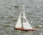
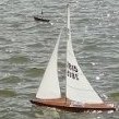
Guessing this area is where my question should go. I'm working on a MS Niagara build. The MS kit has no sails and I'm not planning on adding them. So in the display case Niagara will appear "docked". A lot of the models I see have the gunnery extended out thru the gunports. I suspect during an action this would be the case. I was just wondering on the original ship (or any ship for that matter), how/where the carronades would be positioned when the ship was docked or "at ease"? BTW the carronades are mounted on a 2 piece sled-like carriage. The front of the bottom sled is pinned to the gunport sill - basically stationary. The barrel is mounted to the upper sled which can be moved outward or inward. That's the one I'm wondering about.
-
Hey Scott - don't feel too bad. I am completing the starboard bulwark on my Niagara. In doing so I have literally broken EVERY port timberhead. Some more than once. Stay with it....