mikiek
-
Posts
2,276 -
Joined
-
Last visited
Content Type
Profiles
Forums
Gallery
Events
Everything posted by mikiek
-
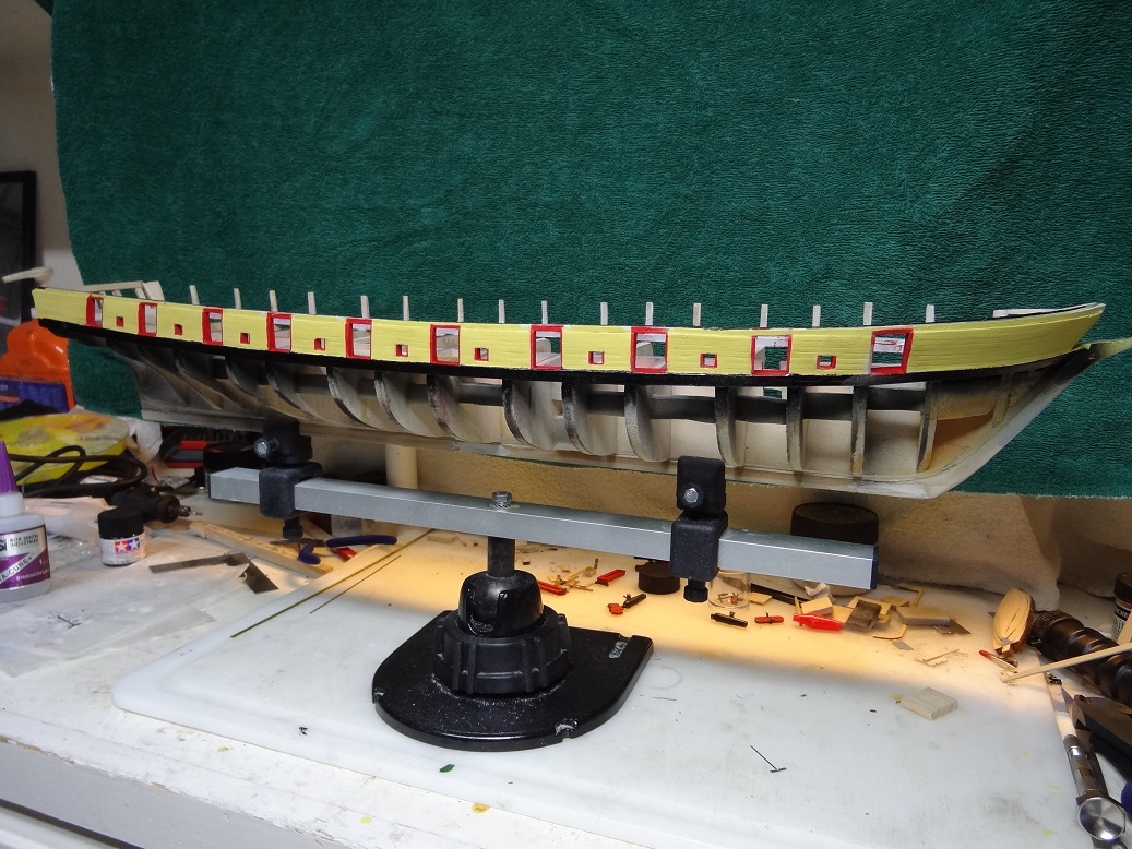
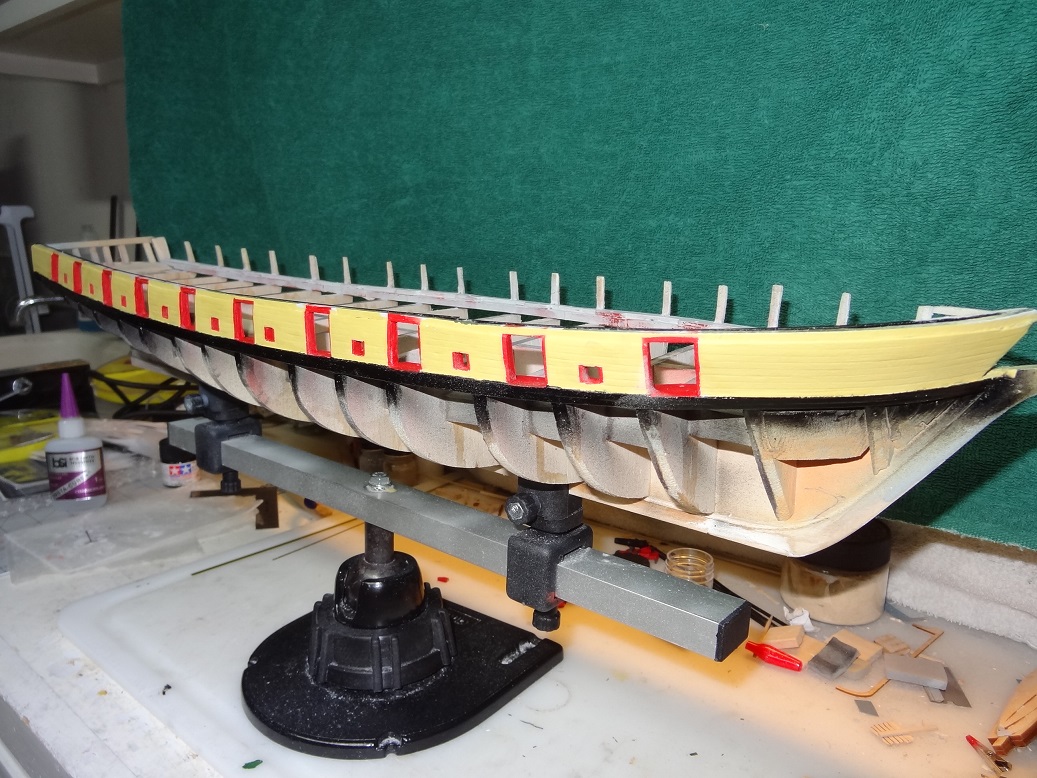
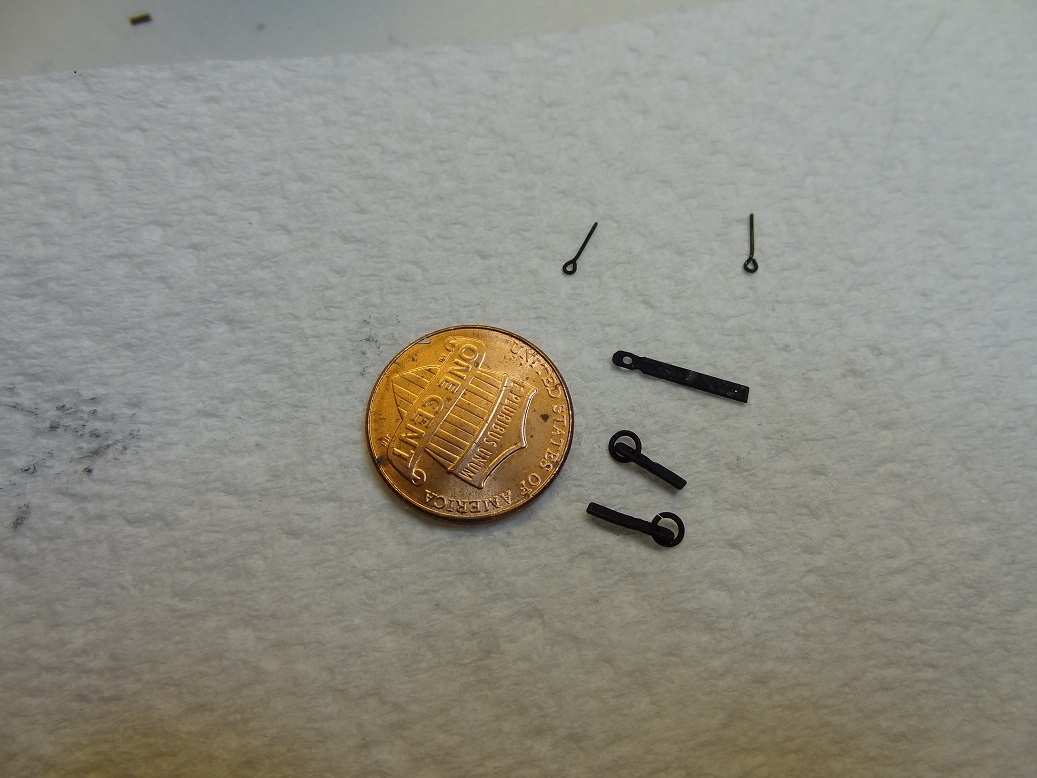
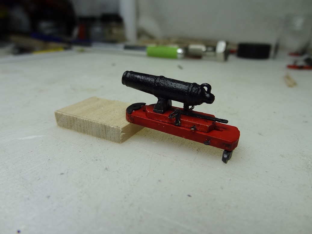
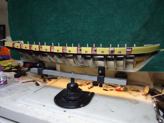
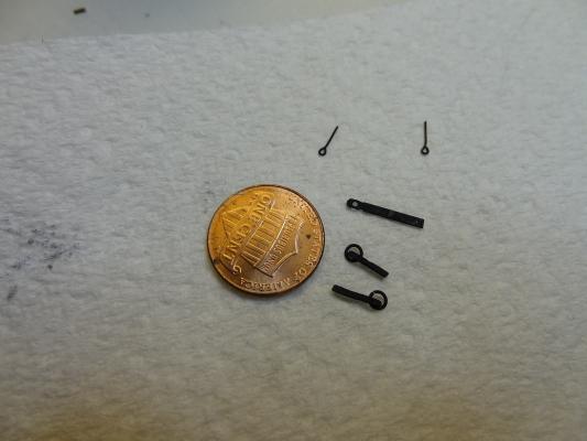
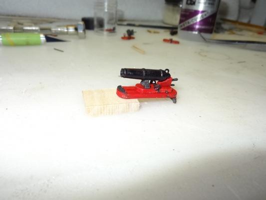
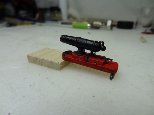
 Wow - it's been a while since a post. I have been working on the build but mostly a lot of little odds & ends with not too much new to show for it. The starboard bulwark is finished, but I am still struggling with my paint job. I'm finding it really hard to get a good solid edge between the yellow and black on the outward side. The 2 colors are such a contrast that any little spot or bleeding really sticks out. I'm also seeing that what doesn't look too bad to the naked eye can look pretty rough in close up pix. I thought painting would cover up some of my mistakes (which it does) but it has it's own set of gotcha's. I've ordered some timbers from Crown Timberyard so I am not doing any wood work at the moment. So I moved off to the guns to try my hand at some metalwork. That has been really fun. First thing I did was go out and buy some reading glasses This stuff is pretty small and I haven't even tried rigging yet. I had to cut and shape some parts from the brass strip (1/16") in the kit. It's funny how the first attempt kind of sucks and then each subsequent try gets better. I had the hand files and Dremel grinder out for this one. Also, it's the first time to use the pin vise and micro bits. They worked better than I thought. I need a tiny center punch to make a starting point on the strip. Got one on order. The parts were blackened using Blue Jacket products (Blue Jacket has a product for pewter and one for brass). It took a while to get the Brittania pieces done . I had a tough time with the barrels. They didn't turn black at first so I kept adding more product. Finally I just left them for a few hours, but when I came back they were discolored - some kind of rusty looking, a few almost pink. However they did have a very nice surface finish - almost crusty. I ended up painting those with some Tamiya black which came out a little glossy so I hit them with some matte varnish hoping to dull them down a bit. The result was actually pretty good I think. The brass blackener worked very well and quickly. I want to work on the straps for the cannonades, to get some sort of rivet/fastener to show up. It's a little tough since I am blackening and not painting. The usual dab of paint didn't look good and ended up flattening out on the strap too much. Glue doesn't work because it doesn't blacken. I believe next I'll try a punch. Another suggestion was RP Toolz punch & die set. They have one they call rivets - the result looks sort of like the head of a carriage bolt. I think that would look good but the set is a little pricey. I also ordered from Crown, square strips for the masts. I am going to try to carve them myself rather than use the dowels that came with the kit. Yet another adventure. Below are a few pix of my progress. I would sure appreciate hearing from ya'll. Critiques are welcome - no feelings to hurt here.

- 843 replies
-
- 6
-

-
- niagara
- model shipways
- (and 2 more)
-
Bolt Heads on Brass Strips
mikiek replied to mikiek's topic in Metal Work, Soldering and Metal Fittings
A nice set Pat - they also have a rivet punch set. Probably more in line with the 19th century. It seems pretty hard to find RP Toolz retailers in the States. I did order a small disc punch set from Micro Mark today. I'll see what those look like. I suspect the rivet may be better looking. We'll see. I'm not having real good luck turning up brass photo etched parts (I'm terrible at Google searches) although that still sounds like a good option. -
Bolt Heads on Brass Strips
mikiek replied to mikiek's topic in Metal Work, Soldering and Metal Fittings
Highlander - interesting idea. I can see that being used in many applications when it comes to the metalwork for this build. I am probably looking for something more like thick wire than a rod. jbshan - yes, that is the strap I am talking about. And you are right, bolt heads will be pretty small! Along with being my first build, this is my first attempt at any metalwork. The pieces I am making now are pretty basic, but they came out nice and I enjoyed doing it. Honestly, bolt heads on a 1/16 strip sounds a little extreme when you think about it. But if I can get details like that into this build it might make up for some of my shortcomings in other areas. I would like to give the drop of paint idea 1 more try - since it is by far the easiest. I think I need to thicken the paint (Acrylic) up so the drop doesn't flatten out. All I've ever done is thin paint. How would you thicken acrylic? -
This has been discussed before and I have tried several of the suggestions but I am not getting the results I would like. I don't remember the name of the part but they are basically small metal straps for the cannonade on my Niagara build. I'm using the stock 1/16 x 1/64 brass strips that came with the kit. All the straps are is strips varying in length from 1/4" to 1/2". A hole is drilled near one end, a ring is added to the hole and the corners on that end are rounded down. Then the plan shows 1 - 3 bolt heads one 1 side. I need to add that I am not painting these pieces. I am blackening them with the Blue Jacket product which works very well. The look and finish on the parts is excellent. So, I have tried a dab of paint with a 000 detail brush. That looks a little too big and even with black paint the color looks odd on top of the blackened brass. Also the paint drop seems to flatten out while drying so I lose most of the relief I was looking for. Obviously a dab of glue doesn't work (before or after blackening). I'm beginning to wonder If I could glue a tiny fleck of brass on the strip and then try to blacken that. I think that might solve some of my problems and could look pretty good. The only issues that I see are 1. How to cut a piece of strip that small 2. When gluing the fleck, I can't allow any glue to get out on to the strip because it won't blacken there. I am open to any other ideas or how to follow out the steps above.
-
I have a Sherline arriving next week. I have to say their Customer Service is very responsive. Sent them an email with a few questions and got a reply within the hour. That raised a few more questions which I emailed back and those were answered in about 30 minutes.
-
Help Around the Edges
mikiek replied to mikiek's topic in Painting, finishing and weathering products and techniques
Thanks Brian - I'll give that a shot. I'm trying to finish off a lot of small tasks this weekend. I would love to get the bulwark painting over with! -
More Masking Tape Questions
mikiek replied to mikiek's topic in Painting, finishing and weathering products and techniques
Hey thanks Chris - I'll look into it. Amazon even sells it. -
More Masking Tape Questions
mikiek replied to mikiek's topic in Painting, finishing and weathering products and techniques
Hey Chris - would a big box hardware store have that or do I need to go to a paint store? Better yet, have you got a brand - I can pick it up online. -
One more post on my Niagara project - keep in mind it is my first build. The bulwarks are painted on this one and I am mostly finished. I say "mostly" because I find myself constantly pulling out the 000 detail brush and touching up spots here and there. When is good enough, good enough? The thing that is killing me is the outer bulwark planking (yellow ochre) on top of the gunwales (black). Two high contrast colors and the edge in between them is a little ragged. I have taped the gunwales and put down some additional yellow on the planks. Then taped the planks and put down some black. But the edges still look rough. Do I just stay at it? Is there a better way? I do emboss the tape at the edge. Someone mentioned using a clear finish over the tape and onto the painted surface. I am a little concerned about what that might do to the finish of the paint (all flat finishes). I know someone has the answer.....
-
More Masking Tape Questions
mikiek replied to mikiek's topic in Painting, finishing and weathering products and techniques
Brian - I have been using Tamiya tape. It still occasionally wicks under. -
Canute - this has been very helpful. Sadly I am not having an easy time pulling the mast measurements out of the plans. In general, is it possible that the diameter of a finished mast might be larger somewhere than the dimension of the mast slot in the keel? Hope that made sense.
-
Is there any rule of thumb regarding what size to start with? For instance the main is a 3/8 dowel. If I start with a square beam what size should that be? I realize just about anything bigger than 3/8 x 3/8 would work, but I'd rather not be whittling for the next month.
-
More Masking Tape Questions
mikiek replied to mikiek's topic in Painting, finishing and weathering products and techniques
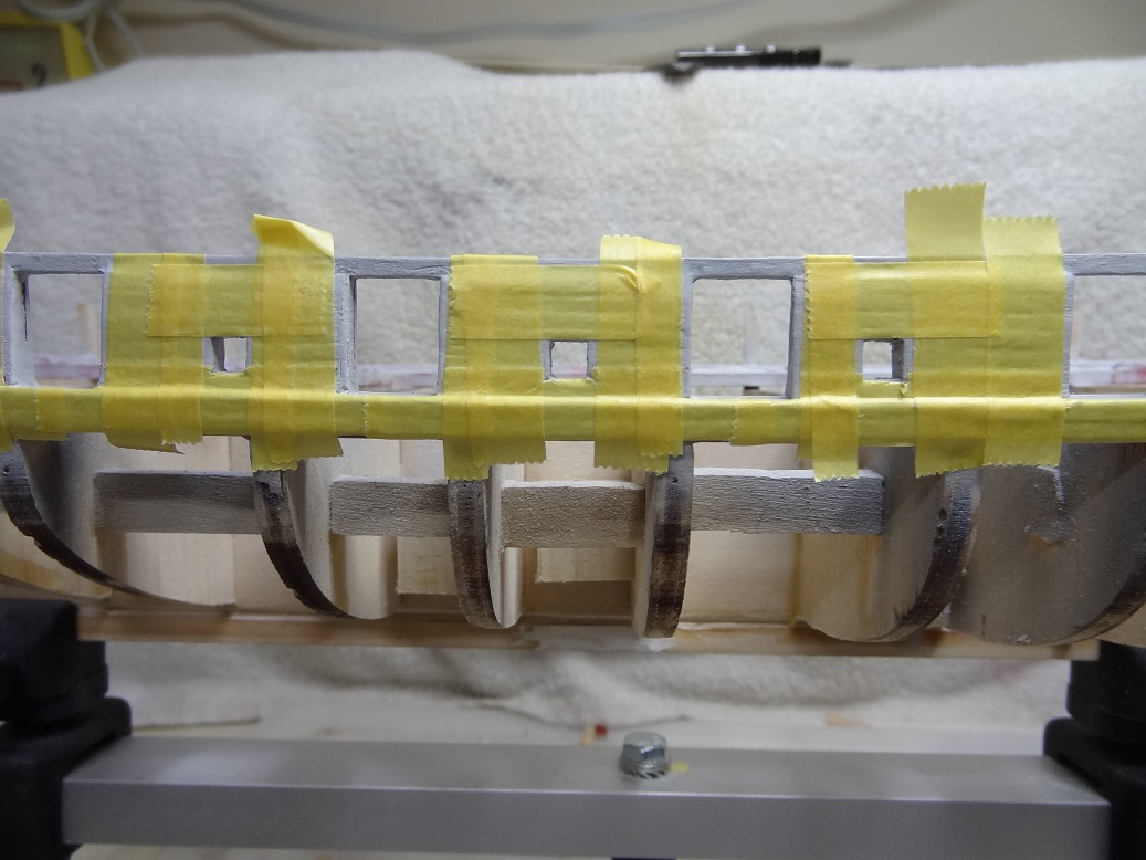
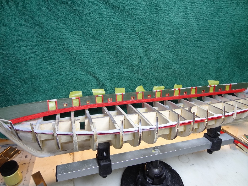
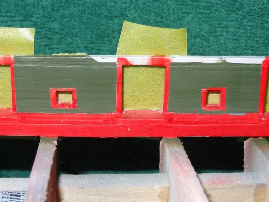
Philo426 - here is just a sample. I taped the entire bulwark wall (still primed) before spraying the red paint which is supposed to be what covers the 1/32x1/32 strips. Look at the painted pic. You can actually see the strips - my masking covered too much of the planks. I went back with a tiny detail brush and moved the green edge in towards the strips. Talk about stressful

-
I'll bet the pine your grandfather gave you was longleaf pine. It was a great wood for construction and it was all but decimated years ago. It was not replanted because loblolly and slash pine (what gets sold as yellow pine) grew a lot faster. Birch or maple should be pretty easy to come by at the big box stores. I'll just inspect the grain and get what looks best. Definitely something I can rip down to a suitable square beam and start from there. I may actually have to pull out the table saw. Thanks to all for your comments!
-
Thanks Jaager - that's good information. I'll take the challenge and go the octagon route. What type of wood has worked for you?
-
Jaager - this is a POB kit. I am about to start on the deck and need to at least get the scrap wood glued to what I was calling the keel notch. The instructions actually call it the mast slot - my apologies if that was confusing. I don't need to do the mast yet but I want to get the wood glued to the mast slots before I forget to do it. Due to that I need to decide whether to go with an octagonal foot (per the plans) or a rectangular foot (what most seem to be doing). If I go octagonal then the slot side pieces will be different to accomodate the additional sides. You are right when you say it will end up hidden under the deck, and personally for the foot I couldn't care less which way I go. My biggest concern was how to cut a nicely centered and even sided octagon or rectangle in a dowel. As druxey states I really should start with a square beam rather than a round dowel. The plans call for the mast to start out octagonal, then round, then octagonal so learning to make this cut is something I need to do. At the moment I just don't know how so I am asking for help.
-
I feel for you jazzchip! And I can relate. I am on my first build as well. No other modeling or woodworking experience. I went with a Model Shipways kit (Niagara) because after some research it seemd like they did a relatively decent job with instructions. Well if this is decent I would hate to see poor! The instructions (at least there are some) are at too high a level - they just glaze over a lot of steps. The plans use the description "typical" to describe a lot of structures. If you have never seen one before, what is typical? I am very grateful to the folks here at MSW. There are numerous build logs for Niagara and I have been going mainly by their pix.
-
More Masking Tape Questions
mikiek replied to mikiek's topic in Painting, finishing and weathering products and techniques
druxey - I am beginning to see the wisdom in that. I actually followed that advice fo the rails. I have not installed any of those parts and as a result I really don't care if anything gets on to the base ceiling strip while I am messing with the bulwarks. A lot less fuss. As a newbie, I didn't realize how strategic a paint job can get. -
I am painting the bulwark area on my MS Niagara. There several colors required and some very small areas to be painted including some 1/32 strips that are red with dark green planks butting up to them. I am using masking tape (Tamiya) and am having to trim many spots with an Exacto. Unfortunately, the knife (or more likely me) is leaving some slice marks in the wood under the tape. So question 1 is are there any better ways to trim the masking tape? Also, I would like to apply 2 coats of paint but I am a little nervous about leaving the tape on while the first coat dries. On the flip side it took 90 minutes of masking to do a 5 minute paint job so would rather not pull off all the tape, let coat 1 dry, remask and paint again. How safe is it to leave masking tape on a painted area? I would like to use some sort of straight edge when trimming tape. However with the model on a stand, a straight edge (small ruler) in one hand and an Exacto in the other ain't easy. Are there better ways of accomplishing this? Thanks in advance....
-
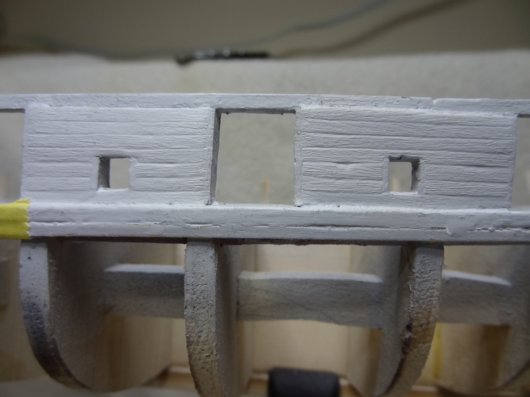
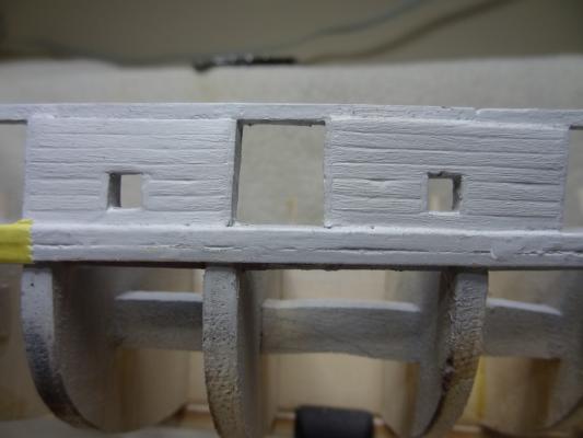
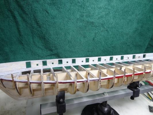
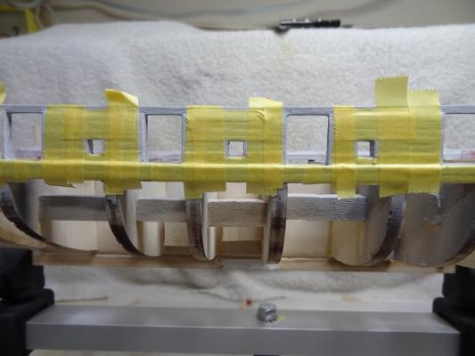
A lot has happened since my last entry. The outward bulwark planking is complete. I've done some filling and began the masking/painting of the bulwark planking. The outward planking went quicker than the inner where I was a adding a few of the plank end cover strips and then doing the planking for those areas. On the outside I did all the cover strips and then went back and laid all the planking. I seem to have a bad habbit of completely finishing out a small section of an area then moving to the adjacent area and completely finishing that out. I'm finding that to be very inefficient. I did learn an interesting technique when going about filling the gaps and uneven planks. I am using Tamiya grey putty as my filler. Rather than just dabbing the bad spots, I appplied a thin layer to an entire section. Before the putty has completely dried I wiped it down with a paper towel with some lacquer thinner. I wiped until I could just begin to see the wood coming back. The last few strokes were made following the grain in the planks - left to right in this case. Interestingly, the papar towel has enough roughness in it to leave a faux woodgrain. I thought it looked fairly realistic, and with more practice could get even better. There's a pic of this below. After all the filling it was time to get around to some painting. I was excited to get started with this - new airbrush rig. With all the ports and different colors Niagara requires a lot of masking. I was hoping to be able to use frisket in some places because it is applied quickly. However, I was never able to get a good straight edge so I ended up doing the obligatory masking tape (Tamiya) and trimming. As was noted in a post in another forum, it was 90 minutes of masking for a 5 minute paint job! I'm really pleased with the airbrush system. I got an Iwata Power Jet Pro compressor (very quiet!) and an Iwata Eclipse and Badger 200NH airbrush. I've still got a lot to learn, but man, the smoothness of the paint layer is wonderful! The Tamiya the paints that were included with the kit needed some mixing. The J.H. Green was darker that I wanted so I ended lightening that up with some yellow and white. It's still dark but better. The Yellow was almost a lemon yellow so it needed some adjusting. Adding fairly large proportions of White and Buff got me close to what I was looking for. All those colors are the flat finish. So I've painted the inner bulwark and today am masking the outer. I hope to get some paint on that this afternoon. The pix show quite a mess on the strip I used for the port ceiling. I have not yet added any part of the railing yet, so I still need to add an inner and outer side cap strip (Black) and then the actual railing (Buff). I went the route of leaving the railing off during all the bulwark planking and painting. This left a bit more room for fat fingers and I also didn't have to worry about masking it. It was a good move.

- 843 replies
-
- 6
-
-
- niagara
- model shipways
- (and 2 more)
-
I did do some painting today and very much as Ulises said - it took almost 90 minutes to mask and trim (with tape) and about 5 minutes to paint. It came out pretty well but there is some touch up to be done. I should have some pix in my build log tomorrow.
-
There's bound to be a simple way to do this. The MS Niagara plans say to cut an octagonal foot and a matching brace. I think all the pix I have ever seen show rectagonal foot as wide as the keel with the braces being just flat scrap glued on each side of the keel notch. Either way, how do you get a nicely centered, even cut on the dowel? Firstly how do you measure it out and secondly how do you cut it? Inquiring newbie's want to know. I imaging I'll just go for the rectagonal cut, but I'd like to know how one would get an even sided octagonal foot? If I am not mistaken, there are several parts that are called for being octagonal.
-
Well I tried laying down some tape on scrap wood and then painting on the frisket with a little overlap onto the tape. The frisket takes forever to dry so I gave it overnight. Next day, tried pulling the tape off in the hopes that the overlapping frisket would come off with the tape. It didn't. So I ended up with little flaps of frisket hanging out into the area to be painted. It may have worked better running a knife down the edge of the tape first. It's starting to get more troublesome. Beginning to think I'll just do it the usual way - lots of tape and cutting around edges. The Tamiya tape seems to cut very easily.
-
David - great idea! I like the way you are thinking. I have finished the outward bulwark planking so I have the starboard bulwark covered. That means tomorrow is a paint day. I will be sure to give your idea a try.
-
David - what you are referring to is the frisket I mentioned in the OP. It can be applied with a brush, which I like. I am having some problems after the application, cutting straight edges with an Exacto. Same story with the rubber cement. It doesn't peel away evenly at the cut.