

Trussben
-
Posts
1,798 -
Joined
-
Last visited
Reputation Activity
-

 Trussben reacted to Chuck in Sloop Speedwell 1752 by Chuck - Ketch Rigged Sloop - POF - prototype build
It was so great to see everyone at the New London show yesterday. There were some fantastic models on display. I hope everyone has a safe trip back to their workshops.
And talking about a safe journey back to the workshop. Many of you may recall that 4 and maybe even 5 years ago, Someone swiped my mini-me off the Winnie model under construction at the show.
I am happy to report that after several years as hostage…and with no ransom paid, someone anonymously released mini-me and placed him in the depths of the speedwell model at this years show. I was happy to find him below deck upon my return to the shop. No harm was apparent on “mini-me” and he is in good health. Thank you goes out to person for having a change of heart and I am sure that both of you will sleep a bit more soundly this evening!! Since I have lost 30 pounds this year so far...mini-me will now undertake the same dietary and exercise regime that I am now unfortunately tolerating.
You cant make this stuff up!!!
-
Trussben reacted to scrubbyj427 in HMS Portland 1770 by scrubbyj427 - 1:48 - 4th rate 50-gun ship
Small update, I’ve added the upper laser cut planking panels to the model, these will be the ones used in on the final model, with a few slight modifications that I’ve overlooked but corrected on my model. To begin I placed a board across the beam to ensure the proper height of the panels and I clamped them as I went along, once I was happy with their location I ran a batten underneath both of them to ensure that the planking that will follow below will have a smooth joint and continuity with the laser cut panels, once the panels were tweaked to fit right I then glued them into place using CA.
you can see below that I made some adjustments to the aft panel so the forward one would line up with the gun ports.
You’ll also notice the grey primer, I find this necessary with MDF as it’s super porous and soaked up three coats of solvent based primer. The primer also will not swell the MDF and allows it to be sanded smooth in preparation for whichever red you choose for your port framing.
The batten ensured that I could set them right back where they belong without losing the correct position. I kept the front one clamped in its location while I glued the stern one, this ensured that there was no lateral movement of the aft panel.
The same process was repeated for the front panel.
I also begin the lower wales, you’ll notice the same process where I used a batten I reference to the marks on the bulkheads “W1”. The batten goes on the lower side of the line, once the batten passes the eyeball test then it’s time to start the wales, now the wales on this model are over 1/8” thick so unfortunately they will have to be done in two pieces, the first layer I’m cutting them at .080” with a significant taper in the front to fit the rabbet and allow for another layer to go over it and fit in the rabbet as well.
I’m not really concerned with the length or butt joints of the first layer of planks as they will be covered up, just get a smooth run with tight joints.
Unfortunately I can not proceed any further until I complete the counters, I have a laser cut lower counter that I will be testing soon and from there I will plank the upper counter using the laser cut lower as a guide.
I will be off for a month in the Himalayas, hiking to Everest base camp and beyond, so I won’t have any updates until about June, possibly one more before I go but will see.
Thanks for looking in.
JJ
-
Trussben reacted to glbarlow in HMS Winchelsea 1764 by glbarlow - 1:48
Fenders and Chesstrees
Keeping with shorter posts: Added the fenders and chesstrees to the hull.
Each consist of a center and two outer layers glued together providing a nice dimensional look. After removing char the center piece is tapered from top to bottom and the outer edge slightly rounded before the two very thin are added (amazing to have layered wood on this thin a sheet of wood). With great trepidation I removed the center moulding. Then came a lot of careful shaping to conform these to my particular hull - both patience and time are required following the firm rule of while you can remove wood, you can’t put it back.
I tried printing the frieze on tissue paper, really I tried. While successful the color and texture just weren’t a good match for me, probably the wrong tissue paper or I need more practice doing it. I was however successful using the original paper printed frieze. Ample use of the same glue stick used for the hull softens the paper and allowed me to get a match. With Chuck’s suggested tooth pick approach I was able to guide the paper into the groove created by the three pieces.
I also rounded out the sheave on the chess tree before applying the outer pieces along with a little 7mm lead pencil.
I’ve still not mounted the waist cannon, but set them for the photo. The addition of the fenders, chess tree, and ladder really bring the hull alive. My one regret is while the boxwood for the ladder match, the AYC for the fenders are way whiter than the hull despited several coats of WOP. I kinda wish they had been boxwood as well to match the moulding.
I note however, at this point the hull planking is near three years old. I am confident in time the fenders and chess tree, like the hull, will mellow and blend in.
I’m moving onto the waists platforms and will finish chapter 11 with the channels. Thanks for stopping by.
-
-
Trussben reacted to Chuck in Sloop Speedwell 1752 by Chuck - Ketch Rigged Sloop - POF - prototype build
The knees wont be seen so they will be omitted. Its easy enough for folks to add should they want to. Thats a benefit of having Davids book while building the kit. But it will really complicate and make adding all of those ledges take forever. And all for something that will never be seen. I think most folks will be relieved not to make them.
the contemporary model doesnt have them either. My guess is for the very same reason.
It also reduces the cost and time to manufacture the kit quite a bit. I did add them on the fcastle however because the ends of the knees will be slightly visible in the open area left unplanked. So once the gun deck is planked…the casual viewer will actually assume you did add all of those knees for the entire model. LOL
I will take a picture with the planking templates in position. You will see what I am talking about pretty clearly. The same is true of all the ledges down the center line. They will not be seen either. The contemporary model also omits these..whats the point really.
-
Trussben reacted to Chuck in Sloop Speedwell 1752 by Chuck - Ketch Rigged Sloop - POF - prototype build
Thank you guys...it will be at least a week before I can do more on the model.
-
Trussben reacted to Chuck in Sloop Speedwell 1752 by Chuck - Ketch Rigged Sloop - POF - prototype build
I have reached another small milestone. All of the below deck fittings and cabins are completed. The gun deck is fully framed as well. Next up I will start planking the inboard bulwarks. That should make a huge difference.
I hope to see many of you this weekend at the New London show. It should be a very enjoyable weekend. I am looking forward to it.
Chuck
-
Trussben reacted to druxey in Sloop Speedwell 1752 by Chuck - Ketch Rigged Sloop - POF - prototype build
Wait a moment - I've got a match here somewhere....
-
Trussben reacted to Chuck in Sloop Speedwell 1752 by Chuck - Ketch Rigged Sloop - POF - prototype build
Thank You...
The cabins on the aft lower platform are completed. No detailed explanation since they are built exactly like the others. Each partition wall is built up with two layers glued together. Then they are detailed with hinges and door handles as required along with any upright timbers 1/8" x 1/8" strips. Their heights and widths are adjusted to fit under the deck beams etc. Finally they are assembled and glued into position.
Here is the tiny powder and filling rooms completed. These walls are slightly thicker than the other cabins as was normally the case. An extra laser cut sheet of parts shows how all the cabins are prepared for you. They are all numbered and shown on the plans. I built them in the order that they are numbered.
All of the cabins completed.
Next up is to complete the remaining deck beams carlings and ledges.
-
Trussben reacted to Chuck in Sloop Speedwell 1752 by Chuck - Ketch Rigged Sloop - POF - prototype build
Thank you for saying...
I am trying to set aside time regularly to make a little progress.
Continuing with the center line fittings below deck, the WELL was next up. This is a relatively simple structure. The four sides are laser cut and etched. You need to do just a few things before you glue up the four sides.
First...make sure the fore and aft sides sit nicely on the keel. Once you adjust them as needed, you can cut the four upright columns to length. How do you determine the length of these. The two aft columns are shorter. These are simply cut to fit under the next deck beam. No big deal. The two columns on the fore side of the well are different and taller. These two columns are cut so the tops are flush with the TOP of the gun deck beams or carlings.
You will have an opportunity to sand these shorter so dont over sand them initially.
Assembling the well is straight forward after you glue the columns to the port starboard sides of the well ahead of time as shown above. You can also use some scrap tiny strips of wood to make the toggle handles for the access door. Then just glue them on. They are clearly shown on the plans.
With the four sides glued up and square...test it on your model. After any minor tweaks you can glue it position permanently.
Then the next few gun deck beams, carlings and ledges were taken care of. Eventually you will get to the beams where the capstan step needs to be built along the center line. So you will need to stop and assemble the capstan step. I glued those appropriate deck beams in position so I had a reference point to test fit the step periodically. The step is also laser cut for you and has a recessed circle in the center. This will accept the heel of the capstan drum...eventually.
The step is bolted to two columns that are set on top of keel. These two columns are 1/8" x 1/8" strips just like the other support columns under the beams. Hopefully you havent forgotten to add any up until now. They are all shown on the plans.
You must cut the two columns to fit under their respective gun deck beams. Now you have to determine where along those beams the capstan step will be placed. You can use the plans of course but it is doubtful it will match your model perfectly. Mine didnt. So just understand that the capstan step is slightly higher the lower aft platform and it is level. Because you know this you can mark the columns for the height of the capstan step with the columns "snug" fit temporarily in position.
When I was comfortable that I had the proper height worked out, I was ready to glue it in position. But first I had to add the simulated bolts on the capstan step. I used 25 lb black fishing line to simulate these. And yes the photo shows the step upside down so you can see the hole for the drum. But rest assured it will be glued in position right-side up!!
The capstan step in position...and the carlings added afterwards.
And some other views...of the gun deck up to this point with the ledges completed.
Almost to the other side of the gun deck. But next up are all of the cabins on the aft lower platform. Onward and upward as they say!!
-
Trussben reacted to Chuck in Sloop Speedwell 1752 by Chuck - Ketch Rigged Sloop - POF - prototype build
The Speedwell castings arrived. Just like the Winnie these are cast in a very light Tan. Almost white but not. This is a big help for the finishing. They were treated just like those on the Winnie. See the unfinished quarter badge on the can of gel stain?
I used Old Masters gel stain. The color is Fruitwood. This is the best color for our purposes in my opinion. Just brush it on and let sit for a few minutes. The longer you leave it on the deeper and darker your color will be. Dont leave it on too long...you can always add another coat after it dries.
Brush it off before it dries however with a soft clean brush. Almost buff it. The more you brush the more you will remove. This evens it all out while leaving darker bits in the deeper areas. But not overly so.
The one drawback with this method is the parts tend to get shiny. But a quick spray with some dull coat after it dries does the trick. The color matches quite well as you can see. This preserves all the detail as well because unlike paint, this does not build up and obscure the small details.
-
Trussben reacted to Chuck in Sloop Speedwell 1752 by Chuck - Ketch Rigged Sloop - POF - prototype build
Thank You...
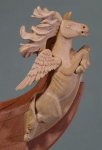
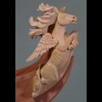
With the framing almost completed I was able to finalize all of the master carvings. I did the final prep work for casting. They will be sent off to be cast in a light tan like the Winnie carvings. I hope they can get some sets to me soon.
Here is a look at the quarter badges. They are quite small actually. I will let my casting guys alter these because there are some areas that wont cast well. For example under arms of those tiny reclining figures. Those open areas will need to filled in order to cast these.
-
Trussben reacted to Chuck in Sloop Speedwell 1752 by Chuck - Ketch Rigged Sloop - POF - prototype build
Next up is the Wing Transom....
This is pretty straight forward. Especially after shaping all of those frames. This is laser cut but still requires some shaping because of the many angles.
I removed the char from the top and bottom first before adding the provided templates. You can see the untouched wing transom in the photo as well.
The top template is glued on with rubber cement. The top has the notches in it for the stern frames and quarter piece.
Then the bottom template.. pretty easy so far.
Then use a sanding stick to sand the bevels on each side using the templates for a guide. This will create the desired parallelogram shape.
Then the wing transom is glued into position. Make sure your hull is vertical on the build board. Especially the stern post. Then use your squares to line it up with the build board plan. Make sure the height is the same port and starboard. Use titebond here so you have more open time to level this and get it all squared up.
Then it is time to add the last "top jig".
But before doing so, I must mention that the forked bracket will be removed that holds the stern post vertical. I know...its important. But seriously we wont be needing it any more. We will add the last top jig first and then remove the bracket immediately after. This way you can still use that string to check that this last jig is aligned and centered.
The last jig is added just like the previous two others. Make sure its aligned down the center. Make sure its the same height port and starboard. You can use a string like before and a square. Once satisfied and taped in position along the puzzle piece connection, you can remove that forked bracket as shown in the photo below.
This last top jig actually comes with two rectangular holes on top. There are two keys that slide into them which will now hold the stern post perfectly vertical. They are "T" shaped. Dont glue the keys in position. They are snug tight fit. Just push them into the holes. See how they holds the stern post vertical? You will want to remove the keys if you decide to turn the hull upside down to fair the hull later. It wont sit flat with the keys in position. But we only need to use them for a short time.
Then the quarter pieces are added. Here is the one on the starboard side completed. I will detail how its shaped when I do the other side. I know this may look a bit odd to some folks but its all going to workout in the end.
There are some laser etched bevel lines etc on these pieces and I will explain how they need to be handled and in what order.
But basically, this quarter piece sits on the end of the wing transom (a notch is there so no quess-work) and the top is angled inboard to match the sloping sides of the hull. It sits against the edge of the "top jig" The forward end is glued to the aft face of the last cant frame.
Note how it extends over the wing transom a bit further aft by about 5/64". That is correct on done on purpose. It will be important later when we do the square tuck.
Having this all done and laser cut in one piece makes it a lot easier. The framing as you can see in the photo would have been tricky. Just read through Greg's log to see how tricky it is. I was initially going to just leave this part solid but then I decided to have a little fun. I made it look like the framing was actually there even though we are planking from the wales up anyway.
We will add the remaining cant frames (really only half frames) soon. They fill in the bottom below this quarter piece.
When faired and planked nobody will ever know. The hull framing is getting there!!! Nearly complete.
And a snapshot of the working plan....just for clarification.
-
Trussben reacted to Chuck in Sloop Speedwell 1752 by Chuck - Ketch Rigged Sloop - POF - prototype build
Just a quick update...all of the aft cant cant frames in this step have been completed. This includes framing the sill for the aft-most port and the frames there. Then I just completed the remaining few. Fairing was done on both sides as well. But I still have to add the treenails to those aft cant frames. I will do that first before moving forward to the next step.
There are still a few cant frames left but that will be done in the next step...
That will require a new jig along the top of the model for alignment and I must make the wing transom as well.
More updates to follow soon. But its getting there.
-
Trussben reacted to Rustyj in Sloop Speedwell 1752 by Rustyj - Syren Ship Model Company - 1:32 Scale - POF Sloop
It was mentioned earlier that it's best to sand pieces prior to removing the from the billets. The way I do it is with a sanding block. I use 180 the 320 grit sandpaper. It's self-adhesive. It is also handy for finish sanding completed pieces like the stem. I usually use Minwax wipe on poly. My local store was out but they did have Watco satin wipe on poly. I've used other Watco products and liked them so I gave it a try. It's a little thicker than the Minwax but covers nice and looks the same.
Next I'll start working on the keel. Oh this is fun!
-
Trussben reacted to Chuck in Sloop Speedwell 1752 by Chuck - Ketch Rigged Sloop - POF - prototype build
Just a quick update. It might not look like a lot of work was done since my last post but you would be surprised how involved the deck beams can be.
With the cabins on the fore lower platform completed, you can start adding deck beams above them. No reason to wait until everything is built below deck to do so. In fact, waiting to do it all at one time wont be very enjoyable. Doing it this way breaks up the task a bit.
This kit will be very simplified compared to the books. Because we will be planking the gun deck in the "classic" contemporary model style, there is absolutely no need to make and add the hanging and lodging knees. In fact, this would up the difficulty factor by about ten. So we will just be adding the deck beams with all of the carlings and ledges. You can however follow the Seawatch books and scratch build the knees should you really want the total experience.
The photo below has a lot going on that was completed.
First, The first four deck beams were glued into position...
Then the carlings were added between them as shown on the plans. The carling are cut to length using 3/16 x 5/32 strips.
Lastly you may notice that the after most beams have a column under them at the center. These are just 1/8" x 1/8" strips cut to length. The corners are chamfered as shown on the plans.
With the first four beams added you can now add the ledges. These are the thinner "partial beams" that extend from the carlings to the deck clamp. They are laser cut for you with a special "leg" on the outboard ends. This raises each ledge to the perfect height so it will be flush with the top of the gun deck beams. So when you are cleaning the char off these...DONT sand the bottom or even the end with this "leg" on it. Otherwise you wont have level ledges with your beams. Hope that makes sense.
Now in that same photo above you can see the first few ledges (cleaned of laser char...no need to clean the bottom at all actually) resting in position. All you have to do is cut the end that sits against the carling and glue it on position.
NOTE: Now yes indeed...all of the carlings should be notched in the deck beams. All of the ledges should be notched into the carlings. But you know what...I am not going to do that. And you dont have to either. It simplifies things so much this way and those many mortices and notches are not so easy to make. They will also mostly be completely covered up. So you can decide.
Now this may all seem simple enough. But finding the exact locations for these beams, carlings and ledges is super important. Time and care must be taken to get their location correct....otherwise you will end up with hatches in the wrong position and mast holes too!! It could get ugly.
So use the plans. If you have a second set printed. Go ahead and cut them up. You can see strategically placed cut outs on the template that allowed me to mark the locations of the carlings on the beams....and the ledges on the carlings. This template also helped me position the deck beams properly which is the very first thing you need to do. Finding you center line on those deck beams after they installed is also a huge help. Gluing the parts in is easy enough...but the marking, measuring and planning takes time and patience.
Then its just a matter of cutting all of those ledges to length and gluing them in position. There are a lot of them. I believe 86 in total. Note that these would also be down the center between the carlings and hatches also. But once again they will be entirely covered up and its just a repetitive exercise that nobody will ever see.
To show you how the knees and other details like the ledges wont be seen...here is a look at this area with the deck planking cut and placed on the model as a test. This shows what will be very close to the final appearance using the "classic contemporary model appearance". But everyone can always deviate from that should they want to.
-
Trussben reacted to Chuck in Sloop Speedwell 1752 by Chuck - Ketch Rigged Sloop - POF - prototype build
Thank you guys...
I took a crack at the sailroom.
First I had to make the posts for the partitions.
There are thin laser cut strips that need to be glued to the sides of some 3/32" x 3/32" strips. It might be hard to see but the laser cut strips are wider than needed. You have to line up the open side with the edge of the 3/32" strip. Let the other side hang over. The upright on the left shows this. Once the glue dries, you can sand that overhang down flush with the 3/32" strip. This will leave rows of slanted slots for the louvers. They should be open on both sides after sanding off the overhang. There is also a long slot down the front edge that is created. This is for the planked bottom of each partition.
It is all shown on the plans. The corner post gets two of these laser cut strips with the notches. Just be careful when you glue them on so they are facing the right direction and the louvers will be able to slip into the slots easily.
Next I added the laser cut planked bottoms. This essentially makes a nice two-sided partition. The planking will fit into those long notches on the posts. It is probably easier to see them in the photo below. Keep a nice 90 degree corner with both sides.
Then its time to fit all of the louvers...for ventilation.
They are 3/32" x 1/64" strips. Just cut them to length and start adding them. Eight on each panel.
To finish off the sailroom..I made the door. This is in two layers like all of the other bulkheads. I made the door up and added the hinges and door handles. Then I glued it to the louvered section of the sailroom.
Like this.
Now I could easily position the entire sailroom...hopefully. It should line up and fit onto the 3/32" post already on the boatswains cabin. And yes...we can finally glue the riding bitts into position permanently.
This pretty much finishes the cabins at the bow. I was originally going to add a sail rack in the sailroom. But after a lot of thought I realized it would never be seen. The sailroom is pretty much covered up entirely by the deck planking and the deck beams.
In this photo I have fitted the deck beams as a test. There will be several more between these larger deck beams too. There are thin 3/32" deck beams...sometimes 3 or 4 between each of these larger deck beams. They will obscure so much of the lower deck items. But hopefully you will get a glimpse of some of this stuff as it is quite a bit of work to build it all.
The contemporary model with its many deck beams..
-
 Trussben got a reaction from JeffT in Sloop Speedwell 1752 by Capt Morgan (Steve) - Syren Ship Model Company - 1:32 Scale - POF Sloop
You can also get large plans printed and shipped to you online, on paper or mylar if needed.
https://blueprintsprinting.com/account/
-
 Trussben got a reaction from Rustyj in Sloop Speedwell 1752 by Capt Morgan (Steve) - Syren Ship Model Company - 1:32 Scale - POF Sloop
You can also get large plans printed and shipped to you online, on paper or mylar if needed.
https://blueprintsprinting.com/account/
-
Trussben reacted to Jim Rogers in Sloop Speedwell 1752 by Jim Rogers - Syren Ship Model Company - 1:32 scale - POF Sloop
Received a large box containing Speedy about 5 days after placing order. The first thing I always do is inspect parts. Many parts where loose in the box so spent a couple of hours figuring out whence they went and taping them in place.
-
Trussben reacted to CaptMorgan in Sloop Speedwell 1752 by Capt Morgan (Steve) - Syren Ship Model Company - 1:32 Scale - POF Sloop
Hello everyone:
Just a quick update. I got the stem tapered for the figurehead and also have the rabbet installed.
Moving on to assemble the front apron all the little wedges for that.
Little steps...
Steve
-
Trussben reacted to CaptMorgan in Sloop Speedwell 1752 by Capt Morgan (Steve) - Syren Ship Model Company - 1:32 Scale - POF Sloop
Hello everyone:
This seems to be the day to start Speedwell logs.
I received my first 2 chapters about a week ago. I don't think I will be buildings as fast as some others but I have started and we are off & running.
My only thought so far is when attaching the two curved pieces together make sure they are as exact as possible. Mine were off a little, and then you have to sand them to get a good fit with the stem assembly. And trust me - you don't want to sand any mating surfaces you don't have to...
I think I finally got a decent fit. It took a lot of extra time but worth it. Now a little extra sanding for the figurehead and the fancy piece on the top. Then it will be time to get the plans out and lay the keel.
I also hope we can start a group build. It might encourage a few others to join us.
All for now
Steve
-
Trussben reacted to Rustyj in Sloop Speedwell 1752 by Rustyj - Syren Ship Model Company - 1:32 Scale - POF Sloop
I got the extra printed plans back and have completed the build board. I got a 3/4" (19mm) thick MDF board for the base. I also put two 1"x2" boards length wise underneath to ensure the board does not go out of shape. It also elevates the base in case I want to use clamps for some insane reason. The plans were attached using a 3M spray mount adhesive. It worked really well.
I also put together the keel support jigs. On to the stem next.
-
Trussben reacted to Rustyj in Sloop Speedwell 1752 by Rustyj - Syren Ship Model Company - 1:32 Scale - POF Sloop
Hi all.
Another Syren Speedwell starting here. I received mine a couple of days ago. I haven't done more than look the wood over, print chapter one of the monograph and order copies of the first three sheets of the plans. The first two sets of parts look fantastic. As you would expect the cutting is first rate and the AYC is so nice.
My first steps will be to read the monograph a couple of time plus review Chuck's and Mike's build's. Also, I'll get the wood for the build board and glue the plans to it. Once I've completed that I'll start in on the stem.
Let the adventure begin!
-
Trussben reacted to Chuck in Sloop Speedwell 1752 by Chuck - Ketch Rigged Sloop - POF - prototype build
Starting chapter 7
The first thing I wanted to do, just to get it out of the way...was to get all the gundeck beams made. I cleaned the char off of all 11 beams now. Then they were cut to length using the plans as a guide. I also used the plans to establish where each deck beam is positioned. For now I will just set them aside and grab them as I need them. The last thing I wanted was to have to stop what I am doing just to clean char off a beam and cut it to length. Its a comfort knowing they are all done and ready.
The photo below shows all the beams just resting on the deck clamp.
This allowed me the opportunity to cut all the templates and see what the planking scheme would look like so I can adjust it now rather than later. I think its a good plan as is...and I wont make any adjustments, yet.
With the beams all ready and at hand, I could start making the cabins on the lower platform at the bow.
Each bulkhead will be made in two layers. Both are 1/32" thick and are laser etched with a bunch of reference lines. Now it would be easy enough to make these from scratch but this does make the building process quicker. Especially since very little of these will be seen. Below are the sections for the carpenters cabin on the starboard side. It shows both sides. I cleaned the char from the inside edges of the door panels and then glued up each layer.
Before I add any details I made sure they fit on the model. I adjusted them to fit nicely in position and adjusted the heights etc. This is why it is good to have those deck beams handy. You need to have the first two beams in position to get the heights correct.
Once I was sure they fit on the model OK (see the deck layout for details), I started added the hinges and stanchions.
First I added the upright timbers which are either 1/8" x 1/8" strips cut to length or 3/32" x 3/32" strips. The plans show which. Then I added the door handles and hinges. Make sure to add the handles on both sides of the door. And be careful to put them on the correct side based on which way the doors open.
The outside view of both bulkheads completed.
The interior of the carpenters cabin detailed.
Finally they were glued into position on the model. I placed the side with the doors first. Just use your planking of the lower platform to position it straight and against the stanchion on the fcastle bulkhead.
Then I added the smaller section along the aft edge of the platform. This will probably need the outside edge to be sanded because I laser cut them longer than needed. So adjust the side that butts up against the frames. But remember, there isnt any planking on the inboard side of the frames so it is expected to show a gap. Just get it as even and consistent as you can.
The carpenters cabin and boatswains cabin completed.
Note how the top of the bulkheads against the deck clamp are flush with the top of the deck clamp.
Next up will be the sail room. But that needs to be built a different way because of the louvered walls for ventilation.
Chuck