

Trussben
-
Posts
1,799 -
Joined
-
Last visited
Reputation Activity
-

 Trussben reacted to scrubbyj427 in HMS Portland 1770 by scrubbyj427 - 1:48 - 4th rate 50-gun ship
Allan, for scantlings I found that the deck plans were a great source. The resolution of the scans really allowed me to zoom in quite far in CAD and produce accurate copies. They also worked well in correlation with the inboard profile of Portland. I kept the dimensions of the Timbers very close to the original drawings (keeping modeling and wood production in mind), I ended up with a good representation of what the drawings show.
-
 Trussben got a reaction from davec in Sloop Speedwell 1752 by Chuck - Ketch Rigged Sloop - POF - prototype build
Very nice touches Chuck.
-
Trussben reacted to giampieroricci in HMS PEGASUS by giampieroricci - Scale 1:36 - Swan-Class Sloop from plans by David Antscherl & Greg Herbert
I finally finished the first set of sidewall decorations:
-
Trussben reacted to Chuck in Sloop Speedwell 1752 by Chuck - Ketch Rigged Sloop - POF - prototype build
I finished up the aft platforms...
They were both planked with the scuttle lids being finished as described earlier. But then two upright timbers were cut to length (3/16 x 3/16) and placed on both sides of the open hatchway. This gives it more support so you can Carefully cut away the beam between them. It will look like the pic below when done.
Then you can make the short ladder that goes in that opening between platforms. This is typical and laser cut for you. The only difference is that this ladder is tilted or skewed sideways. Its an interesting detail. The reason for this will become clear when we start building out all of the cabins. There is a small square with the angle you will need for this ladder on the plans. See below.
This is what it looks like in position. Brutal close-ups...
Then I figured it would be fun to build and install the shot lockers.
All pieces are laser cut. The sides were glued on top of the back piece first. They were placed at right angles neatly.
Then the front is added...which is shorter and has laser etched plank details.
Next comes the top piece. This was laser cut a bit wider than needed for wiggle room. It was glued on top and then the back side was sanded flush where the top hung over the edge. The lids were also prepared. It is one piece with some laser etched details. Basically you have to bevel the top and bottom edges. Quite a bit as you can see.
Here the lid piece was added. It has etched reference marks for the hinges. The hinges are laser board and added the same way we did them for the fire hearth. The top and bottom halves of the hinge are separate pieces. They are glued on first. Then to finish them up a small length of 24 gauge black wire was used to simulate the hinge pins between them.
And finally added to the model...you may have to adjust the height of the shot locker AS you are building it. It all depends on whether or not you placed the height of the aft platform differently. Maybe you placed the platform lower and thus your shot locker may have to be shorter. Measure twice and cut once sort of thing...its so important to get the platform heights correct. But if you didnt, thats OK...just do some problem solving and with some adjustments you will be just fine. I would even go as far to suggest that you test the back piece in position before you assemble the shot locker. Then you will know if its too tall or short and you can adjust accordingly.
-
Trussben reacted to Chuck in Sloop Speedwell 1752 by Chuck - Ketch Rigged Sloop - POF - prototype build
Thank you very much!!!
I am just doing busy work...planking those aft platforms. But I thought this small detail was worth mentioning. Maybe some of you will think this is a good tip to use on any model.
The lower aft platform is planked first following the plans and templates provided. But as seen on many ship models there are scuttles which have rings for handles. Similarly you see these type of rings used for the gun tackles on decks etc. Most folks will make a split ring and then insert this into the eye of an eyebolt. You have seen this a million times.
The photo below shows just that. Look at the bottom row. On the left is what you typically see. The split ring on an eyebolt. Nothing wrong with this as everyone does it this way. But even when the eyebolts have smaller eyes you will end up with so many unsightly rings on deck or on your scuttle lids that look out of scale and sticking up. Yes, you are supposed to sink the eyes part-way into the deck which is a real pain. But even then, it looks very odd to me now after examining so many contemporary models.
So to the right is a solution for this which I keep meaning to post... but always forget to.
The split rings in this case are made from 24 gauge black wire. They are made as usual...wrapping many times around a #47 drill bit and sawed off to produce a 15 or 20 rings.
Rather than make and use tiny eyebolts I just take a small length of thinner 28 gauge black wire and make a small bent "V". This makes it easy to handle and slip the split ring onto. Then I crimp the 28 gauge wire tight around the split ring with a small pliers. Its very simple indeed. Squeeze the two ends together and snip off the bottom on an angle so you have a point. It looks almost like a cotter pin of sorts. This is slipped into a hole drilled on deck or in this case the scuttle lids.
I saw this done in my favorite book. "Legacy of a Ship Model" by Rob Napier. During his restoration of the Princess Royal model he took the model apart...I mean all of it. In the book there are so many photos of these items which show the way the contemporary model builders made their parts. This is how the contemporary builder made these on that model (250 years ago) and after carefully examining so many other contemporary models I believe most of them were made just like this. There is an excellent photo of the contemporary version of one of these in that book....along with countless other gems showing how those guys did stuff back then. Rob had to make more of these for his restoration and used the exact same method of course.
This makes the handles and rings look so much more to scale. No more pesky eyes sticking up that are too large all over the deck for the crew to trip over. Its a small detail but I thought worth mentioning now that I remembered to do so. At least I hope you think so. Its the small details that make a difference when you add them all up...
Lastly I also made the mizzen mast coat as you can see. Its made in the same way as on the Winnie. Three layers. The middle layer is rounded off and the char removed. Then the top and bottom layers were added after removing the char from those. The mast coat is not glue down permanently. Its just lightly tacked with some rubber cement. You may have to move it when trying to position the mizzen mast later. So dont glue it down permanently yet. The hole on deck is slightly larger than that of the mast coat...so you can move it any way to accommodate the mast later. NOTE: The mast coat was later changed here to be Octagonal. The lower masts are not round and I discovered this later. But I was able to replace the round mast coat with one that was octagonal later on. So my model will be accurate. Your kits have had the laser cut mast coats updated as well. The laser cut parts are now octagonal. Its an interesting detail I have not seen on a contemporary model so I want to make sure I accurately depict the same. The lower masts are octagonal from the keel up to the sheer line or caprail before turning to round in section. I have only since acquired some really fantastic photos showing this feature.
Chuck
-
Trussben reacted to Chuck in Sloop Speedwell 1752 by Chuck - Ketch Rigged Sloop - POF - prototype build
Continuing with the lower platforms...there are two aft platforms. They are framed exactly like the two forward ones. Mark out the heights for the frames etc. I wont go through the step by step and instead just mention the a couple of noteworthy things.
There is another jig that helps with finding the height and position of the first beam on the upper platform. Dont throw it away after using it. It will come in handy later. Note that the mizzen mast partner is laser cut for you. Its a little longer on the forward and aft sides so you can adjust its position over the mast step to match the plans.
Just as with the forward platforms...use the plans as templates to help fins the proper positions of those ledges for the scuttle openings as well. Using them as templates helps so much and really help you see the final product.
Now that the framing is done, the next stage is to plank the lowest platform. Once again the templates of these really helps. Everything is laid out on them. Note how the deck planking hangs over the forward beam. The planks also run over the aft beam as well. Use the string to keep everything lined up down the center.
It was hard to keep everything focused in this last picture because the camera wanted to only focus on the string....but here I have attempted to show the templates positioned down the center line. They fit perfectly. I will be back with more pics after the planking is done and I start to cut some beams on that after-most platform for the stairs...
Its just busy work for a while getting the planking done. You should keep these templates because it will make life very easy when it comes to laying out all those cabins later in the project.
-
 Trussben got a reaction from Mike Y in HMS Pegasus 1776 by Trussben - 1:48 - Swan-class sloop based on TFFM
Internal Bulwark planking completed, now to pack her up and get ready for the move.
-
Trussben reacted to giampieroricci in HMS PEGASUS by giampieroricci - Scale 1:36 - Swan-Class Sloop from plans by David Antscherl & Greg Herbert
I continue with the decorations:
-
Trussben got a reaction from Mike Y in HMS Pegasus 1776 by Trussben - 1:48 - Swan-class sloop based on TFFM
Main mast partner cross chocks have been made along with the mizzenmast partner and Capstan step.
Now I have started with the main hatchway coming - it’s aft side has been carefully notched to accept the cross chock so it spans across the beam halfway.
-
 Trussben got a reaction from Mike Y in HMS Pegasus 1776 by Trussben - 1:48 - Swan-class sloop based on TFFM
Well, as much as I respect some peoples views - I do respect my own taste and views as well - captains choice - so here is how my Pegasus will be going forward!
-
Trussben got a reaction from Mike Y in HMS Pegasus 1776 by Trussben - 1:48 - Swan-class sloop based on TFFM
More Finessing and getting closer each time.
-
 Trussben got a reaction from AnobiumPunctatum in HMS Pegasus 1776 by Trussben - 1:48 - Swan-class sloop based on TFFM
Some progress
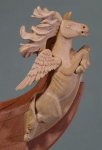
The taffrail capping pieces on both sides were completed and then I started work on the Quarter Piece blanks - fitting to the hull shape takes time - the extra meat left on these is for the relief carvings that will be added to them - the one you see in the picture is the 4th test piece and I’m sure there will be more!
-
 Trussben got a reaction from FrankWouts in HMS Pegasus 1776 by Trussben - 1:48 - Swan-class sloop based on TFFM
Thanks Chuck!
So the central coving carving had a little depth added to it as per Druxeys suggestion.
The Aft Lights have been fixed in place along with the Taffrail, then the inner counter Timbers were sanded down to match the taffrail curves and then the central portion of the capping rail was glued in place.
I made a slightly larger upper counter piece and need to finesse this into place now and decide it I want to paint it’s background black again ( when natural you can hardly see the lettering when more than a few feet away ).
Next job after this will be making up the quarter piece blanks.
-
Trussben got a reaction from FrankWouts in HMS Pegasus 1776 by Trussben - 1:48 - Swan-class sloop based on TFFM
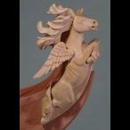
While trying to make the Quarter piece blanks, I deamed it a good idea to mark out where the Quarter badges would be so there would be no interference between them, so here is the beautiful QB that I commissioned from David Antscherl.
-
Trussben got a reaction from FrankWouts in HMS Pegasus 1776 by Trussben - 1:48 - Swan-class sloop based on TFFM
Hopefully David will agree to complete the rest of the carvings for the model.
-
Trussben got a reaction from FrankWouts in HMS Pegasus 1776 by Trussben - 1:48 - Swan-class sloop based on TFFM
Some progress
The taffrail capping pieces on both sides were completed and then I started work on the Quarter Piece blanks - fitting to the hull shape takes time - the extra meat left on these is for the relief carvings that will be added to them - the one you see in the picture is the 4th test piece and I’m sure there will be more!
-
Trussben got a reaction from FrankWouts in HMS Pegasus 1776 by Trussben - 1:48 - Swan-class sloop based on TFFM
Internal Bulwark planking completed, now to pack her up and get ready for the move.
-
Trussben got a reaction from FrankWouts in HMS Pegasus 1776 by Trussben - 1:48 - Swan-class sloop based on TFFM
Yep - from upstate NY to se NC.
-
Trussben got a reaction from FrankWouts in Sloop Speedwell 1752 by Chuck - Ketch Rigged Sloop - POF - prototype build
Looks awesome Chuck.
-
Trussben reacted to Chuck in Sloop Speedwell 1752 by Chuck - Ketch Rigged Sloop - POF - prototype build
To finish up chapter 4 and the forward platforms, the breasthooks were made. There are two of them. These are laser cut for you in two halves. Its just easier to work with them this way. I usually shape one half and lightly tack it in position. Then I shape the other half and fit it in next to it. At this point they can both be removed and joined together. Do a quick sanding to refine everything and add the bolts. The bolts are 30 lb. black line.
The lower breast hook has etched bevel lines because the side that fits against the frames needs to be beveled. Its just a start because everyone's model will be slightly different.
Lastly..to finish off this chapter I made the riding bitts. Like the fire hearth, this wont be glued in position yet. But its good to have at the ready. We will need it before framing out the rest of the forecastle deck later. So the cross beam is laser cut for you. Just clean it up and shape to suit. I just used some needle files, etc. The uprights are basically made from 5/16" x 5/16" strips. Measure against the plans and shape the tops to suit. Use the plans as a guide. Nothing earth shattering with these.
I will paint the riding bitts red above the gun deck. I used the plans to determine where that break would be. Here is what it looks like after being painted and test fit. Note the string...this is good to get in place now too. Its glued lightly to the center of the stem and then taped to the top of the stern post. It will help guide you when setting fittings along the center line. It helps a lot!!!
The fire hearth and riding bitts have been set aside for safe keeping.
Next up chapter 5 which will take care of the aft lower platforms and a few other odds and ends.
-
Trussben reacted to Chuck in Sloop Speedwell 1752 by Chuck - Ketch Rigged Sloop - POF - prototype build
The figure is off scale for the model but looks really good just with the fire hearth. So I made a mini diorama of sorts to display on my desk. I used the old second hand aged stove, LOL. Its one of Chris' figures as you would recognize.
-
 Trussben got a reaction from mtaylor in Sloop Speedwell 1752 by Chuck - Ketch Rigged Sloop - POF - prototype build
Looks awesome Chuck.
-
Trussben reacted to Chuck in Sloop Speedwell 1752 by Chuck - Ketch Rigged Sloop - POF - prototype build
Step by Step...
1. Laser cut cedar brickwork. Lightly sand the char. But not so much that you remove the etched mortar lines. Just a little. Especially on the edges of the pieces. Many have bricks etched on both sides.
apply wipe on poly when finished...this is important to seal the wood a bit.
2. Yes its bright!! But this is just the initial steps. I used a red promarker, you can see which color to add the base coat of red to all faces of the brickwork. Also note the two pieces that make up the sides have been glued together. Make sure you have the holes and pieces facing the correct direction.
3. Glue the sides to the back wall. Keep nice right angles. Also add the front piece. This is left a bit long and you will have to trim it to fit. DO NOT glue to the base. This will be done much later in the project. Much, much later.
4. Using weathering powder add some red/brown colors and dark browns to suit. It depends on how weathered you want to go with the fire hearth. You will see this at the end. Spray all the pieces lightly with some matte spray fixative when you are done.
5. This is where the magic happens. You could use white weathering powder but that would also pigment the bricks. You dont really want that. So instead use regular white flour. Brush it on and push it into the mortar lines which are made pretty deep for you. Dont go for a perfect even coverage here. Experiment a little. Push it in the cracks with your finger....pack it in there. Then brush it off the brick faces with a light touch. Experiment for the look you really want...use some additional weathering powders if you want to add soot and ash. Make it a used hearth or a relatively new one!!! Also note the frame on the base was painted black. Dont spray with fixative. The normal humidity in the air will fix the flour in position on its own. It may take a day or so depending on the weather.
6. 1/32" brass wire/rod (not included) were blackened and added as shown above.
7. The hood...laser cut from 1/64" thick boxwood. Glue the shorter back piece on the base first. It should be a at a perfect right angle vertically and centered.
8. Add the two sides. You will need to bevel the bottom to sit flush on the base.
9. Add the front piece...which is taller than the back piece. Note how the front hangs over the the front of the base just a bit. That is done on purpose. It is correct.
10. Finally add the top and front pieces. apply filler to all the cracks and sand smooth for painting. Also build the stack the same way and prepare for painting.
11. Hinges are laser board. Construct them in the sequence shown above...left to right. First add the bottom half of all the hinges. Then the hinge pins are glued along the top edge. Use 24 gauge black wire for that. To finish that up, set the top half of the hinges above the wire. An eyebolt is also added in the center. You can see that in the photos below of the finished fire hearth. There are two of them shown...
A beat up used and weathered fire hearth....and a shiny almost new hearth. Have fun with it and weather to your preferred tastes. LOL
NOTE....the hearth is NOT glued to the base yet. And the stack is NOT glued to the hood yet. It is best to keep them separate for now.
-
Trussben reacted to Chuck in Sloop Speedwell 1752 by Chuck - Ketch Rigged Sloop - POF - prototype build
The next step was to create the bulkhead on the lower platform. This was laser cut. All I had to do was cut some 1/8" x 1/8" strips to simulate the vertical beams. I just cut them to length and glued them on. Now this piece may not actually fit your model perfectly. There are just too many variables. It all depends on where you placed that first platform beam. It also depends on how you faired the interior of the hull. But I sure it could be tweaked in most instances. If you had to, you could use this as a starting point template to make another. It isnt very difficult to do.
This is a picture of the bulkhead glued in position. It is glued on the forward side of that first platform beam. The templates are there to help me during the next step. I will be adding the carlings and ledges. They can be taken right from these templates which are on the plans.
Here is a photo of the ledges and carlings completed. These will support the scuttle lids once planking is finished. I plan on planking the entire platforms. I think it will make creating the various cabins a lot easier.
Planking is underway with 5/16" x 3/64" cedar strips. I am not too concerned about getting up close to the sides of the hull. Depending on how fairing went, this could sometimes lead to a weird shape along the edge of the platform. So I concentrated on making a nice shape with the outer edge of the platform deck planking since the sides of the hull inboard will not be planked. I am getting close to the side though and creating a consistent shape port and starboard. It will be impossible to see the sides of this planking when done. Once I get this done I will add the metal work (eyebolts with rings) for those scuttle lids. Then its onto the two aft platforms which are done in a very similar way. Also note the two cut-outs for the legs of the riding bitts. The planks were cut so I could slip the riding bits down into those slots...hopefully!!!
Somebody asked to see a wider shot of the hull with the depth gauge in position. So here is a picture of the hull all dusty after finishing the planking on those forward platforms. Dont hesitate to ask me any questions.
-
Trussben reacted to Chuck in Sloop Speedwell 1752 by Chuck - Ketch Rigged Sloop - POF - prototype build
I wish I had a foolproof method. I faced the same issues. Multiple scrap pieces and do-overs. The only advice I can give is to not settle and make a new deck beam when one doesnt fit. The plans are pretty accurate but everyone will fair the inside of the hull differently so they are always going to be custom fit.
Honestly I just eye-balled the length making them slightly longer to start and then slowly sanded the ends until they fit. Each pass I made slight adjustments to the angles on each end. If I over did it…then I tossed it and started again. Thats what ship modeling is all about…at least for me.
You guys didnt see my many do-overs, LOL.
If there is any silver lining…I will be completely planking these lower platforms. So the beams wont be seen anyway.