
HOLIDAY DONATION DRIVE - SUPPORT MSW - DO YOUR PART TO KEEP THIS GREAT FORUM GOING! (Only 20 donations so far - C'mon guys!)
×


mbp521
-
Posts
1,002 -
Joined
-
Last visited
Content Type
Profiles
Forums
Gallery
Events
Everything posted by mbp521
-
 Thanks MCB. There is usually a lot of trial and error with new techniques, this one just happened to be a happy accident that worked out perfectly. -Brian
 -
Thanks Pat. I was a little nervous at first about tackling a scratch build, but the more I get into it, the more I’m settling into it. -Brian
-
Thank you Gary. I may have stumbled on a good submission for the “Model Tips and Tricks” discussion. -Brian
-
Vaddoc, thank you for the kind words. This is the first build that I have used styrene on extensively and it is a great product for those hard to bend pieces that will be painted. I did use is a little bit on my last build, but nothing significant (only made a few downspouts with it). I definitely foresee me using a lot more of it on this build though. -Brian
-
Thank you Moab. No worries, feel free to repeat away, it never gets old. Definitely makes me feel better knowing that my work is helpful and inspiring to others. -Brian
-
Thanks Keith. I still have a little more plumbing to go, but I am not able to install it until I get the boilers in place, which require me to finish the wiring, and so on. It's almost a shame that very little of this will be seen, but it sure is fun building it. -Brian
-
Wefalk, The plastic just naturally formed the domed head when the heat was applied. I was trying to shape my plumbing pieces when I discovered this and figured it would work perfectly for my rivet heads. It was really pretty easy. The best part about this is that none of the rods are glued into place, but with the expansion from the heat they formed into the holes and stuck pretty good. The zero tolerance holes made them pretty snug to begin with. I wish I would have discovered this earlier, I would have used this method on the construction of my paddle wheel frames. -Brian
-
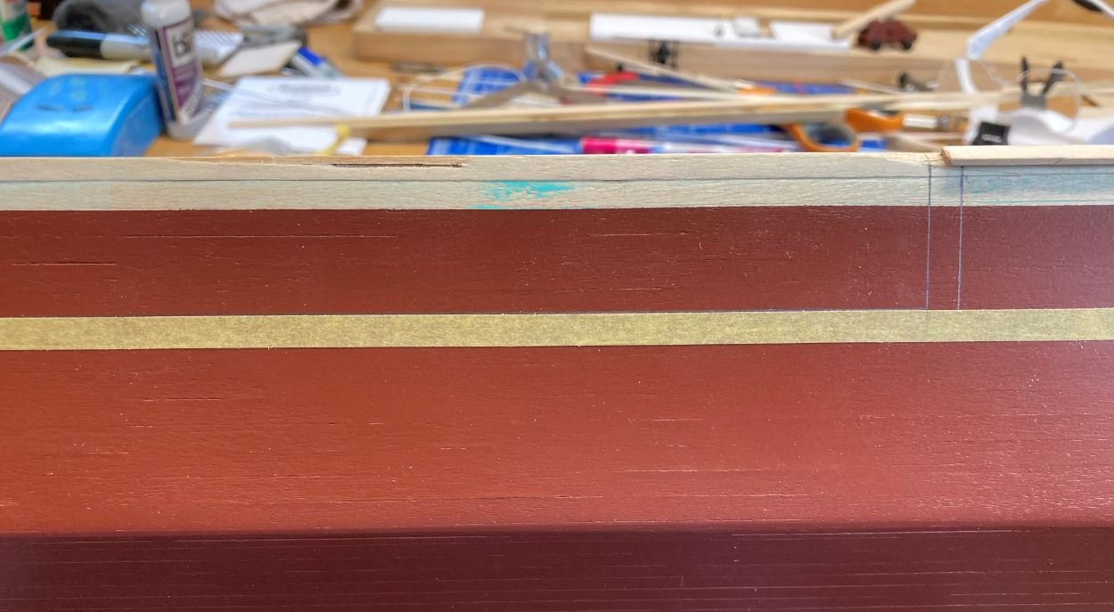
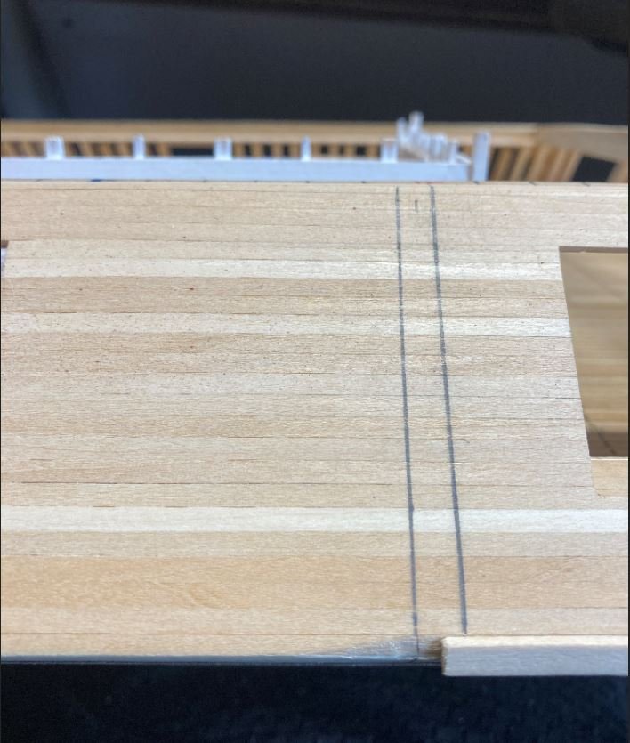
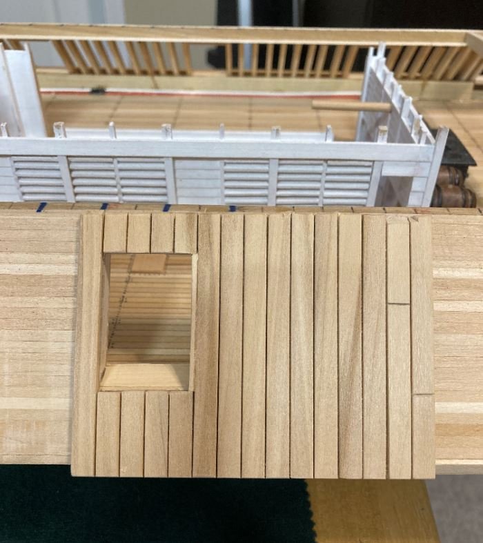
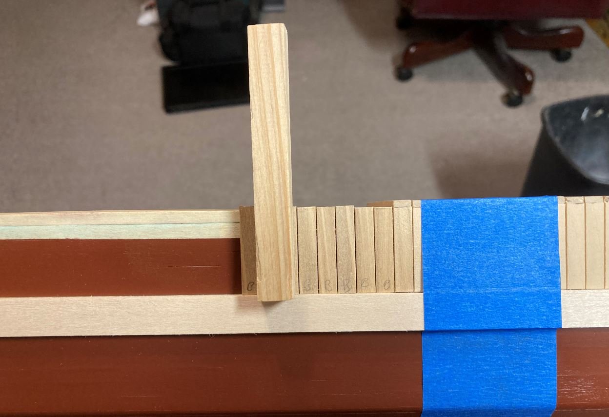
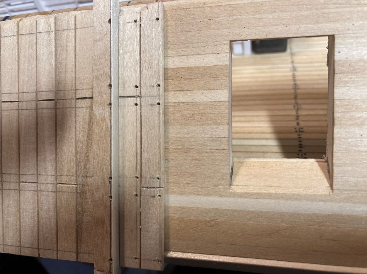
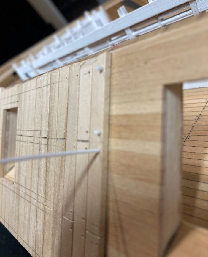
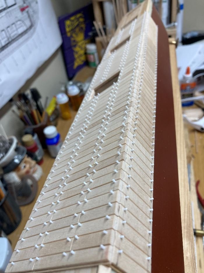
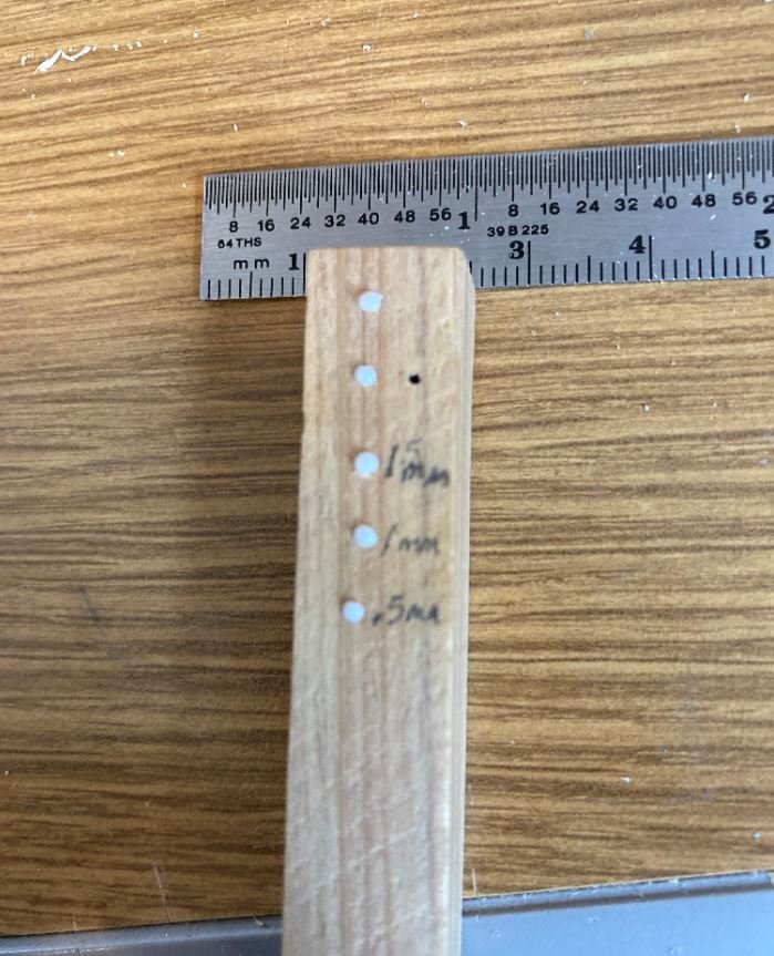
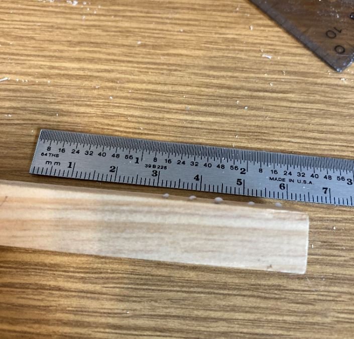
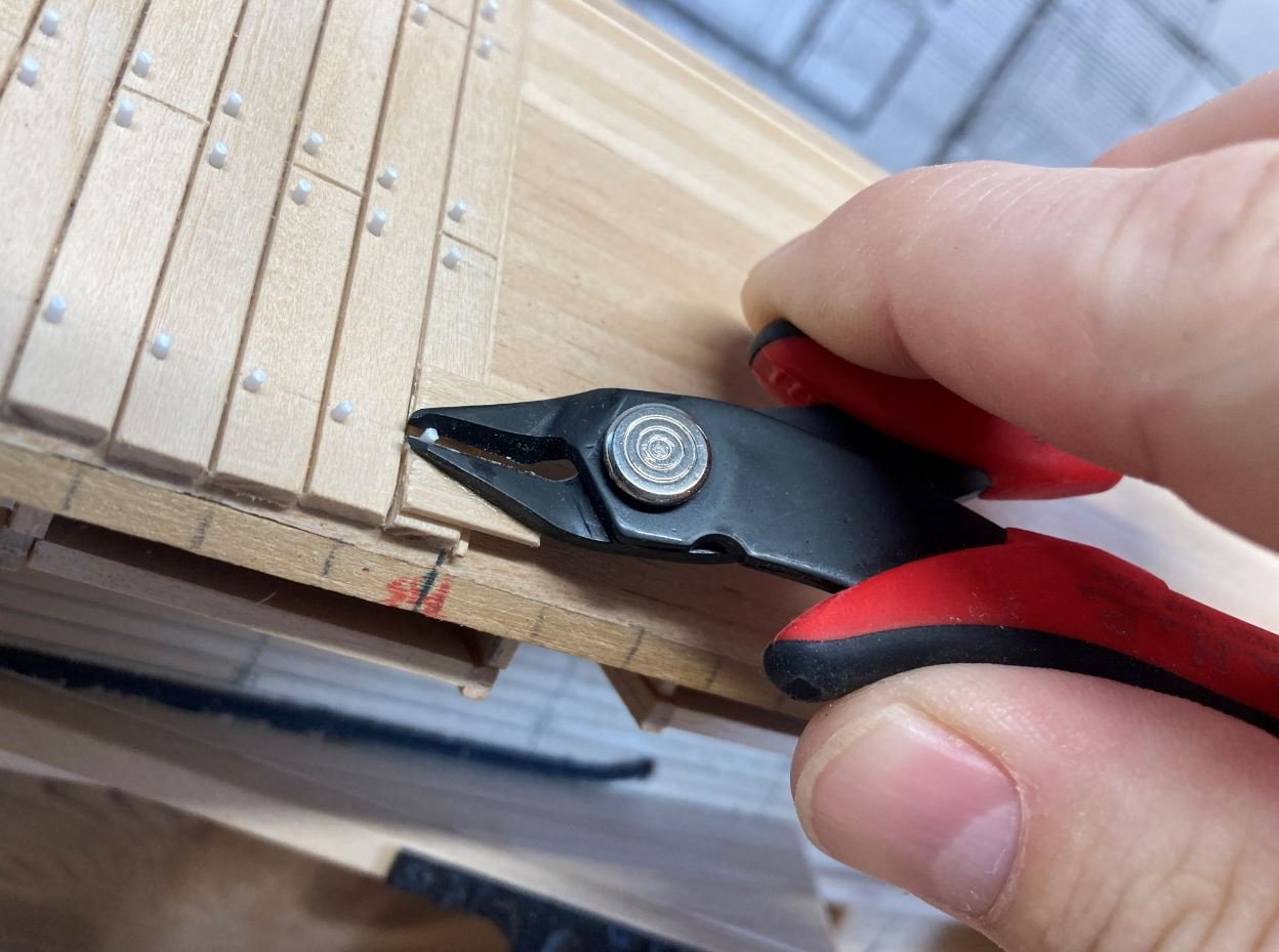
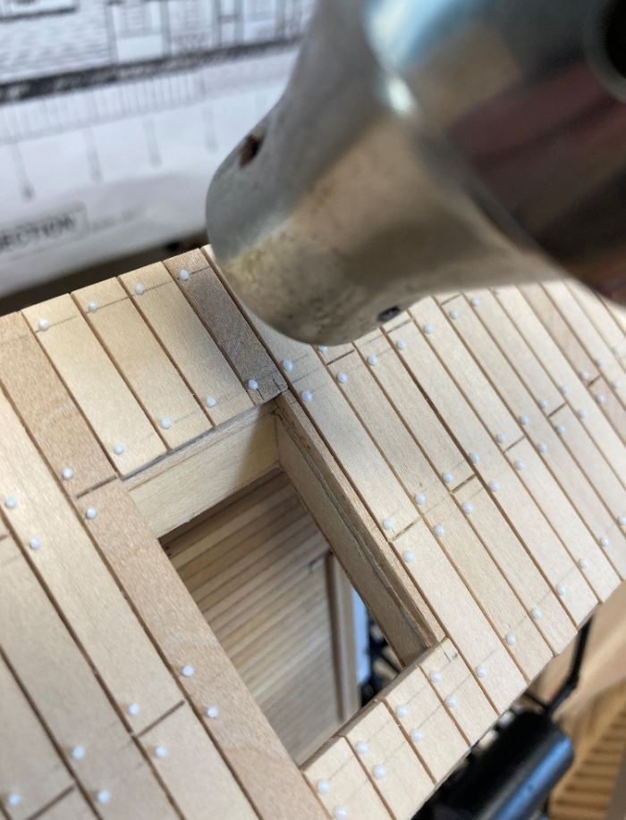
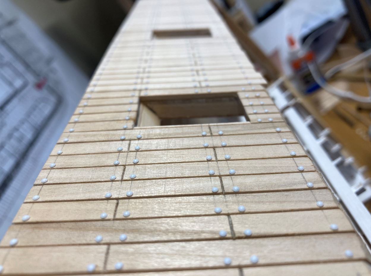
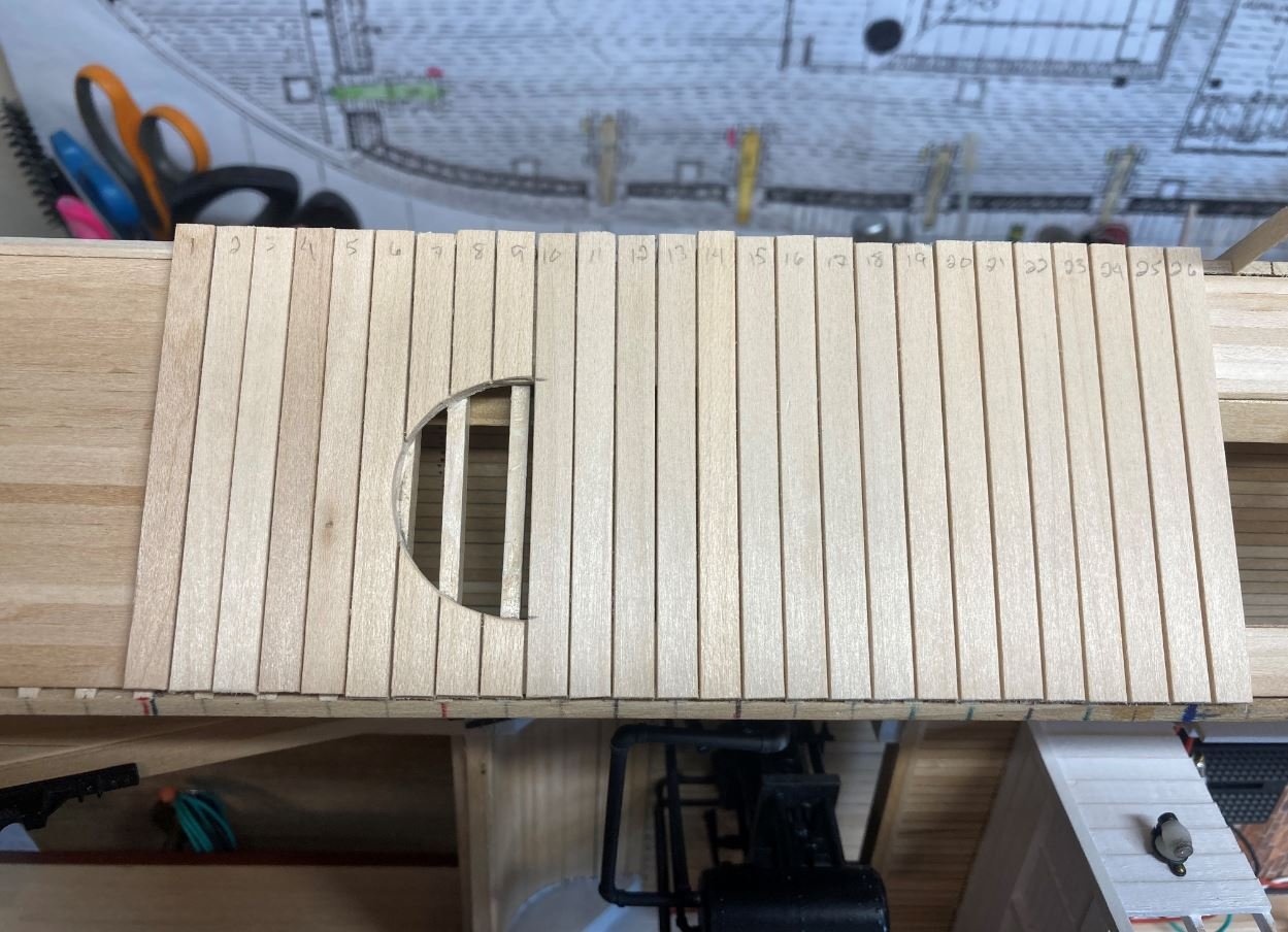
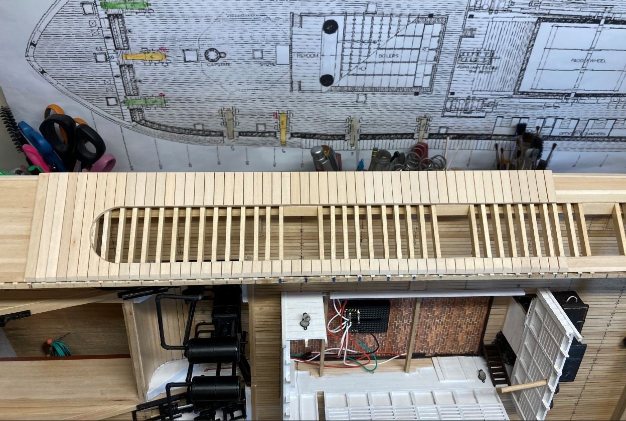
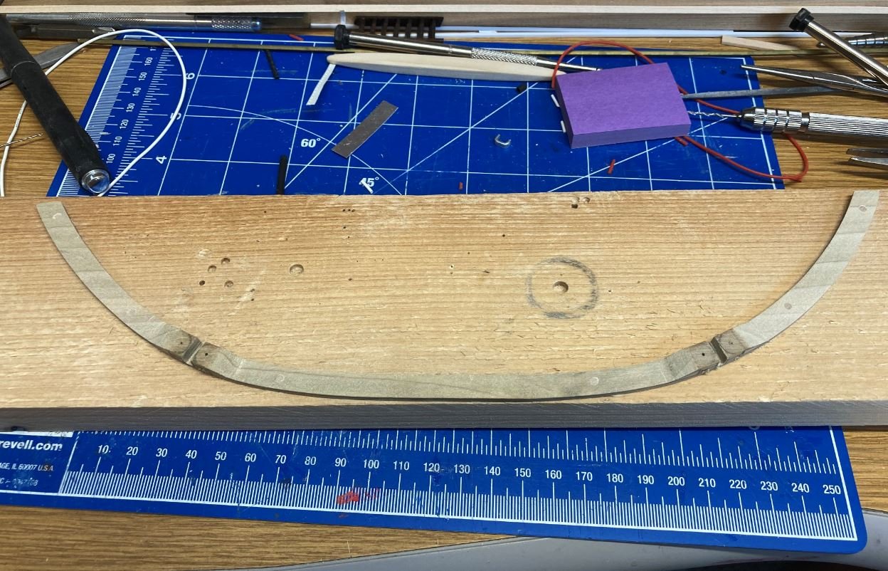
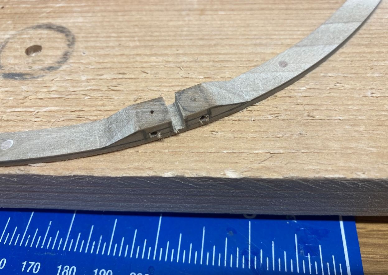
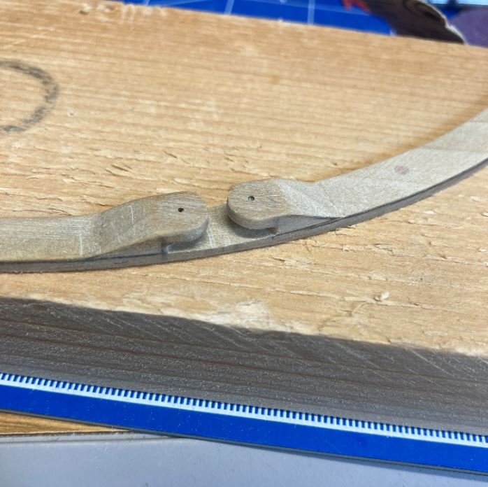
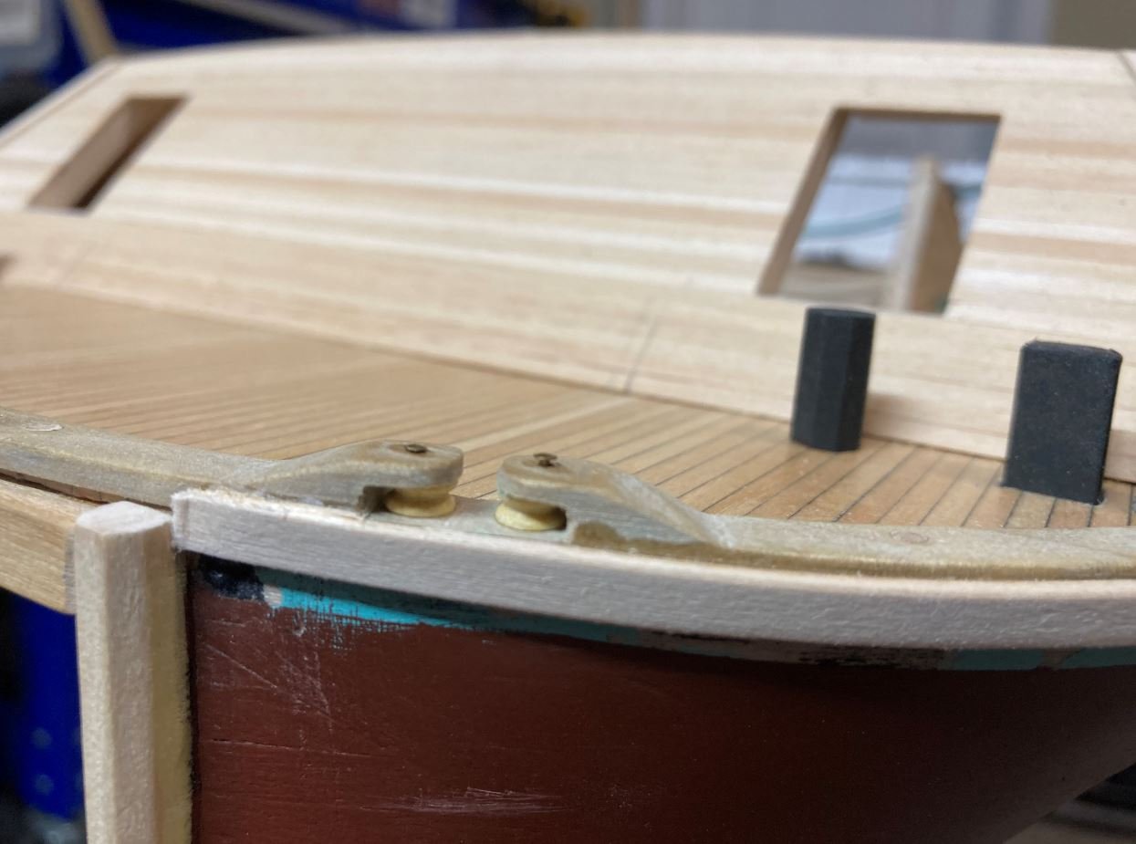
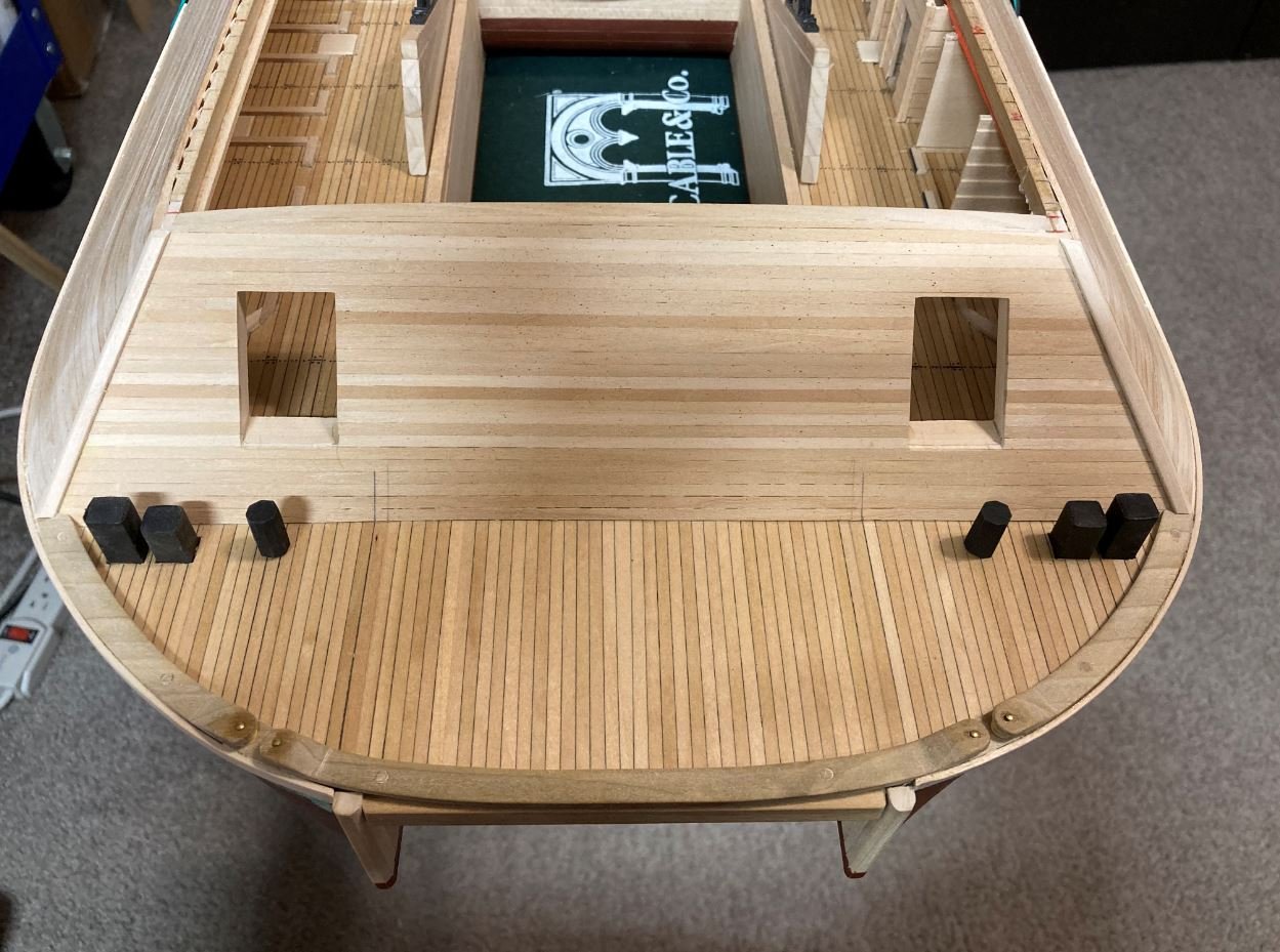
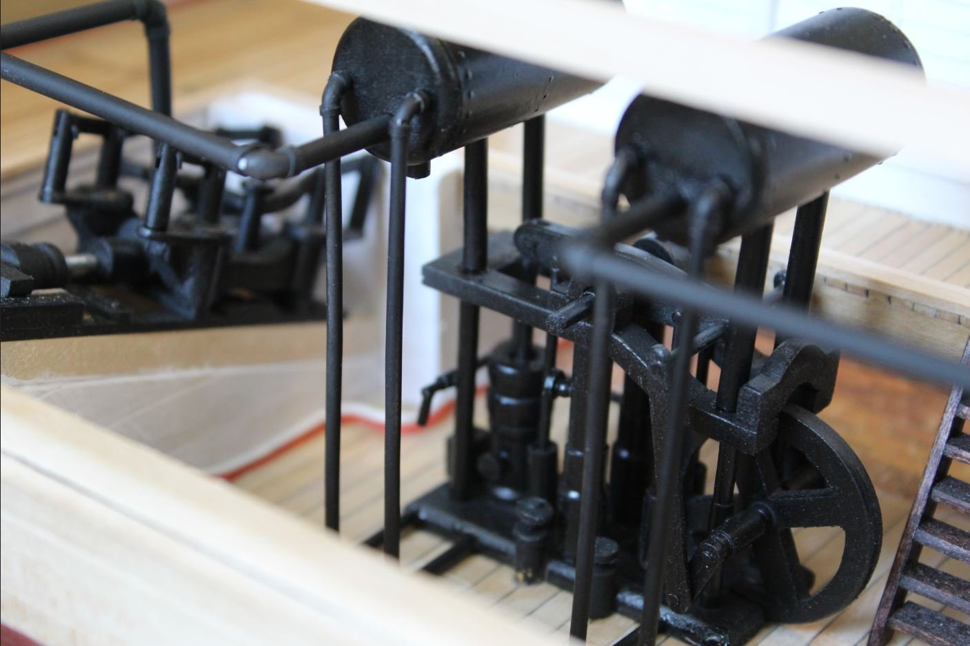
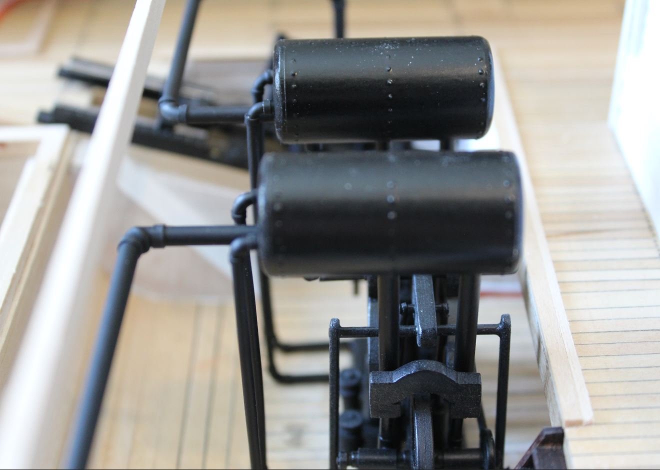
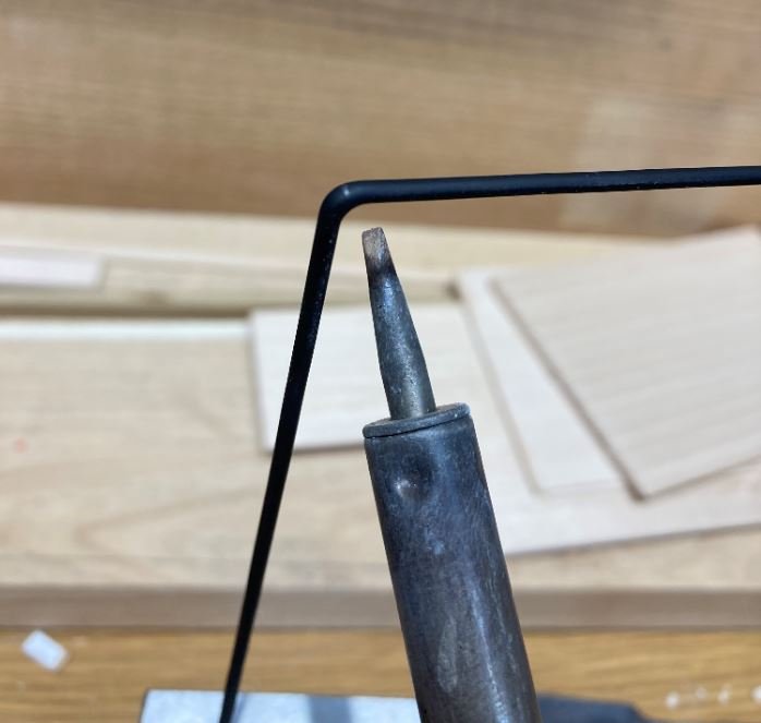
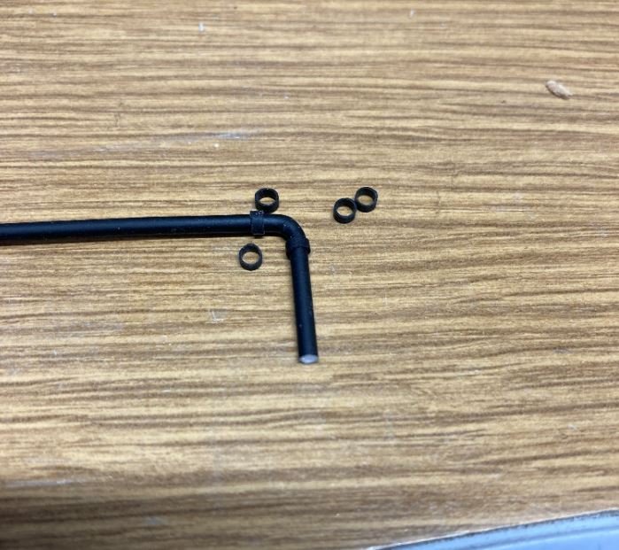
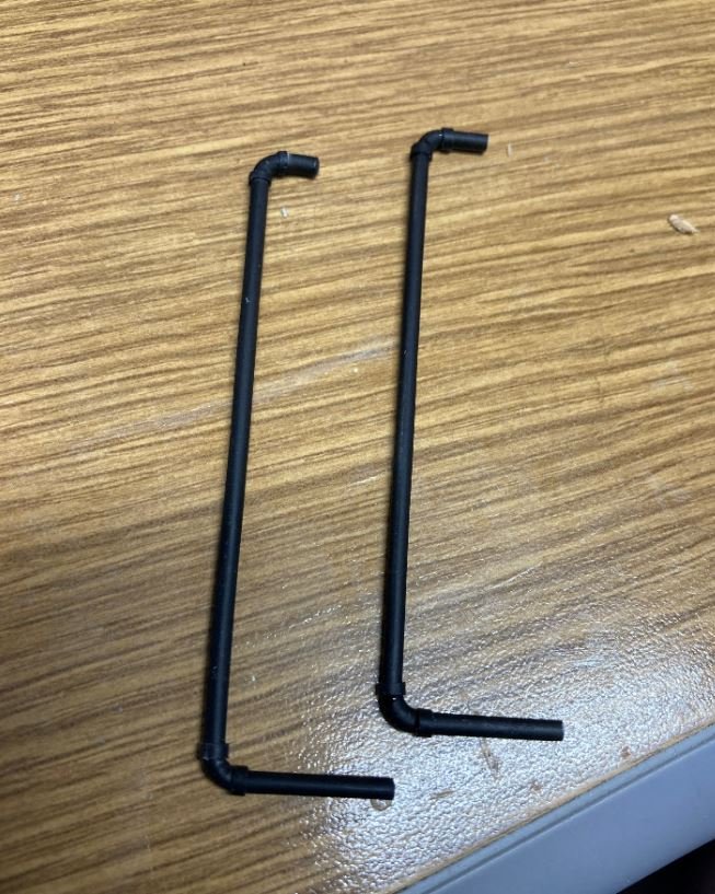
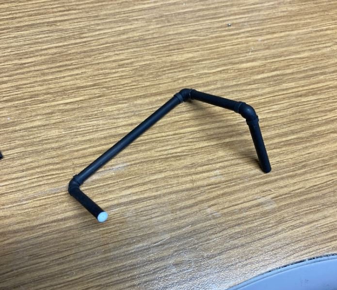
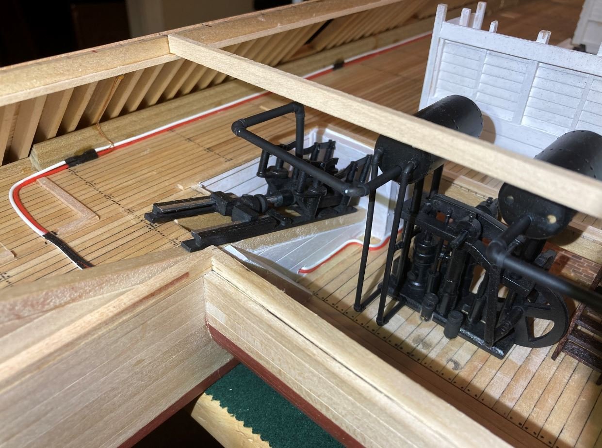
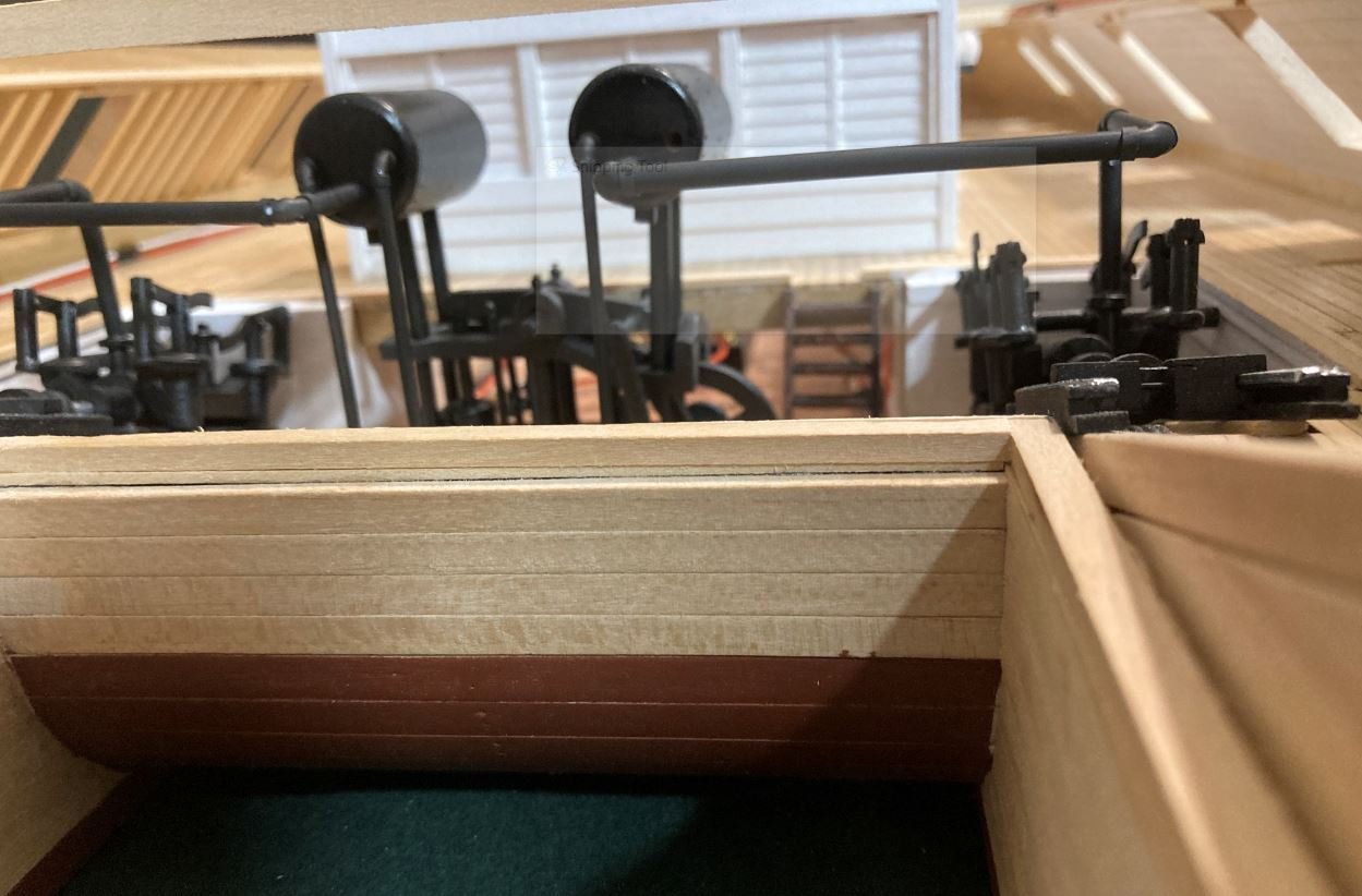
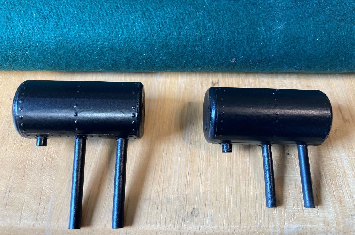
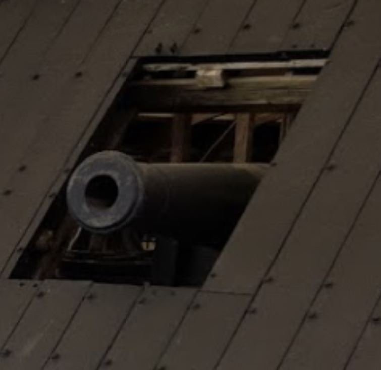
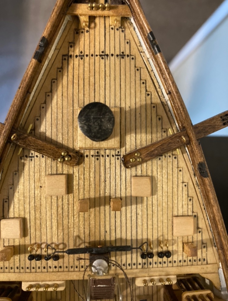
Hello again everyone, Time for another update. Things have slowed down a bit since the weather has turned nice. Lot's of projects around the the property that need tending to before the Texas summer heat sets in. With this update I was able to finish work on the aft bulwarks. I fashioned these out of one piece of poplar and carved out the fairleads in pretty much the same way that I did the forward ones. Roughed out shape and pinned to a board to make it easier to work with. Fairleads starting to take shape. Final shaping and sanding. Bulwarks installed on the hull and rollers in place (I did go back and set that right pin flush. I just didn't notice it until after the picture was taken). and the finished install. Next it was on to the preheaters and some of the plumbing. I built the preheaters the same way that I did the boilers. These were made from a 3/4" dowel that I wrapped with aluminum tape with imprinted rivets. These did not survive the salvage so it was pretty much guesswork as to how they actually looked. I used the example from Adam L. Kane's The Western River Steamboat book as my template for these features along with the plumbing diagram in the HSR. The finished preheaters. For the plumbing I used different size styrene rods. To shape them I held the rods over a soldering iron to soften them up. Then I just bent them to shape. I used small rings of heat shrink to simulate the fitting collars to give it a little extra detail. Once these were all built up, they were installed. I temporarily installed a roof beam to line up the pipes where I will eventually place the pipe hangers. Then it was on to the armor casemate plating on the port and starboard sides. According to the HSR, the armor plating was not only on the side casemates, but also extended 55" down the hull to protect it below the waterline. I'm not sure why, but this lower armor did not make to the display in Vicksburg. Marking the 55" line on the hull (this equated to 29mm) below the knuckle. Since the actual plates were shiplap, they did not butt up against each other and there was a slight gap in between each plate. I made up a little jig with a .5mm shim to give it the equal spacing. Next it was on to the upper armor plates. On the actual boat, the armor plates did not line up exactly with the gun ports so they placed a small filler piece on the sides of the gun port frame to give it full protection. Once the plates were installed, I made up another jig to line up all of the bolt/rivet holes that held the plates in place. Then it was time to experiment. I wasn't exactly sure how I was going to simulate the bolts/rivets until I got to playing around with the styrene on the plumbing. Before I used the soldering gun to soften the plastic I tried my heat gun. This spread the heat over too big of an area, but on my attempt I noticed that the heat gun made a nice mushroomed head on the end of the styrene rod. The light then came on and I though, hey what a perfect way to make rivet heads. So I proceeded to experiment with some smaller styrene rod. The bolts/rivets holding the plates in place were approximately 3/4" which translated to .040". So I drilled a piece of scrap wood with a .040" bit, placed a piece of styrene rod in the hole and heated the end of it. I experimented with several lengths extending out of the wood in order to get the right size head on the bolt/rivet and finally settled on the 1mm length. I think this worked perfectly. Once I had found the length that I liked, it was on to filling all the holes. Once the holes were all filled, I went back a trimmed them all to equal lengths. I glued a 1mm strip of scrap to each jaw of my flush cut pliers and trimmed the excess off of each rod. Once they were all trimmed, next came the heat. And viola, 540 bolts/rivets installed. Once the starboard side was complete, it was on to the port side. This side was a little more challenging, since I had to cut out around the viewport. Still no big deal, just a little extra patience and that side was done to. Now all I have left is to mark and drill all the holes and finish this side. Well, that is all for now. I'm going to finish up on the armor plating on the port side and start on the forward plates. Until next time, thank you all for looking, the kind comments and likes. Stay safe and well. -Brian
- 739 replies
-
- 19
-

-
George, This was one of the more difficult rails to build and after several attempts at trying to bend them I gave up and carved mine out. Here is how it came out. Forgive my crudeness of how it looks. I started this ship about eight years ago and it was only my second full build. That’s mainly the reason I shelved it until I gained more experience. As for the deck, I just left the basswood strips natural with a coat of clear satin varnish. This I figured would give it the look of freshly holy stoned wood (with a little sheen of course). Not quite accurate, but this is the method that I use in almost all of my builds. Hope this helps. -Brian
- 602 replies
-
- 2
-
-
- Flying Fish
- Model Shipways
- (and 2 more)
-
George, nice job on the stern bulwarks in getting them shaped. This was an area that I struggled with on my build, but you nailed it on the first try. For your question about the stanctions, I am no expert on these but I believe they were an extension of the frames. If you take a look at Ed T’s build log on the extreme clipper Young American, while be it this was a William Webb construction, not a Don McKay ship, their construction was similar, you’ll see that about every other frame was extended above deck to for the stanctions. This is a great build along with an outstanding tutorial that provides a wealth of info on extreme clipper construction. Keep up the good work. -Brian
-
George, Really looking good so far. I’m right there with you on making adjustments. There hasn’t been a single one of my builds where some form of “tweaking” didn’t have to be done. All part of the build though. You will definitely need to soak and steam those aft boards around the stern. I remember having several snap or split on me even after a good soaking before I got them to lay down right. -Brian
- 602 replies
-
- 2
-
-
- Flying Fish
- Model Shipways
- (and 2 more)
-
Eric, I’m liking the the later versions with the more muted colors and weathering. Just for curiosity (and conversation sake), and since this is a bit out of my element, were the symbols and colors on the shields used to represent a certain clan much like the tartan plaids of the Scottish kilts, or were they just representative of each individuals personal preference? If they were the latter, then you could use several different designs and colors on them (not to create more work for you) just food for though. The site Steven posted shows that The Vikings were believers in that colors represented certain things, and each shield owner could have put his/her personal touches on theirs to tell their own story. Just random thoughts. -Brian
-
For those who may be interested, I just ran across this fantastic video online. It was filmed back in 2019 and it is a presentation given by Edwin C. Bearss, author of Hardluck Ironclad, on his involvement of the USS Cairo recovery. He has a slide presentation to go along with his talk that has numerous pictures of the recovery that aren't widely published. The video is a little long, but very interesting. https://www.c-span.org/video/?457702-6/recovering-uss-cairo# -Brian
-
I have to agree with you. I personally think that those guys were smarter than the designers now days in the fact that they didn’t have the technology that designers now use. It was pure mental and mathematics on paper. They didn’t have that luxury of using the computer do their thinking for them. It did take guts and know how (along with some trial and error) to produce these beautiful ships. Total respect for those guys. -Brian
- 602 replies
-
- 1
-
-
- Flying Fish
- Model Shipways
- (and 2 more)
-
George, Looks like photos came in just fine. I love the sleek, graceful lines of these Clippers, it’s no wonder how they could just cut through the water like they did. Donald McKay was a true artisan and a master of the extreme clipper design. Even though you are still in the early stages of the build she is really coming along nicely. Good idea to paint the hull before planking the deck. It keeps from having to clean up any overspray and saves on the precious Tamiya tape. -Brian
- 602 replies
-
- 1
-
-
- Flying Fish
- Model Shipways
- (and 2 more)
-
Gerhard, Its been a while since your last update. Just checking to see if this project is still coming together. -Brian
-
gak1965, I received my copy of Hardluck Ironclad the other day and finished it in two days. What a wonderful read! There were a lot of great details in there that I had no idea had happened. It's a shame that the reconstruction process got mired down in political red tape for so long. After wasting away for nearly 13 years at Ingalls Shipyard it's amazing that there was enough of the wood fabric left to piece together for display. Who knows what it would have looked like had they started the restoration process right after her recovery. -Brian
-
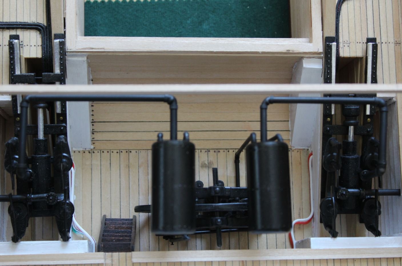
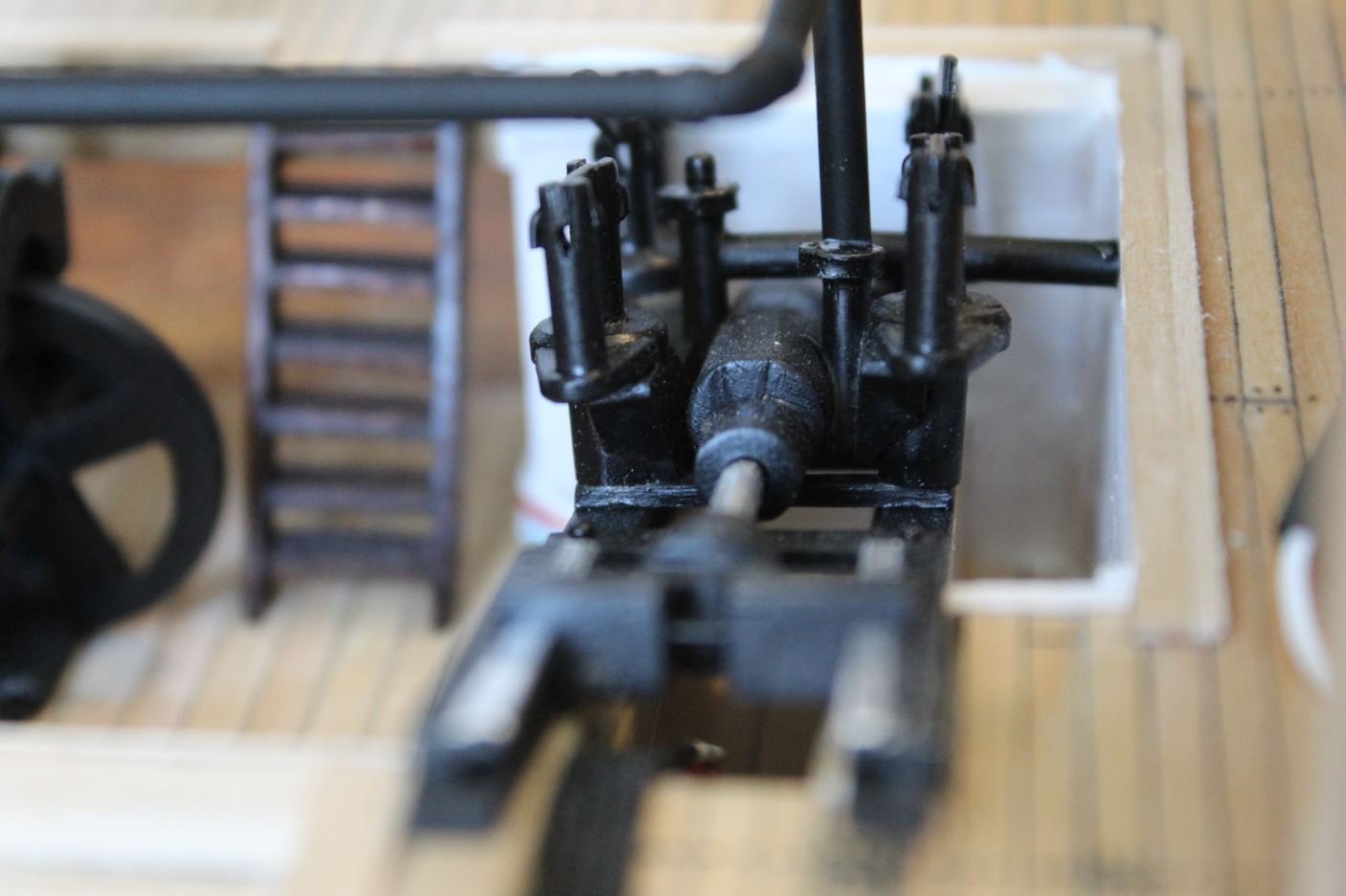
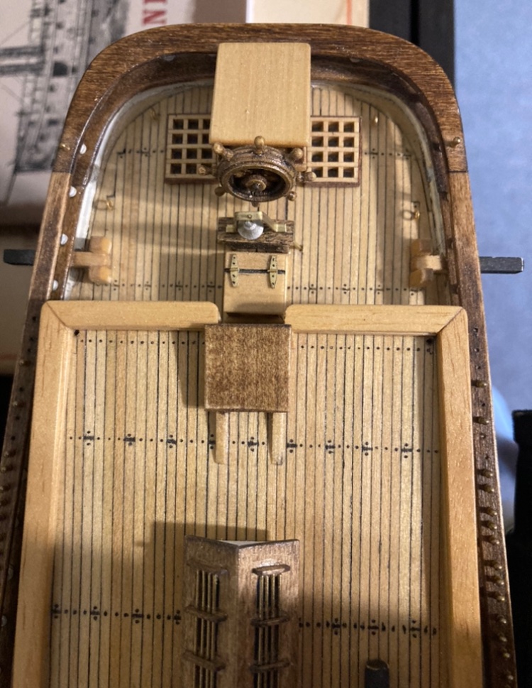
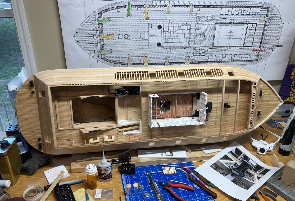
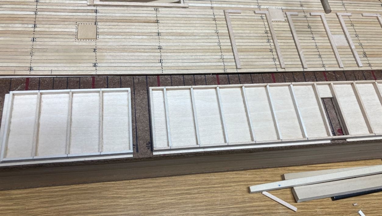
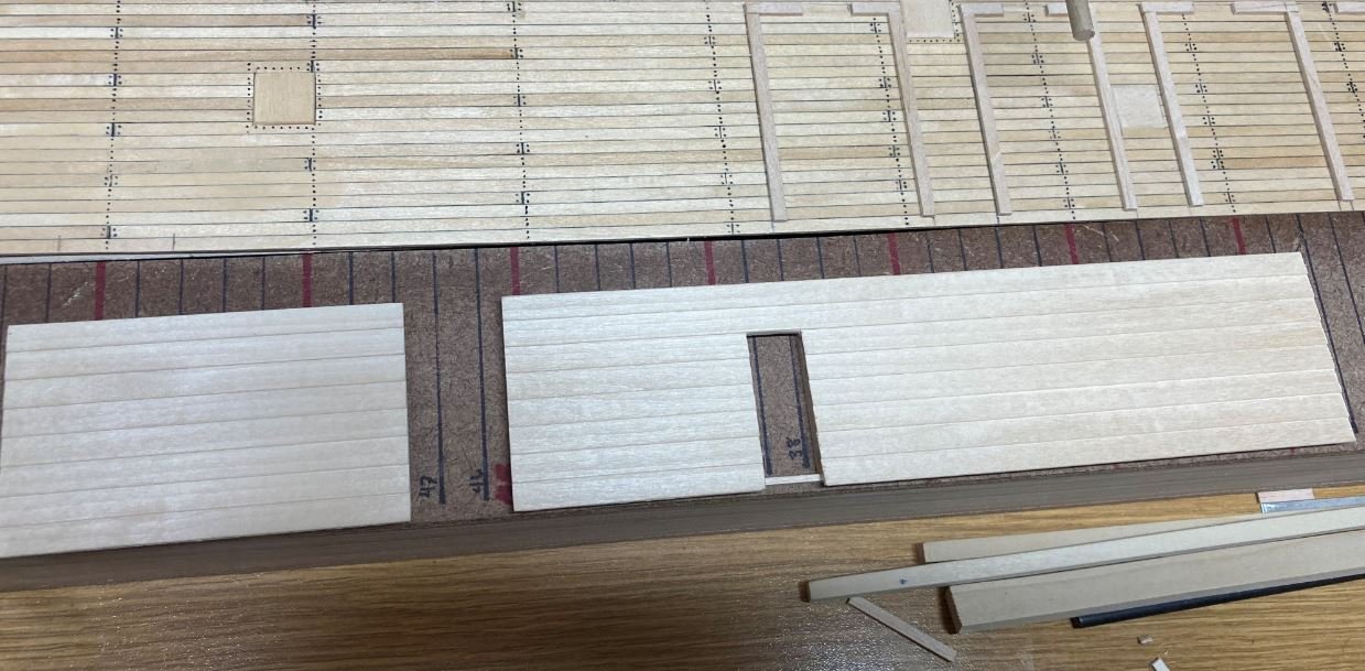
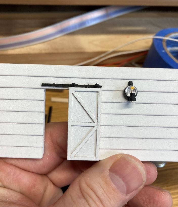
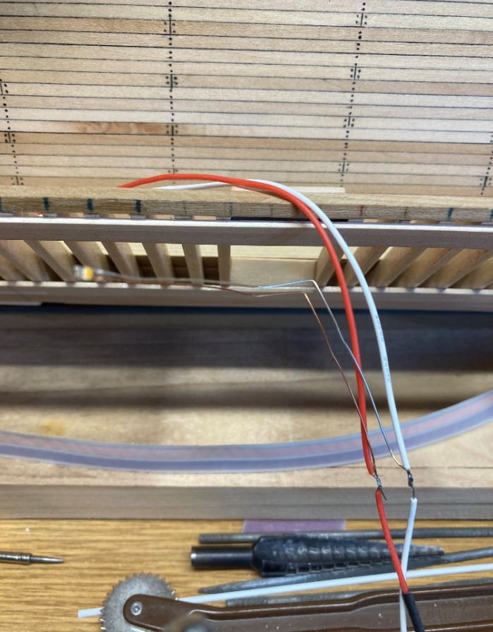
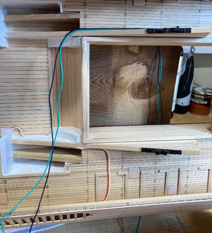
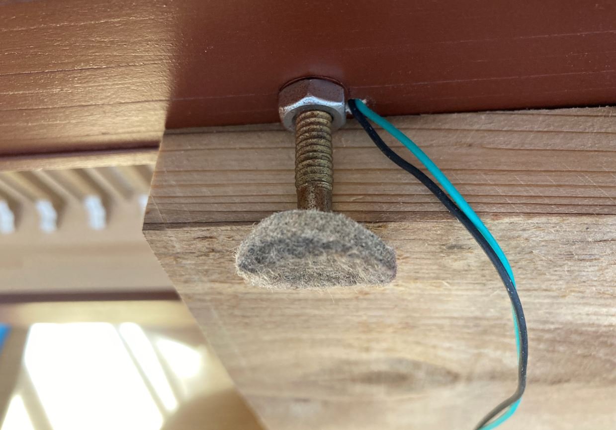
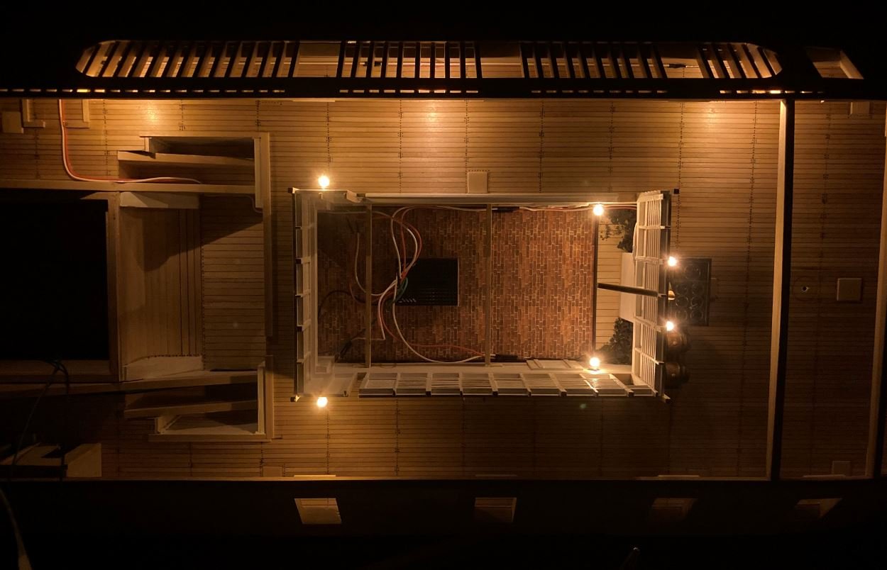
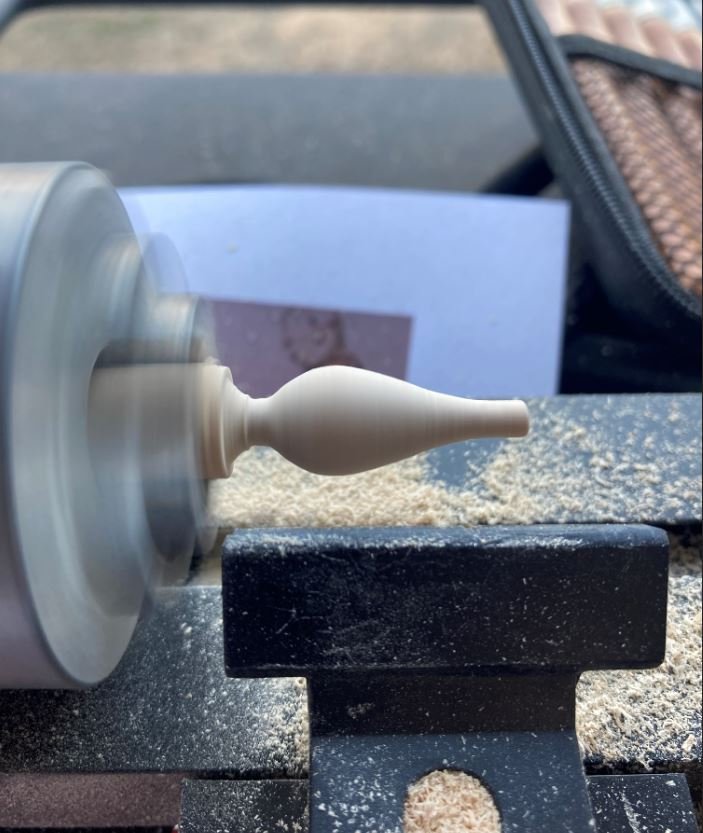
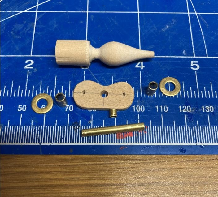
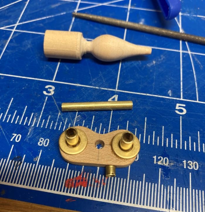
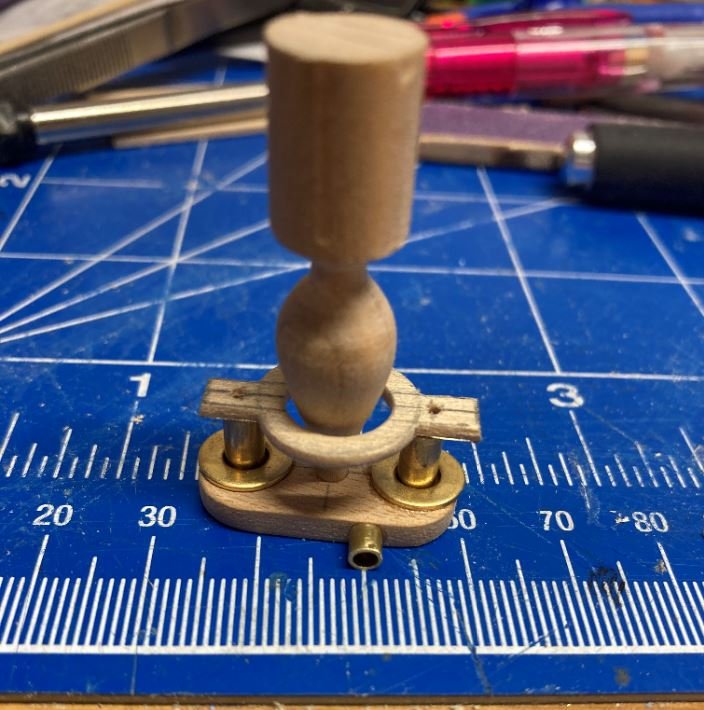
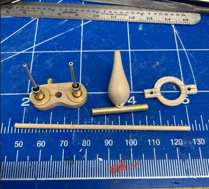
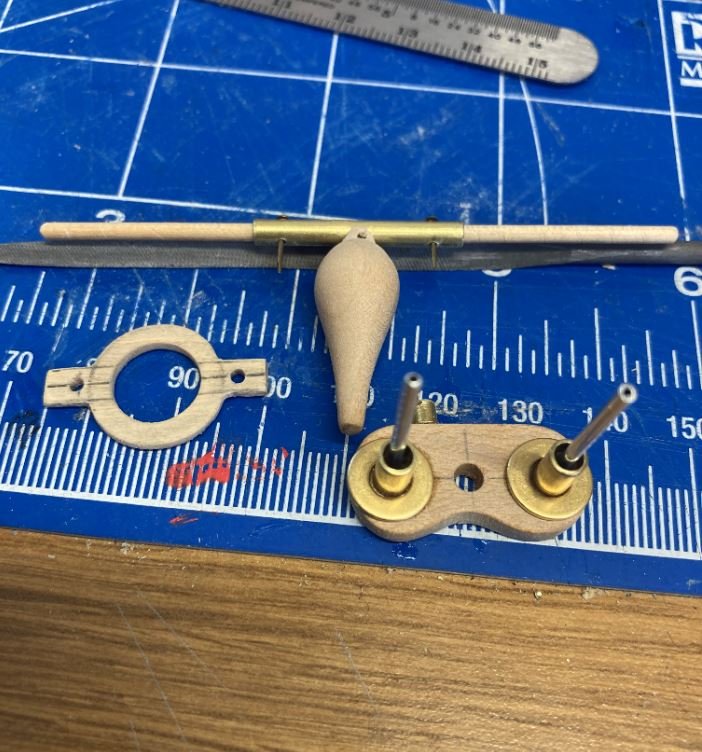
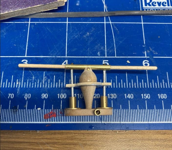
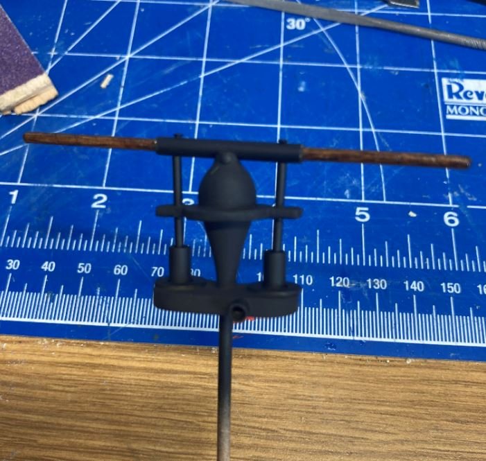
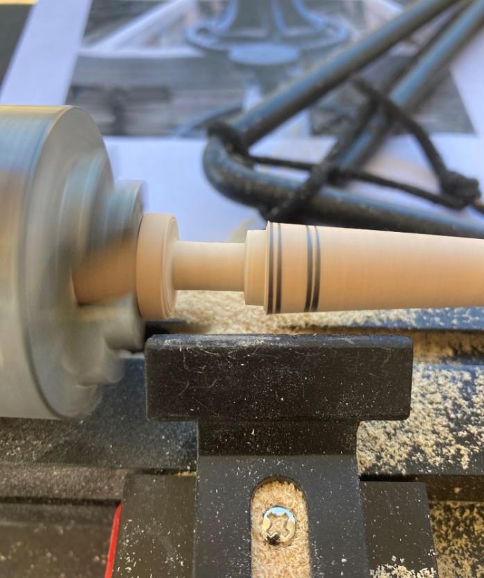
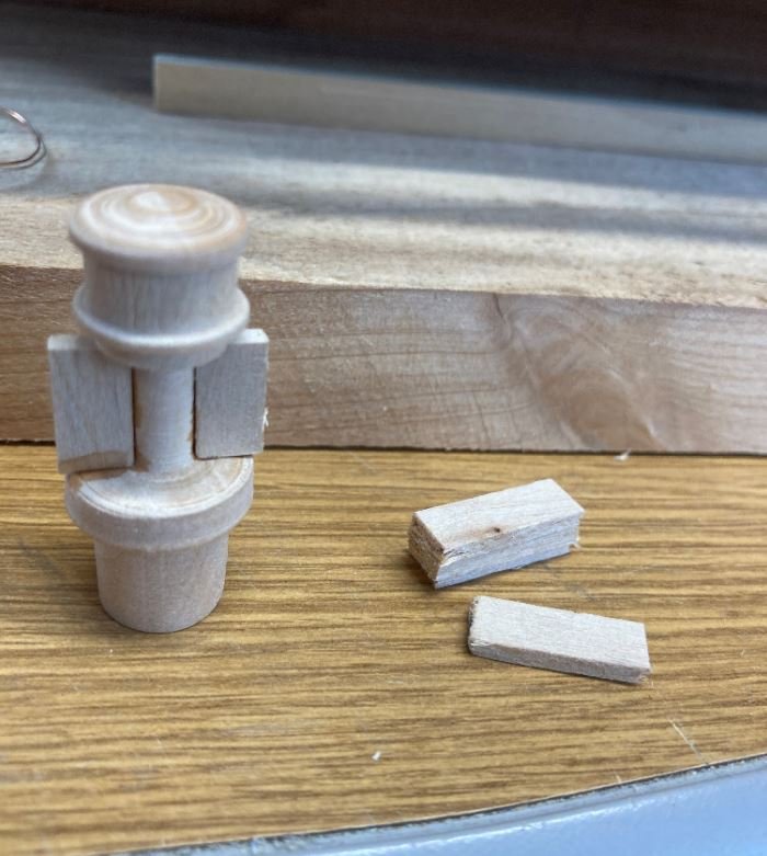
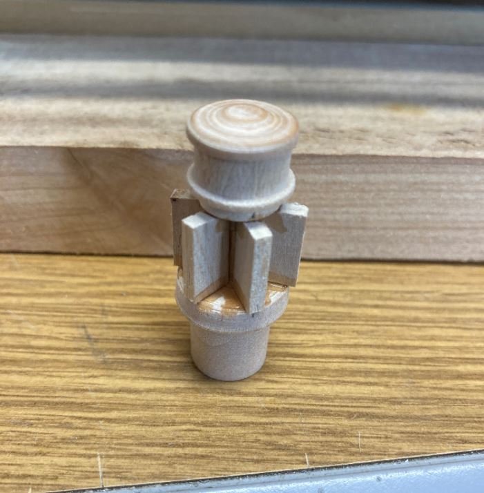
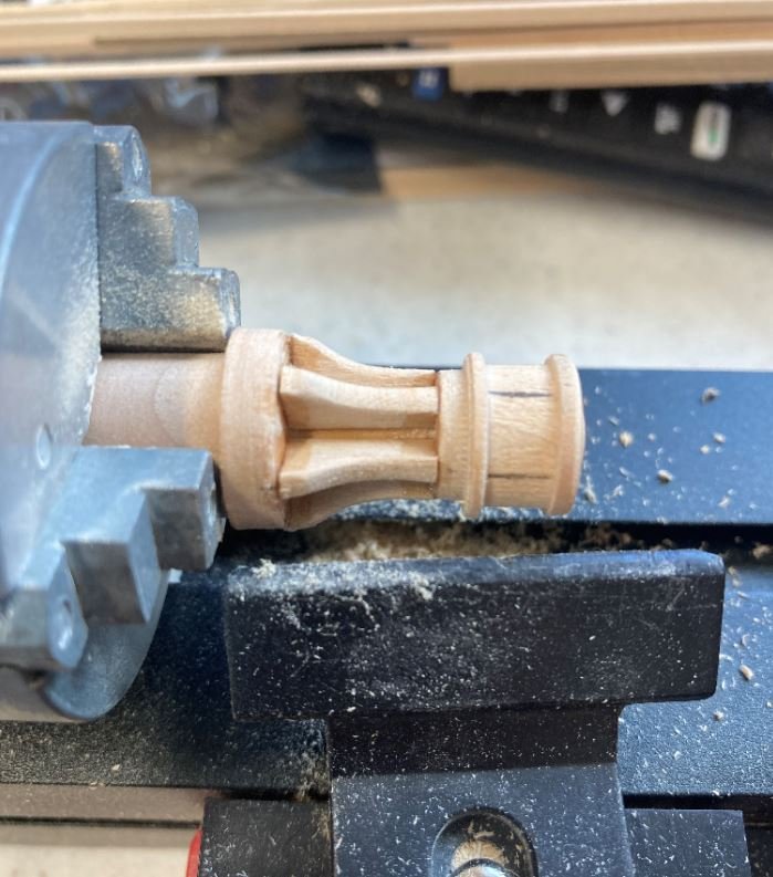
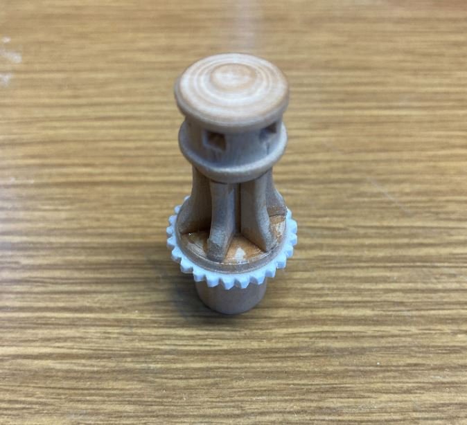
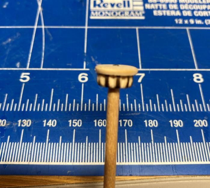
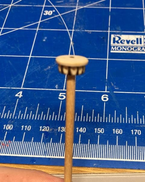
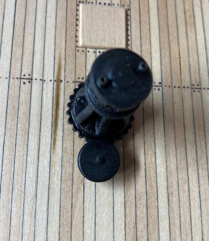
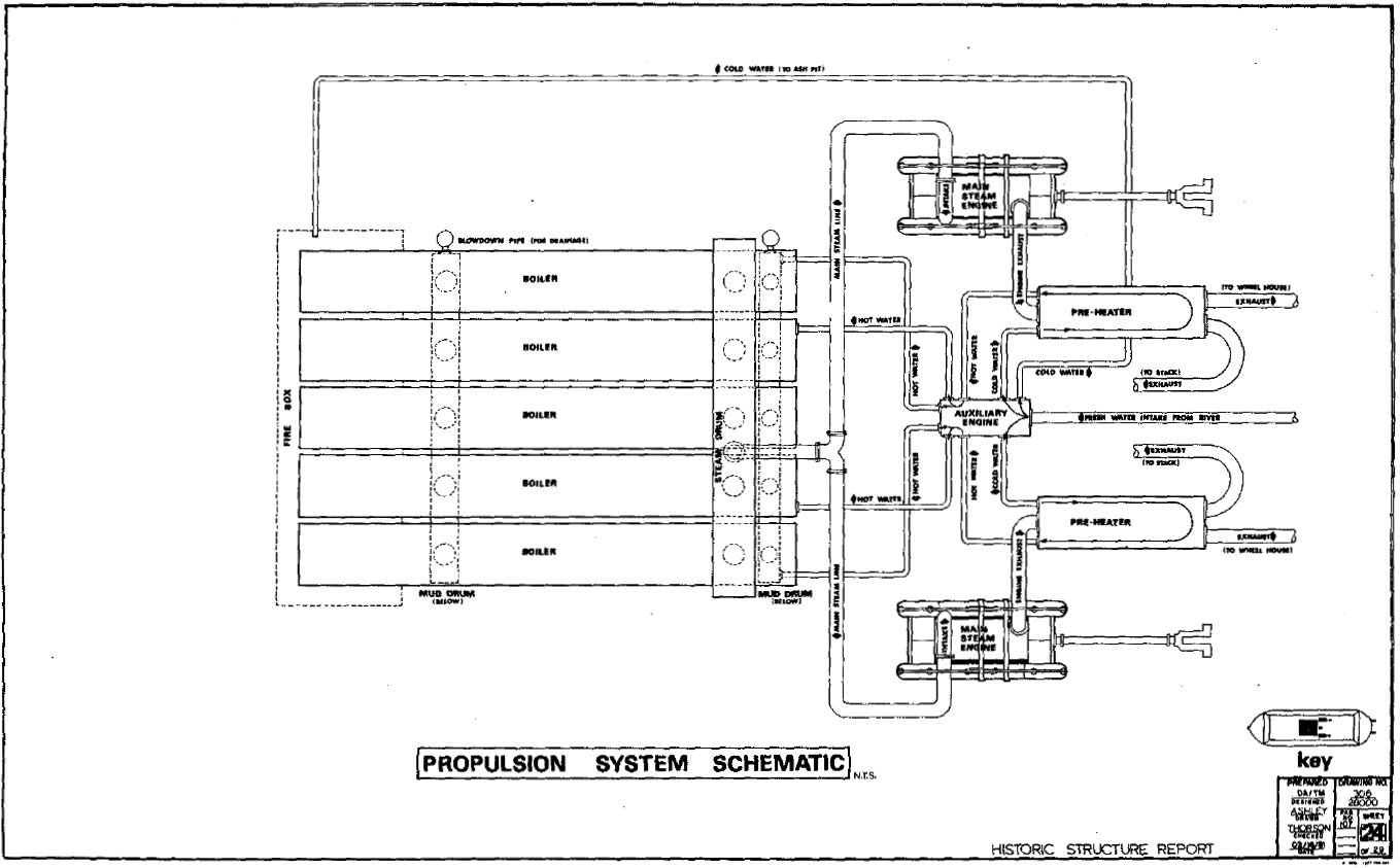
Hello again everyone. Time for another quick update. More progress was made this week on the some of the machinery and other deck features. I started this week off with the bilge pump. First I turned down the pump body. Next I cut out the base and the brass features. These consisted of the pump tubes and flanges as well as the portion. Piecing the lower portions together. Next I cut out the center support and test fit it for alignment with the sucker rods. The sucker rods were then installed, the pump body was shaped to receive the pump handle assembly. Pump handle installed. Then everything was put into place and glued together. Finally a coat of black paint, some stain for the handle and the whole thing coated with satin varnish. Next assembly was the capstan. Again, I turned the main body of the assembly down on the lathe. Next I installed the drum "fins" of the capstan. I placed the assembly back in the lathe to shape the drum. Next I carved out the holes for the capstan bars, then assembled the bottom gear. This was done by using 1/16"x 1/16" styrene that I filed the grooves in. I then heated the gear then wrapped and glued it in place. The heating wasn't really necessary, I just didn't want to risk the plastic snapping and have to go back and refile all those teeth. Then came the small drive gear. Same concept on the gear teeth, only I used a wooden bead for the base, filed the teeth then capped it off with a thin piece of scrap wood. Then all the pieces painted black and varnished and temp installed in position. Next on the assembly list were the interior walls that close off the engine room and provide a sound barrier. There is no documentation on this partition other than some of the lateral section drawings in the HSR. Most of this section was destroyed during the recovery when the cable slings cut through the hull and casemates. This is also the area where the "Doctor" pump was located. I'm guessing that when the lifting cable cut through, it ripped the "Doctor" from its mounts, it fell through the opening, then settled to the bottom of the river where it was buried in the mud and silt, never to be found. I figured that I would again take my builders liberties and add them since there seems to be some resemblance of them in the HSR. The basic structures. Door and lighting installed. I didn't take too many pictures of these since they were pretty much straight forward. After creating a bunch of sawdust, I wanted to take a break from it and focus on more of the lighting and wiring. I didn't want to get too far ahead of myself and not have room enough to get my hands in the deck area to place the wiring and LED's. Just a few quick shots of the wires being installed. All of the LED's will be run with the red and white wiring and the supply wiring is the black and green. At first I was going to keep all of the wiring confined to the boat, but I couldn't come up with a good way to store the battery and actuate the lighting like I did on my Chaperon. So instead I decided that I would have the switch and battery installed in the base. This way once I build the display case I would have to keep removing the glass to show the lighting. So I ran the wiring down to where one of the pedestal mounts will be. I will then hollow out the support and run the wires to a location yet to be determined on the base. And here she is at night with a test of some of the lighting. There will be more lights installed, I just wanted to see what it looked like lit up at night. And finally here is how she sits as of today, Still a long way to go, but she's coming along. Now to a question for the experts. My next project is to work on getting some of the steam piping installed for the boilers, engines and "Doctor" pump. In the HSR there is a Propulsion System Schematic of how the steam lines are run, and I will do my best to somewhat replicate this (for what will be seen anyway). In the diagram it shows two pre-heaters in line with the "Doctor" pump and the engines. Since these were lost during the recovery as well, there is no documentation of these either, but I am going to represent them as best as I can. The crew building the St. Louis have a basic mock up of these in there build log photos and they show them mounted above the "Doctor" which is where I intend to place mine. The questions that I have are this: Were these pre-heaters basically "mini boilers", whos primary use was to make sure that the main boilers didn't have to work as hard to create steam, but instead of a fire box to heat the cold river water they used steam from the engine exhaust? and were they pretty much built similar to the main boilers? I have tried looking on the internet for info on them, but can't seem to find anything that helps. I have been diligently looking for a copy of Alan L. Bates: The Western Rivers Engineroom Cyclopedium, but so far no luck on that search either. Anyhow, thank you all for stopping by and for the kind words and likes. -Brian
- 739 replies
-
- 14
-
-
Eric, Just finished watching the program. Thanks for taking the time for a great presentation. Very informative. Also great job on the Q&A as well. -Brian
- 599 replies
-
- 3
-
-
- sidewheeler
- arabia
- (and 4 more)
-
Eric, Good recovery on the masthead. If you wouldn’t have shown us the error in the plan measurements I’d have never know you had to go back and redo it. I’m no expert in the matter but it seems the primitive technique used by the Vikings to secure the shrouds to the hull with the L-deadeye was to make easier to setup and take down of the mast, compared to more modern masted ships which used a more complex setup to secure the masts. Given your troubles with the setup on this model it seems that the more complex versions are easier to build than the easy ones. I do anxiously await to see your solution to this though. -Brian
-
Eric, Love the stand! Thor is one of my favorite heroes from mythology (and Avengers). Adding the shields between Mjolnir would be an added bonus. It would definitely tie the stand to the boat. -Brian
-
Mark - mission accomplished. That was definitely the look that I was going for. gak1965 - That is amazing. He definitely had a good run. I can only hope to last that long. Keith - there seem to be an over abundance if mini builds with this one. A lot more that I had initially expected, but well worth it. It definitely breaks the build up and gives me a chance to clear my workbench every now and then. Eric - Thanks. The photos definitely help keep track of the process. If it weren't for those, I would most likely lose track of what and how I did it. The build log certainly helps. MCB - I appreciate the compliment. It's almost a shame that most of these features will hidden inside and difficult to see. But, at least I'll have photographic evidence that they are there. vaddoc - Thank you and happy to have you along on the Journey. Still a long ways to go, so kick back and enjoy the ride. I'll try to keep it as entertaining as possible. -Brian
-
Darryl, Thank you for the kind words and not to worry bout being late, as long as you enjoyed the show. I only recently started building boats from the steam era (about 4 years now) but it has been a fantastic journey. Definitely a change from the fully rigged ships that I have been accustomed to. I have also had a fascination with steamboats, but just never took the plunge into building them. My current build is an even deeper dive into it as it is my first attempt at a scratch build. This build may be my last steam build for a while, I started the MS Flying Fish several years ago (unfortunately no build log on that one (yet)) that I need to finish up on, so I think that will be my next project. However, I would like to one day build a sidewheeler and if I can gather enough information on it, I'd like to scratch build the steam powered City of Baton Rouge which was a car ferry that shuttled passengers across the Mississippi river between my home town of Port Allen, LA and Baton Rouge before the Interstate 10 bridge was built. -Brian
- 133 replies
-
- 4
-
-
- chaperon
- model shipways
- (and 2 more)
-
Jens, My apologies for the late response, for some reason I didn't get the notification that a post was made. Thank you for the kind words and input and welcome to the forum. Your above description of the davit blocks are exactly the way that I built them. This definitely makes me feel better that I got it right. I must say that your website was a wonderful find and full of useful information that helped me make this build a success. I used it almost every time I needed some direction with a certain part that I would get stuck on. The old photos on the U of W website were helpful, but there is only some much time you can spend staring at a black and white photo before you go cross-eyed. Your 3D walkthrough put you right there, almost as if you were actually on board. I wanted to say how much I appreciate your extensive research as well as the time and effort you put in to make the most accurate description of this beautiful boat. -Brian
- 133 replies
-
- 2
-
-
- chaperon
- model shipways
- (and 2 more)
