MORE HANDBOOKS ARE ON THEIR WAY! We will let you know when they get here.
×


mbp521
-
Posts
996 -
Joined
-
Last visited
Content Type
Profiles
Forums
Gallery
Events
Everything posted by mbp521
-
 Thank you Keith. That is a great question. From my research and reading, Cairo saw a lot of action in her one year of existence, but she also had a good bit of downtime. From the time Cdr. Selfridge took command of her though, she was on constant patrol until her sinking, so there is not much telling how much time they had to really square her away. Since the only known photo of her is the one that was taken shortly after she was launched, it would be next to impossible to tell what she looked like right before she went down. My best guess is that since the build of these boats was rushed, not a lot of time was given to her paint. Touchups could have been done during the couple of refits Cairo went through (additional railroad irons added to the forward casemates and the upgrades to the pilot house) but would she have had a fresh coat of paint added? No telling. I want to try and add a bit of weathering to her without looking like she just slid down the ways, but not so much as for her to look like she's been on patrol for several years. I figured that she would have a bit of river grime on her from cannon ball splashes during her skirmishes and possibly a few battle scars, but not too much more. Some of the details of the weathering shown previously will be muted a bit, once I "fix" the pastels. I am still experimenting, so we'll see what comes out. -Brian
 -
Wefalck, I hadn’t even thought about using different sheens for different materials. Up to this point I have just been using a satin varnish for everything. Now I am going to have to go back and rethink my paint scheme. This is not a bad thing though. After doing some experimenting with the pastels, I am finding that the satin finish is not the greatest to get the pastels to adhere to. I have to say at least the cleanup is easy, but I have to watch my hand placement or I’ll smudge my work. Here are my first attempts. -Brian
- 739 replies
-
- 10
-

-
Thanks for the additional info Roger. These boats are proving to be a tiny build in themselves. So many little details to show. I have however made the decision to go ahead and leave them all uncovered and add the interior details to each one. The main reason for this is that I just couldn’t figure out a good way to simulate the tarps in a way that would look realistic and the lack of photos that show them covered at all. Might as well give myself another good challenge. -Brian
-
Beautiful paint job! Very clean lines. I’m with Keith on this one, you must have excellent eyesight to see any imperfections. -Brian
-
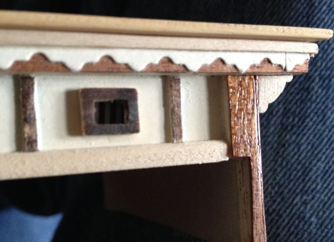
George, It has been about eight years ago since I built this part of my Flying Fish, but if memory serves me correctly, I used 24ga brass wire for my vent pipes and they don't look too far out of scale. What I do remember is how much of a pain they were to install since I didn't put them in until after I built the toprail. At least I put them in before the pinrails. Here are a couple of old pictures from the build that may help. -Brian

- 602 replies
-
- 2
-
-
- Flying Fish
- Model Shipways
- (and 2 more)
-
Wefalck, I have been studying up on how to do this, and there are numerous helpful videos on YouTube with all sorts of methods. I see where a lot of people use weathering powders while others save (lots of) money and pulverize pastels to achieve the same effect. The one thing that surprised me most was that several of the videos suggest that you use ordinary hair spray to "fix" the weathering to your model. It has the same affect as varnish but it doesn't change the appearance of the coloring as much as varnish does. I just purchased a cheap set of pastels and will give that a try first. Fingers crossed that it works out. -Brian
-
Thank you Eric. I reused my mockup for rigging my cannons as a test bed for weathering using pastels. I added planking and armor to it and just got it painted this past weekend. I will wait on the clearcoat to cure for a few days before testing it out. I am anxious to see if I can add a little "age" to my build, and tone down the "pristine" look a bit. We'll see how it goes. More to come.... -Brian
-
Wefalck, There is an art to firing the big guns, especially at moving targets. These gunners were definitely quite good at their jobs, and I'm sure there were many hours of practice under their belts to get that good. Although it is not American Civil War related, but a good example of an experienced mortarman is Master Gunnery Sergeant Leland Diamond, he has a pretty interesting history over his career. Part of his story is during WWII he single handedly drove off a Japanese cruiser at Guadalcanal with his mortar. -Brian
-
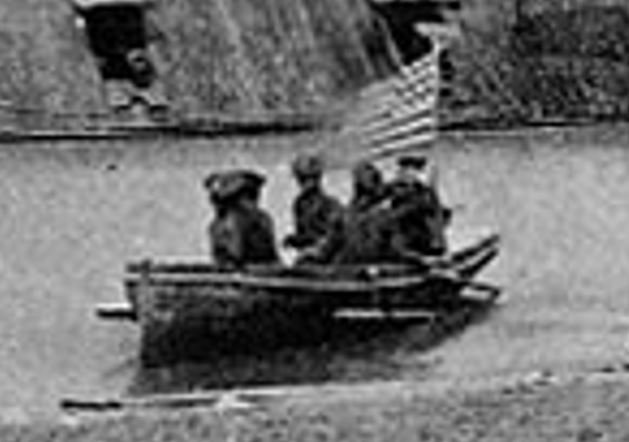
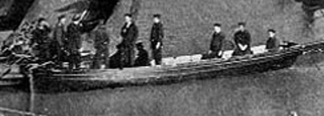
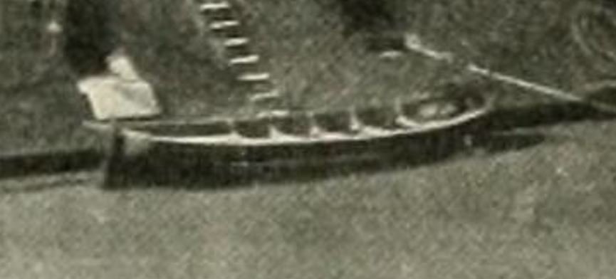
Roger, thank you for the kind words and info. I guess I need to apologize for using the term "lifeboat", I seem to recall a similar conversation with you about the workboats on my Chaperon build. It's a bad habit I need to break. 🥴 From some of the pictures that I have studied, the ships boats all looked pretty similar. Flat transom, roughly 25' in length with about 6 or seven benches. Nothing too fancy. If there is a difference in them, it is minimal, or at least difficult to tell from zooming in on the old photos. This one if from the Pittsburgh. Cairo Cincinnati. I did go back and do a little re-reading on the sinking of Cairo however, and found that I had misspoke about her boats not being launched. Here is an excerpt from “Hardluck Ironclad: The Sinking and Salvage of the Cairo” by Edwin C. Bearss. So it does seem that the crew was able to get at least three boats launched before she sunk, but as to what became of them afterwards, there is no telling. Most likely became the property of other boats in the flotilla. I will also give Chapelle’s American Sailing Navy a look before outfitting my boats to make sure that I get them right. Thanks again! -Brian
-
Thank you so much George. While I definitely agree that an armored cover may have been way to heavy to move on and off, my thoughts were that the cover was simply made of wood to keep out the elements. Of course like you said, one made of wood would not provide much protection from enemy fire. Then again, there wasn't any protection from plunging fire at all on these boats. Most of the armor plating was to protect the pilots, frontal assaults and the machinery within. There were even accounts of snipers shooting the tiller ropes to disable the boats mid stream. With no control, they made for easy targets for the enemy. As for displaying at Vicksburg, that would be awesome. Not sure they would take mine though since they already have a 1:48 scale model there. But it would be a treat to show it off. -Brian
-
Thank you Mark for the kind words. As for the armor plating on top, there was none. These boats were pretty much unprotected from plunging fire, at least during Cairo's time. There may have been modification later on, but I have not researched that since my focus has been on Cairo. I was mostly referring to the additional course of timbers that were installed on the forward, vertical sections of the pilot house. The original plating was reused when the extra timbers were added and four additional plates were added in the gaps left exposed by the expansion of the new timbers. Flag Officer Foote was injured when the pilot house armor plating of the St. Louis took a direct hit from a Confederate cannon ball from Fort Donelson. The impact shattered the iron plates and sent shrapnel into his ankle. Same thing for the crew on the Louisville, shrapnel killed the pilot and other men that happened to be in the pilot house at the time. Lt. Bryant was determined not to have the same thing happen to Cairo so he had the modifications done a few weeks after the battle. Several other City Class boats followed suit shortly after. Fort Donelson is on my list of places to see, along with Fort Defiance. Even though nothing remains of the old shipyards, it would be neat to see the place were they came from. -Brian
-
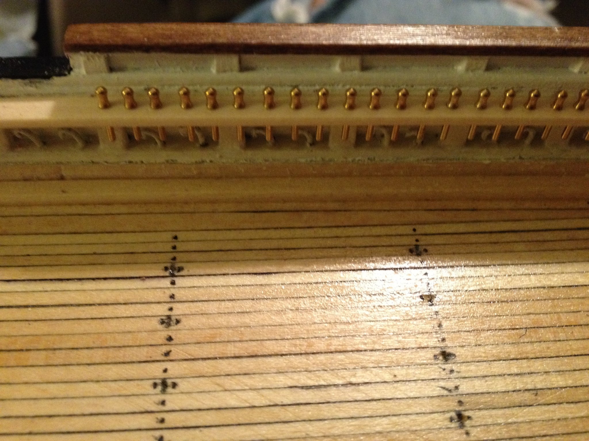
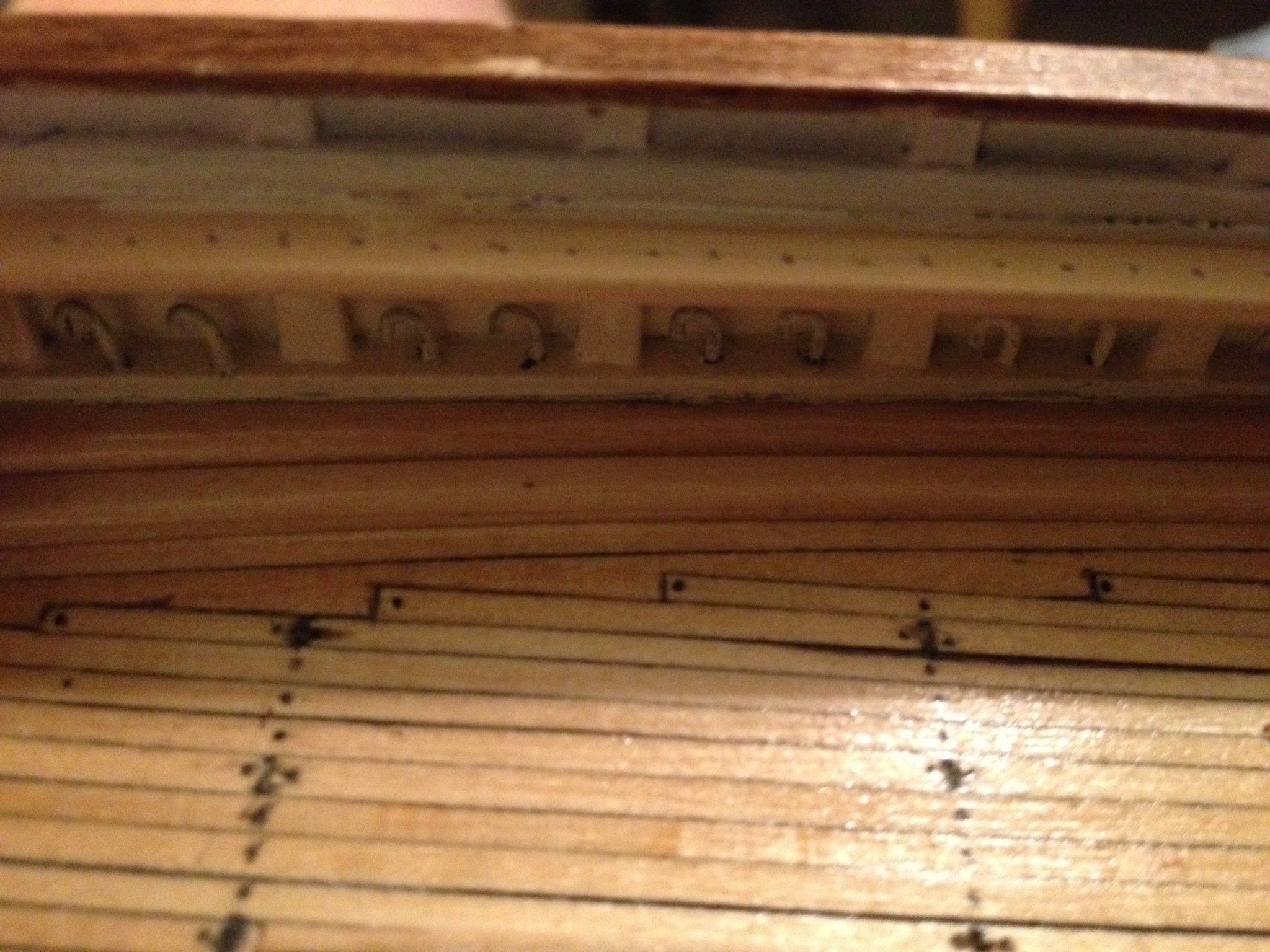
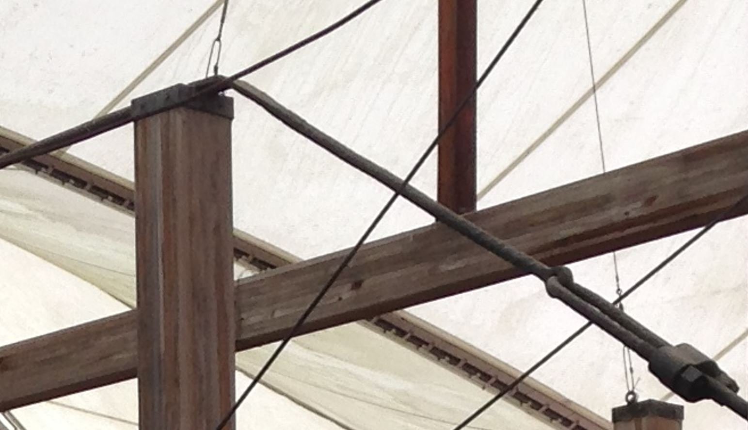
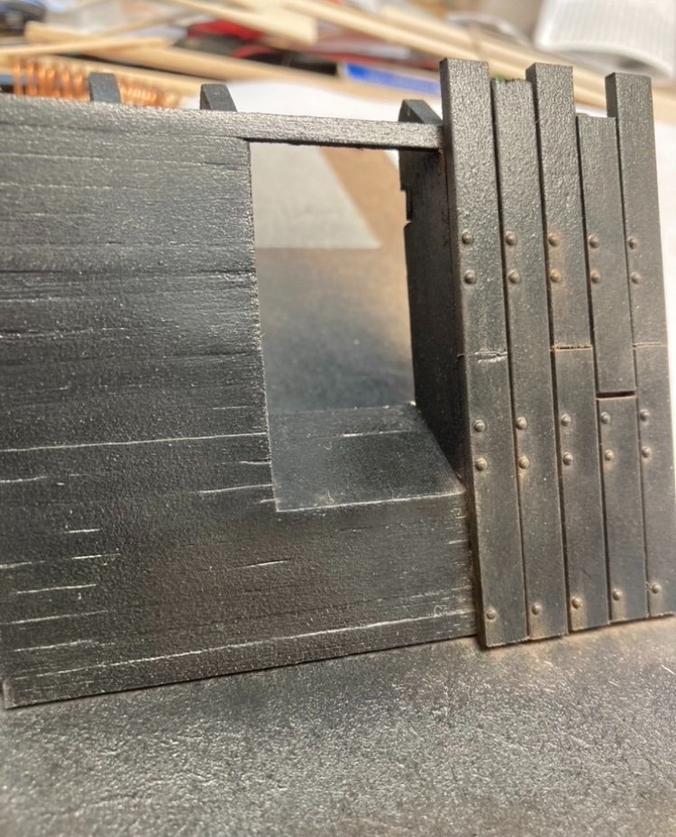
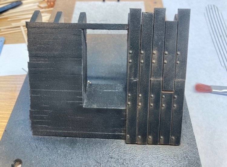
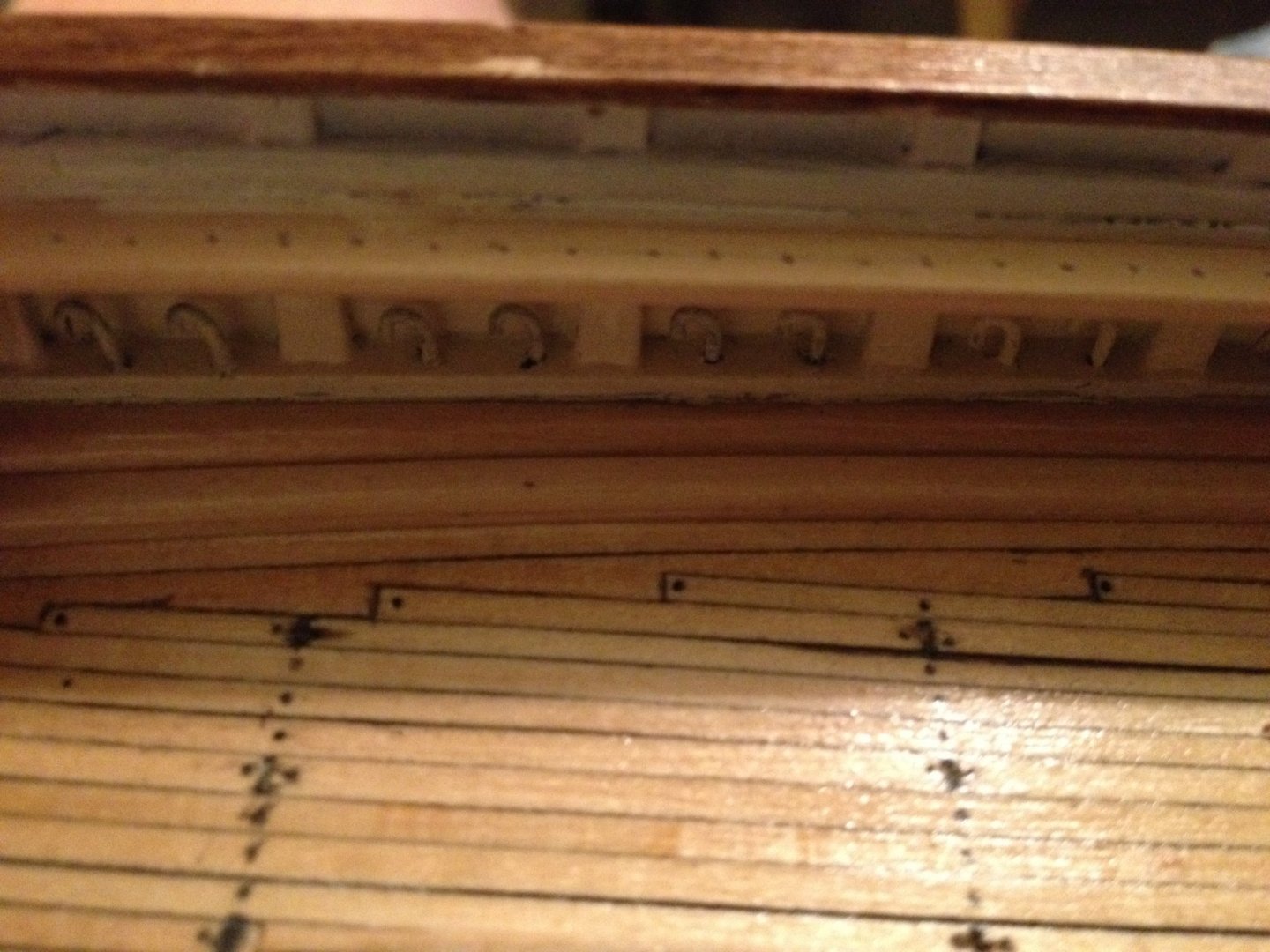
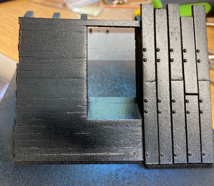
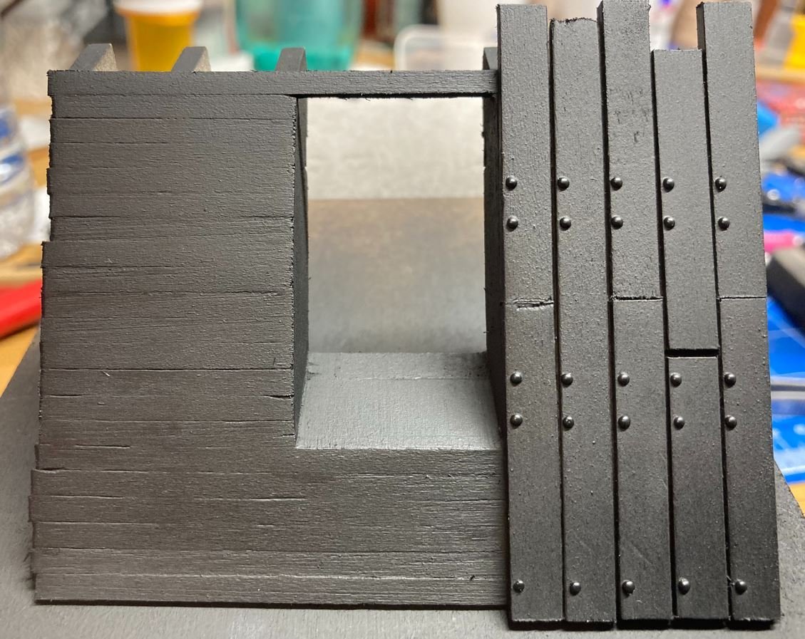
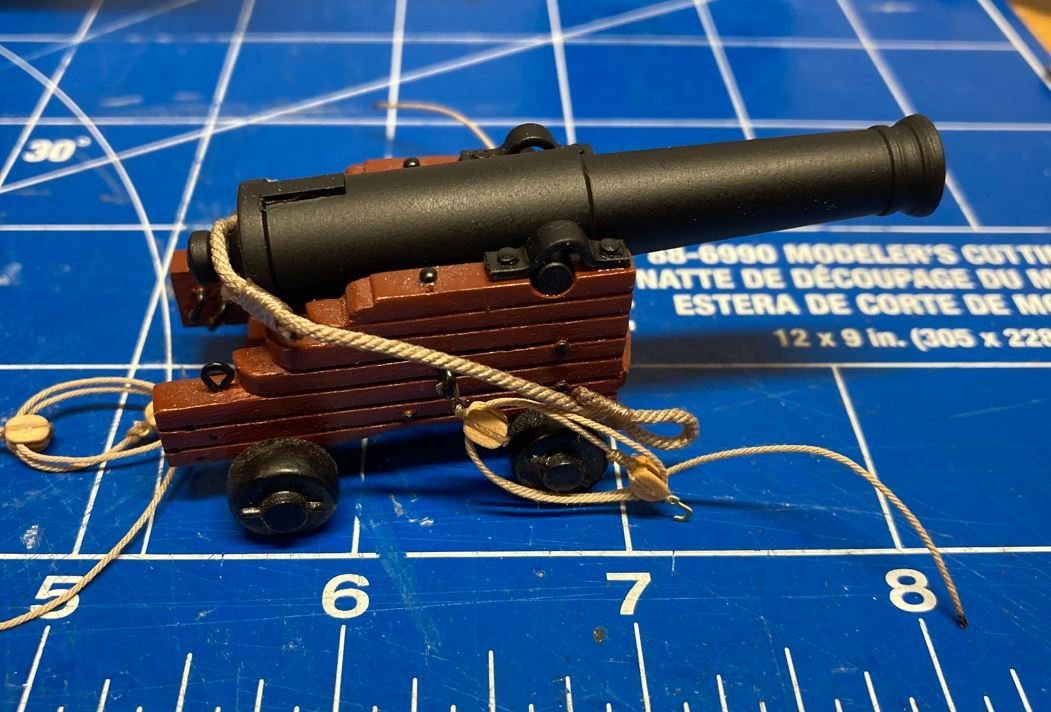
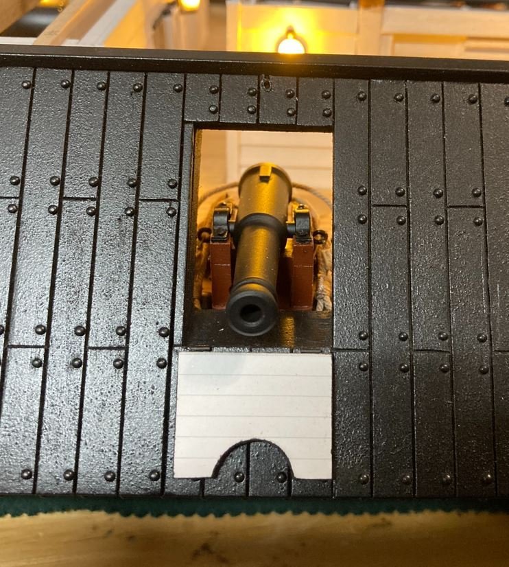
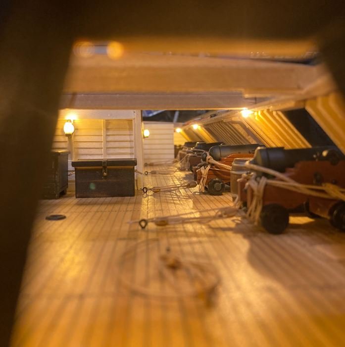
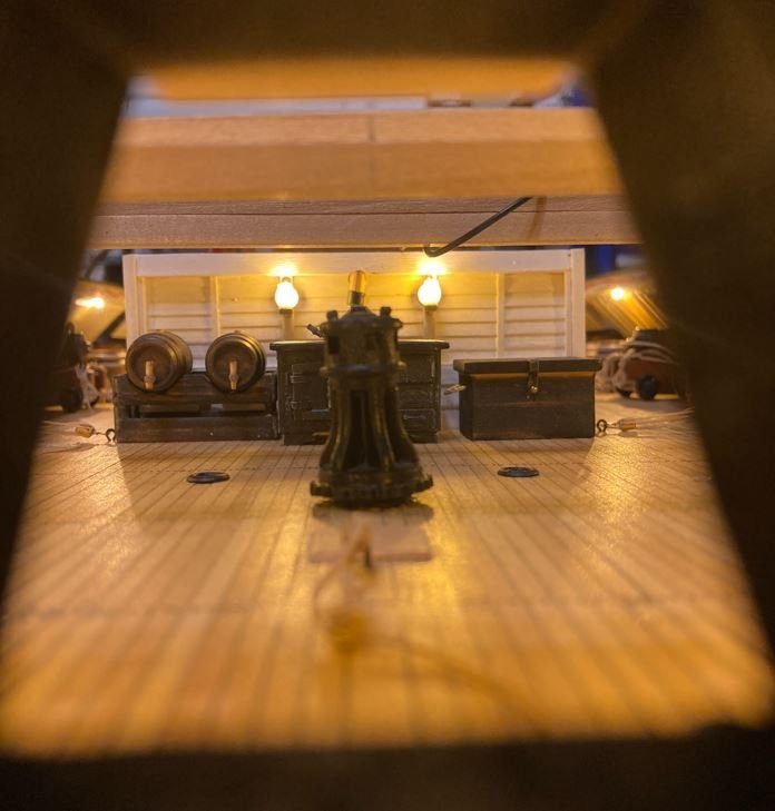
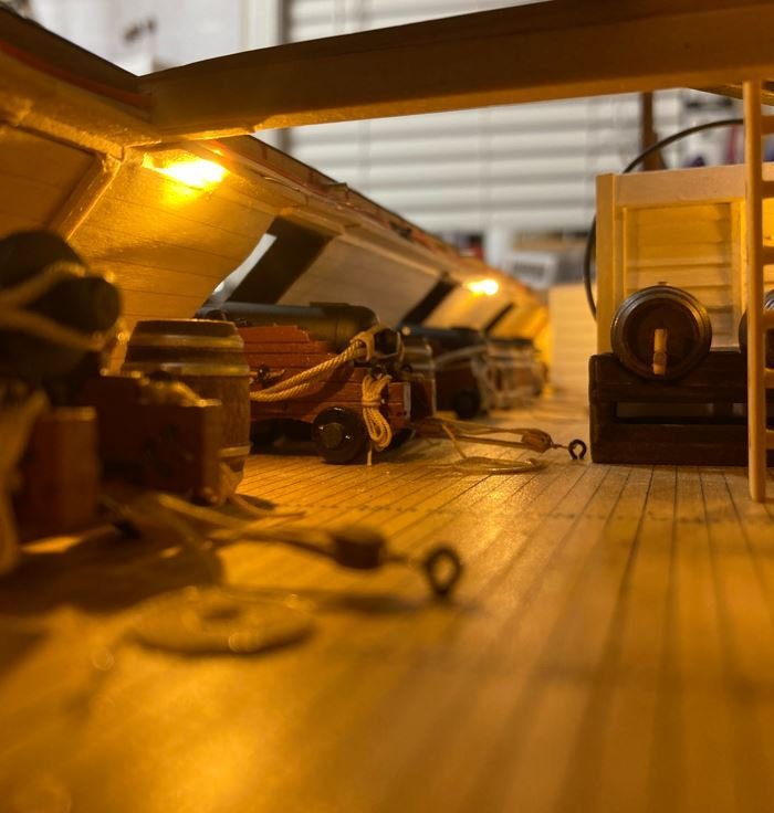
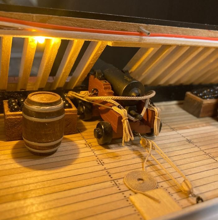
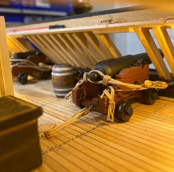
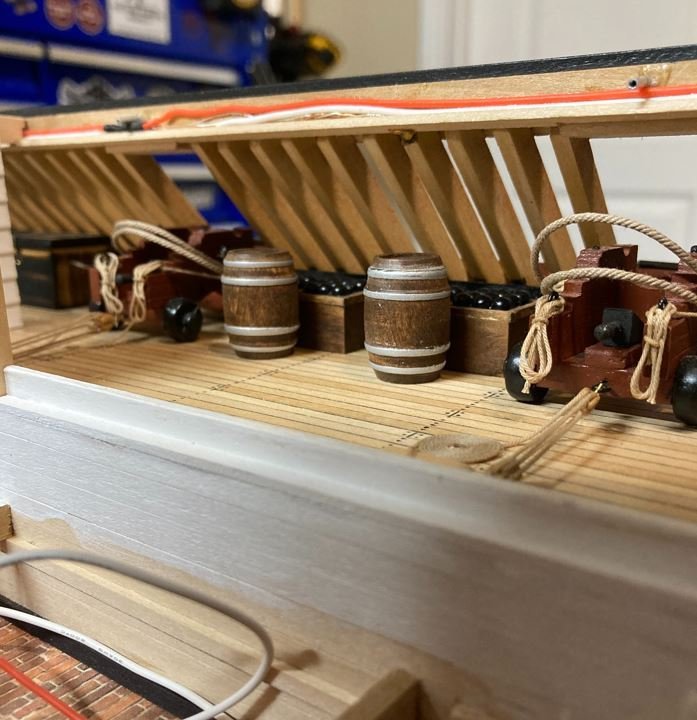
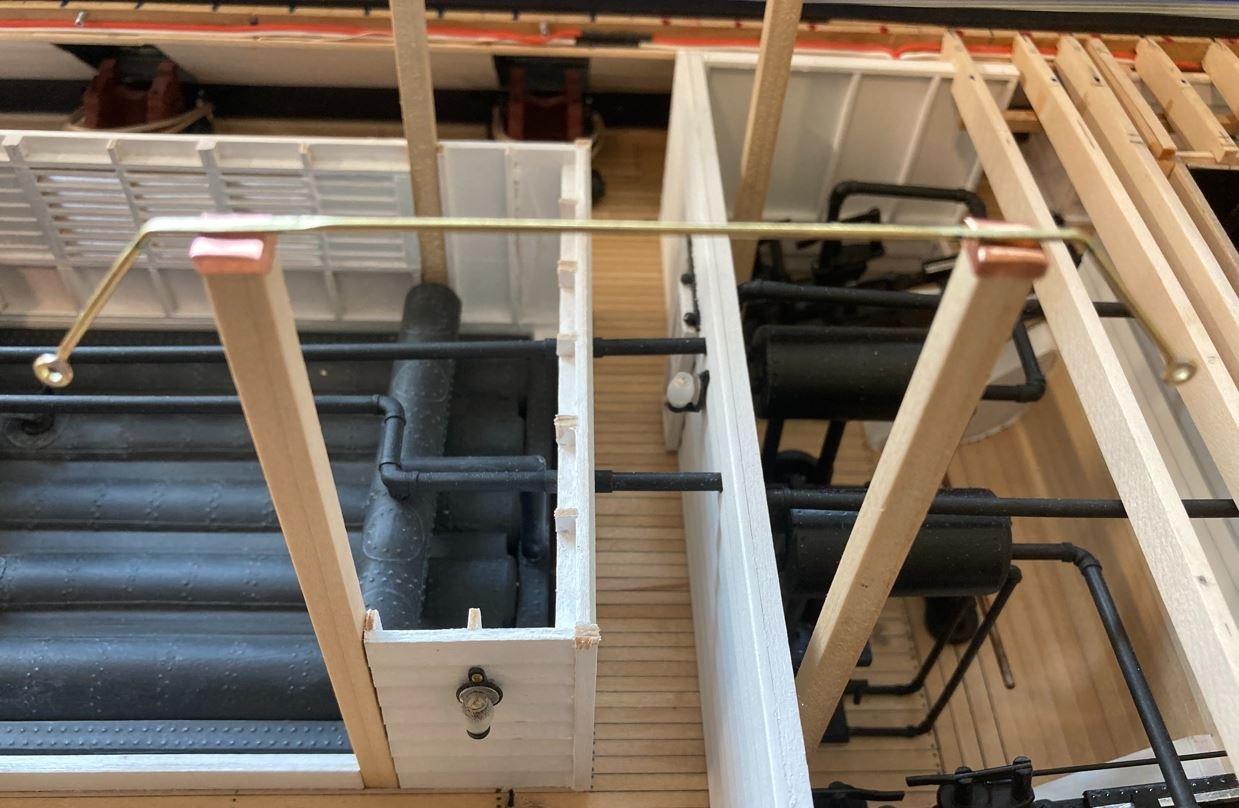
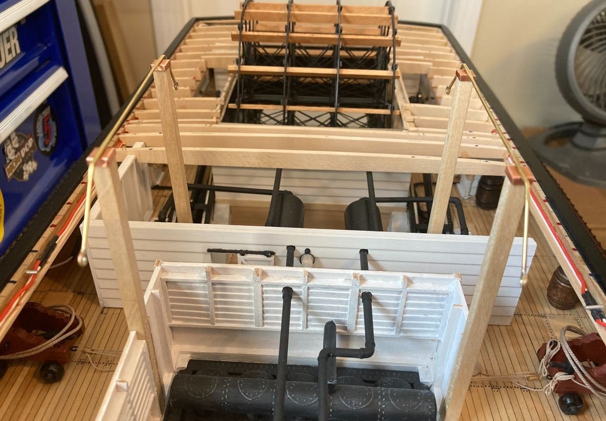
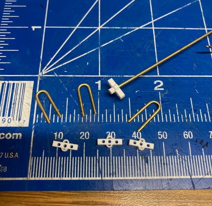
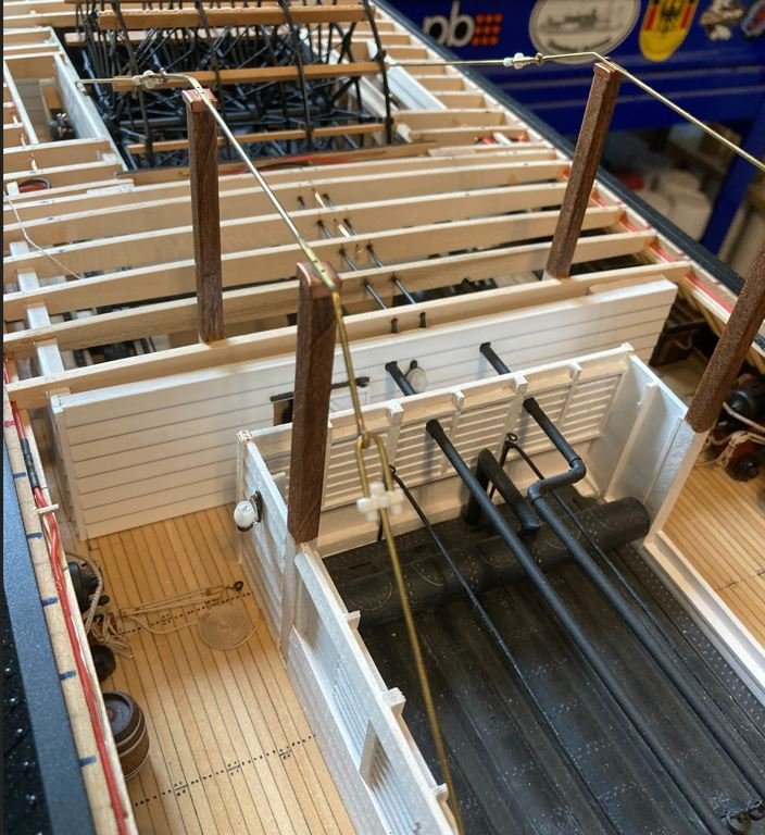
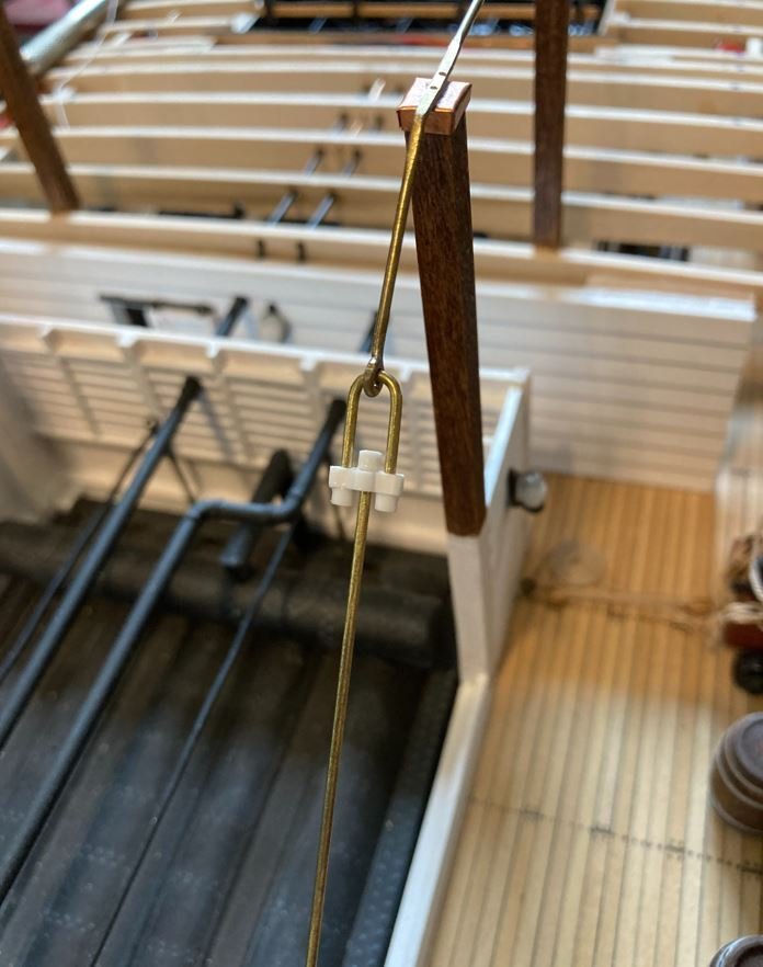
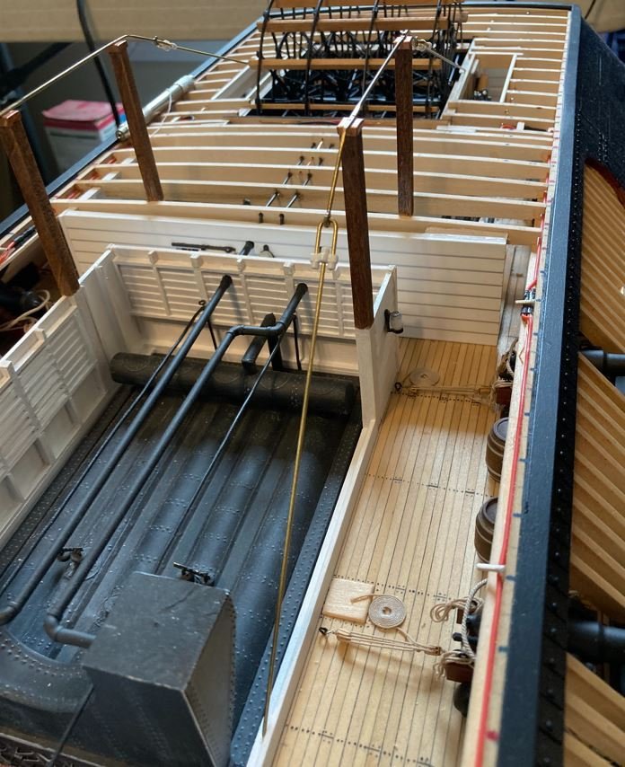
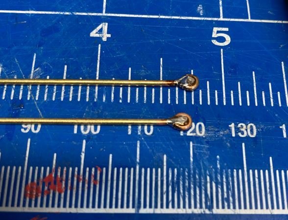
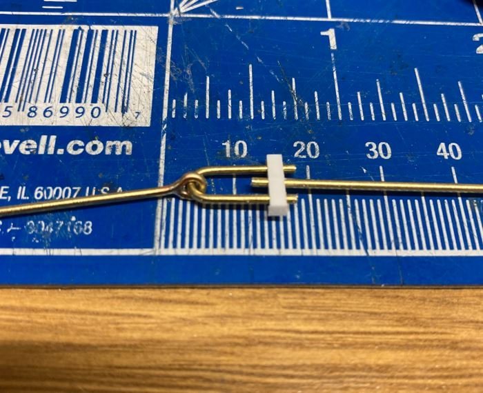
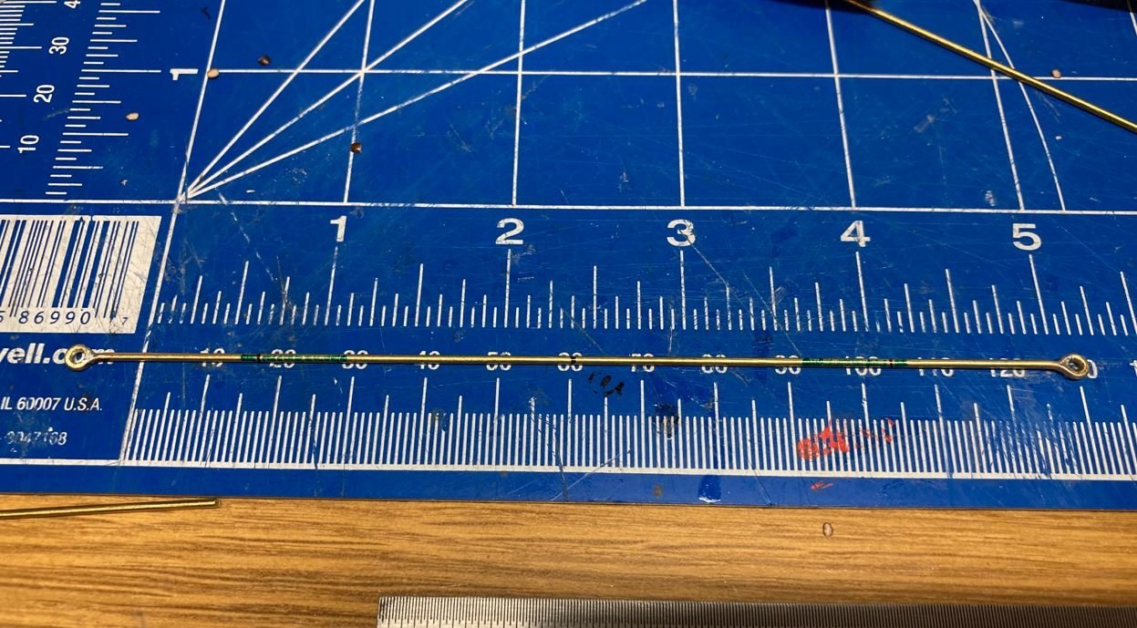
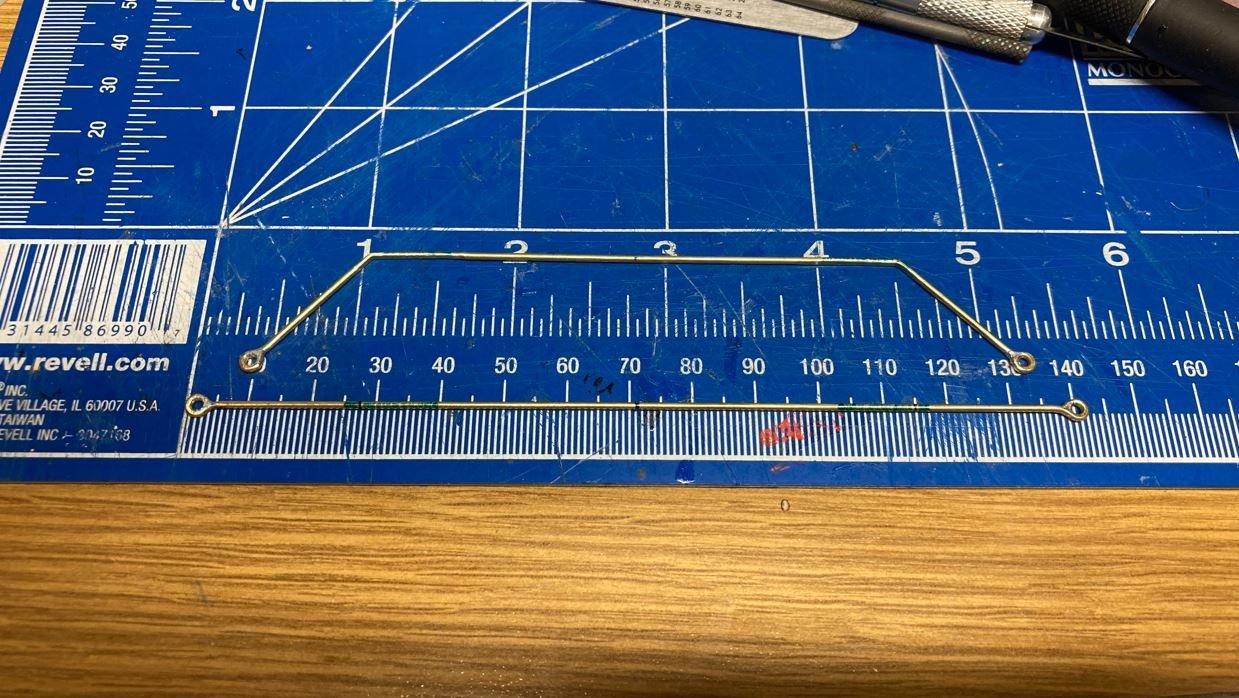
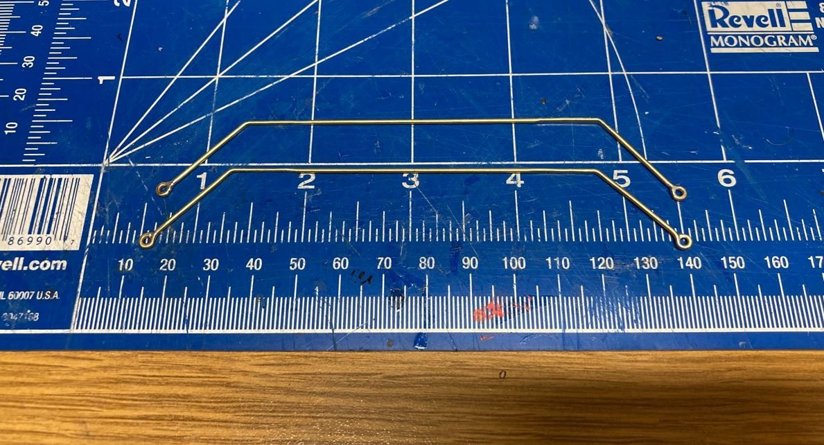
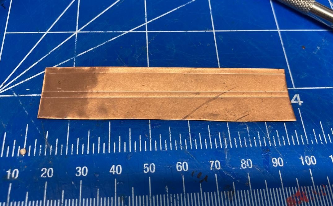
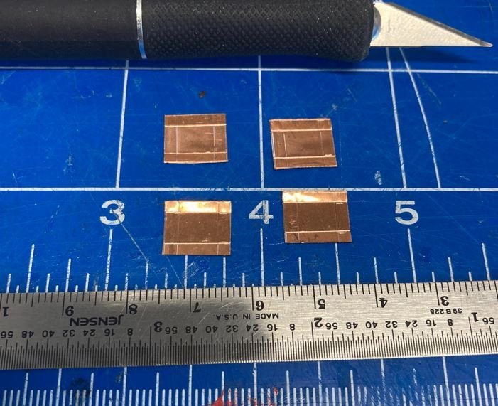
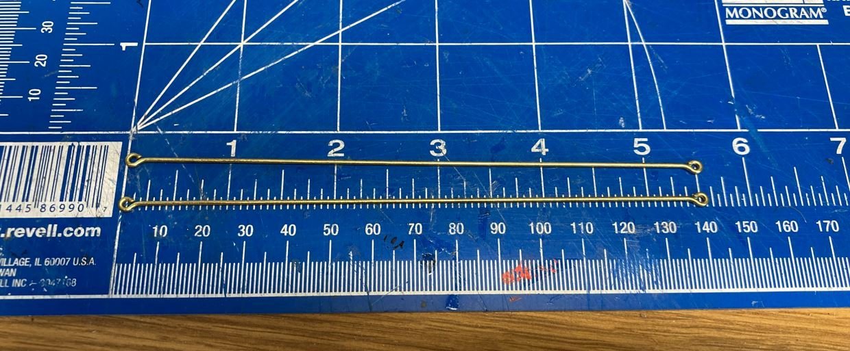
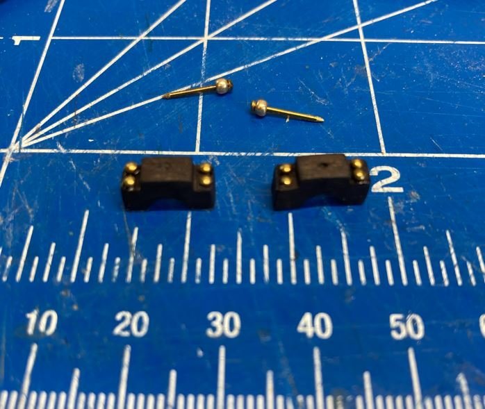
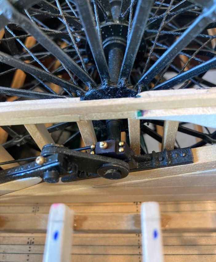
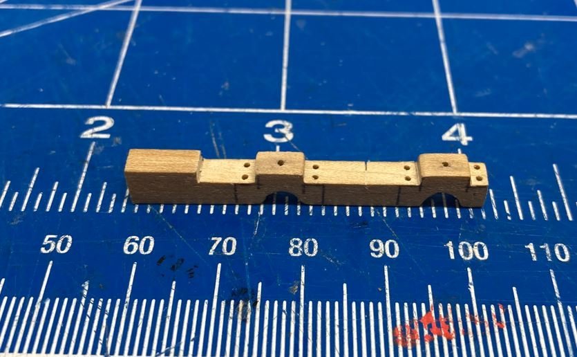
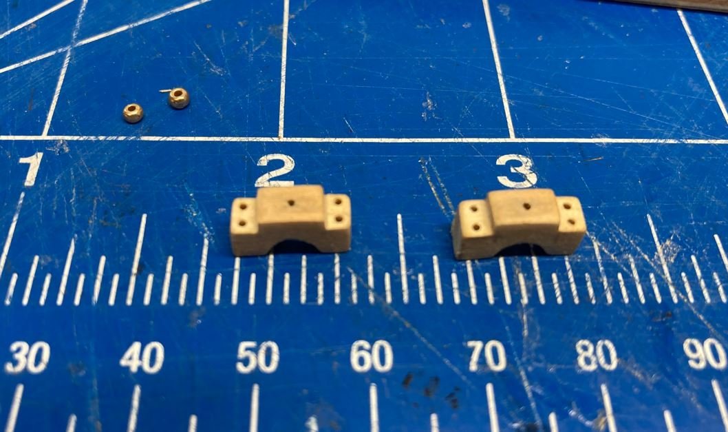
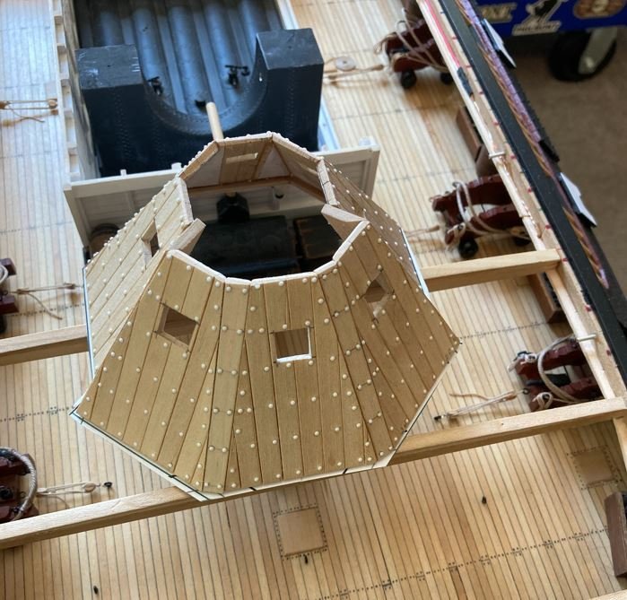
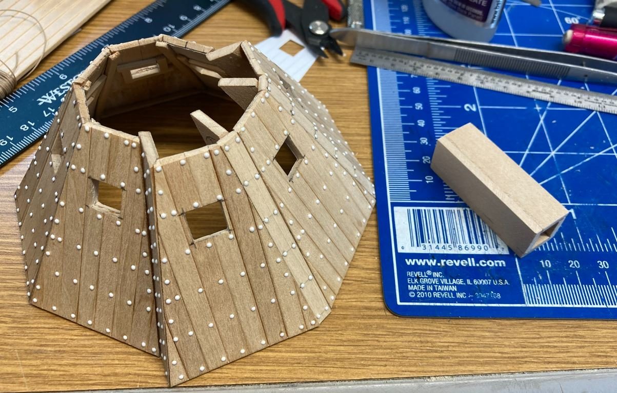
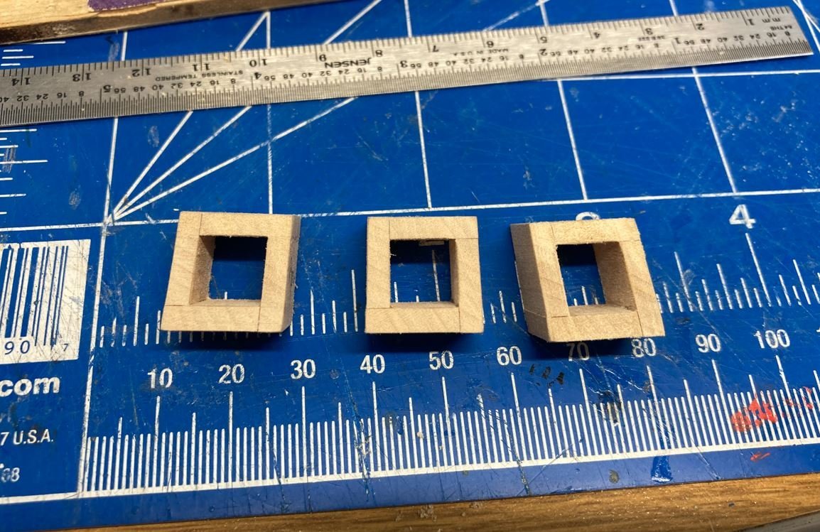
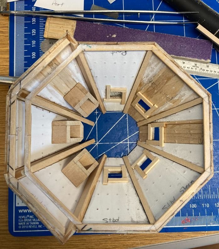
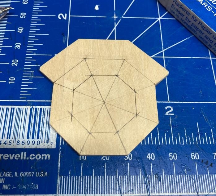
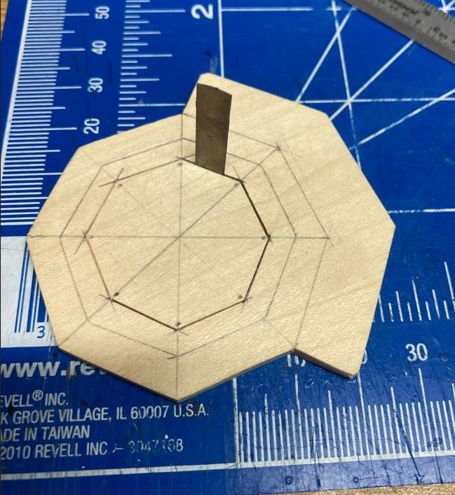
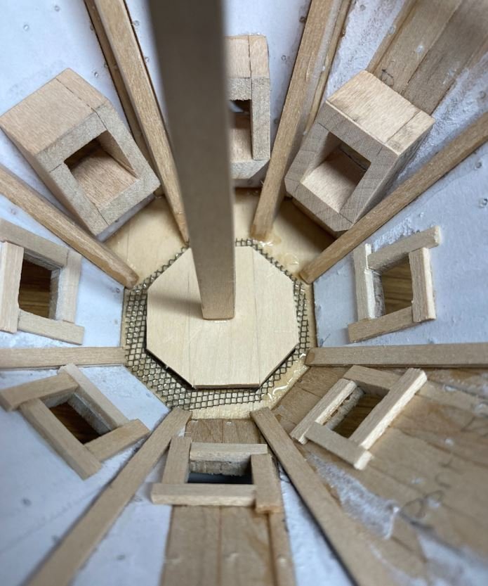
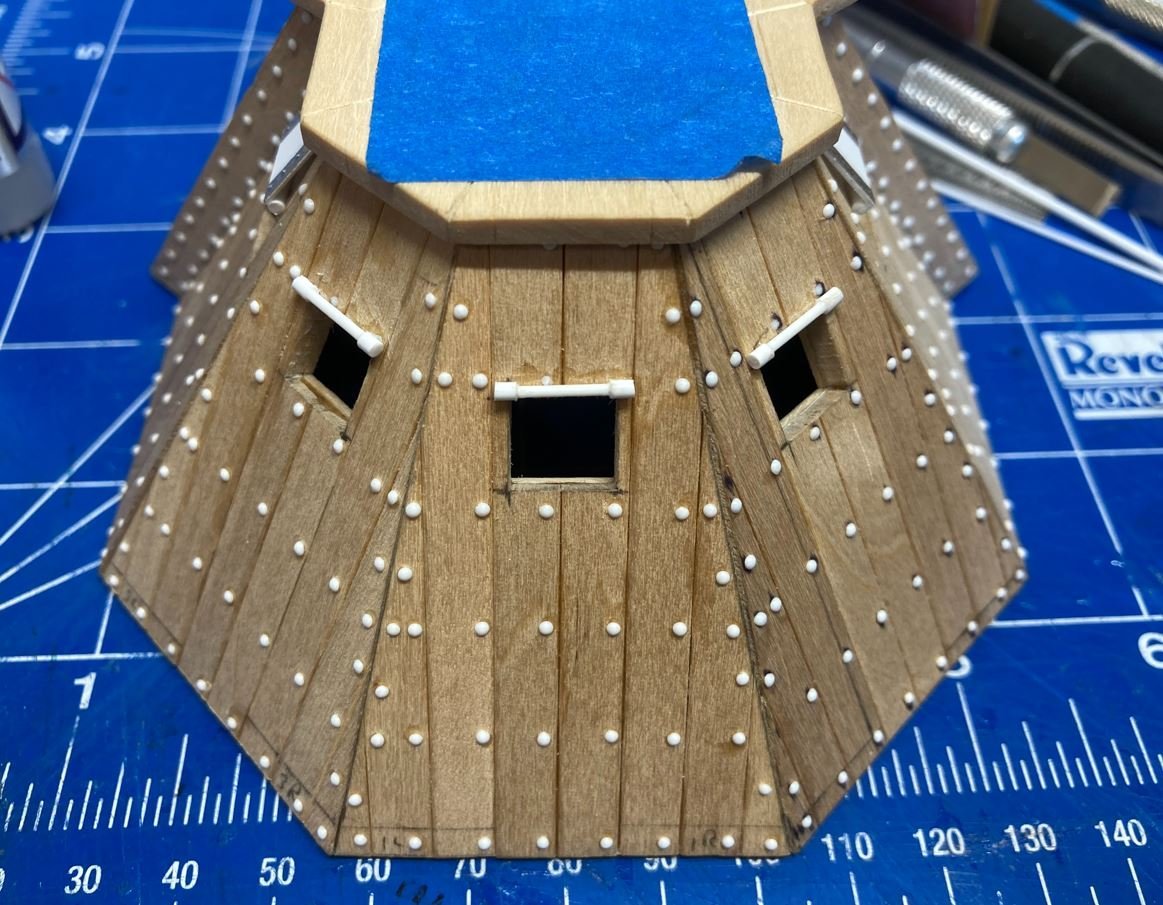
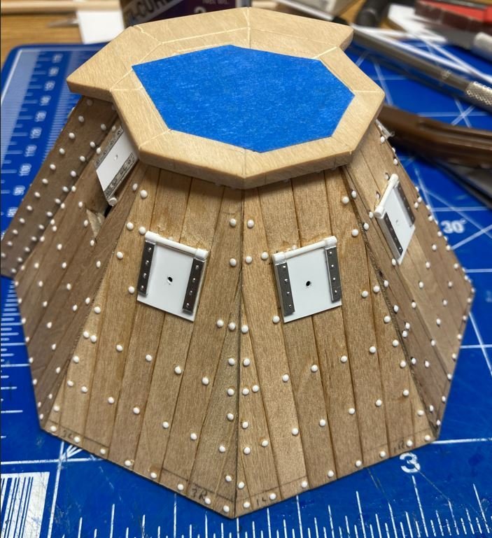
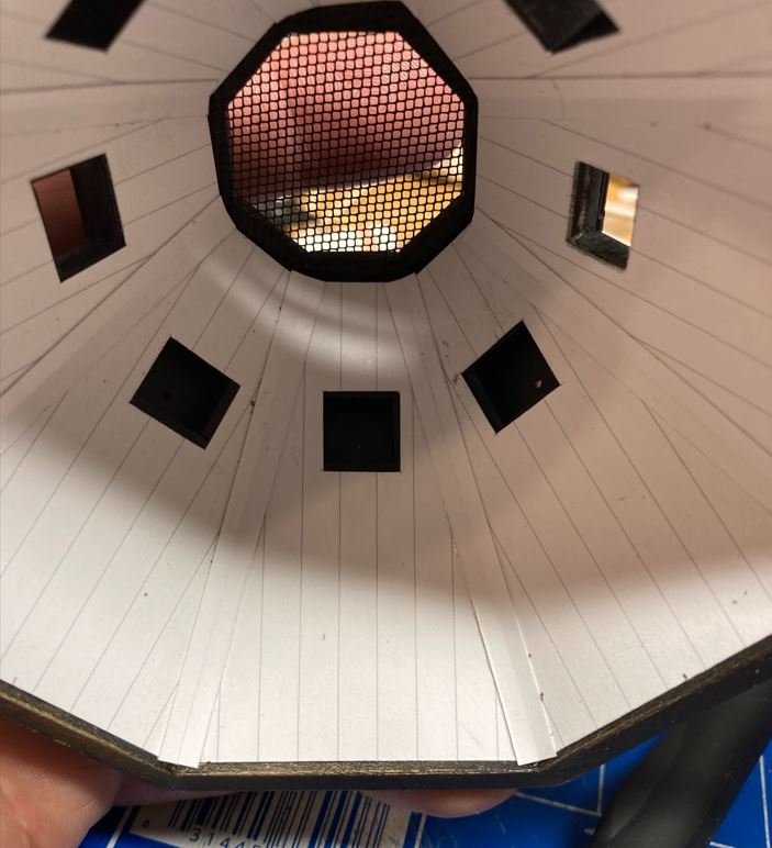
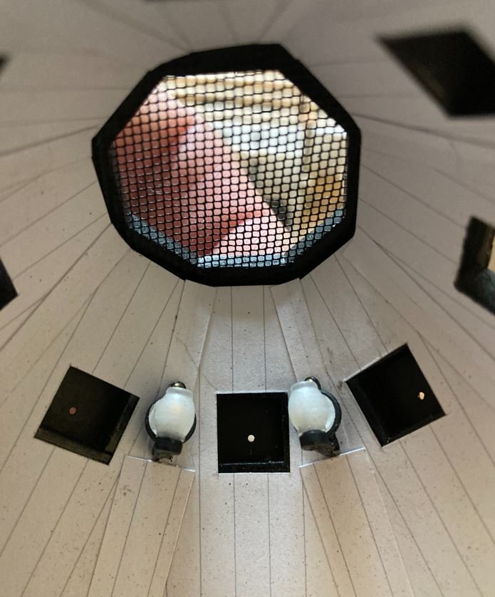
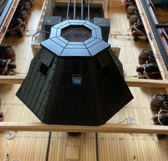
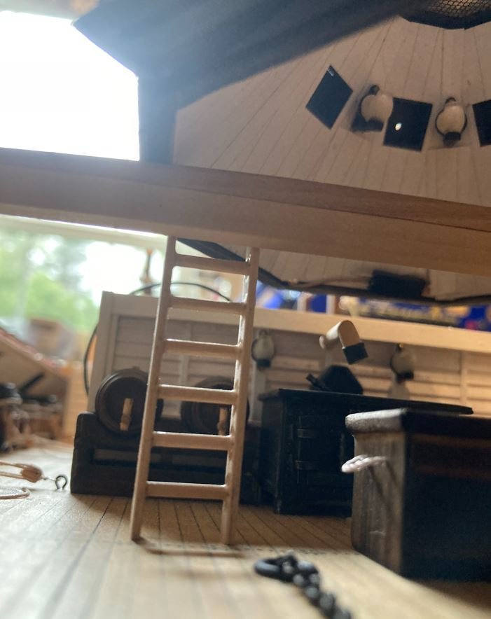
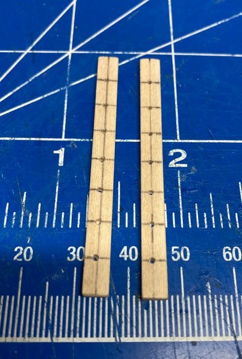
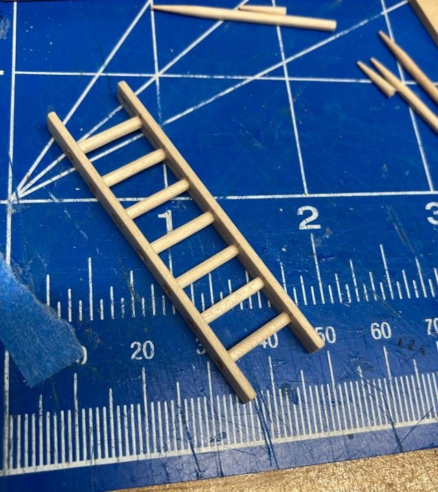
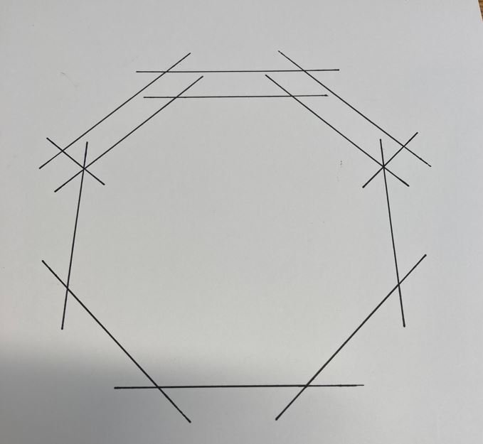
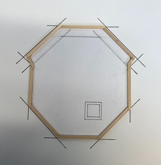
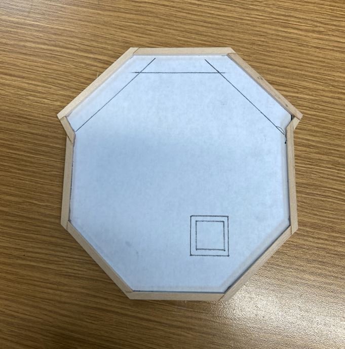
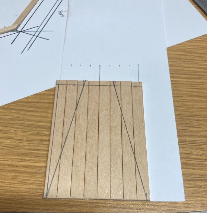
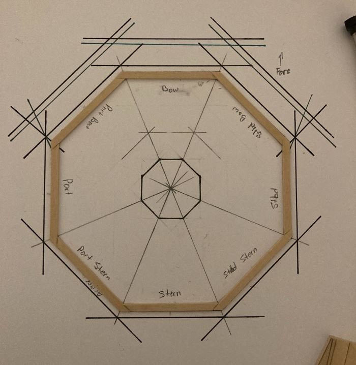
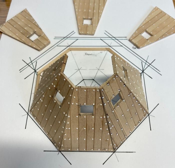
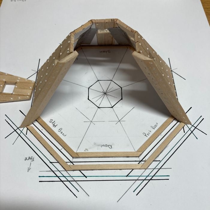
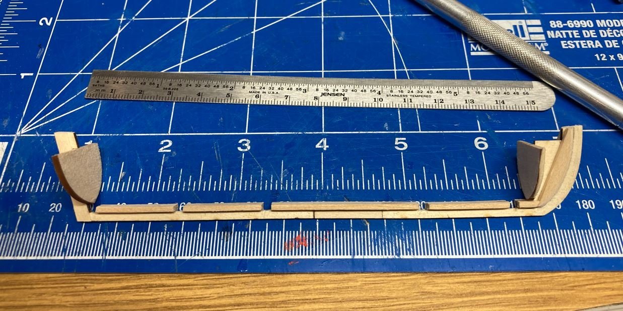
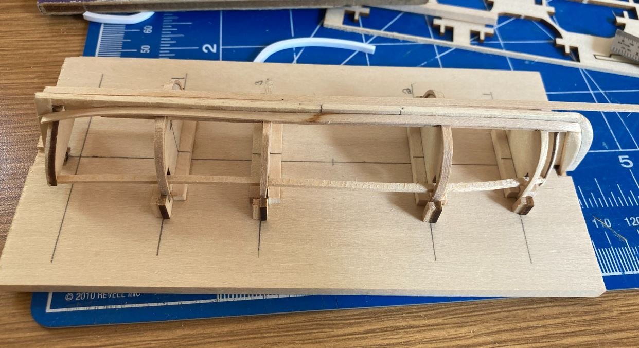
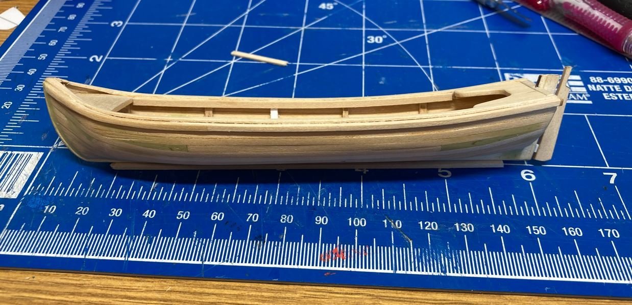
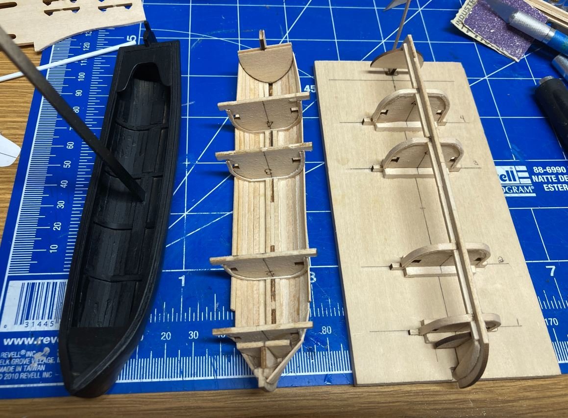
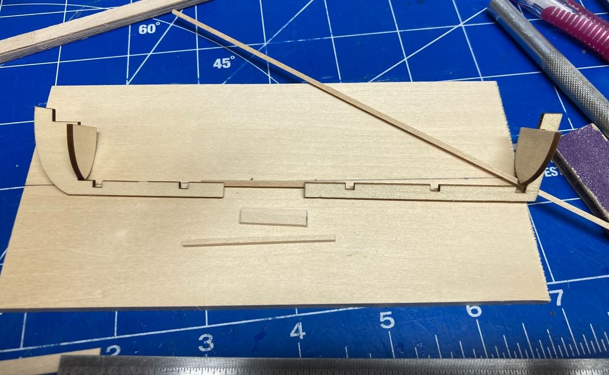
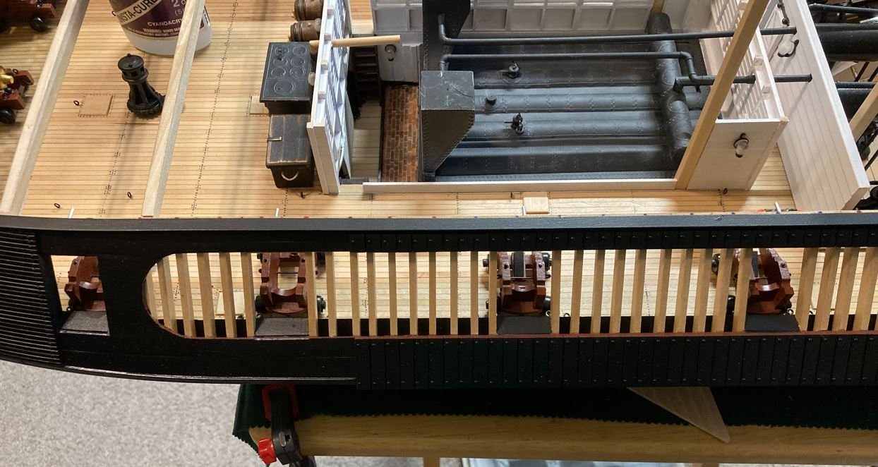
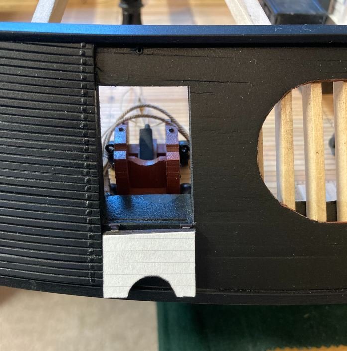
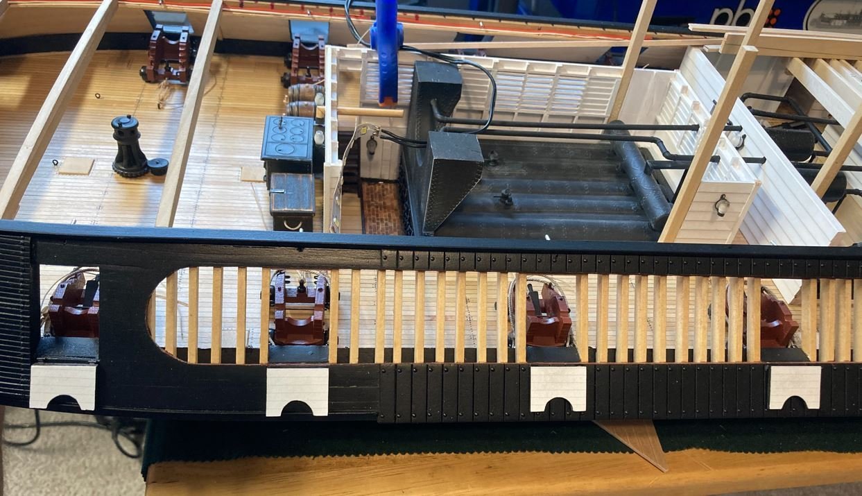
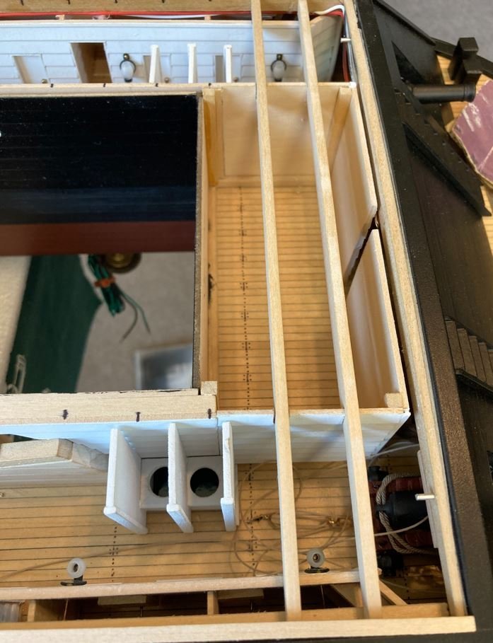
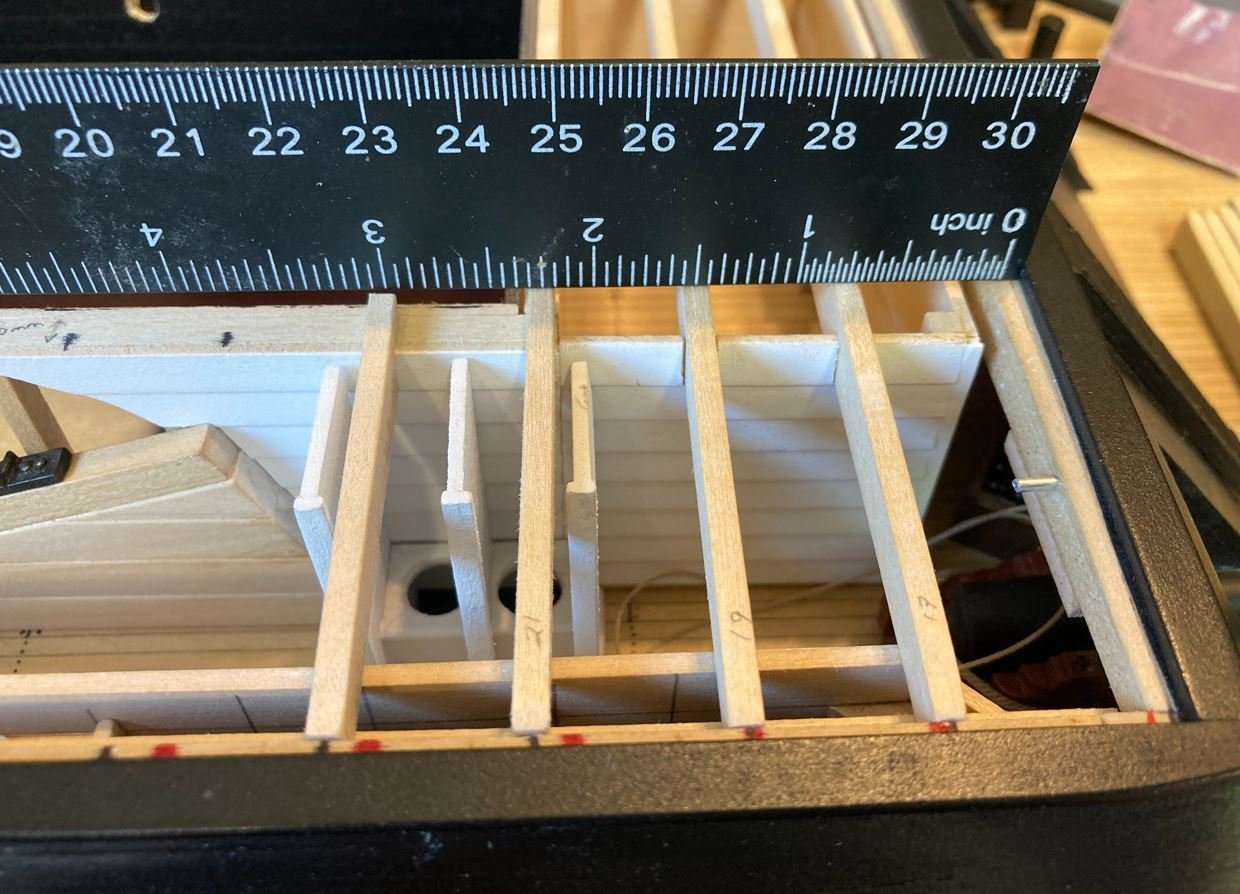
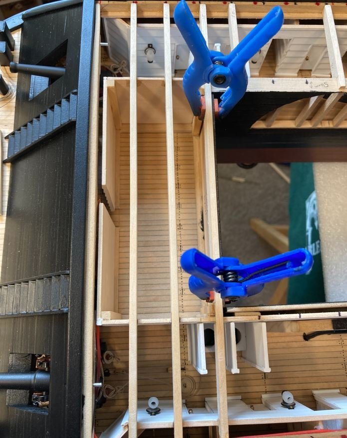
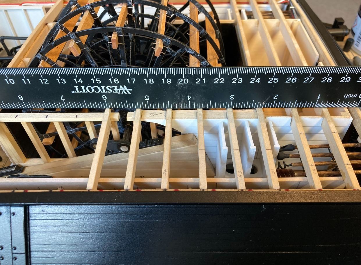
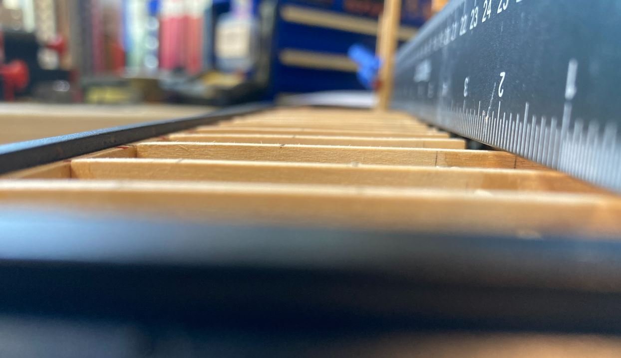
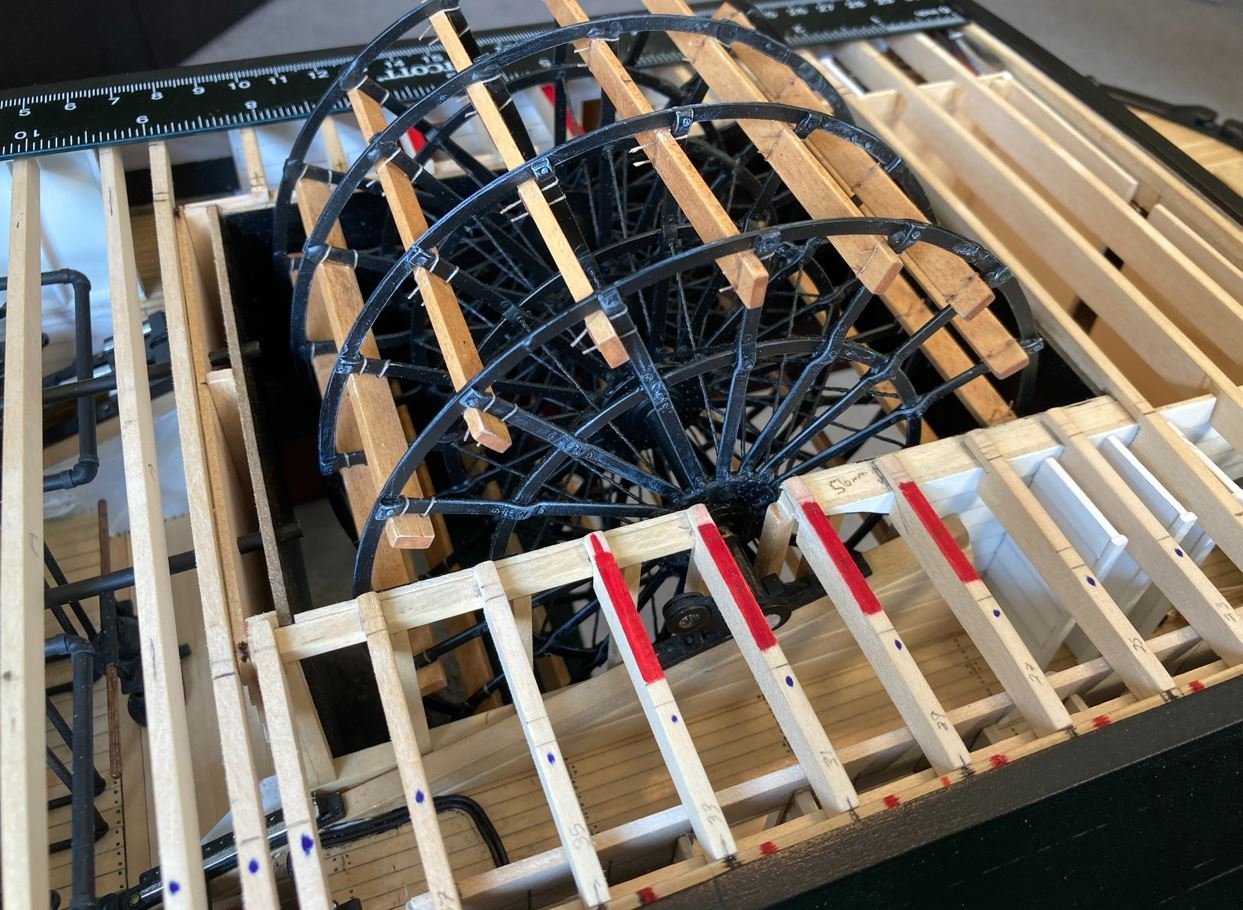
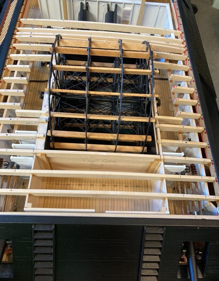
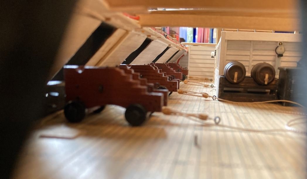
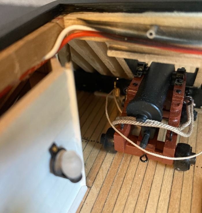
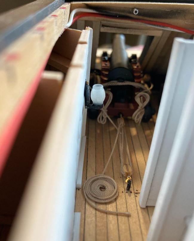
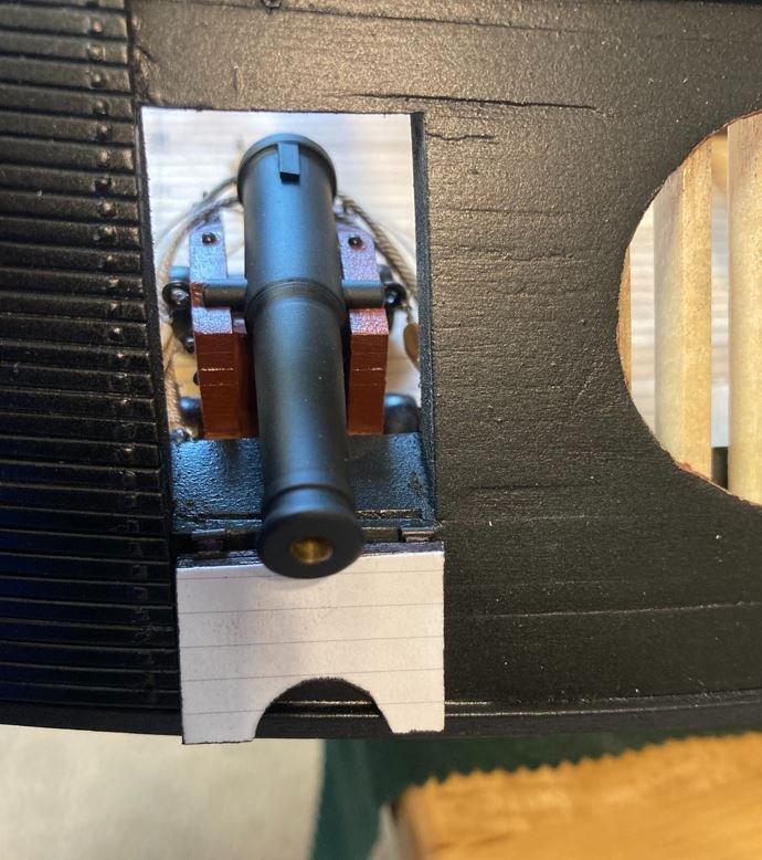
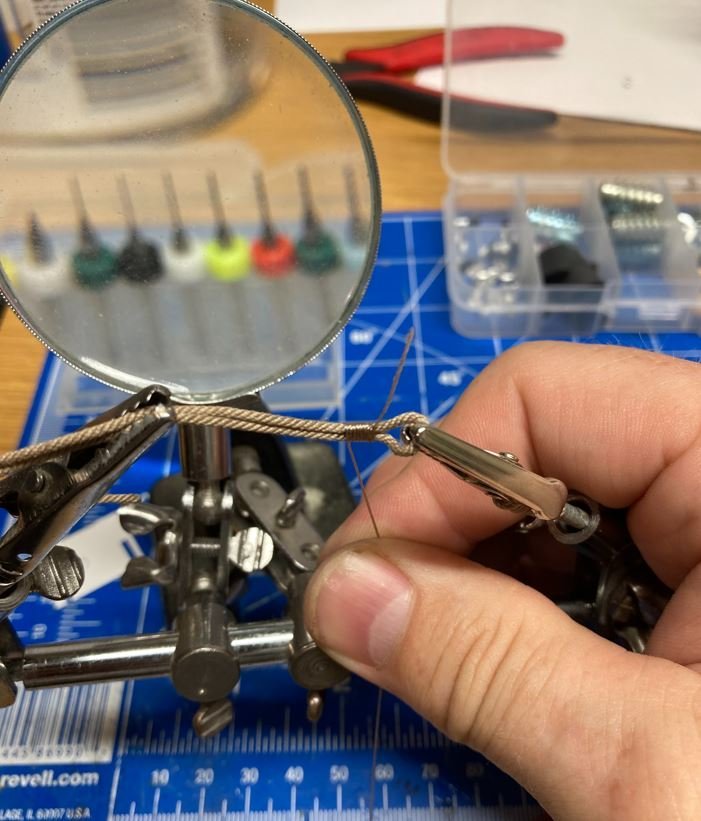
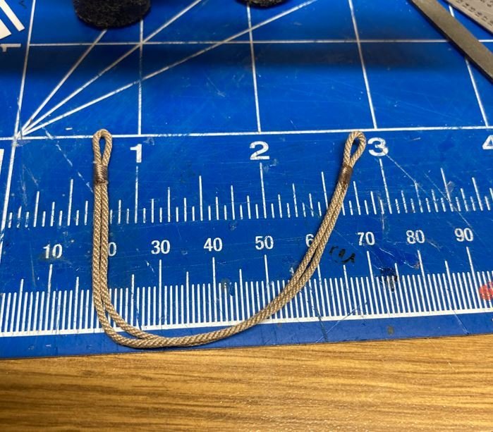
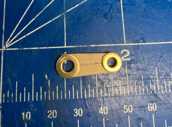
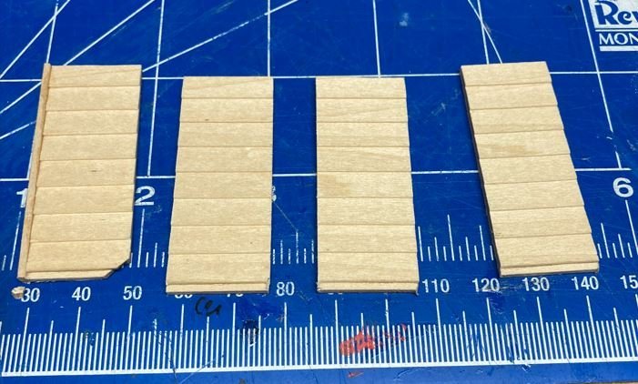
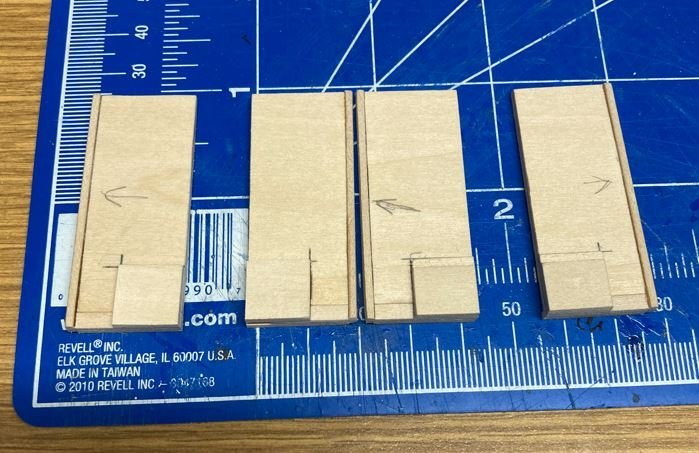
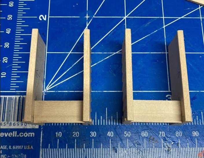
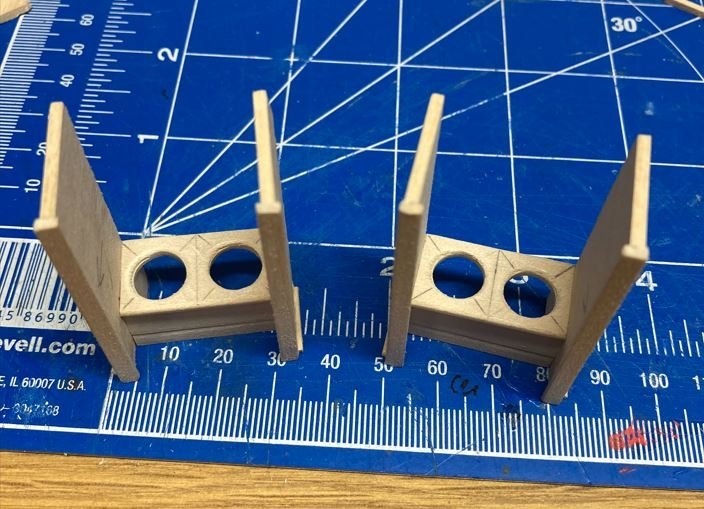
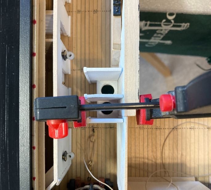
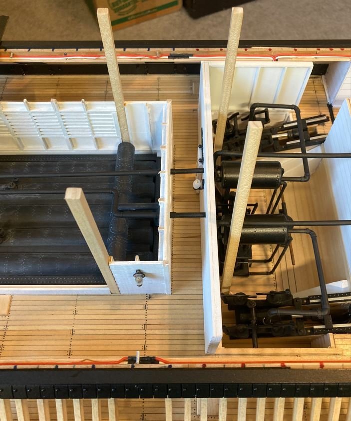
Hello again everyone, Time again for another update. With the summer winding down and the weather cooling off, I have been busy with my "Honey Do" list but managed to find some time to put together a few more items on my build. I finally finished getting all of the remaining cannons installed and rigged. The three forward cannons are complete with the exception of the rope coils. I managed to run out of rope with only a couple of feet needed to finish, but more is on the way. Picture of one of the forward 42 pounders rigged and ready for install. One of the starboard side 8" Smoothbores in place. Here are a few pictures of the gundeck at eye-level showing powder barrels, munitions crates and the crews mess lockers. Next I worked on the hog chains. For these I used brass wire for the chains themselves, styrene for the turnbuckles and copper sheeting for the cast caps. Up close picture of the actual hog chains. These took a little bit to figure out exactly how they were built. I had a few personal pictures from my last visit in 2014, but none with any real detail. I did try looking up some others on the internet, but the hog chains don't really seem to be an area of focus for visitors so the pictures are limited to long distance shots that I had to zoom way in on. Nevertheless, I think my interpretation of them is fairly close. Here is the horizontal chain with the ends formed into the eyes. Then it was time to test my metal working skills to see if I could solder the eyes to close them up without making a mess of things. Well, almost. Nothing a little drilling and filing can't fix. There we go. They look a little better cleaned up. Now to get them bent into shape. The forward chains are significantly shorter than the aft ones, due to their placement, so the angle on them was a bit more. Also, where the hog chains rest on the posts the iron was pounded flat to give it a better mounting surface. The green area drawn on the wire is where I flattened the brass to rest on the caps. Both horizontal chains shaped and flattened. Next came the cast caps. These were made from thin copper sheeting that I cut to size and scored along the folding edges to get the correct shape. Then they were placed on the hog chain posts and glued to the horizontal chains. From the pictures that I was able to find and zoom in on, it is difficult to tell if there were bolts that were inserted through the chains and cast caps into the tops of the posts. It would make sense for them to put something there to avoid the chains from slipping off, but since I was not able to find any pictures of the tops of the posts, I took my builders liberties and drilled them out and will place bolts in them. Next work was done on the turnbuckles. Or at least that is what I think these are called. They are not built like regular turnbuckles but they look to function as a way to tighten the tension on the hog chains. These were built with the same brass wire and styrene plastic. Partially assembled. and temporarily installed. Port side. Starboard side. Before I got too far ahead of myself, I remembered that I had not built the axle pillow block caps. So I figured that I had better get to these before they were buried and impossible to install. These I just carved out of a piece of square stock and sanded to shape. Cut out and just needing a little finish sanding. Sanded and painted. I use the gold beads to simulate the grease cups. With the small nail in the top, I think they look pretty convincing. And all mounted in place. Next came work on the pilot house. I was not actually ready for this part, but I was running some additional lights before I closed up the boiler for good (I ran all of my wiring to terminate under the boiler) and had the thought that it would be neat to put some LED's in the pilot house to give it a little additional detail. So, I decided to go ahead and get it built. So to give a brief history on the pilot house. The original plans for these was a wooden octagonal substructure, 12" thick with 1.5" thick iron plates fastened to the frames for protection. After several men on the Louisville and St. Louis were injured or killed by flying shards of iron from direct hits on the pilot house during Battle of Fort Donelson, including Flag Officer Foote, Lieutenant Bryant (then commander of the Cairo) had some modifications done to the pilot house in order protect the crew from further injury. While Cairo was awaiting her next assignment, Lt. Bryant put her crew to work extending the front three panels of the pilot house. They added an additional 7.5" of timber to each panel and then reinforced the inside of the house with pine paneling. Additionally, 1/2" thick iron flaps were added to the ports as well to protect the pilots form enemy sniper fire. When these ports were closed, the pilots would have to navigate by squinting through a peephole drilled into the flaps that was about the diameter of a silver dollar. All in all, these modifications gave the pilot house its new unique shape. So I started out by tracing the footprint of the pilot house from the HSR plans. I drew the footprint up on some card stock to use as a mounting and construction base. I over extended the lines to give me a cutting line for the toe boards, then glued the strips down for the toe boards. Once the boards were all in place I removed the excess card stock to start going vertical. Once I had this part cut out I realized that my octagon shape was not uniform and that the sides of the pilot house extension weren't even. So I went to the computer and dug out my trusty Visio program to get a perfect Octagon shape. Then with careful measurement, I added the extension to the octagon then sized everything to scale. This is the new result. Much more uniform. First course of toe boards in place. Then it was on to building the sides. Five sides up and rivets installed. I simulated the rivets the same way that I did for the casemate armor. Extension sided in place. These were added when the front three panels were beefed up to compensate for the new thickness. All eight (actually ten) panels in place and the structure temp installed in it's home. Next it was time to install the view ports. To give them some depth, I built up some wooden tunnels to simulate the 19.5" walls. Next I started constructing the top. This was pretty much the only part of Cairo that was left exposed from the Yazoo River mud, so it had long rotted away by the time the pilot house was recovered in 1960. Without knowing exactly how this part was constructed, I used what information was available on the HSR and what Bob Hill had drafted up, and made my own version. My thoughts were that for the most part, since the top of the pilot house was flat one can assume that the roof was as well. The drawings show the center of the octagon to be open with a wire mesh covering the opening. I can somewhat see where this could be the case in that since there was a entry hatch from the gun deck with a ladder to access the pilot house just forward of the boilers and the cook stove. Given the hatch placement, you would think that some of the heat from below would filter up to the pilot house. That as well as the entire structure being painted black would make for an almost unbearably hot place to be on sunny days, so they would have to have some sort of ventilation besides the portals. However, with an open top, that exposes the pilot and controls to rain and other elements, so there could have possibly been a cover that could be placed over the opening. This cover could have just fit down inside of the opening with a small lip around the edge to hold it in place. Handles could have been mounted to the cover to facilitate removal and installation. Somewhat like a manhole cover. So this is what I came up with. The basic shape of the top. Cutting out the center opening. I'll use this part as the cover. Installing the wire mesh. I don't think that this served much of a purpose in the way of protection from arms, but it could prevent tree branches and the occasional bird from coming into the pilot house. Installation of the port flap hinges and flaps. These I just made with styrene rods and sheets. I used foil tape again for the rivets. I wanted to show some of the ports closed, for the details and to give somewhat of a peak at the small aperture the pilots had to peer through when they were closed. This is also the area where I placed the lanterns to light things up inside. For the pine paneling on the interior, I printed some lines on cardstock and glued this to the inside of the pilot house. Lanterns installed. The extra cardstock under the lanterns is to cover the wiring. Very little of this will be seen, but I wanted to cover it up just in case the keen eye is able to spot it from the outside. The completed structure temp installed. Lastly was the construction of the access ladder. This was another feature that was never recovered from the wreck and there is no mention of it in the HSR so I just went with a simple build of a round rung ladder that would allow the pilot access to his house. Placed near it's location in relation to the hatch that will be built when the hurricane deck goes in. Finally, I started work on the lifeboats. The City Class Ironclads each carried four of these. Unfortunately none of the ones from the Cairo are around anymore and it is hard to say if any were deployed during her sinking since she went down in 12 minutes. From my reading on the sinking, Commander Selfridge ran her ashore as soon as she was hit, where most of the men jumped from the boat and swam or simply jumped to the ground before she slipped off the bank and went under. It is most likely that the lifeboats broke loose over time and drifted downriver in the swift Yazoo River current or they simply rotted away in the their davits. So since there were no surviving lifeboats to model them after, I relied on pictures of the Cairo as well as the other boats for the details. From the available pictures they look to be pretty standard in shape with a flat transom and from the measurements on the plans they are about 6.25" which scaled out at 1:48 would be about 25' long. Rather than scratch build four of these and run the risk of them all not coming out shaped the same, I cheated a bit and bought some Model Shipways kits instead. There was only one problem with this, the biggest MS kit is only 5.25" long. So I kit bashed the lifeboats and extended them the extra inch. For the most part I got the desired shape and length I was looking for. Stretching the keel. Keel stretched. Planking going on. And the finished result. I then gave it a shot of black paint and started to other three. I'll get them all built and painted before I build the interiors of them. I still haven't decided if I am going to cover them with tarps or not. I am still researching the techniques on how to simulate them and need to practice up since I've never done that before. I'll at least leave one uncovered to see the benches, oars and other details, just don't know about the rest. Once I have all four completed, I'll post more pictures. Well, that is all for this update. Hope you all enjoyed it. Thank you all again for the likes, comments and just stopping by. Until next time, take care and be safe. -Brian

- 739 replies
-
- 19
-
-

-
MCB, Just catching up and I must say, what an outstanding build. Always a fan of the more obscure vessels out there and this is a magnificent one. Truly a one of a kind. Great job! -Brian
-
Vlad, Apparently it has been a while since I last checked in on your build. You have been busy! What a beautiful job, she is really starting to come together. I love the details you are putting into the woodwork on the cabins and nice work on the coppering. -Brian
-
George, Nice work on the cabin and windows. what a unique approach to building the cabin. I have to be honest, when I got to this point I cheated a bit. I couldn't find a wire small enough to work with that looked right so instead I just printed the lines on a piece of card stock and glued it to the inside of the walls. It had the right effect, but I was only able to get five bars in the windows as well. Your version is better though, it gives it some dimension. I also used the card stock and some craft scissors to make the detail trim along the top. It didn't quite match up with the plans design, but I thought it was pretty close. -Brian
- 602 replies
-
- 3
-
-
- Flying Fish
- Model Shipways
- (and 2 more)
-
Ok, now I am truly inspired! What a beautiful job of weathering. Looks like I may be making a trip to the hobby store this weekend for some pastels. -Brian
-
Welcome to Model Ship World Blair. Glad to have you aboard. I completed the Model Shipways Chaperon about a year and a half ago and I must say that it is a fantastic model. There are several build logs on MSW of this model you can use as a reference as well as a wealth of knowledgeable folks here that are always willing to lend a hand and guide you in the right direction. Looking forward to following your build log. -Brian
-
Wefalck, Here is a great example of a build of the Packet Arabia that Eric "Cathead" did where he primarily uses pastels for his coloring. He also used them a lot on the sails and shields of his Viking Longship. -Brian
-
Wefalck, Thanks for the tip. I have seen several builders use pastels as an alternative to painting, but had never thought of using them for the aging process. This is something that I will definitely give at try when I get to that point. -Brian
-
Thank you Keith. Funny that you mention that, over the past few days I have been building the pilot house (updates coming soon), and during that time have been thinking of ways to add some weathering to it so it wouldn't appear so "pristine". Once I have the upper deck completed, I think I will build a couple of mockups of the sides and play around with some colors to add a little age to it. Cairo wasn't in service very long very long (Jan - Dec, 1862), so she wouldn't have aged too much, but the battles she was in and the work she did would have given her paint a bit of character. My painting skills leave a little to be desired and I don't want to go in and make a mess of things, but I may do something. I still have a lot of time to think about it. -Brian
-
George, Just catching up on your build. Beautiful job on the coppering! Are you planning on chemically aging the copper or letting it naturally tarnish? One of the things that I found that using the tape for coppering instead of gluing individual plates on is that you don't have to worry about the excess glue seeping through the joints and having to clean that all up. It never fails that when cleaning the glue from the plates that the cleaning rag eventually snags a corner or two of the plates and bends them out of shape. Once this happens, it is next to impossible to hide the crease in the copper. Also the tape allows the tarnishing to come out a lot more even than the plates, if you happen to miss a glue spot. I let mine naturally tarnish from handling and it produced a nice brownish patina, somewhat like on old penny. -Brian
- 602 replies
-
- 1
-
-
- Flying Fish
- Model Shipways
- (and 2 more)
-
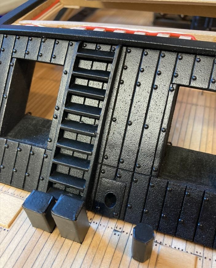
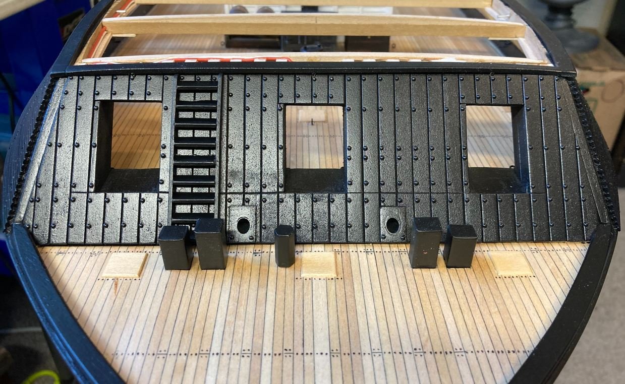
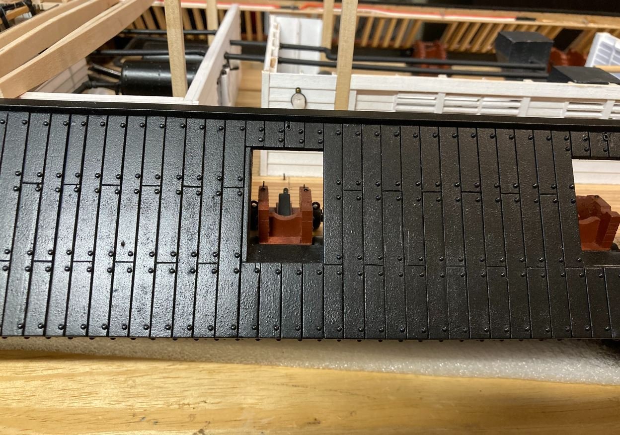
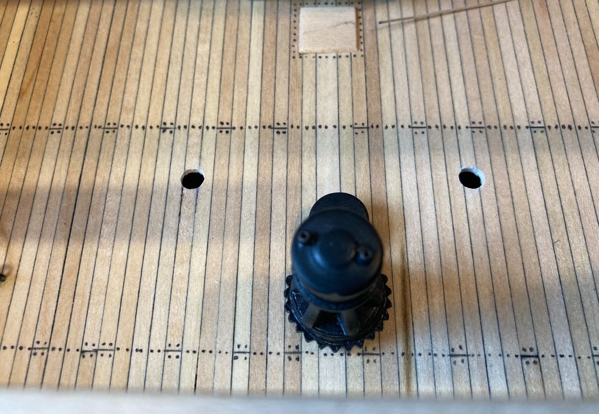
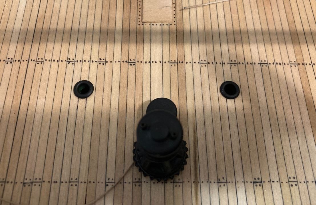
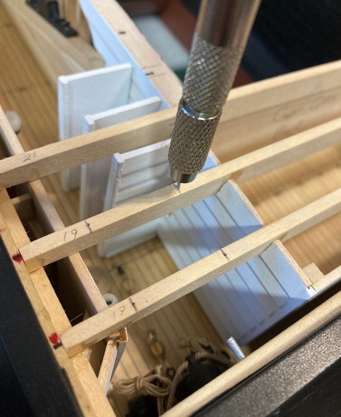
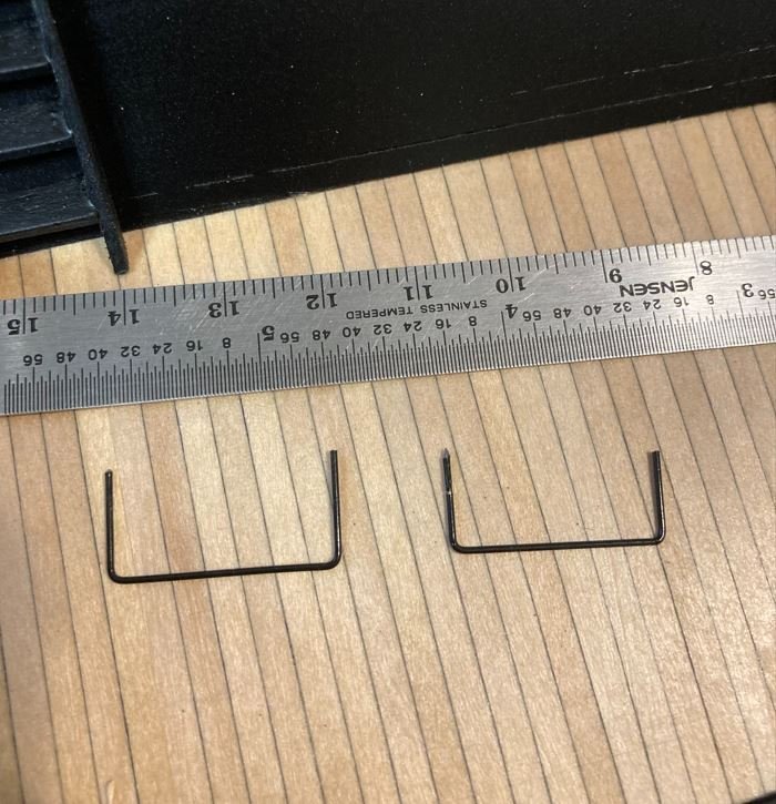
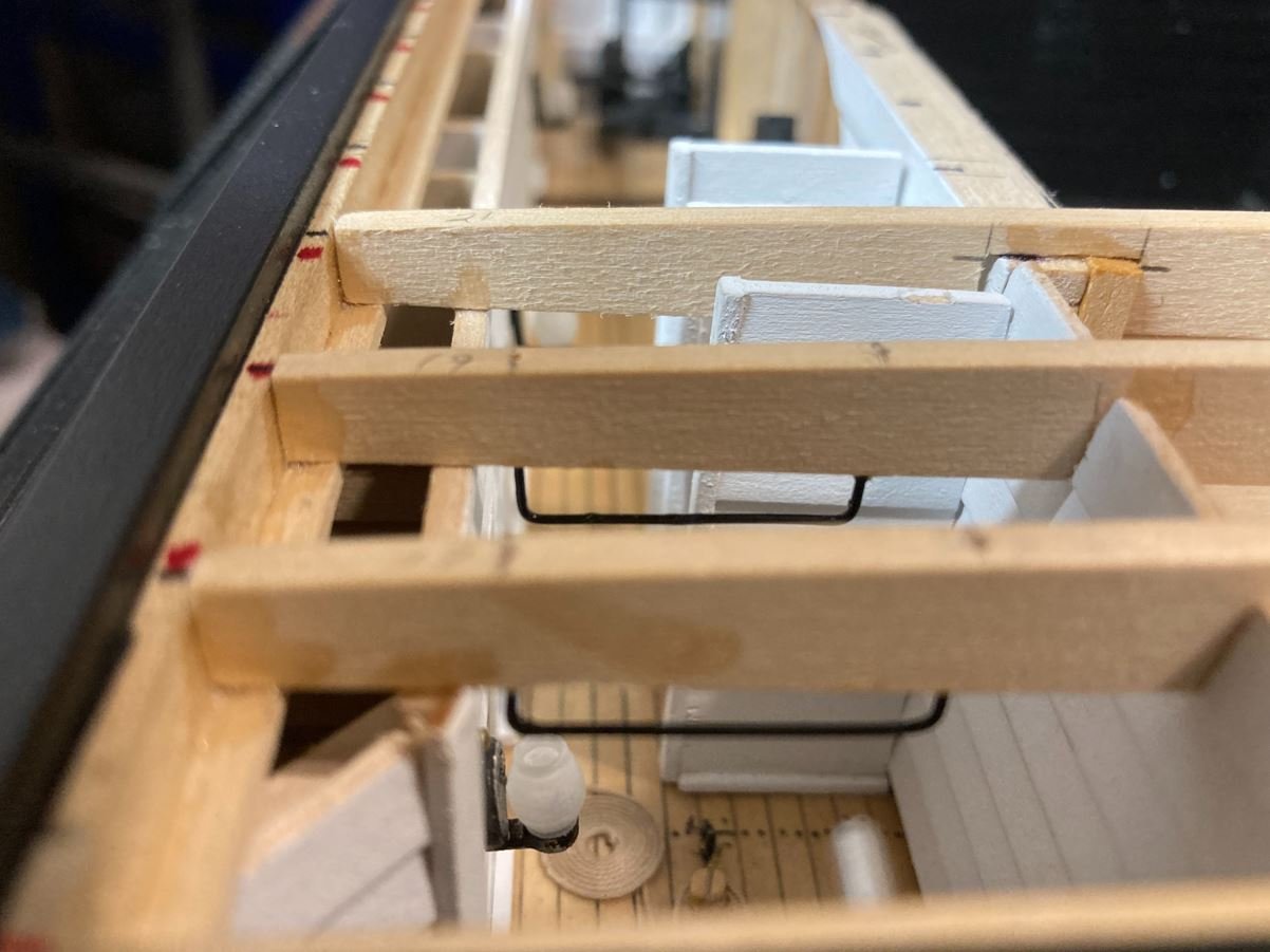
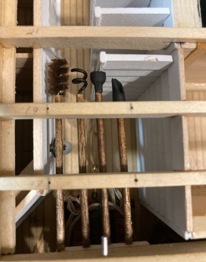
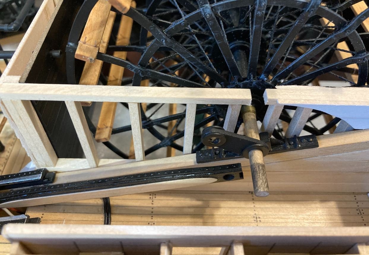
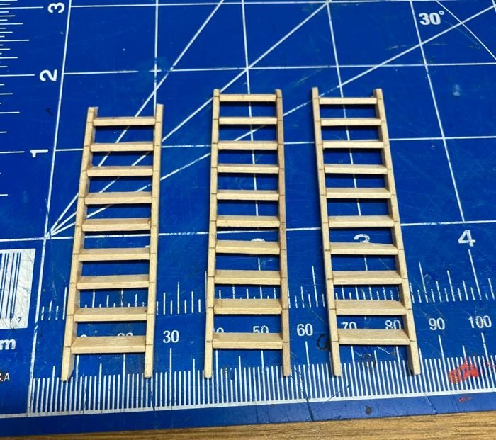
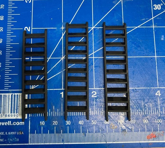
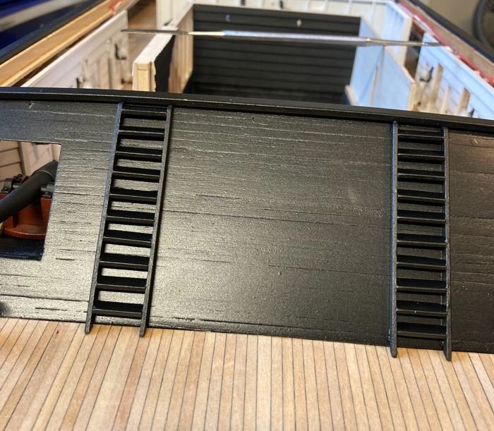
Hello everyone, Time again for another update. This time around I finished getting the aft 32-pound smoothbore in place and rigged. Here are a few shots of it going in Breech rope being seized.. Completed breech rope. Training rigging going in. And this cannon completed. I haven't been keeping track of the hours that I have spent on this build, but I do know that between the two aft cannons it took more than three hours to complete. These are some seriously tight quarters to get the hooks mounted to the eyebolts and the ropes drawn up tight. This task of the build has definitely swayed me from ever wanting to do a ship in the bottle build. Unfortunately, for all the work put into these, very little of it will be seen One of the smaller projects on this post was the completion of the paddle wheel crank. This was another instance of where I didn't take very many pictures of it being built. I have a bad habit of getting engrossed in these small pieces that I only think of taking pictures of them when they are done. Anyhow, here is the basic construction of the crank. Just a small piece of wood with two flat washers for the hubs. Once these were built up, they were painted black and installed. Next up were the exterior ladders. After reviewing all of the pictures of Cairo's sister ships, from what I can tell, she was the only one that just had ladders on the forward and aft casemates. All of the pictures of the other boats in the City Class show ladders mounted on the side casemates as well. Not sure if this was a later addition to the others or what, but since there is only one known picture of the Cairo in existence and there is not a ladder shown on the port side, it makes it very difficult to determine if the starboard side had one either. In studying the HSR drawings, there is also no indication of side ladders either, so I went with my best judgement and did not place any on the sides. And at the risk of sounding lazy, I am somewhat relieved I wasn't able to see any other ladders, because these are one feature of boat building that is not at the top of my fun list. This is only because they are so tedious and fragile, and I know it's just me, but I usually have a hard time getting all of the rungs lined up evenly. These were not as difficult as some of the smaller ones, but they are still ladders. Ladders glued together. Painted up Aft ladders in place. Forward ladder in place. and since I forgot to take a picture of the completed bollards in my last post, here is one with the forward ladder as well. Once the ladders were placed it was time to move on to more interesting features that will most likely not be seen, but I wanted to add just because it is a feature that I have never built on a model before. The "Head". I didn't want to devote a whole lot of time on them since they will be mostly hidden anyway, so I kept these structures simple. In reading up on the history of these boats, somehow they were able to channel the water off the paddle wheel to "flush" the heads and provide water for the showers. I did do some digging on this as well and was not able to find anything on it, so I decided to leave those details out. Next up, I started working on the roof beams. I needed to get some of these in place so that I could start placing the cannon implements. Once a few of the beams were in place I started on the rack for the implements. These were just made with some 20ga wire bent to shape. Holes drilled into the beams. Racks in place. ...and implements installed. There sure was not a lot of wiggle room to work around these aft cannons, it sometimes makes me wonder how often these aft guns were used. I'm guessing that the only time they would have been fired would have been during training exercises or when the enemy was crossing her stern or if the boat was in retreat and she was just protecting her six. Once the racks were in place, I continued on with more of the roof beams. Another small project that I completed were the interior hawse pipes. This was another detail that there is very little info on, and one that I added because I wasn't real sure where the anchor chain was stored. We do know that these boats had anchors because there is part of one that was destroyed when Cairo was torpedoed in the museum and there are hawse pipes mounted in the forward casemates. So I went with logic, and the limited knowledge that I have about anchor stowage and decided that if the capstan was used to haul the anchor, then the chain would have to be stored somewhere. So I figured that once they hauled the anchor in, the chain would be directed to the hold to keep it out of the way of the limited deck space available and free up space for the gun crews to move around without tripping over it. In my mind it all makes sense, and I couldn't find any info that would disprove my theory. So I ran with it. To continue with my thoughts on this, I figured the operation would work somewhat like this: the anchors would be weighed pretty much like any normal anchor. It would be pushed overboard and the chain let out until it hit bottom. The Western rivers were not known for their massive depths, and this was before they started dredging the river channels, so it most likely didn't require a lot of chain before the anchors settled into the mud. Once the crew was ready to get underway, heavy ropes with hooks were attached to the chain either at the bow, or just inside the forward casemate, the ropes were then wrapped around the capstan and the anchor hauled up. As the chain was coming up, the crew would direct it down the interior hawsers to it's storage locker until it was needed again. I may be way off base on this operation, but it sure sounds good on paper. If anyone has a better thought on this or actually knows how this was done, please share. The curiosity is killing me, and the info on this is very limited. So here are the holes drilled in the deck for the hawse pipes. and the hawse pipes installed. Next was the installation of the hog chain braces. Not a great bit of detail here. More to come on these later. Then it was on to getting this baby armed. I took a different approach to installing the port and starboard gun carriages since they were a little easier to access. The port carriages were easier due to the viewport opening in the side, which gave me access to the eyebolts through the casemate. I placed all of the carriages in their respective gun ports and then rigged them without the guns attached. Without the guns in the way I was able to get to the eyebolts better. However, it still took about an hour per carriage to rig up. After the rigging was completed, I went ahead and mounted the lower port doors. I wanted to get an Idea of what they were going to look like and how much the white interior paint was going to contrast with the black outer paint. It does stand out, but I think it looks alright. I studied the old pictures of the other City Class boats, but it is hard to tell in a black and white photo if these doors were painted white on the inside or if it is the sun reflecting off the black paint. In some instances, some of the boats look like the doors were painted black on the inside at one point. All lower port doors installed. I am going to hold off on installing the cannons and top doors for as long as I can. I don't want to risk snagging them and having to redo them while I work on the other features. I completed the rigging on all of the port carriages and moved over to the starboard side. This is where I am currently at so that will do it for this update. I am going to finish up on the rigging for the starboard carriages and get the lower port doors installed then work on installing and rigging the forward guns. Once these are completed I will install some gun deck details like the cannon ball crates, barrels and crew lockers. Until next time, thank you all for stopping by, liking and the kind comments. Please stay safe and healthy. -Brian
- 739 replies
-
- 19
-
-

-
-
You guys are good. I love and welcome the small talk. I find all these stories interesting and fascinating. Good to hear personal histories of fellow builders. -Brian
-
Roger, Quite the career you had there. Thank you for sharing and thank you for your service in the Navy. I am prior Air Force, but for some odd reason I have always had more interest in ships than planes. Never been able to figure that one out. 🤷♂️ -Brian