HOLIDAY DONATION DRIVE - SUPPORT MSW - DO YOUR PART TO KEEP THIS GREAT FORUM GOING! (Only 20 donations so far - C'mon guys!)
×


mbp521
-
Posts
1,002 -
Joined
-
Last visited
Content Type
Profiles
Forums
Gallery
Events
Everything posted by mbp521
-
 Beautiful job Russ. She really came out great. Congrats on her completion. -Brian
- 23 replies
-
- 2
-

-
- model shipways
- chaperon
- (and 1 more)
-
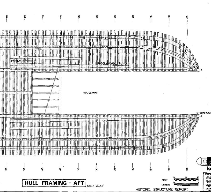
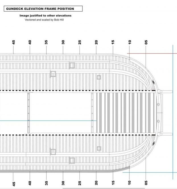
Hello everyone, I know we may have beat this horse to death, but the subject has been on my mind and I wanted to throw this out there to any future City Class Iron Clad builders. As Roger stated before, the plans that I have are wrong. With that being said, here is what I discovered after reviewing my source material. The Bob Hill plans are the ones that are wrong. His plans plans have the chine turning into the outboard keels and terminating a couple of feet forward of the stern post. This is the way that I built my model the first time around. I used these plans since they were a lot clearer than the HSR plans. I didn't think to do a side by side comparison of them, taking for granted that I thought the Bob Hill plans were correct. Bob Hill Plans. The drawings in the HSR are correct where they have the chine turning into the outboard keels and terminating at the stern post. There are several other noticeable differences that I have discovered as well between the two plans and now I am going back and making several adjustments to my build because of them. I'll point them out in later posts. But, since this was on my mind I figured I'd post it now. I have still not gone back and looked at the step-by-step documentation the USS St. Louis build to see if they pointed this issue out, so if anyone else has looked and found that they have mentioned it, then please forgive my duplication of info. -Brian
- 739 replies
-
- 12
-
-
Roger, This is what I would like to to, but since my planking at the bow didn't quite line up it would still be noticeable even after the hull was painted. Something that would bother me every time I looked at it (just the way my little OCD pea brain works). My thoughts on what you are saying about no longer matching the drawing dimensions would be this: The original hull planks were about 3" thick using the scaling from the plans which equates to about 1/16" (the thickness of the planks that I used) scaled down to 1:48 . The veneer planks that I have ordered are .020" or just a smidgen over a 1/2 mm thick which would be roughly 1" scaled up. I figured that during the sanding to fair the hull, I'm almost sure that I took at least that much off of the original planking for the veneer to make no more than a 1/2" difference at most in the overall width of the boat. At least this is what my crazy math calculates to. Then again my math has been known to be wrong. -Brian
-
Mark, I actually did glue them down wet on the port side. This was my first mistake. One that I didn't make on the starboard side. I had glued down the curved portion where it mounts to the solid filler blocks and in my haste to get them done (second mistake), went ahead and glued the rest down to the bulkheads before letting the planks dry. On the starboard side I let them dry first then glued them to the bulkheads. No gaps on that side. Another lesson learned. I need to heed your signature and slow it down a bit. -Brian
-
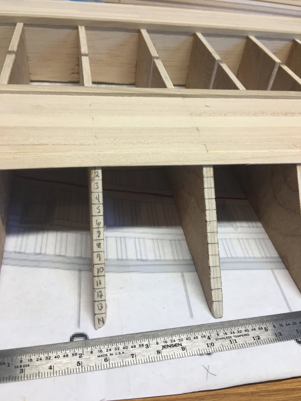
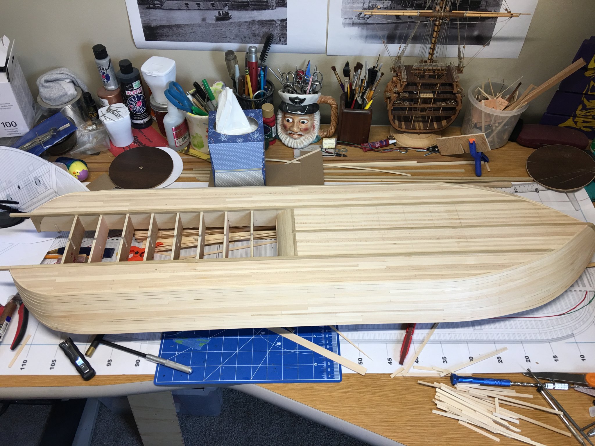
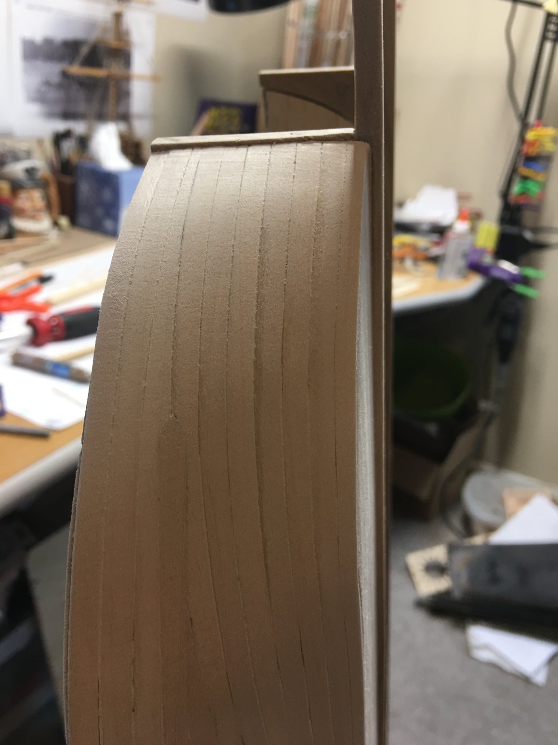
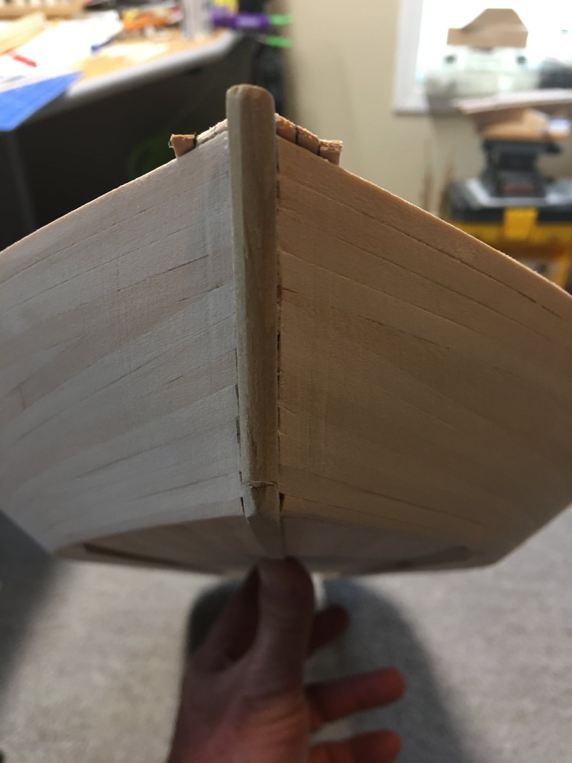
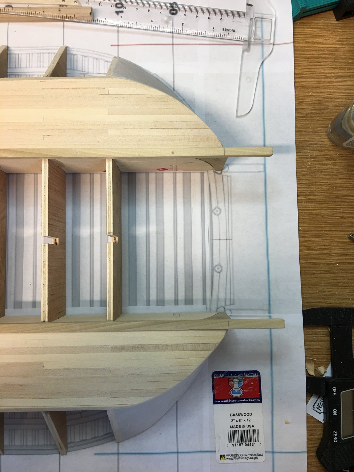
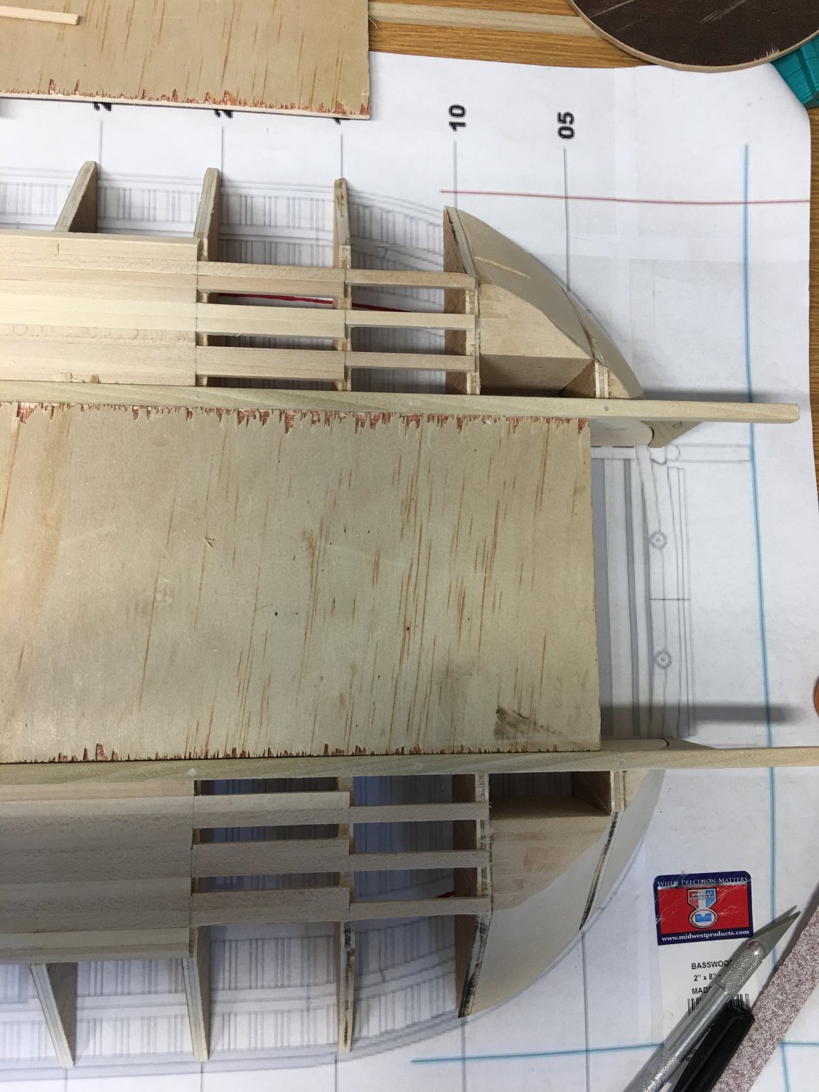
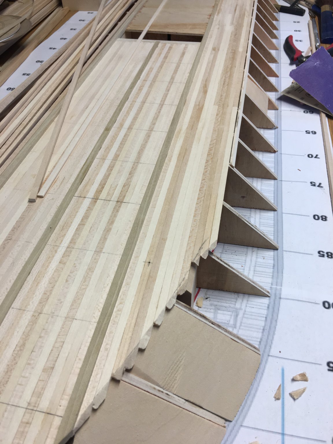
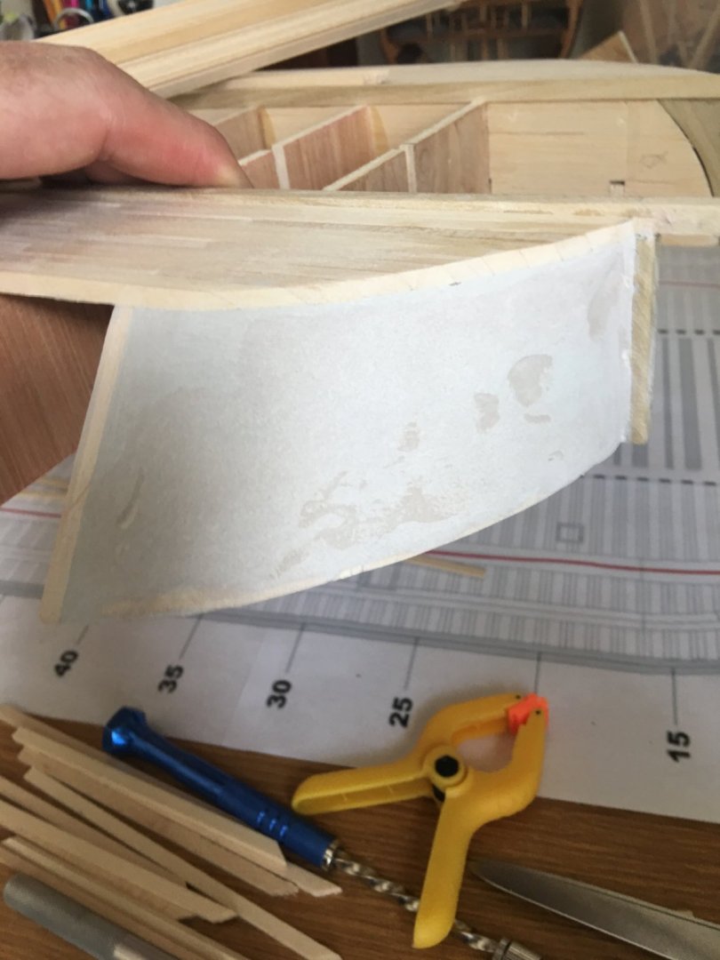
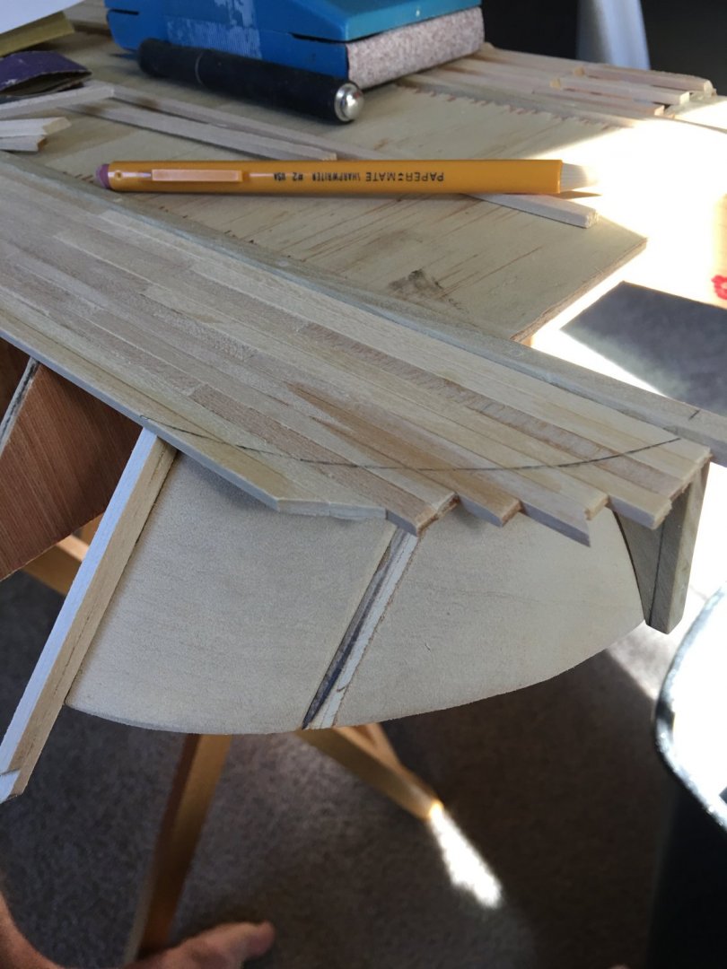
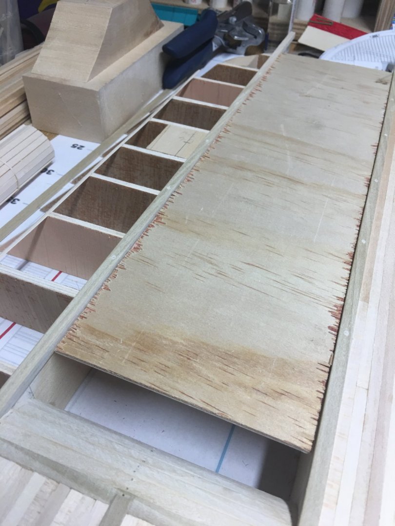
Hello again everyone, It's been slow going on the build this week. The side hull planking is taking more time than I was expecting. The bow section was pretty easy since the curves are a lot longer with less twists in a short span but the compound curves on the aft end of the hull proved to be pretty complex in getting the bends just right. Initially my plan was to single plank the hull sides, but with the way the turns are on the aft end I needed to soak the planks to get them to cooperate, and once they were in place they shrunk up when they dried. This left several noticeable gaps that I don't think would look right just filling them in (even with the hull painted). All this coupled with the fact that I struggled to get the planks to line up just right at the bow for one reason or another, led to my decision to go with the double planking. The side planks are 1/16" x 3/16" strips so I am going with .020 x 3/16" basswood veneer strips to lay over them. this shouldn't throw my scaling off too terribly much. Plus, the thinner strips will be a lot easier to bend and line up. In the scratch build world, I'm not sure if this is cheating or not going with the second layer of planking, but I want this build to look as real as possible, so cheat I must.😈 Here are some of the pictures of my progress this week. Laying out the first couple of runs of planking. My measurements didn't come out quite right and I ended up with one thin plank (about half the width of the others) in the middle. I am going to have to go back and redo my calculations, because I should have had exactly 14 - 3/16" planks along the sides. Completed side planking. Notice the gaps at the aft end where my planks shrank back when they dried. Aft planking after rough sanding. This part turned out pretty good. My guess is that since this area had a solid mounting surface underneath, the planks couldn't shrink up enough for a gap. Since the ones around the side were just glued to the bulkheads they had room to separate. And the bow planks misaligned. I am a little disappointed in this part so far, but I will get it fixed. The veneer is on order and should be in some time this week. In the meantime I will start work on the decking. Hopefully once the veneer planks arrive and I get them installed, I will have better pictures to show. We shall see. Anyhow, Thank you for looking. -Brian


- 739 replies
-
- 10
-
-
Vaddoc, I believe you are right. I’m satisfied with the results. Time to start planking. -Brian
-
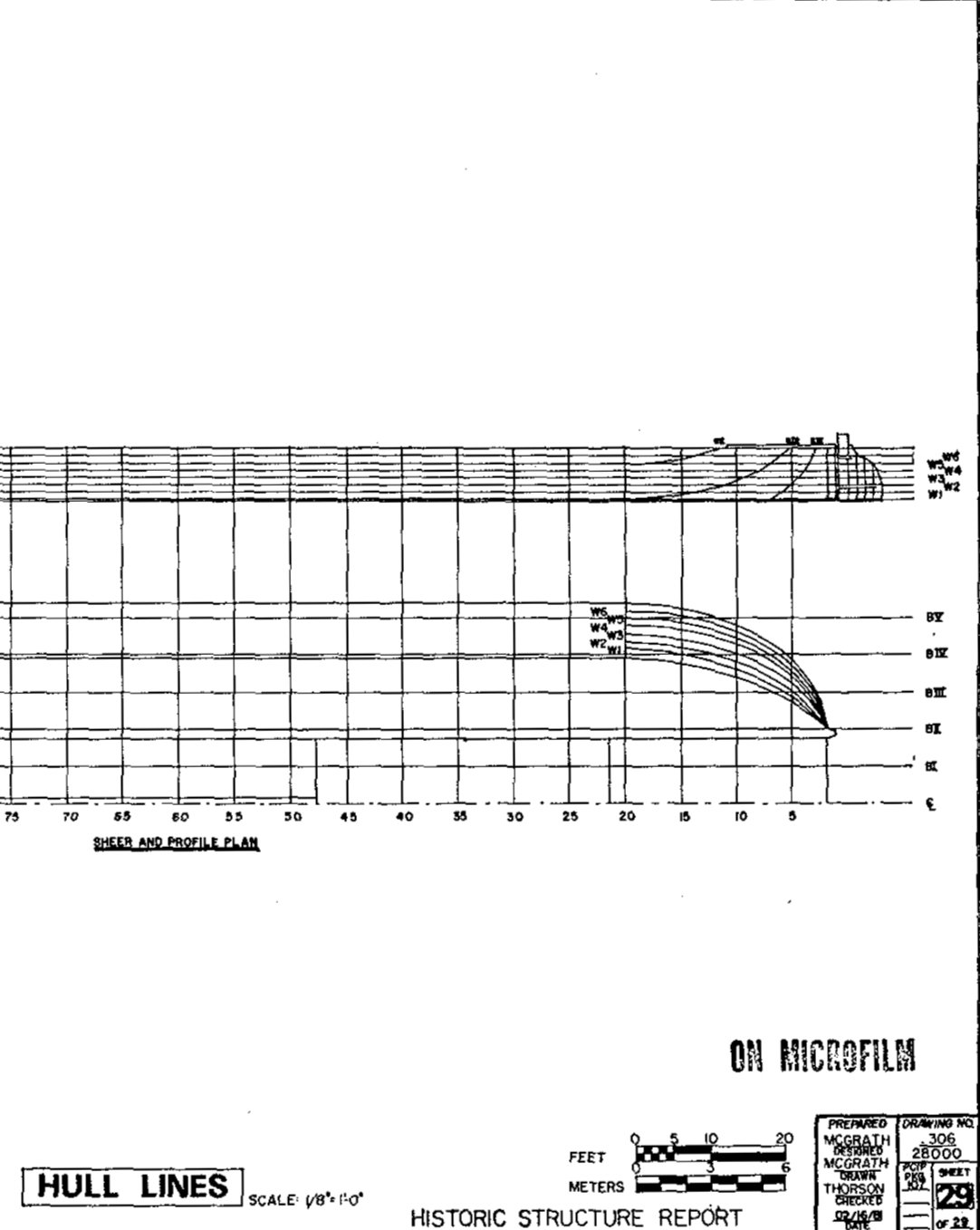
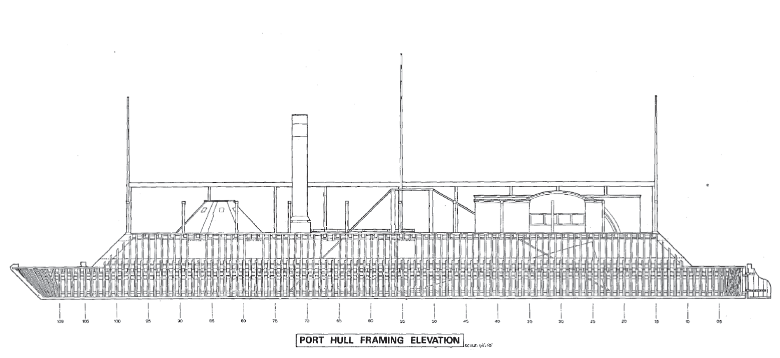
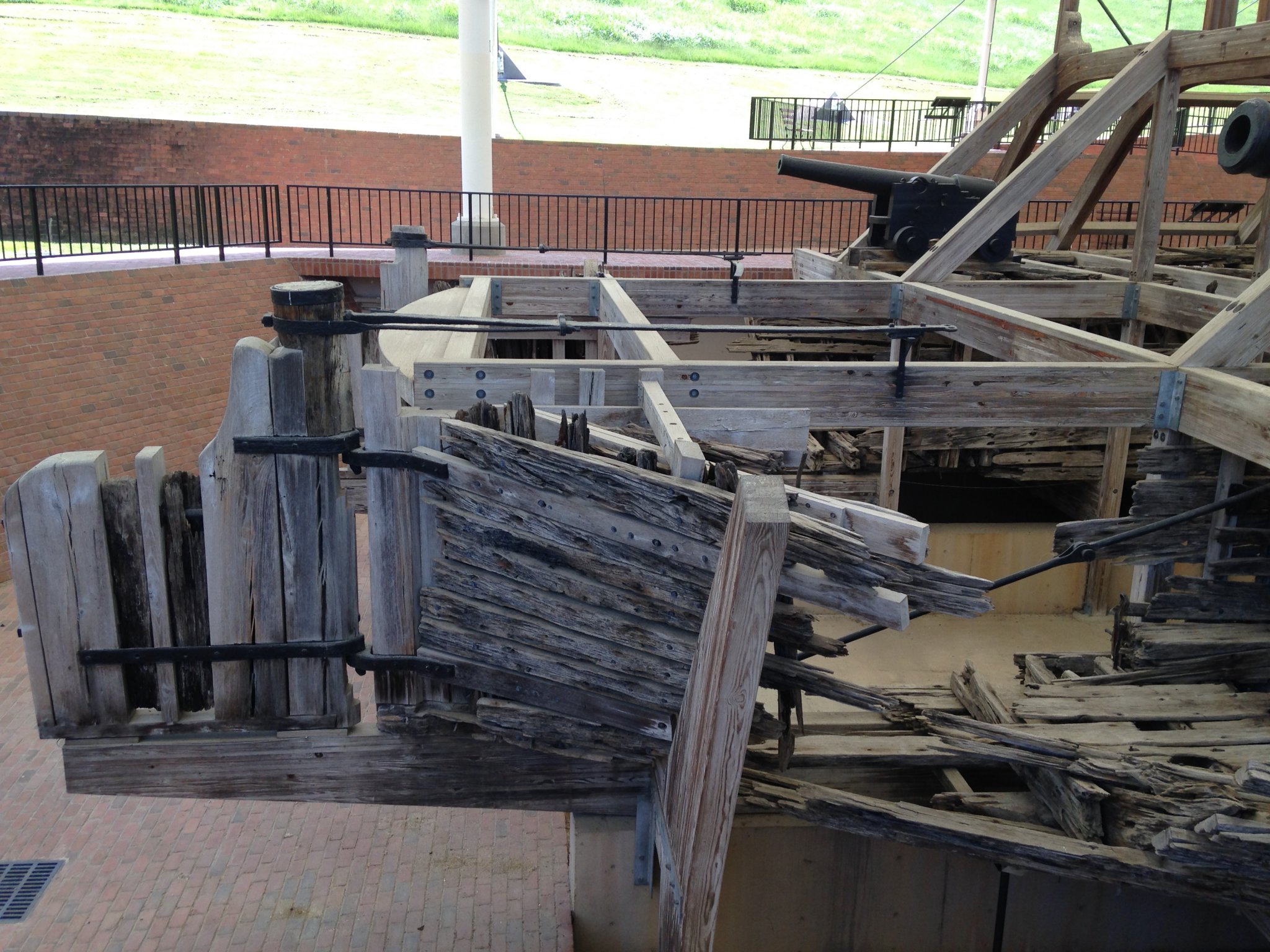
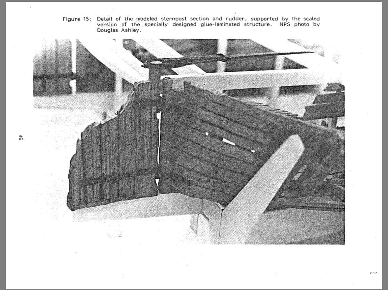
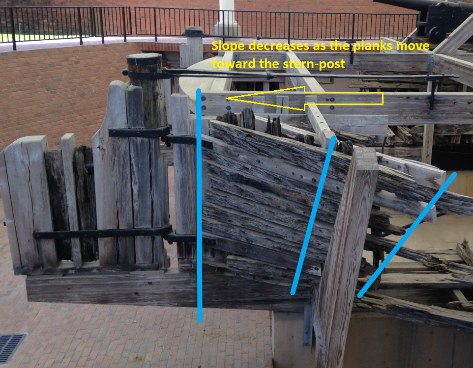
Roger, That is totally odd that the drawings would be that much different. I went back and reviewed my copy of the HSR and they are definitely different from those they are using on the St. Louis build. I also noticed that that I am pretty much on track with the contours of the stern judging by the below pictures. This is from the HSR and show the model of the mock up for the permanent display. It clearly shows the vertical terminus of the hull planks against the stern-post. The second picture is also from the HSR showing the hull lines. The hull lines of the sheer definitely get tighter as they come around the sides to the stern-post. I am going to go back and review where I downloaded the plans from to make sure I have the correct copy. I know it wasn’t from the NPS website. I’m thinking it was from the Vicksburg NMP website but I’m not for certain. I’ll pull down an additional copy from the NPS and do a stare and compare to see if there are any other differences. -Brian

-
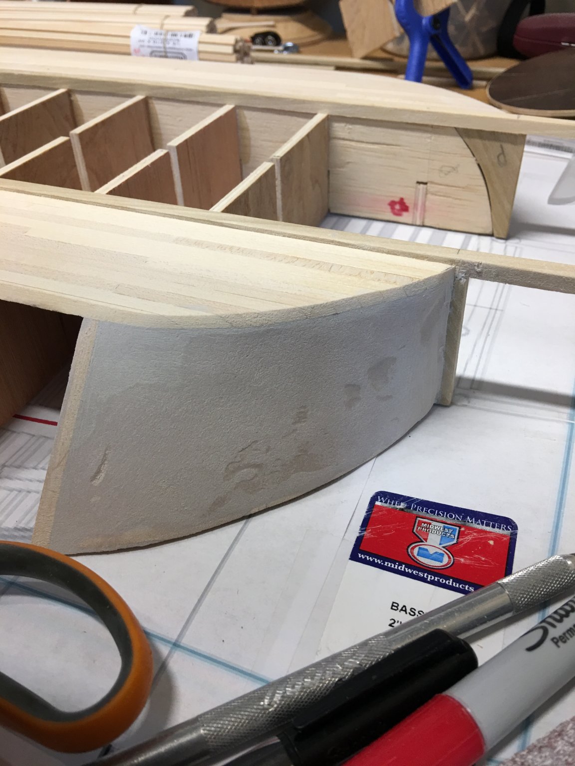
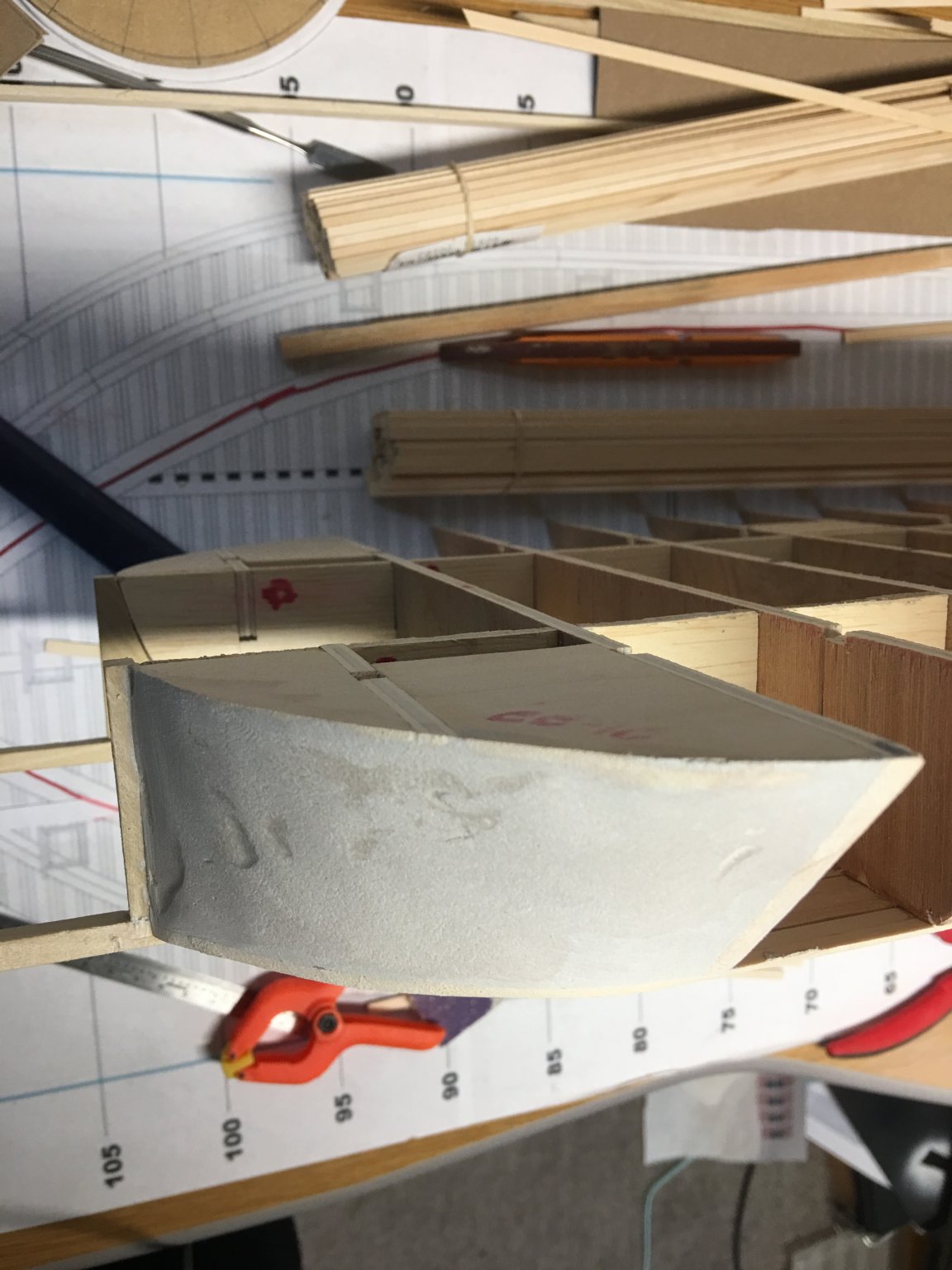
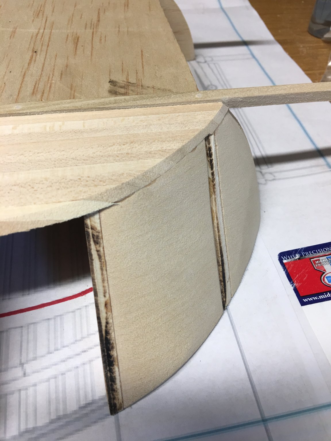
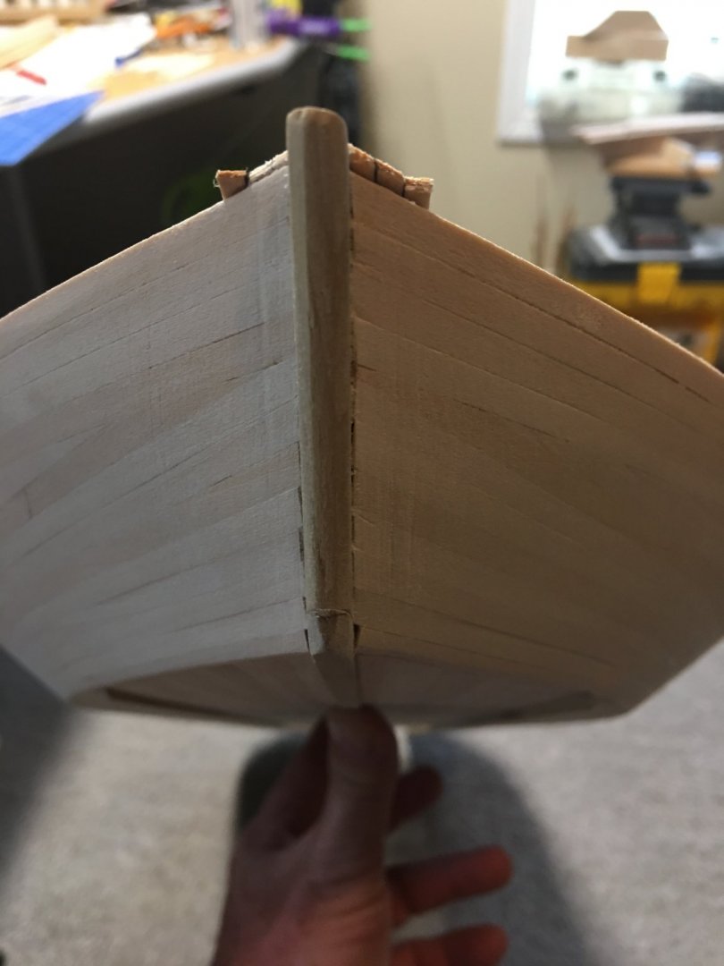
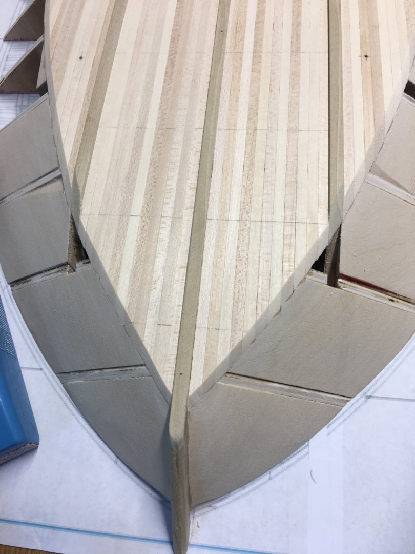
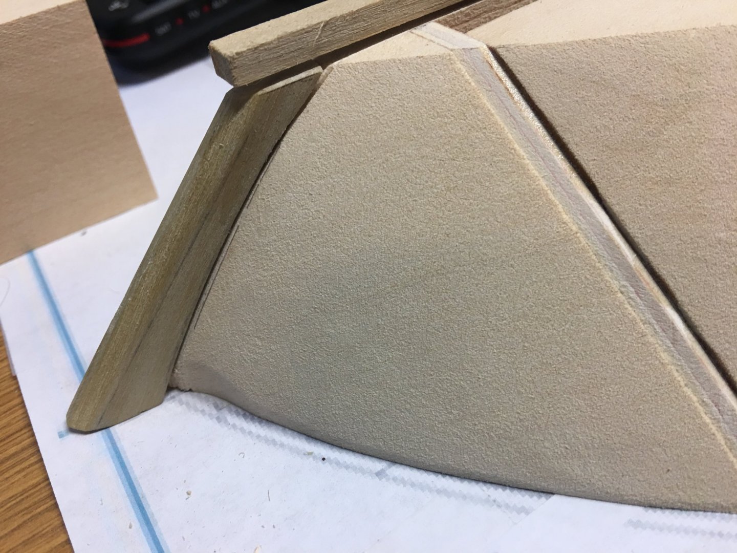
Roger, No heartburn caused here, This is most definitely a learning experience. All the input you all provide helps me along the way to a successful build. While I am by no means an expert model shipbuilder, the more accurate I can make this build the happier I will be and I will take all the advice I can get to make it as accurate as possible. With that being said, this is the solution that I came up with. I am hoping it is somewhere in the ballpark of what the actual boat looked like. So I finished up the planking on the port side, trimmed the planks and applied a generous amount of body filler to the newly created void. I sanded the filler to the contour of the hull planks and the deck line and I think the result came out looking pretty good. The chine is now in line with the green line I had outlined on the plans and the terminus at the stern-post is vertical. Please for give the multiple photo angles, I am by no means a photographer and it is hard to get the right angle that shows the curve and the taper at the same time. I think I will apply one more thin coat of filler to catch the small pockets that I can now clearly see in the pictures, but otherwise I think I should be good to go. Thoughts and comments on this are more than welcome. -Brian


- 739 replies
-
- 12
-
-
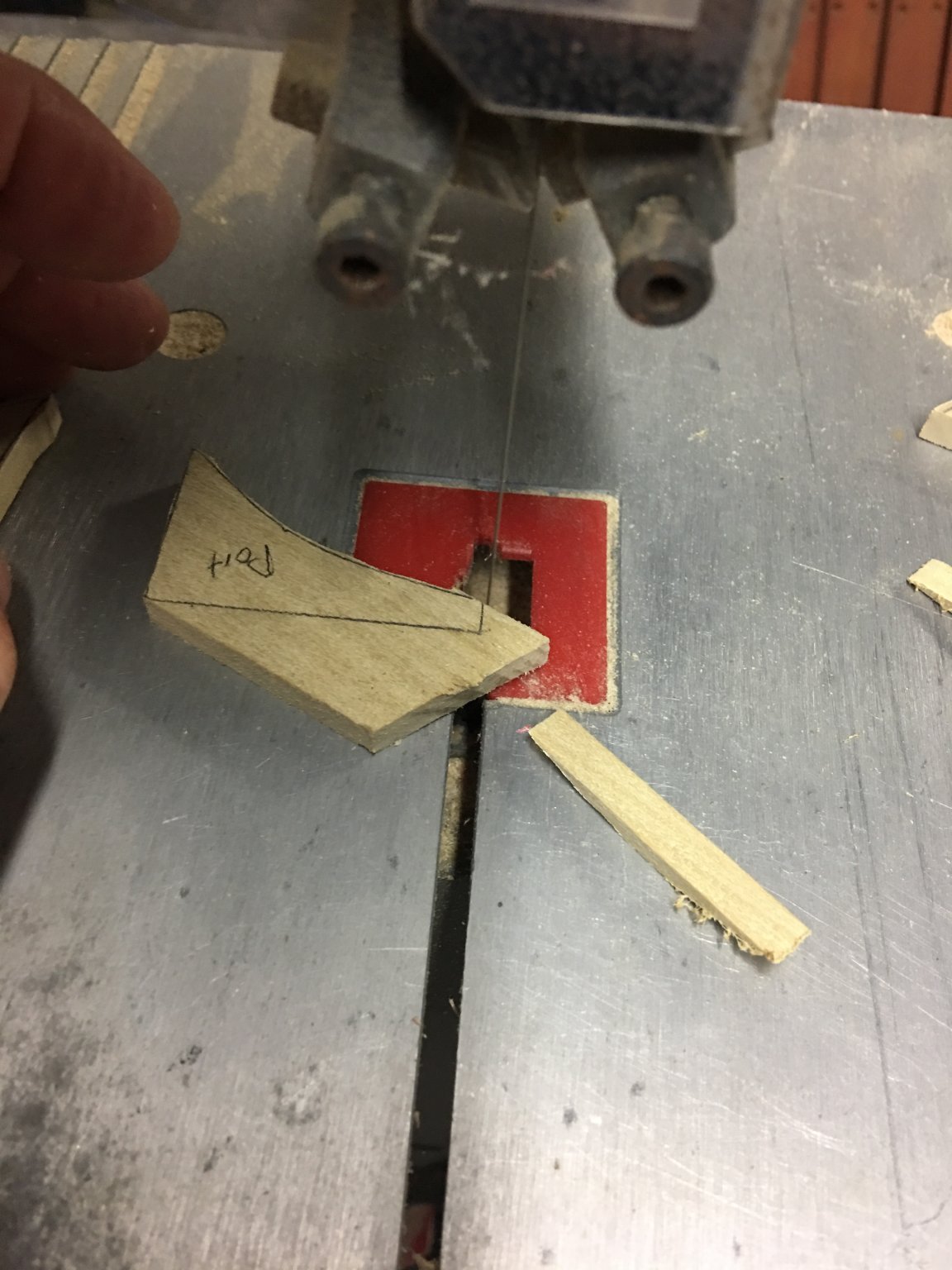
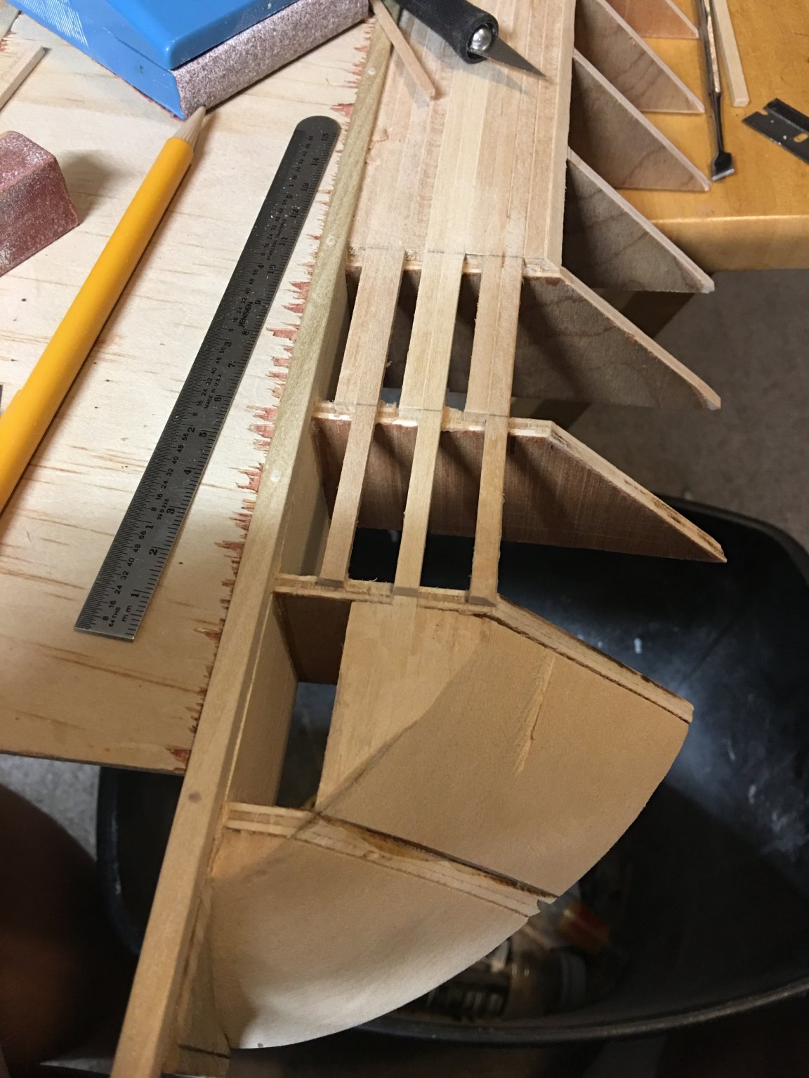
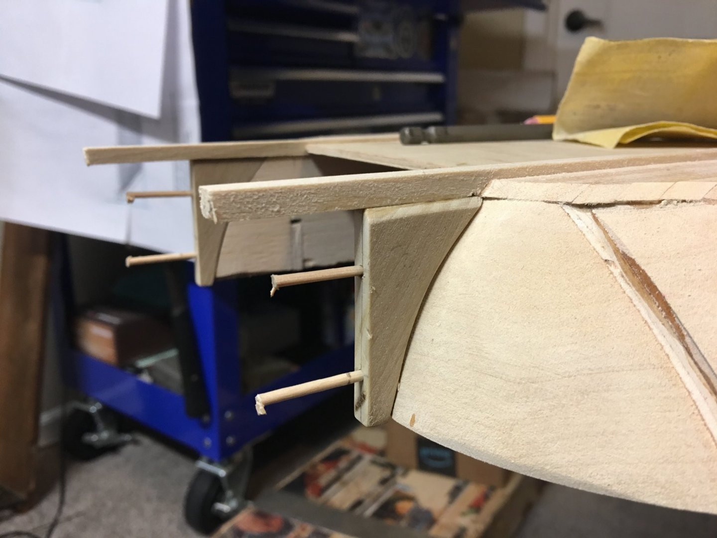
Roger/Vaddoc, Thank you for the input on this. I figured the plans were wrong, of course it had to be after I had already got part of it built out. However, since I have been pondering this issue I think I may have it figured out a solution. So first thing I did was to cut out new stern-posts so they would be in the correct vertical position. I then installed them and used trenails to help hold them in place. Then I went through and removed the hull planking in order to lengthen them to the correct chine (thanks Roger for the terminology). Then here just a few minutes ago I reinstalled the planking to the new chine on the starboard side. I had to build up the bulkhead at station 10 on the plans since the bottom has been extended and is now wider than it was previously. I will taper these built up areas toward the top so the width on the deck does not change, only the hull. This new line should provide me with the (hopefully) correct contour. Tomorrow I will finish up on the port side planking then I'm going to try filling in the newly created gap with some body filler and see if this will give me the look I am hoping for. Fingers crossed this works. If not, I'll have to tear it all down and try again. -Brian


- 739 replies
-
- 14
-
-
I believe you are correct. The slope gradually decreases as it comes around from the sides and at the point it makes contact with the stern-post it is pretty much vertical. -Brian
-
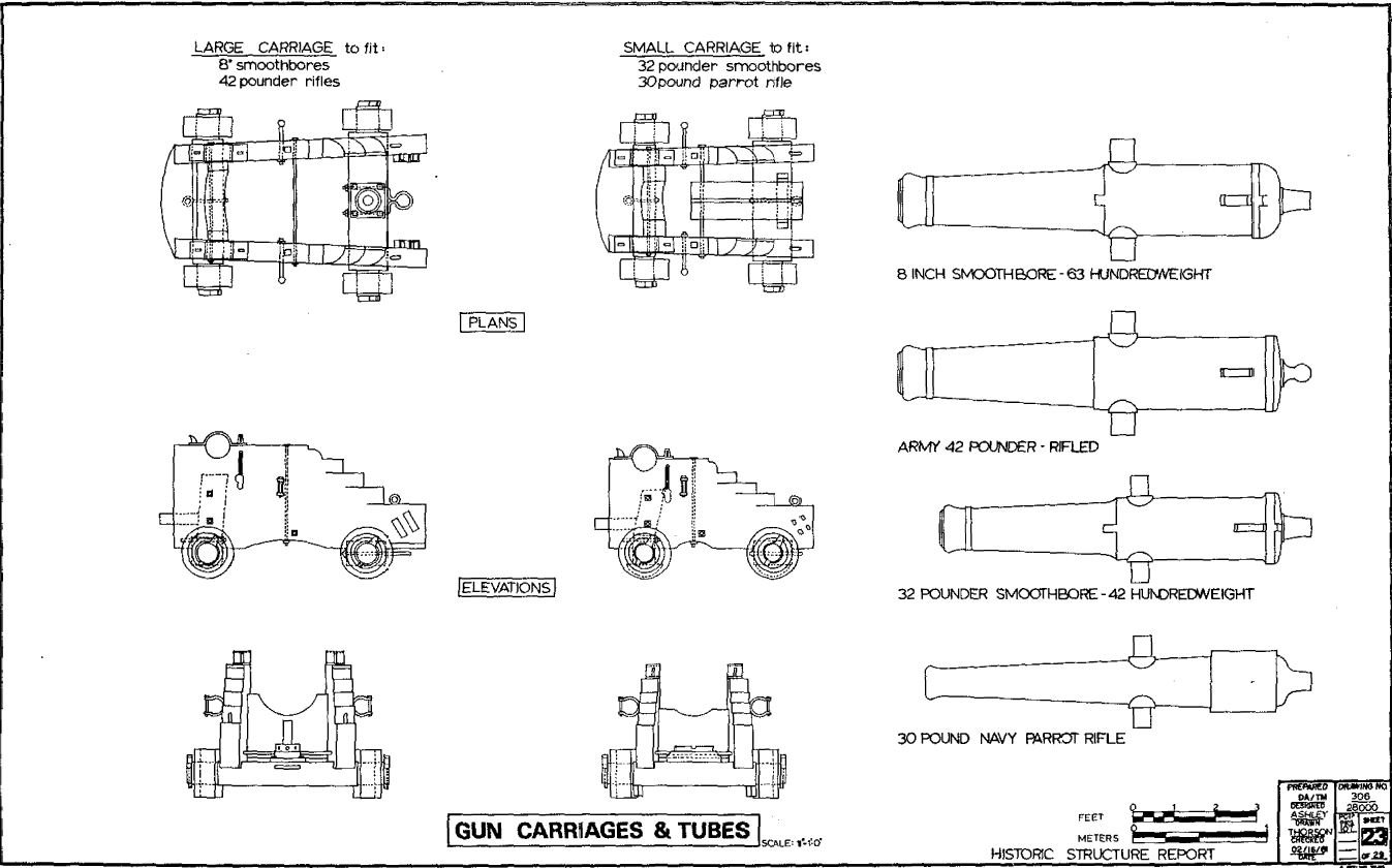
Vaddoc, Here are the ones you pointed out. The upper right is the cannon details and the second is the Port side framing elevation. See if these will work, if not PM me and I can send you the entire Historical Structure Report PDF. -Brian

-
Kurt, I did mention that one, and you are correct they have found numerous errors with the Bob Hill plans. I perused through this build several times to see what they came up with on how the stern of the boat was built. Unfortunately there is not a whole lot of detail in the build log itself and the pictures are limited. I have yet to go through their documentation that they have available to see if the details are there. These may provide some useful insight. - Brian
-
Thank you Yves. I like the scale and thought it would be neat to show a size comparison between a work boat and a war boat. -Brian
-
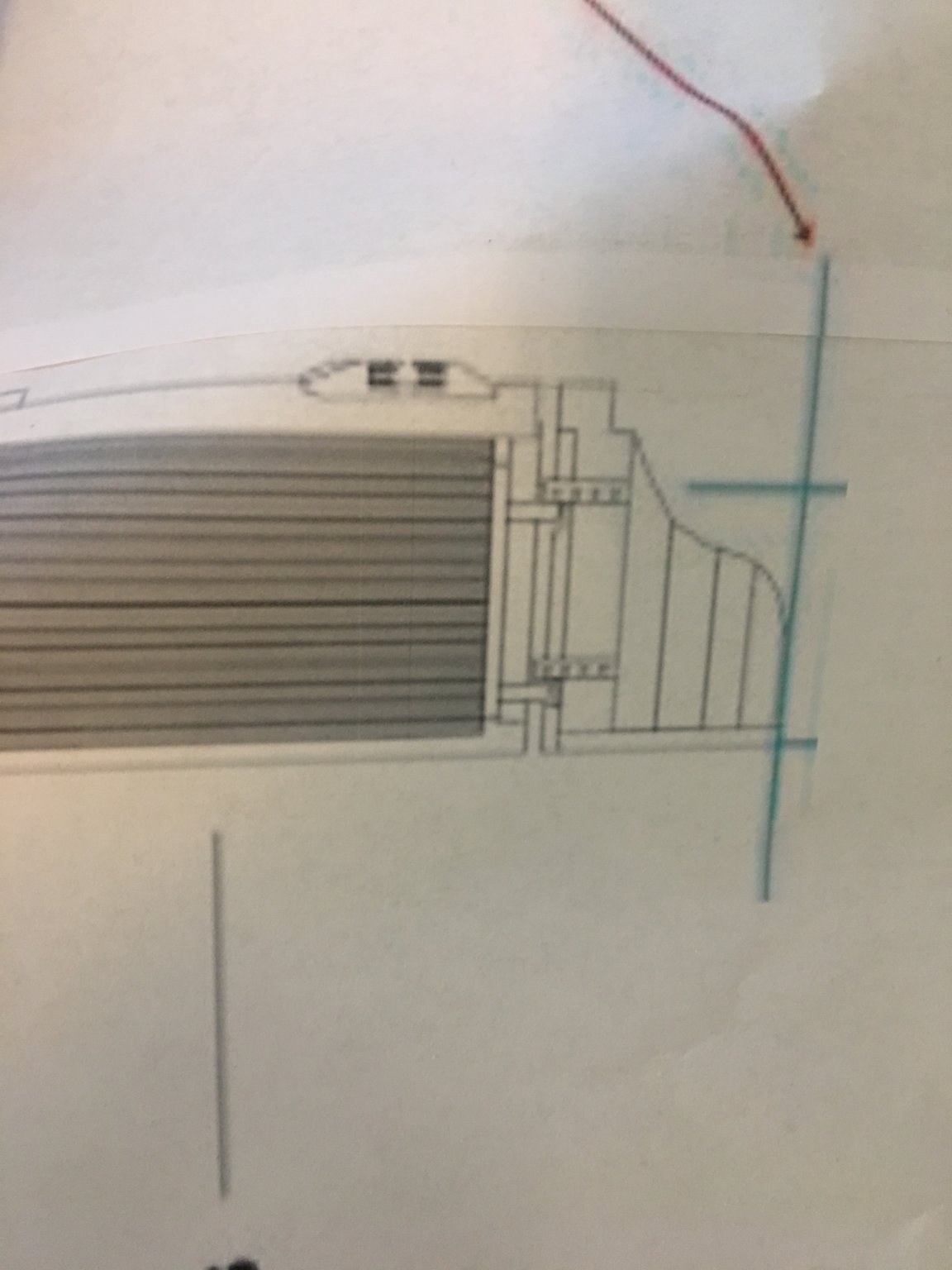
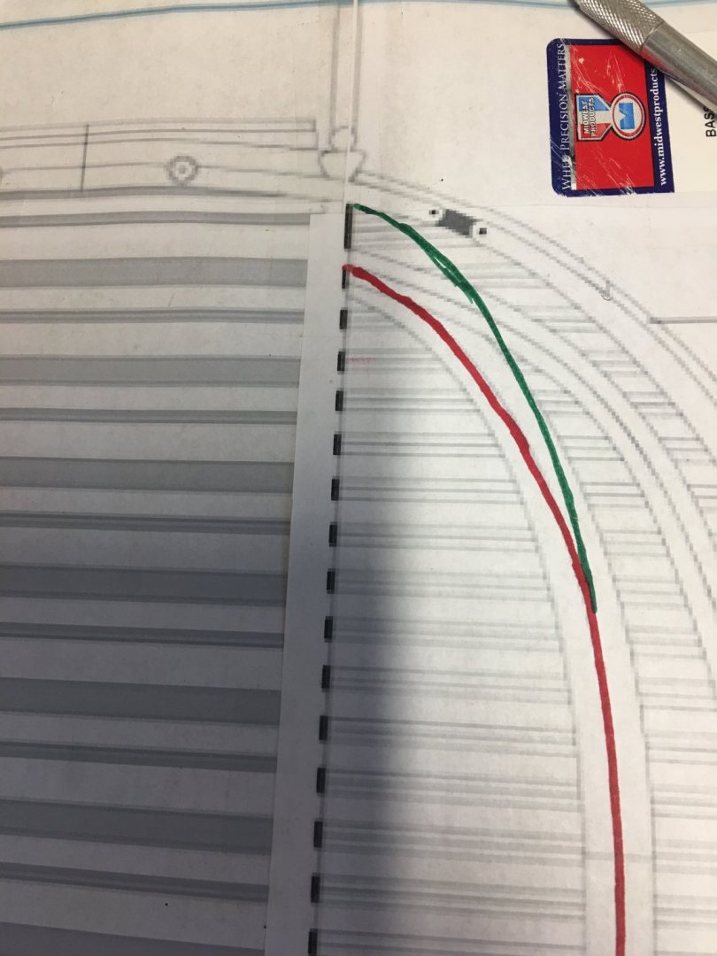
Vaddoc, Those are my intentions to try and get the compound curve right. The radius of the curve is tight going from a vertical 90° angle to an angle of about 43° angle in a short distance. I have a plan that just may work to get it corrected. I will move the hull planks to the same line as the upper deck planks (the green line on my previous post), change the angle of the last two bulkheads to compensate for the lengthened hull planks and fill the void with body filler. If I can get a nice smooth edge with a putty knife, running it along the top edge of the filler blocks and the edge of the extended hull bottom planks, the body filler should form the correct angle transitions from the stern-post to the hull sides. This is the plan, anyway. We'll see how it works out. I'll be sure to post pictures of my progress. - Brian
-
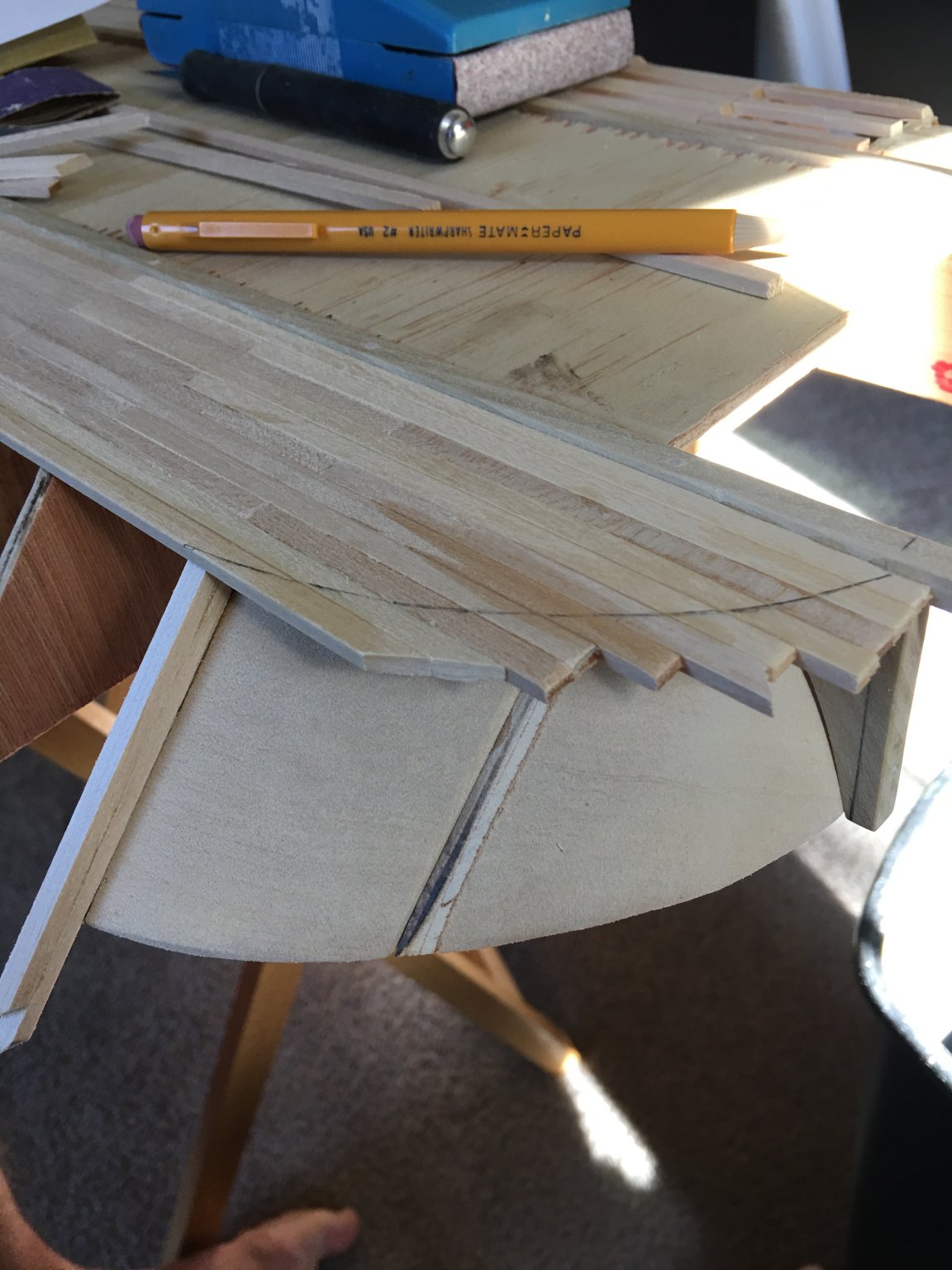
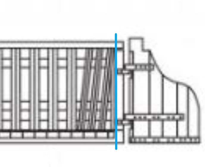
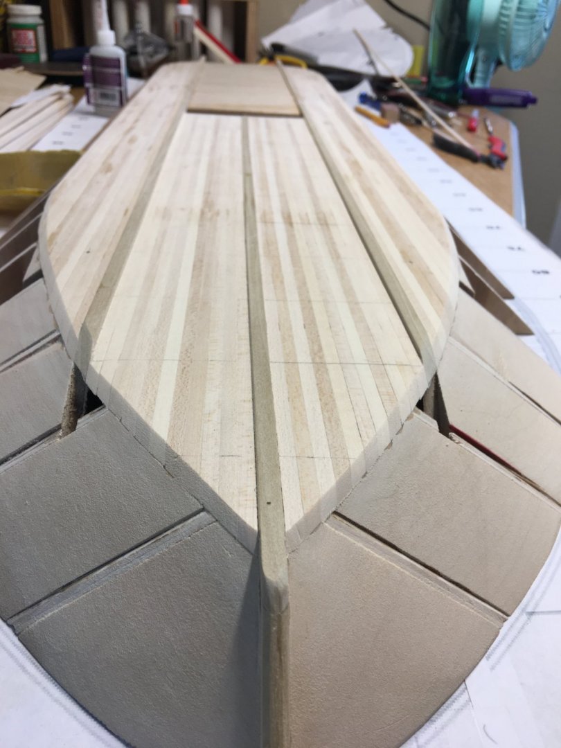
Hello again everyone, Time again for another update. So things were moving along pretty smoothly. I finished planking the Starboard side of the hull bottom. And then completed the planking of the port side bottom. Once this was completed the ends of the planks were trimmed and sanded smooth to blend with the filler blocks. It is at this point where I ran into my first real snag. It was while I was sanding the aft filler blocks and hull planks when I noticed that the contour of the hull didn't seem right. According to the hull plans, the flattest part of the hull bottom should follow the red line (as drawn on the plans), and this is how I built it. In looking at this view the flat bottom of the hull would stop about a half inch shorter than the bulwarks at the top of the deck. This would create a slightly curved stern-post at the back end of the false keel. However, if you look at the elevation plans the hull side planking runs straight up and down at the stern-post and rudder. This is also visible on the actual ship. So I determined that the hull bottom should curve more like the green line drawn on the plans, creating a more 90 degree angle on the false keel and stern-post. I'm not sure if I am just misreading the plans, or if there is truly an error on them. This is my first scratch build, so I could have just totally misinterpreted the plans, but following the red line all the way around seems to line up perfectly with the hull bottom with the exception of the aft end. So, in order to make it look right, I'm thinking I will need to extend the hull bottom out to the green line and add some more filler to get the proper contour of the hull. Please feel free to chime in if I am way off base. ...anyway, time to make some more sawdust. Thank you for looking. - Brian


- 739 replies
-
- 12
-
-
Thanks for the pictures Eric. Those are two top quality builds to be proud of. -Brian
- 599 replies
-
- 4
-
-
- sidewheeler
- arabia
- (and 4 more)
-
Eric, She looks great sitting there in her place front and center in the room. Great place for her. I’d love to see a picture of her sitting next to the Bertrand. Even though they are different scales, it’d be a neat photograph. Here’s hoping your stress levels go down in the next few weeks. Best of luck on your in-laws move. Really looking forward to your Longship build. -Brian
- 599 replies
-
- 4
-
-
- sidewheeler
- arabia
- (and 4 more)
-
Vaddoc, She is indeed big and unusual. Her the characteristics and her history are what draw me to build her. That, and the fact that there aren't many American Civil War Iron Clad builds out there. These boats were pretty much built for patrolling inland rivers and bombardment of forts. They weren't designed for open water. The waves of the sea would probably swamp them in a second, given the fact that their decks were just inches above the waterline. The sloped sides were set up to deflect enemy fire from cannon and bullets. This is one of the reasons their opponents changed tactics against them and started lobbing cannon balls at them since the sides were the only parts that were armored. They would attack from the top and the cannon balls would penetrated the more vulnerable decks. This particular ship was actually sank by torpedo, or in modern terminology, a mine that was triggered remotely which penetrated her unarmored hull and caused her to sink in 12 minutes. Fortunately, all of the crew made it out alive. -Brian
-
Four points definitely makes sense. This will be the first time I’ve done it this way. My KotM and Chaperon are two pointed but they sit flat on their hulls and the anchor points just hold it in place. For this one I want it to sit above the base to give a better view of the unique hull design. Thank you Keith. I feel these types of ships have somewhat been forgotten in the model building world and hopefully building her will spark an interest in them. -Brian
-
Magnificent results Eric. She came out looking stunning! I'm sorry to see you have finished her because that means an end to this wonderful build log. I've picked up so much knowledge of the steam era as a result. I am now chomping at the bit to see what your next project is. Don't keep us waiting too long. -Brian
- 599 replies
-
- 5
-
-
- sidewheeler
- arabia
- (and 4 more)
-
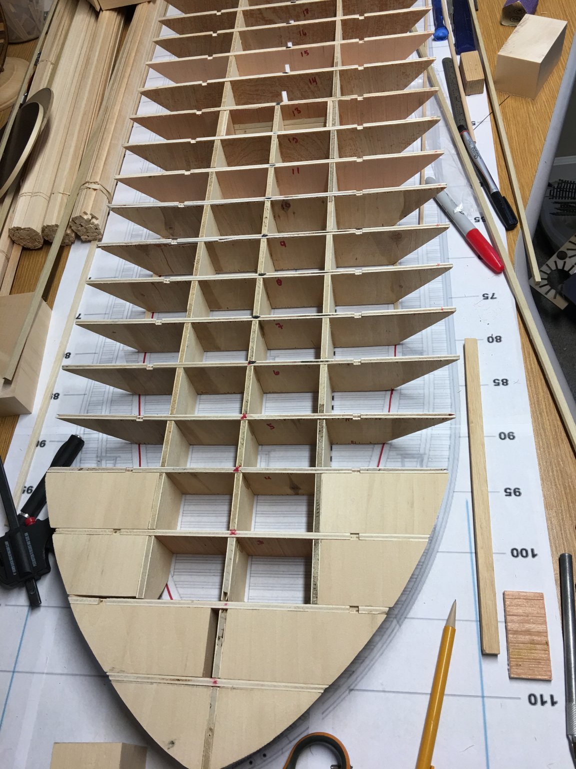
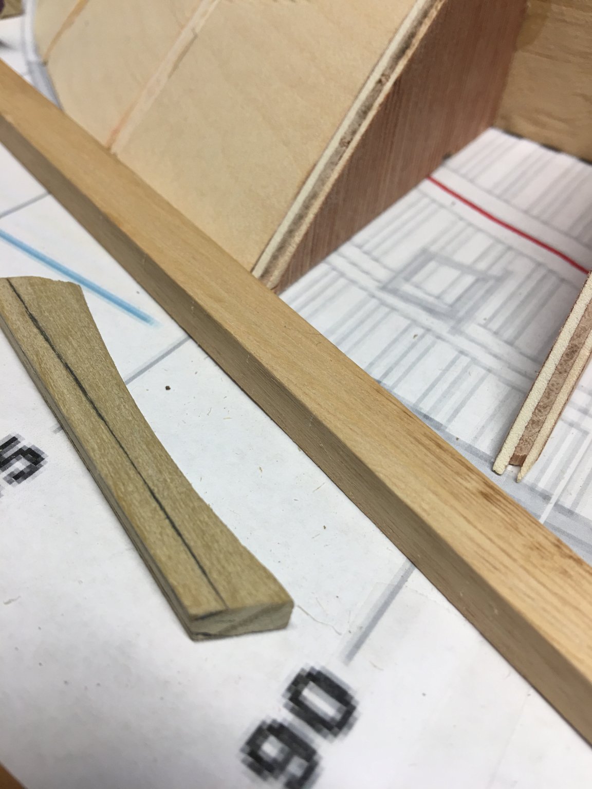
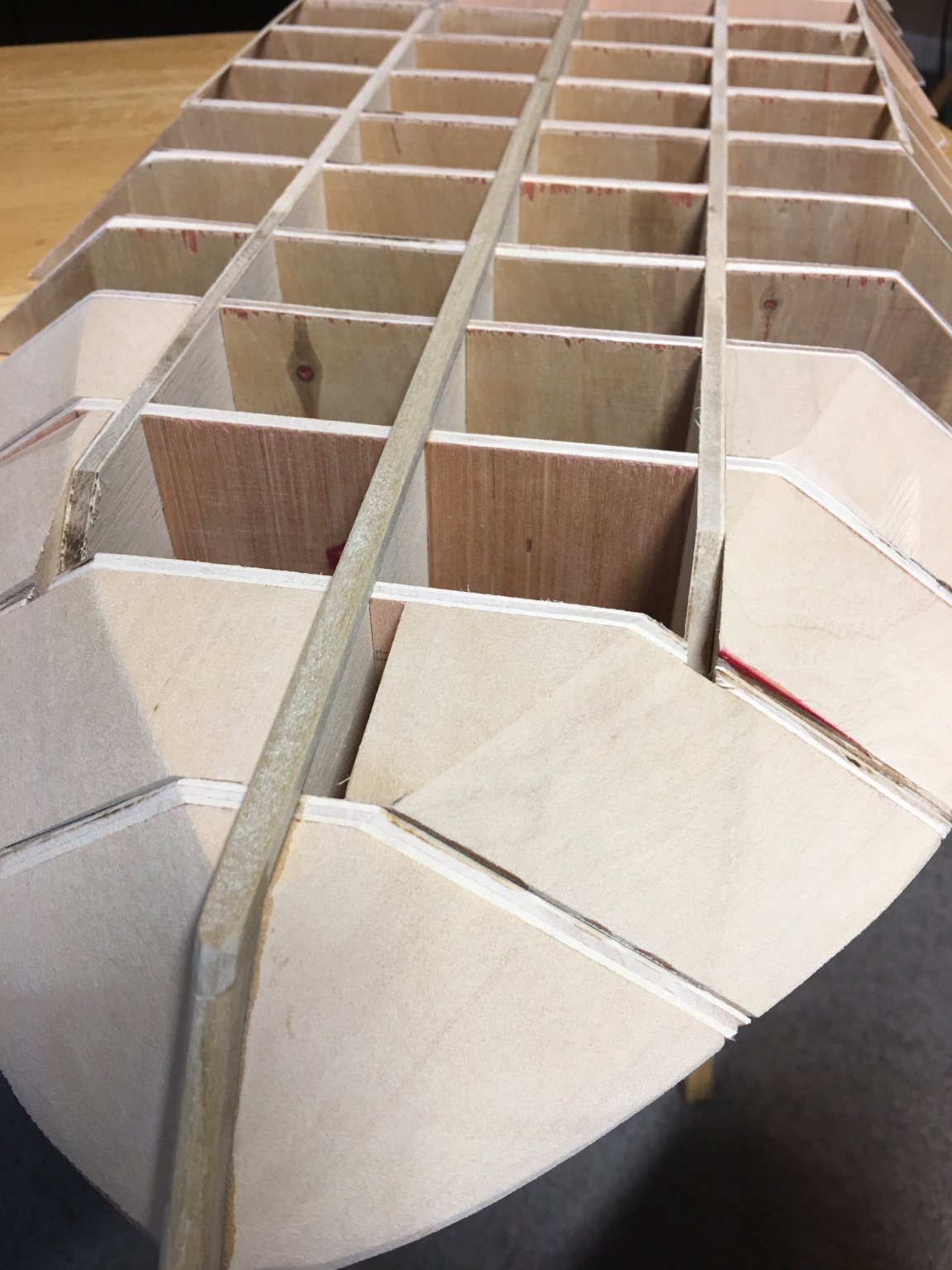
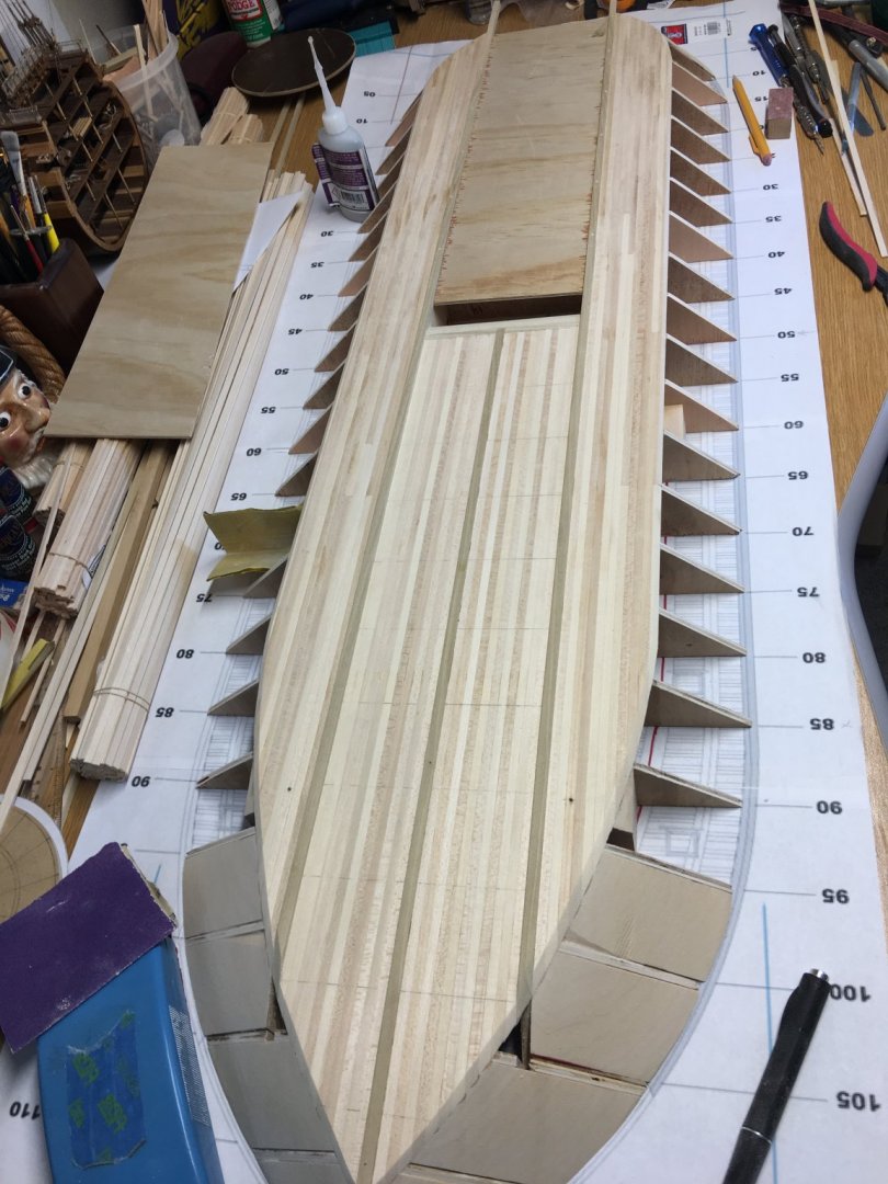
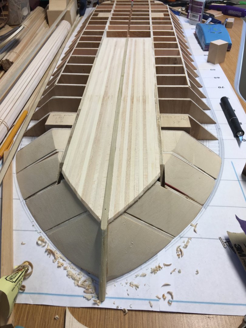
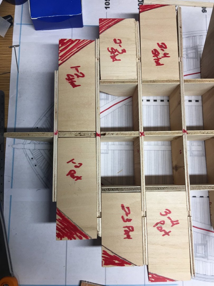
Hello Everyone, It's been a little hectic over here since my last update. With the warm weather we had several of our goats give birth within a few days of each other, so time has been split between nursing kids and my build. I did manage to make some progress on my Cairo though (along with a lot of sawdust) and her hull is finally starting to take shape. I cut out the filler blocks for the bow and stern sections and got them all temp installed into place. I then used my template to mark the hull outlines on top and bottom. This is where a lot of sawdust was generated. The filler blocks were cut down and glued into place. Then they were shaped to the contour of the hull with the sander. Next, I installed the center keel and stempost. Next, I started planking the hull bottom on both sides of the center keel between the port and starboard keels. I finished up with the center planking and then installed the port and starboard keels. I also installed the display mount blocks. Since this is a rather wide ship, I decided to go with four mount points to give it a better stance for stability. Not to mention that with all of this wood, this is going to be a fairly heavy model and I definitely don't want to risk any damage to it by scrimping on the display. Once I had started the center keel hull planking, I noticed that the port and starboard false keels had developed a slight curve to them beginning just past the end of the center keel. Rather than just trust the CA to hold everything in place, I decided to drill and install trenails along the false keel to add extra support. I also temp installed a piece of 1/8" plywood between the keels to keep them straight until the bottom hull planking was done. Just to be sure that everything stays straight. From here I will work on planking the rest of the hull bottom. As you can see from the above picture I have some of it in place on the starboard side. This week I will try to finish up on it and get it all sanded flush with the edge of the hull sides, then hopefully start planking the hull sides. Until the next update, thank you all for looking and for all of the likes. - Brian


- 739 replies
-
- 18
-
-
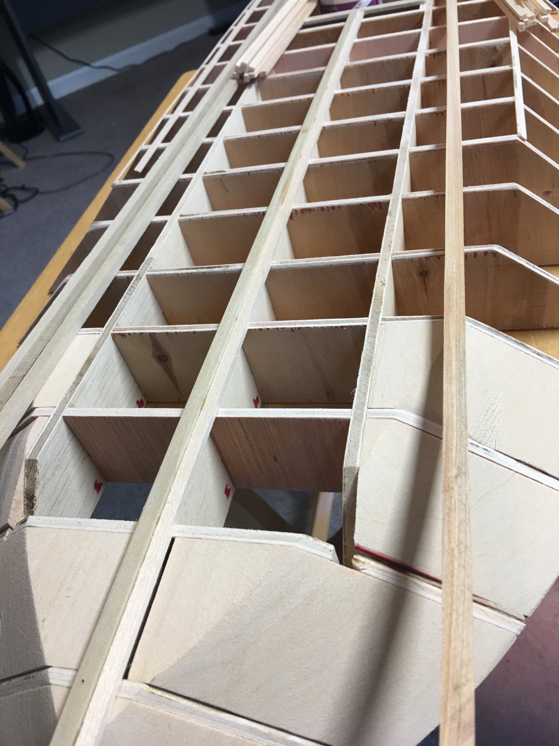
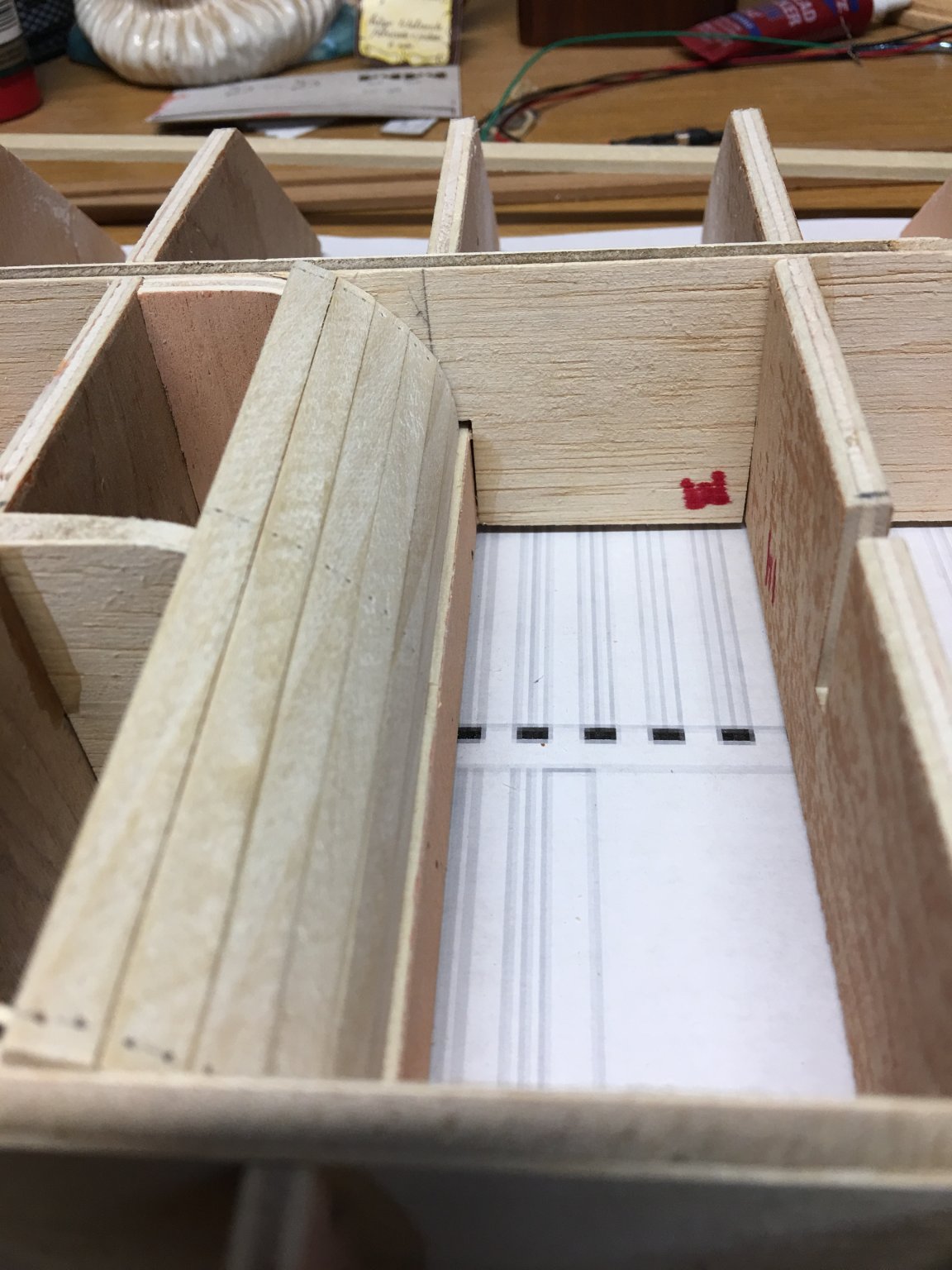
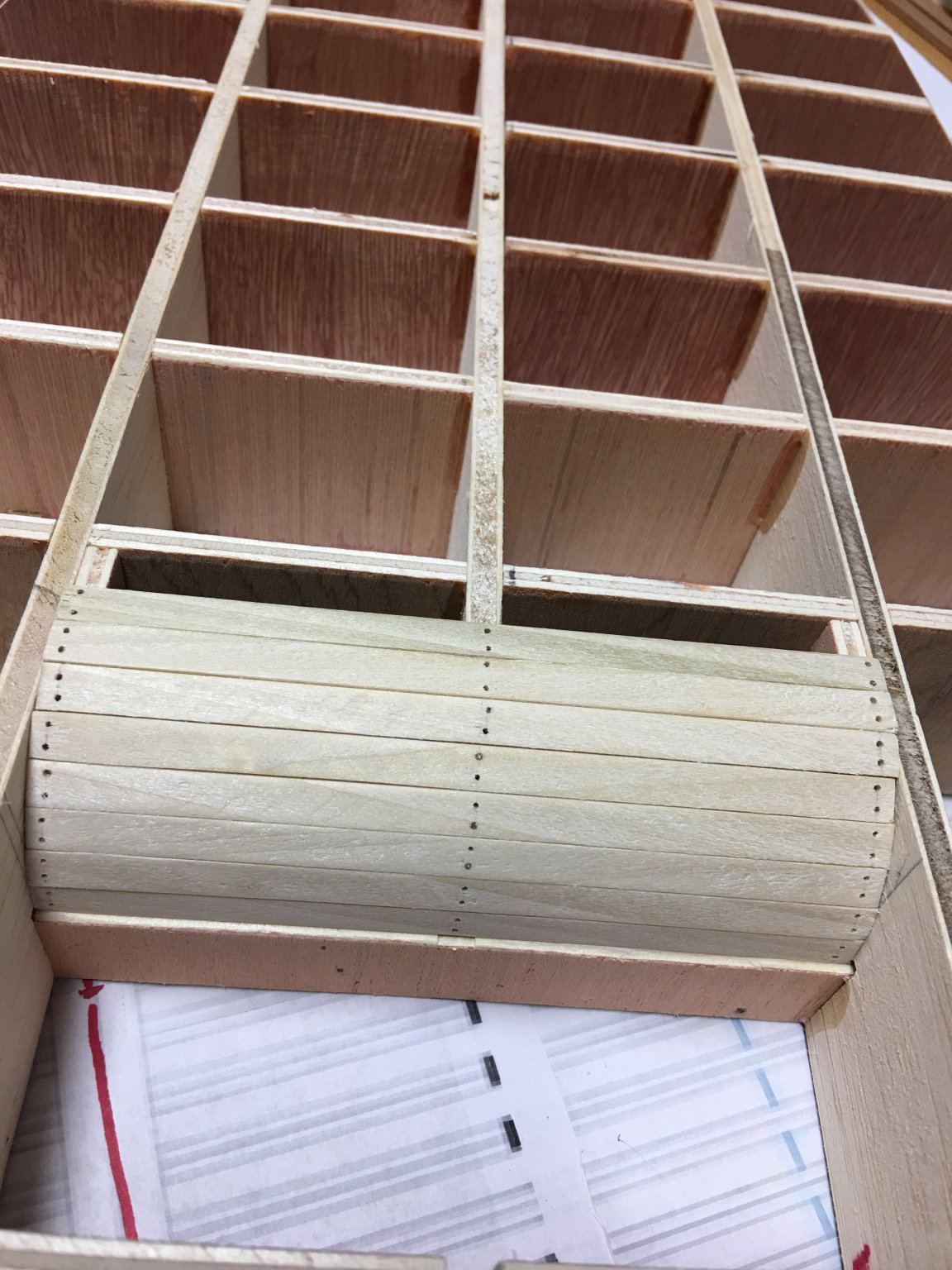
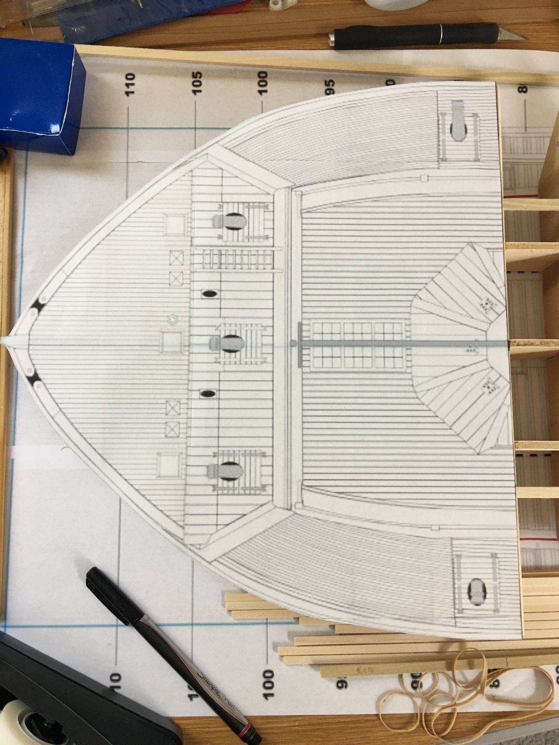
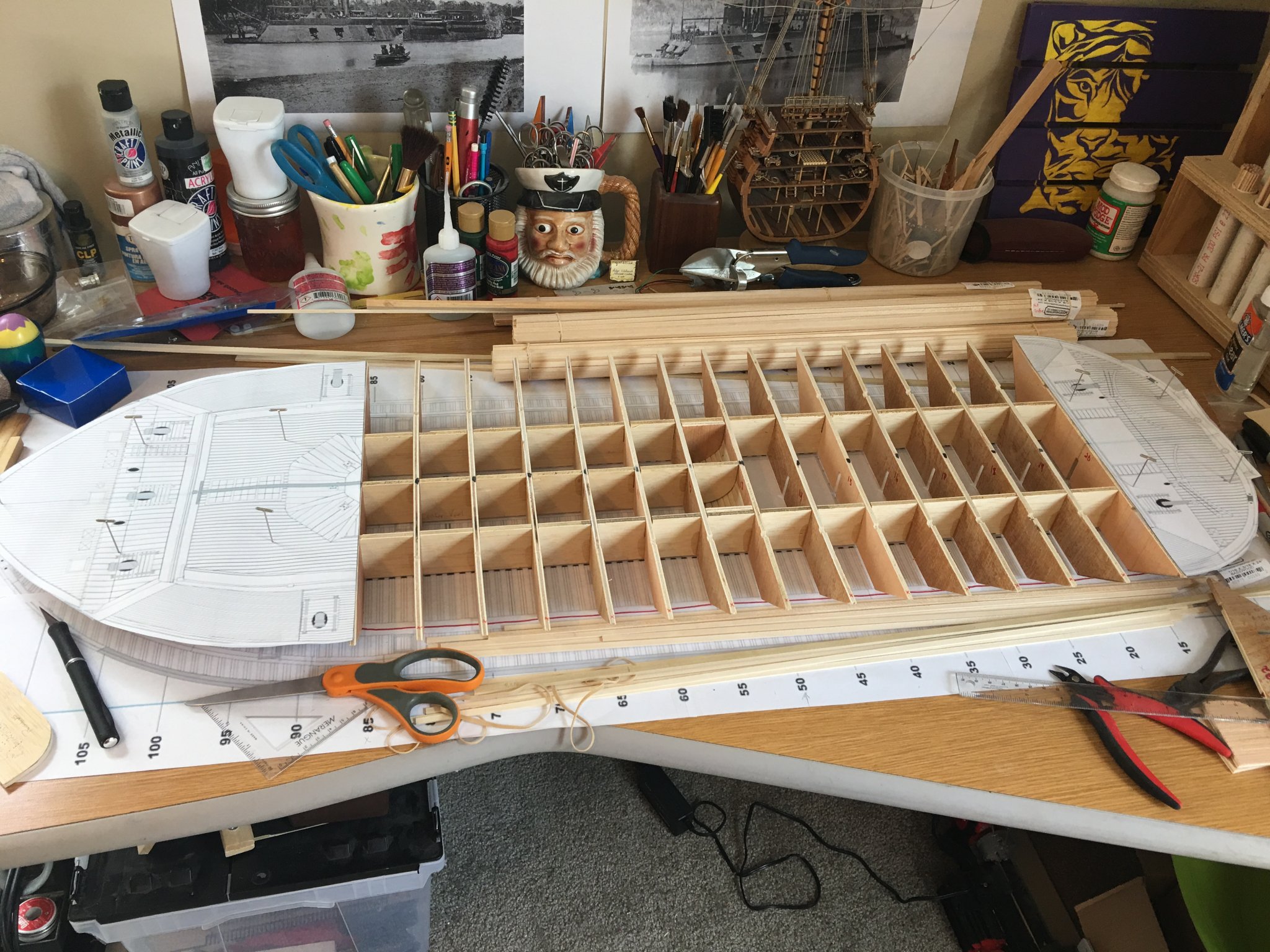
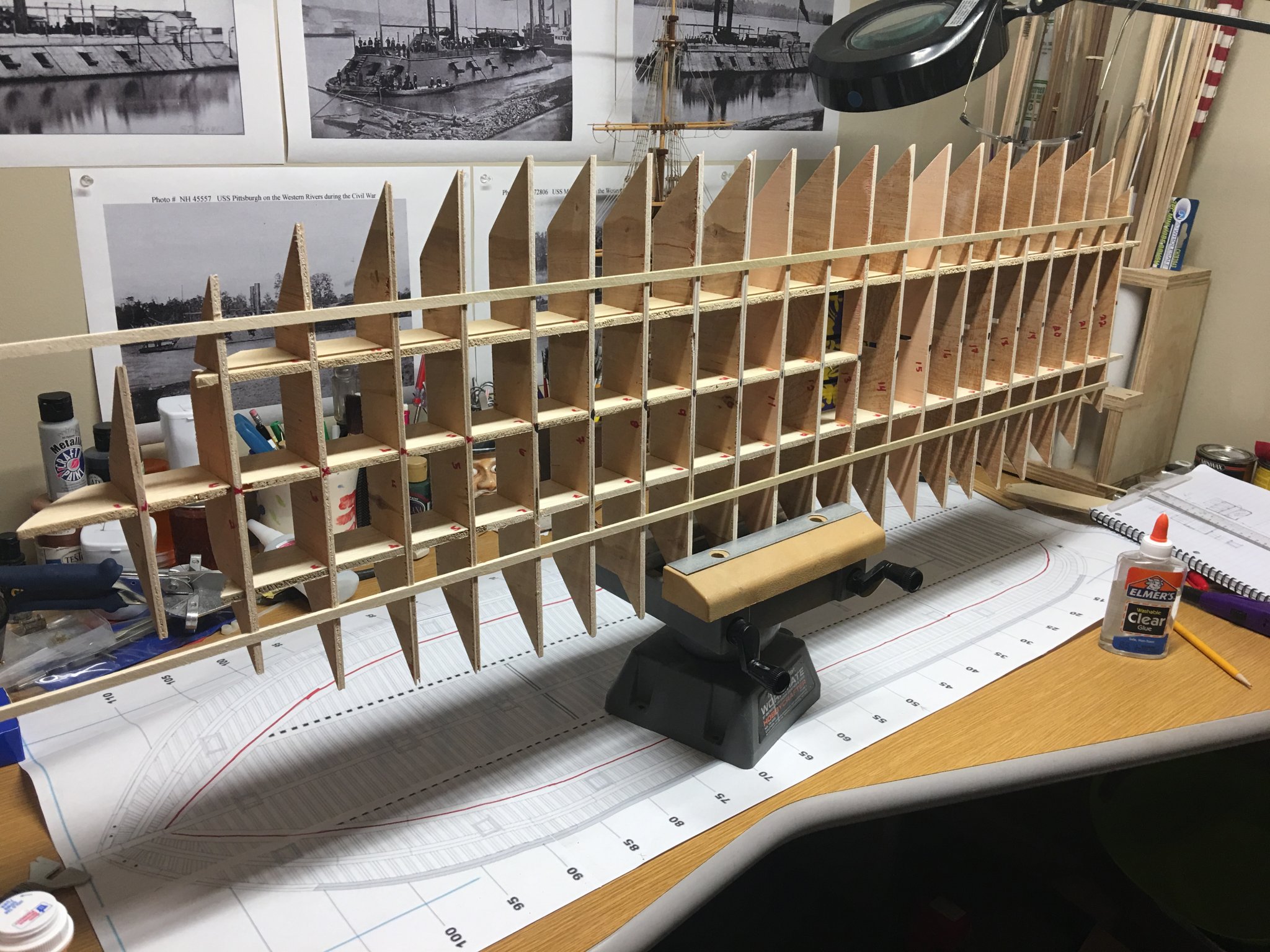
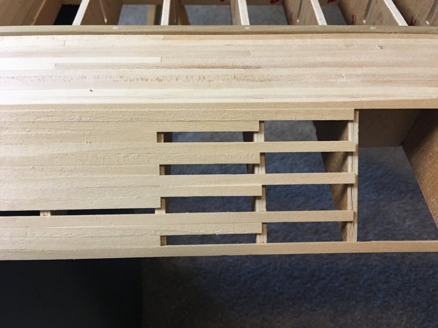
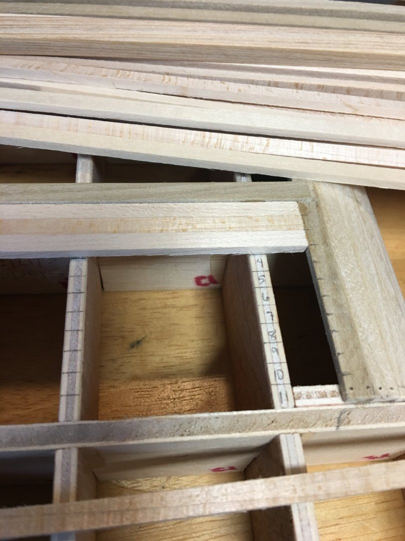
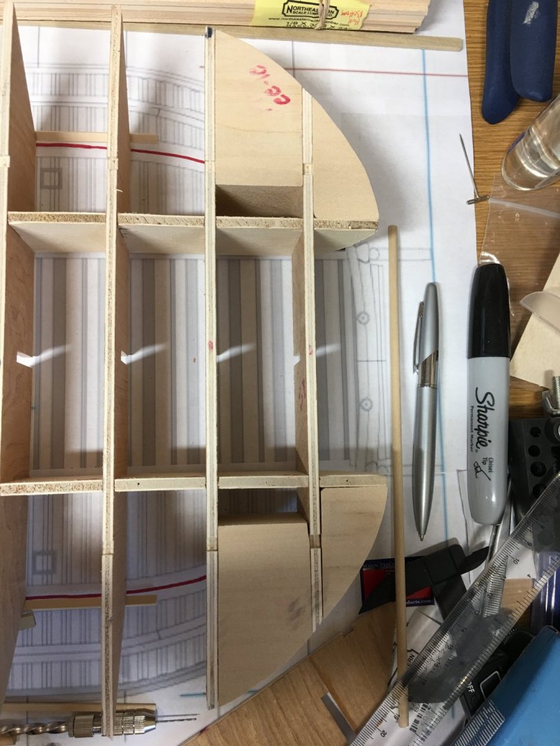
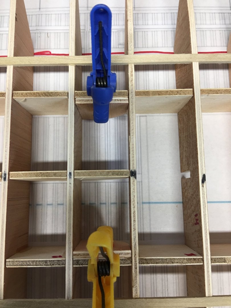
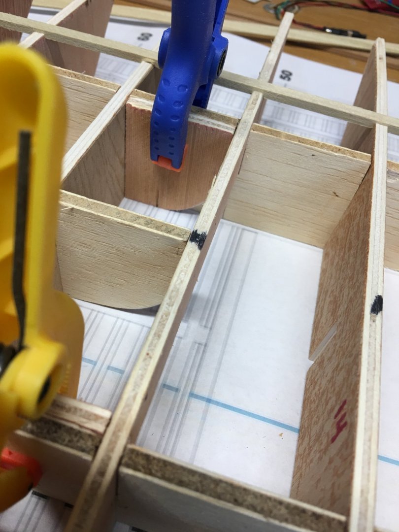
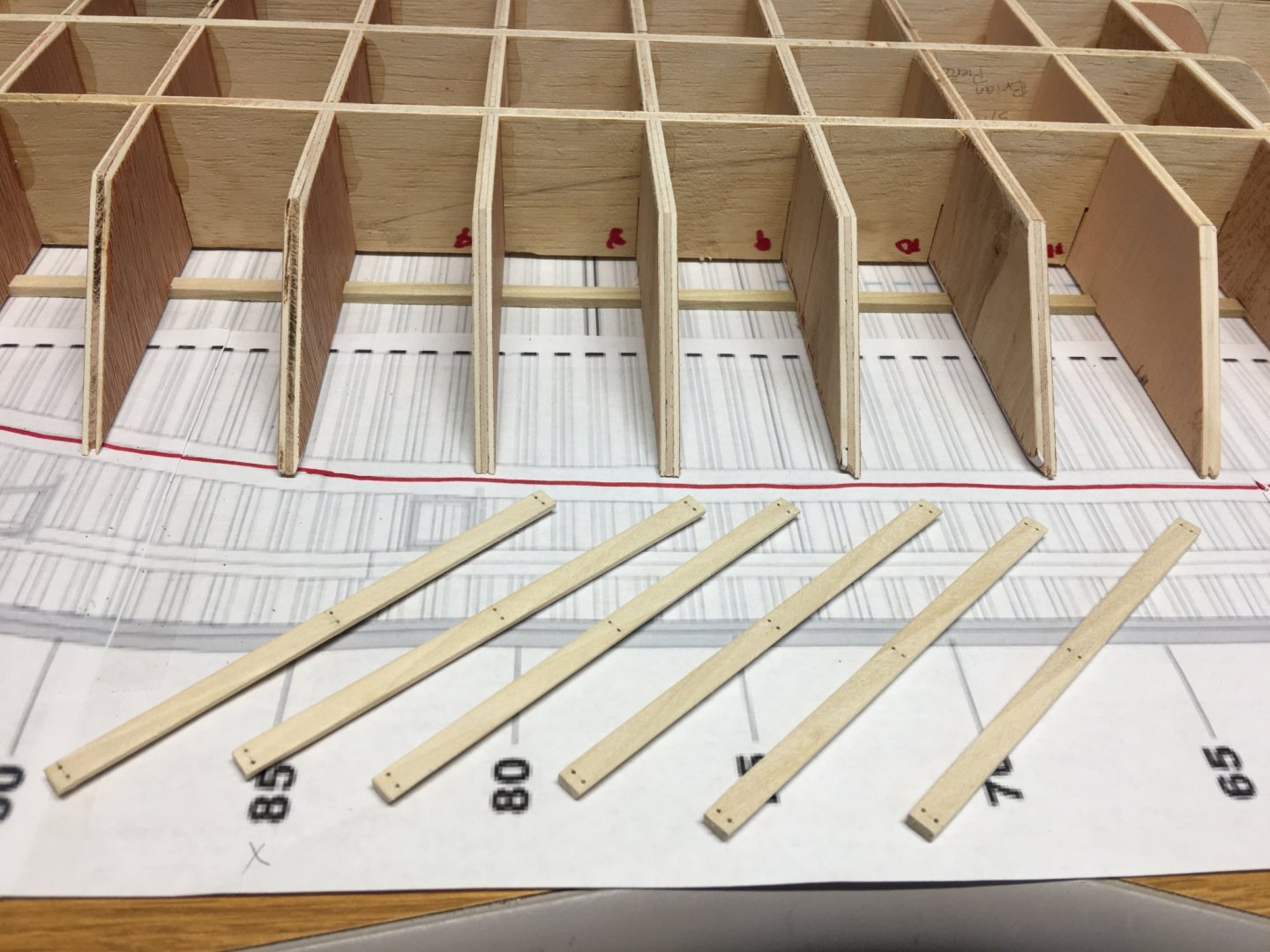
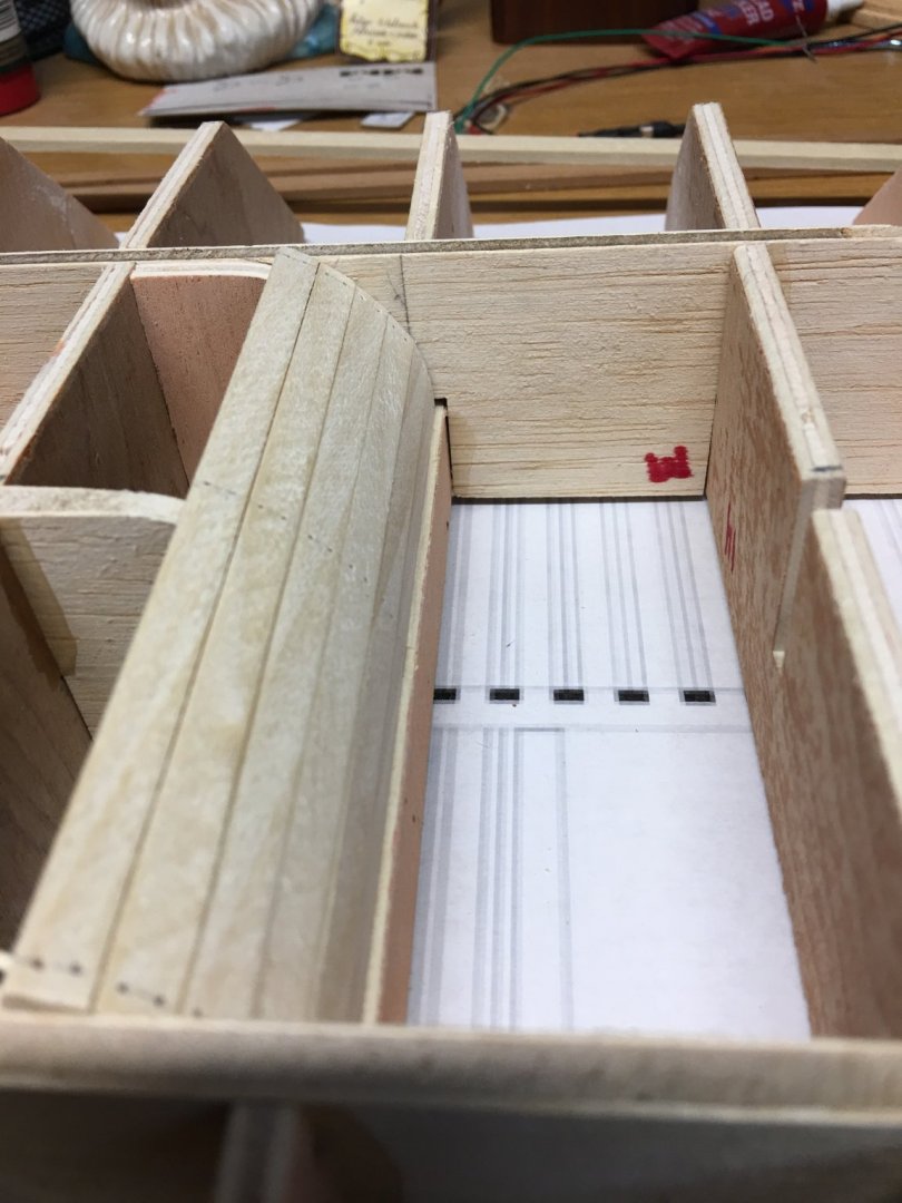
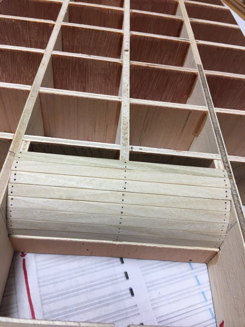
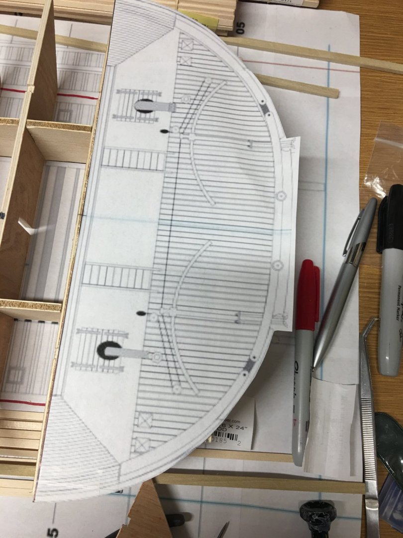
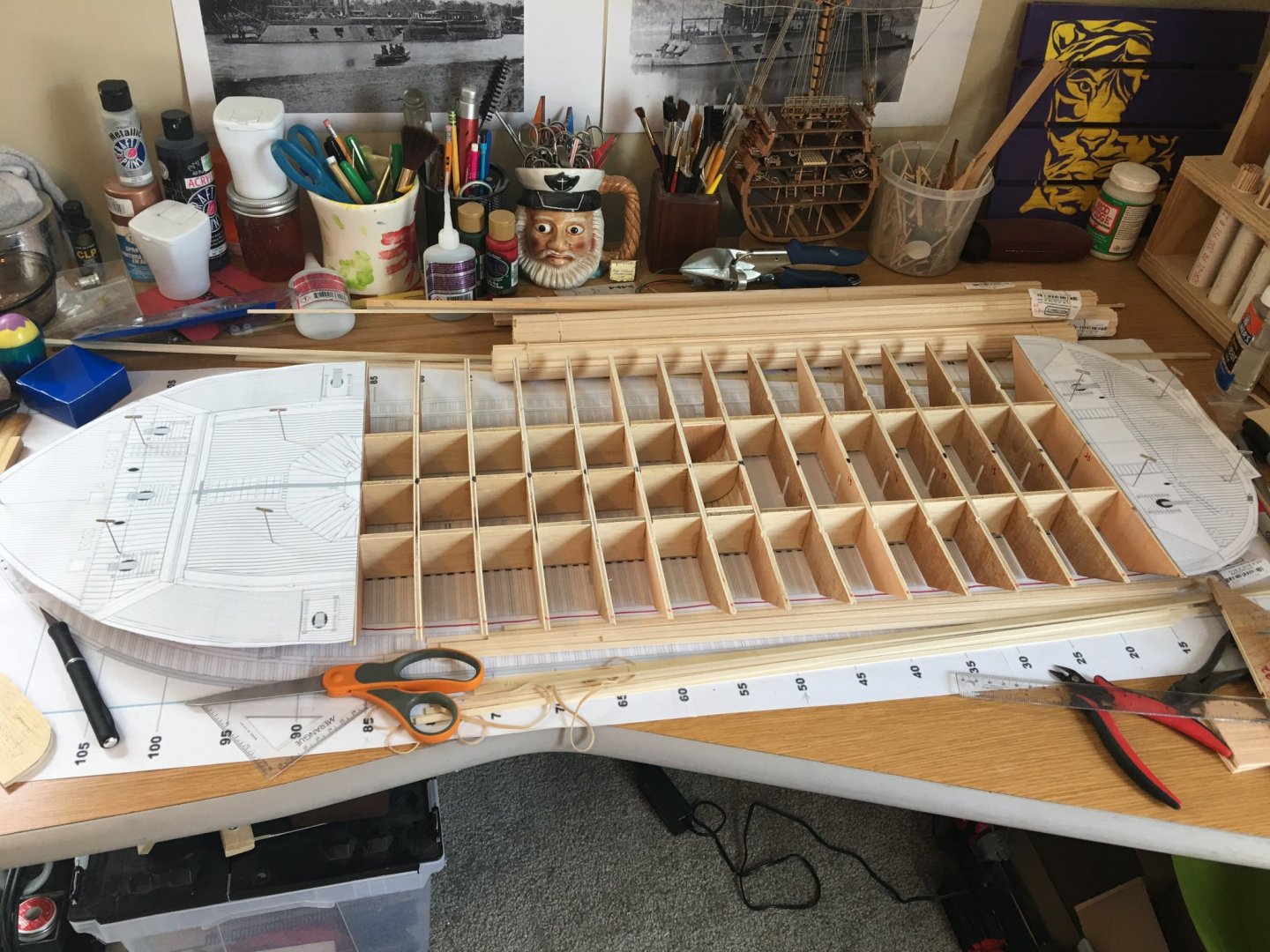
Hello again everyone, I managed to make a little progress over the week, but not a whole lot. My main hold up was waiting on my hull planking and other wood products to arrive. Fortunately, they arrived just before I sat down to type this up, so I am good to go. So here is what I was able to get done since last time. All bulkheads were squared up and glued in place. Then I cut out the pieces that will form the back side of the center hull, just in front of the paddle wheel. Not sure of what you would call this section, but it is where the rear pontoons begin. These will provide a mounting brace for the planking that curves up from the bottom of the hull. Planking this rounded section of the hull. I had to give each of these planks a slight taper on the insides so they would fit together nice and snug. All the planks in place. I see now that I may need to up my magnification on my glasses. Some of my nail holes aren't all in line with each other. Thankfully this will be on the bottom and not seen. Next I printed out the Hurricane Deck plans and pinned them in place to use as a guide to help true up all of the bulkheads and to make sure they are all the correct width. From here I will get the bulkheads sized to the template and start putting in my filler blocks and shaping the hull. Things should move along a little better now that I have some material to work with. That's all for now. Thank you all for looking and for all the likes. - Brian


- 739 replies
-
- 18
-
-
Eric, All I can say is absolutely beautiful. It's been a pleasure watching the progression of this build along the way. Really looking forward to seeing the final photos, especially the ones along the Missouri River. Those should really prove to be stunning. You've also got my curiosity piqued on the reveal of your next build. Are you planning a display case to go along with it? I need to get my rear in gear on my Chaperon case, otherwise I may have to sacrifice some of my build time dusting it. -Brian
- 599 replies
-
- 3
-
-
- sidewheeler
- arabia
- (and 4 more)
-
vaddoc, I’d love to go bigger, unfortunately my budget and my space won’t allow it. Not to mention the Admiral would have me walk the plank. 😃 -Brian