HOLIDAY DONATION DRIVE - SUPPORT MSW - DO YOUR PART TO KEEP THIS GREAT FORUM GOING! (Only 20 donations so far - C'mon guys!)
×


mbp521
-
Posts
1,002 -
Joined
-
Last visited
Content Type
Profiles
Forums
Gallery
Events
Everything posted by mbp521
-
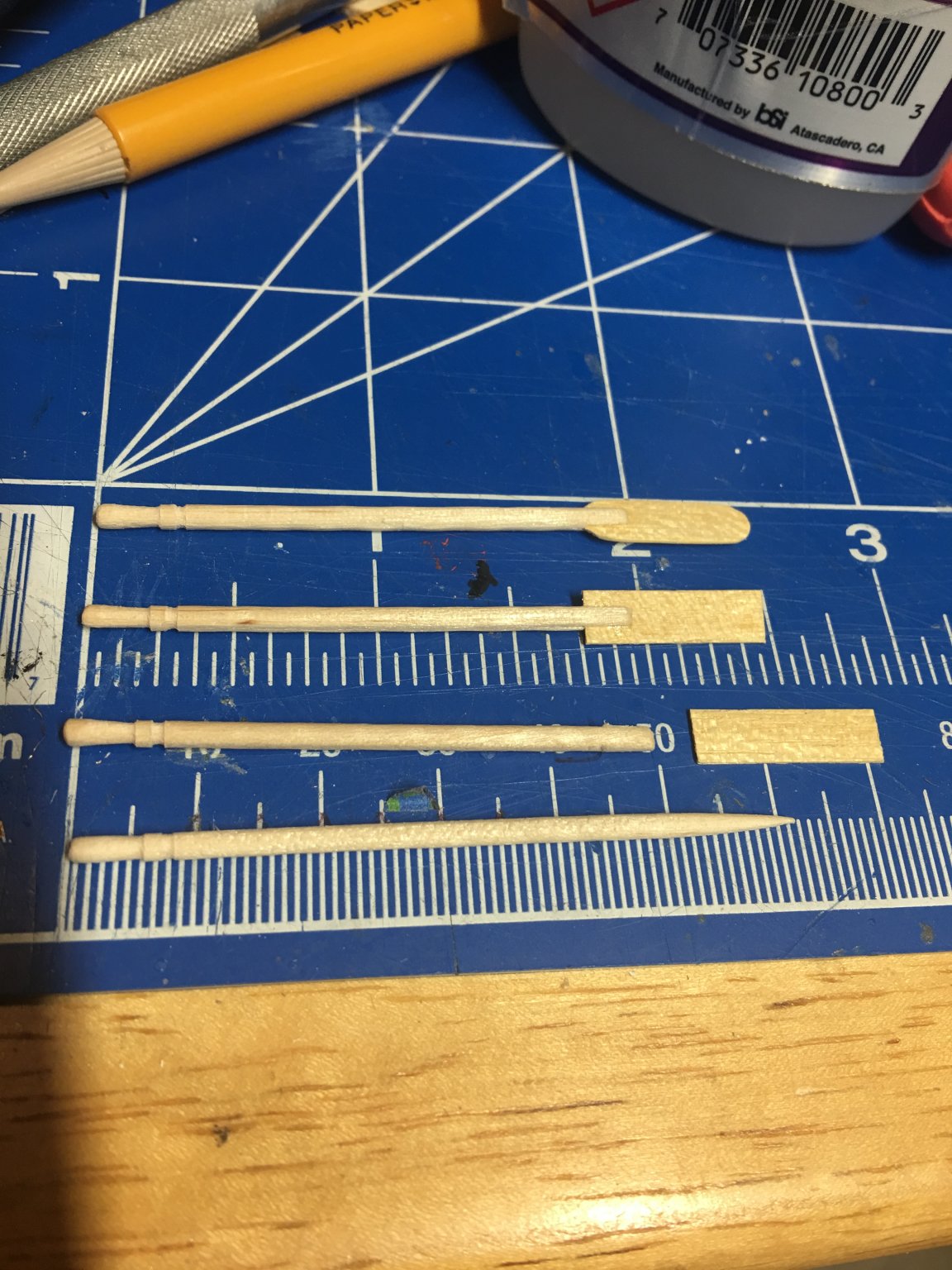
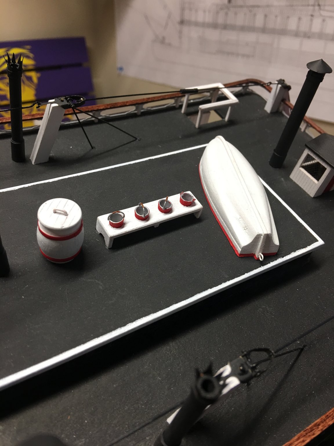
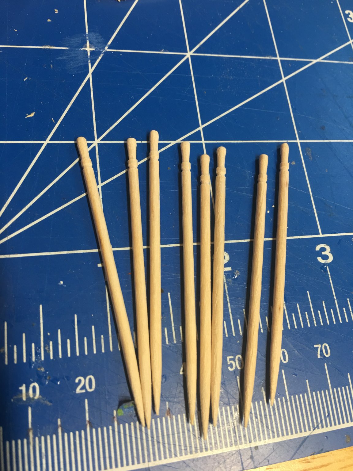
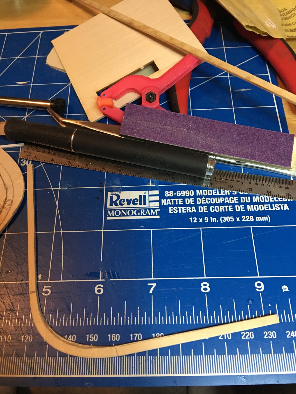
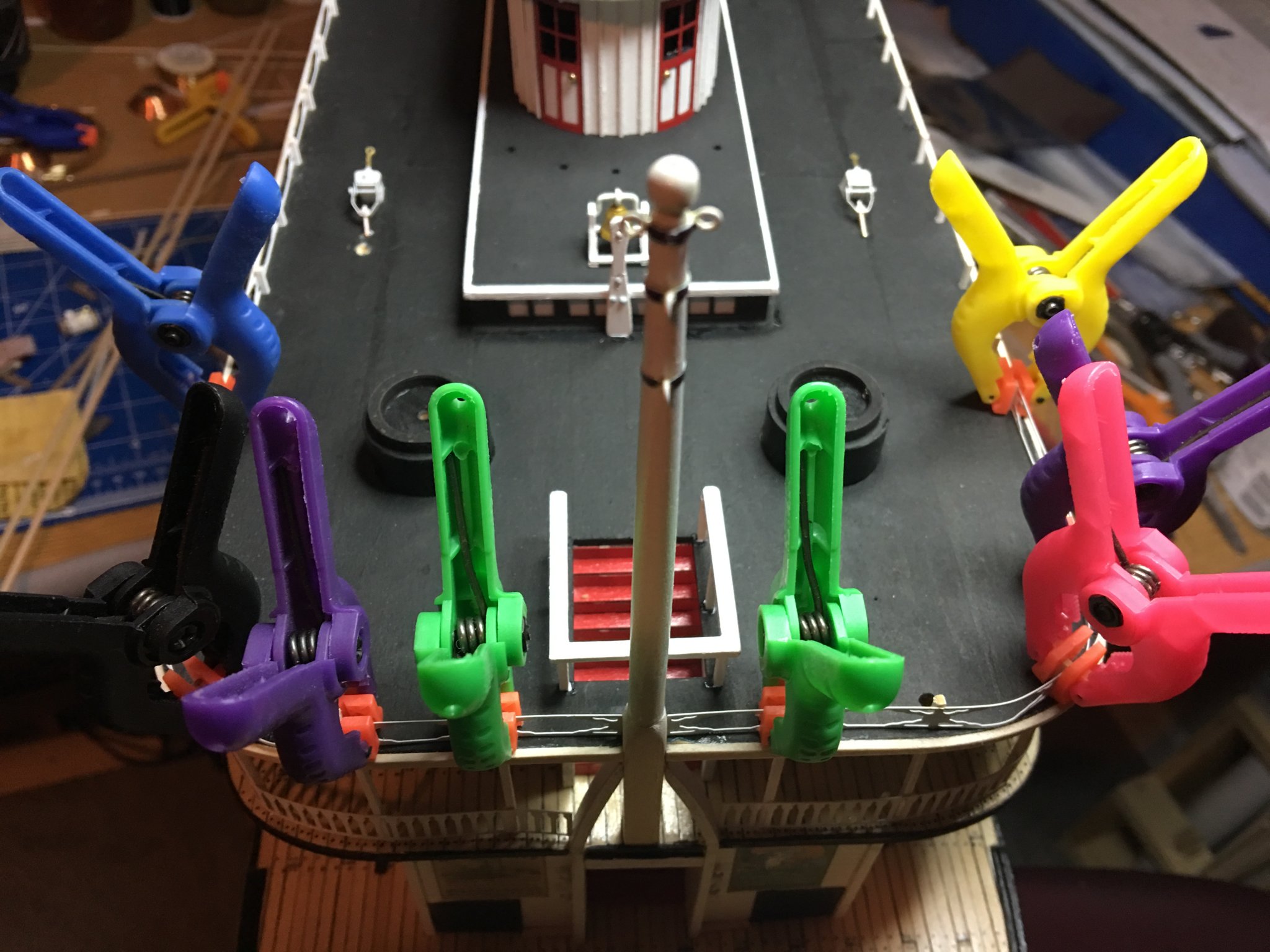
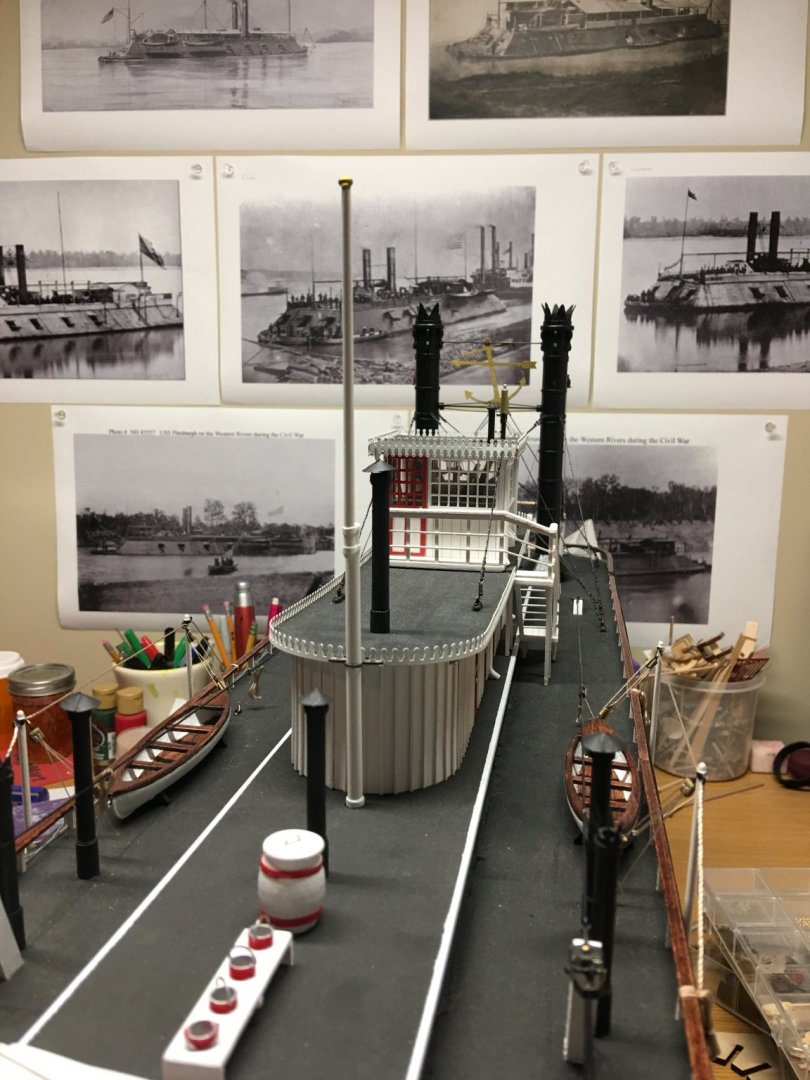
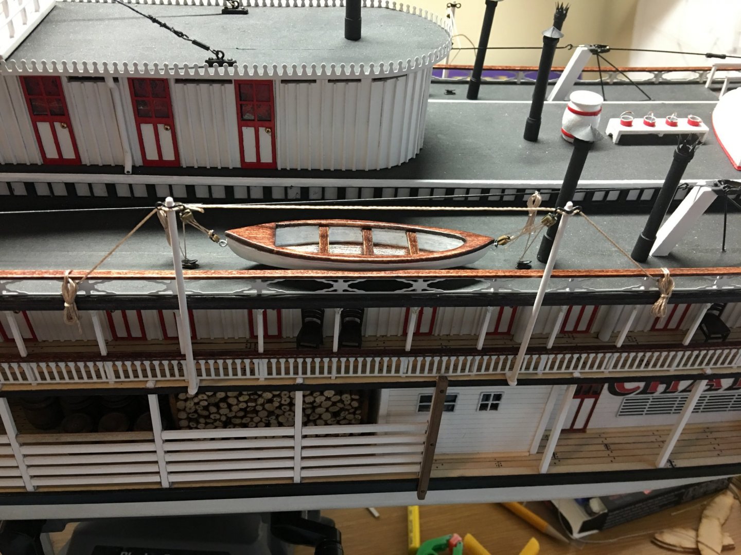
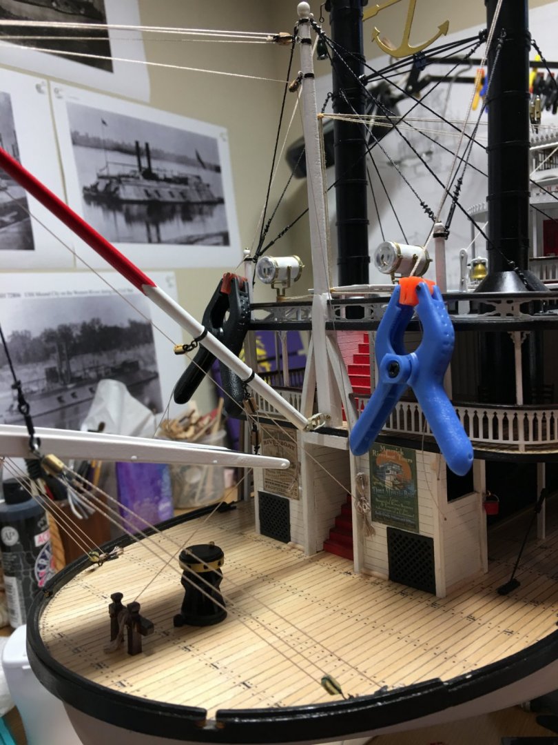
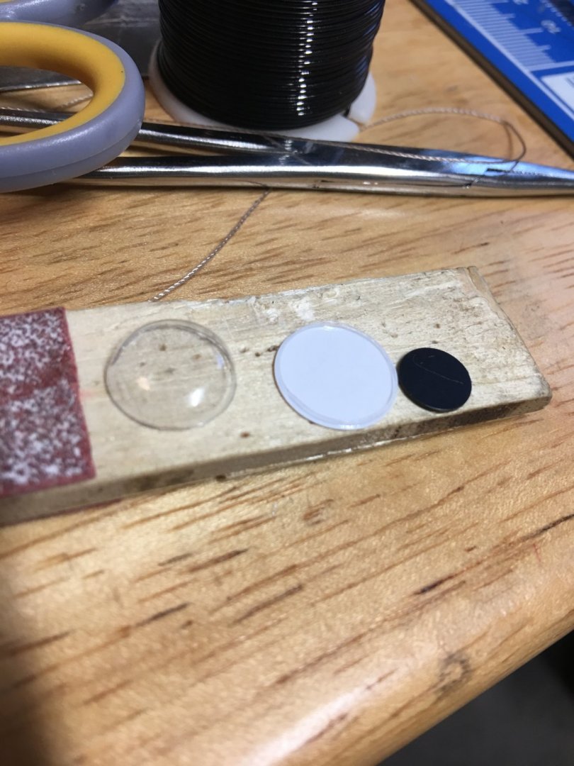
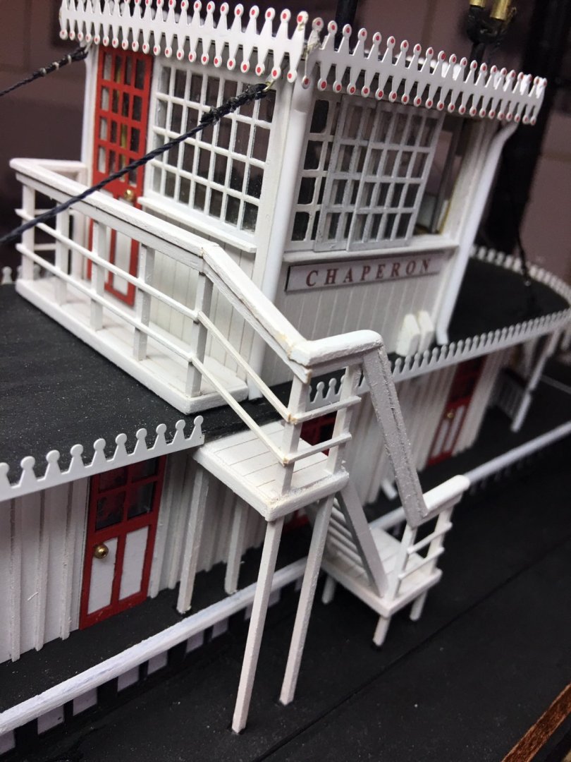
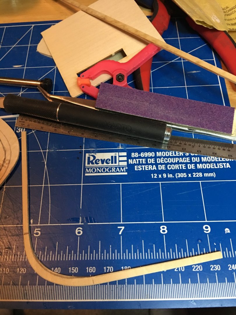
 Hello all, Time for another update. As the weather starts to get nicer, outdoor projects are starting cut into build time. I am rapidly approaching the finish line on this project which in a way is a good thing since I have so many projects that need tending to. I managed to complete a few things this week as well as a little touch up paint in some areas. Lifeboats were set in place and rigged. I put together this simple little jig to make the rope coils. Really easy and can knock them out super quick. Just wrapped the string around the thumbtacks, looped the string around itself through the groove and tie it off. A little dab of CA on the knot and all is good. I started making oars for the lifeboats and work boat, but once I completed a couple of them I realize that they were not quite to scale. I should have paid a little more attention to these while was making them. Oh well, back to the drawing board on these. I completed the work boat. I wasn't real happy with the way the insides looked so I decided to go ahead and place it upside down and just show the bottom. I have seen several pictures of these stowed this way on the decks. Final rigging on the navigation lights was completed as well. Lastly, I completed the flag pole and mounted it. I am trying to decide which ensign to place on it. three different versions would have flown on Chaperon while she carried this name, the 45, 46 & 48 star versions.. Unfortunately the kit doesn't come equipped with one, so I am going to have to fabricate one. I'd like to try and make them in some other fashion other than printing them on paper. so any advice on other ways to make them is always welcome. Just a few more minor details left and she should be complete. I need to make up the steps for the Hurricane Deck, rig the flagpole and one other addition that I will hold off on disclosing until I get it completed. It's a little detail that I ran across on researching old pictures of the boat that I think will be a nice touch. Something I haven't seen on a steamboat build yet. So bear with me, I think you'll be pleasantly surprised. As always, thank you for the likes, kind comments and looking. -Brian


- 133 replies
-
- 6
-

-
- chaperon
- model shipways
- (and 2 more)
-
Eric, Great job on the railing. Looks like the jig worked perfectly. I can see where you could get a little nervous when working around it. I had the same dilemma with my work boats as well. I finally ended up using the britannia ones that came with the kit to place in the cradles on the sides, only I doctored them up a little. I also put together a spare kit that I had purchased from Model Expo some time ago. At Rogers direction, I looked up the Ohio River yawl boats and found several versions that closely resembled the kit that I had on hand. The only major difference was the bottom wasn't quite flat, but I think it looks just fine. I haven't updated my build log yet with pictures of it but I should have it done tonight or tomorrow. This is the kit that I used. https://modelexpo-online.com/SHIPS-BOAT-KIT--2-58--LASER-CUT-WITH-STRIP-PLANKS_p_3427.html -Brian
- 599 replies
-
- 4
-
-
- sidewheeler
- arabia
- (and 4 more)
-
Eric, Beautiful job on the railings. I myself am spoiled to the PE ones my kit came with. This is definitely a tricky and time consuming part of the build doing it all from scratch. As for moving your Arabia around, please handle with care. We don't want your beautiful build meeting the same fate as the real Arabia. -Brian
- 599 replies
-
- 2
-
-
- sidewheeler
- arabia
- (and 4 more)
-
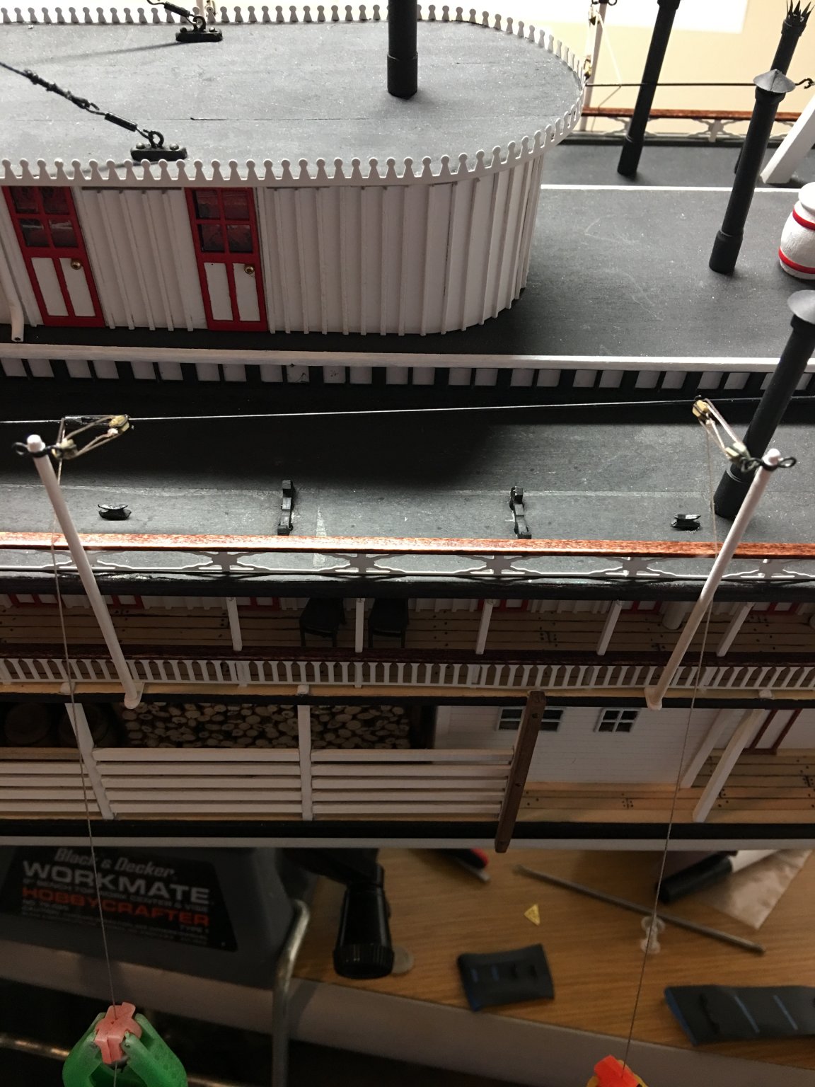
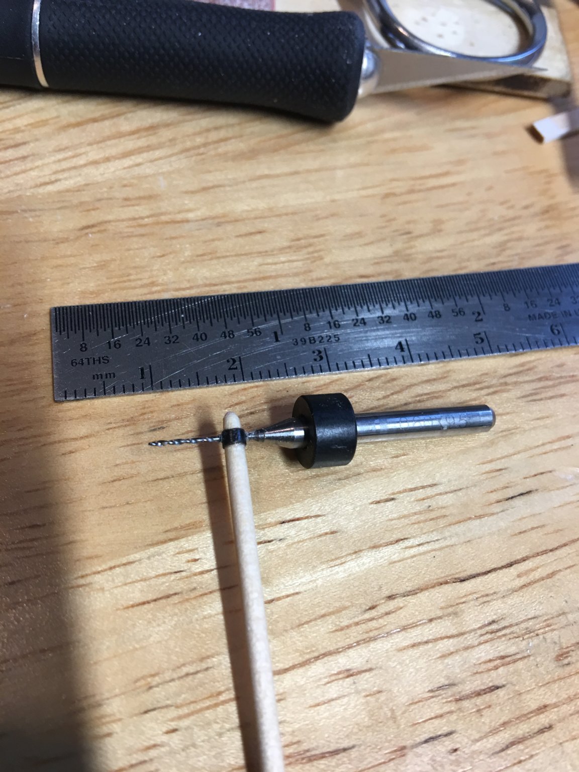
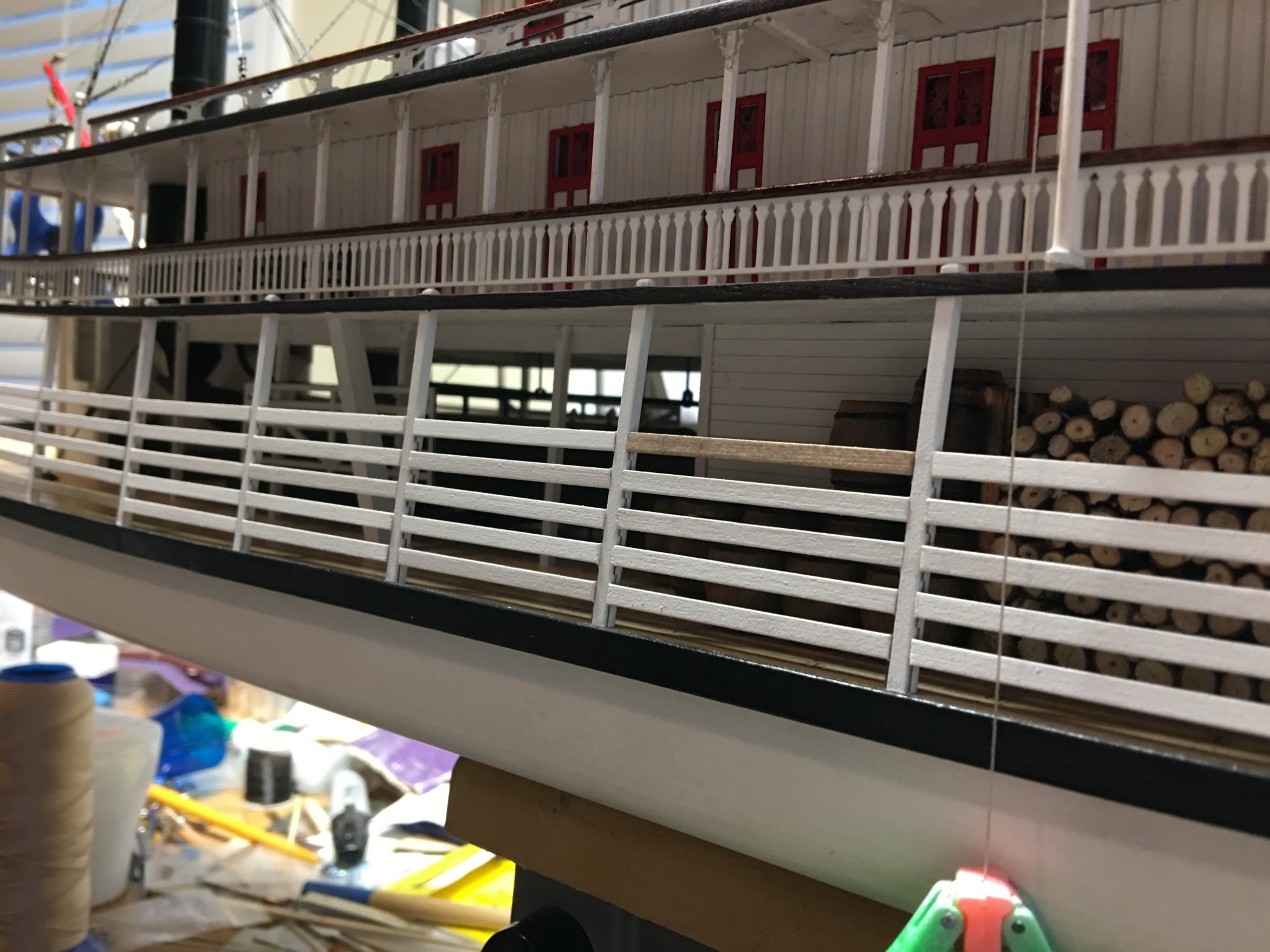
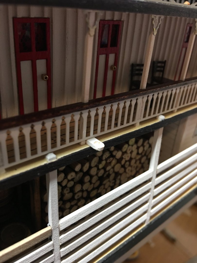
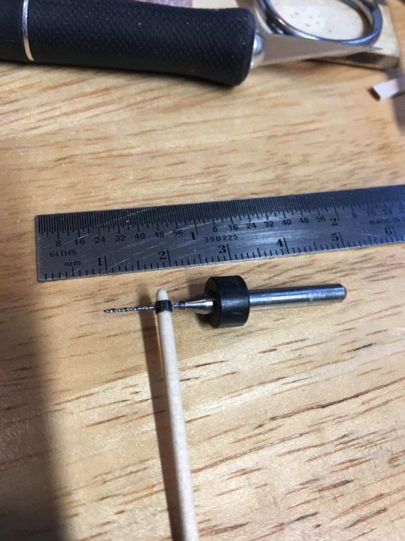
Good evening everyone, I hope this find you all in good health. This week there is not much of an update, with all that is going on in the world and the COVID-19 virus affecting every corner of the world my primary focus this week has been setting the admiral and I up with temporary offices in the house since we have both been directed to work from home until further notice. What was accomplished this week was the completion of the forward rigging on the landing stage, the installation of the bull rails, navigation lights and the lifeboat booms. Finished rigging of the landing stage. Next was the installation of the bull rails. Another tedious task, although nothing compared to the placing all the battens on the Boiler and Texas decks. In order to access the battery for the LED's, I made a removable section so that I can remove the shipping crate to connect and replace the battery. As a little touch of realism, I left a couple of the bull rails unpainted. I was going for the effect of the crew having to replace a few broken ones and not quite having the time to get them painted up. I used a little bit of graphite from a pencil lead shaved off on some fine sandpaper. Just rubbed on the bare wood with my finger to give them a slightly weathered look. I completed the construction of the lifeboat booms and their brackets. as well as the cleats and boat rests. I found these inexpensive micro drill bits on Amazon. They are extremely handy when drilling the small holes and cleaning out the sheath holes in the blocks. They are made for circuit boards but I found them more convenient than using a pin vise. Boom sockets in place. Booms, cleats and boat rests in place and rigging ready to receive the lifeboats. Lastly, the navigation lights have been painted up and partially installed. I wanted to run these with miniature LED's but I couldn't figure out a way to get the wiring ran where it wouldn't be visible, so I just painted them. And here is an overall picture of where she sits now. Not too much more to go. This week I will try to finish up on the lifeboats and get them installed. I also had an extra lifeboat that I had purchased from Model Expo several years ago that will make a nice work boat. I think I will assemble that one and add it to the top. Thanks for all the likes and for looking. -Brian


- 133 replies
-
- 9
-
-
- chaperon
- model shipways
- (and 2 more)
-
Not to worry, I wasn’t offended by it. This Corona thing has lots of people stressing. In hindsight I now see that there were several areas lacking in the AL kit. I had seen the assembled kit 20 or so years ago in a hobby shop and thought it was really neat looking. At the time the $100 price tag was a bit out of my budget and raising three kids didn’t allow time for the hobby, so when it came time that I could afford it (not to mention I picked it up on sale about three years ago) I figured why not give it a shot. I had built the AL Endeavor and was working on the AL Constellation (which is a kit that is also lacking in accuracy) so why not go for it. You are correct, there does need to be more options available for historically accurate entry level steamboat kits (and Ironclads). As for Model Expo, I have been buying from them since the early 80’s. I hope this crisis ends soon so they can get back to it stronger than ever. Too many of their kits on my wish list I want to build. Fortunately for them they have an Amazon store to help them out during the shutdown (while supplies last). -Brian
- 133 replies
-
- 2
-
-
- chaperon
- model shipways
- (and 2 more)
-
Eric, Ooof. I was one of those who built the KotM. While it is definitely not historically accurate or representative of an actual steamboat, I will have to give it a little credit, it did spark my interest in the steamboat era. While it it is a lower end of the model scale and has its issues (nothing against AL), it did make a nice looking model. I have mine sitting on a cabinet in my office at work and I get compliments on it all the time. Of course this is from those that don’t know better. Lol All in all, it was a fun build, but nothing in comparison to the quality and fun of the MS Chaperon. Totally different league. Speaking of Model Shipways, I received an email from Model Expo that they were closing their doors due to the COVID-19 virus. Truly heartbreaking. Hopefully this will all blow over soon and I hope everyone stays healthy. -Brian
- 133 replies
-
- 2
-
-
- chaperon
- model shipways
- (and 2 more)
-
Tom, thank you you for the kind words. For all the top decking I used silkspan and Modpodge for the tarpaper look. I cut scale strips of silkspan, applied a coat of Modpodge then laid the silkspan over it. Each strip is slightly overlapped to give it the tarpaper look. Once this was all dry, I painted it all with a coat of flat acrylic black paint. Where the silkspan strips overlap, I went a little over the lines to give the effect of the tar seeping through the joints. Pretty simple really. While I like this method of “tarpapering” the roof, the credit goes to Kurt Van Dahm. It was his article on constructing the Chaperon where I got the idea. There is is also a fantastic scratch build of the Arabia by Cathead where he uses masking tape and black pastel for the tarpaper look. I’m considering trying this method on a future build as a comparison. I hope this this information was useful. -Brian
- 133 replies
-
- 2
-
-
- chaperon
- model shipways
- (and 2 more)
-
Eric, Funny you should say that, my first thought was "Herbie the Love Bug" a Disney movie. Yves, I sure hope it does. This is a truly fantastic model, and it has been a pleasure to build. More builders should give it a go. -Brian
- 133 replies
-
- 3
-
-
- chaperon
- model shipways
- (and 2 more)
-
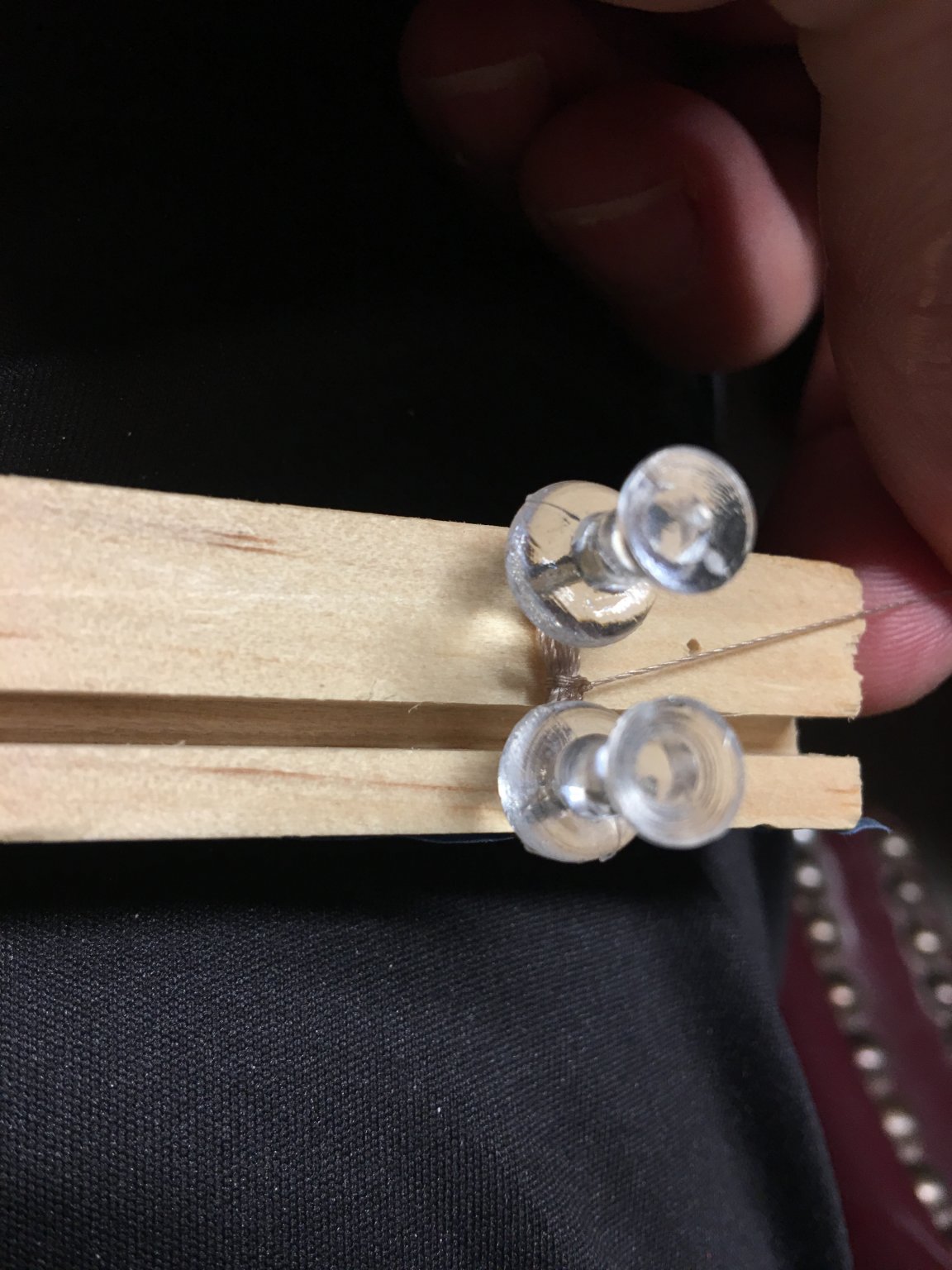
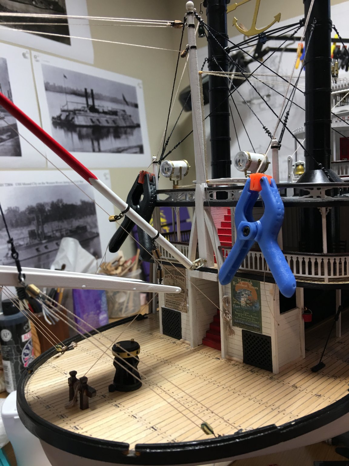
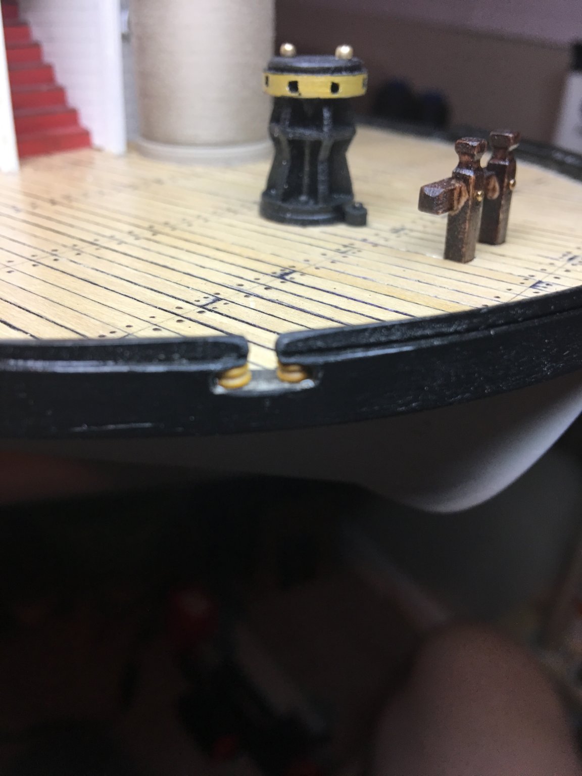
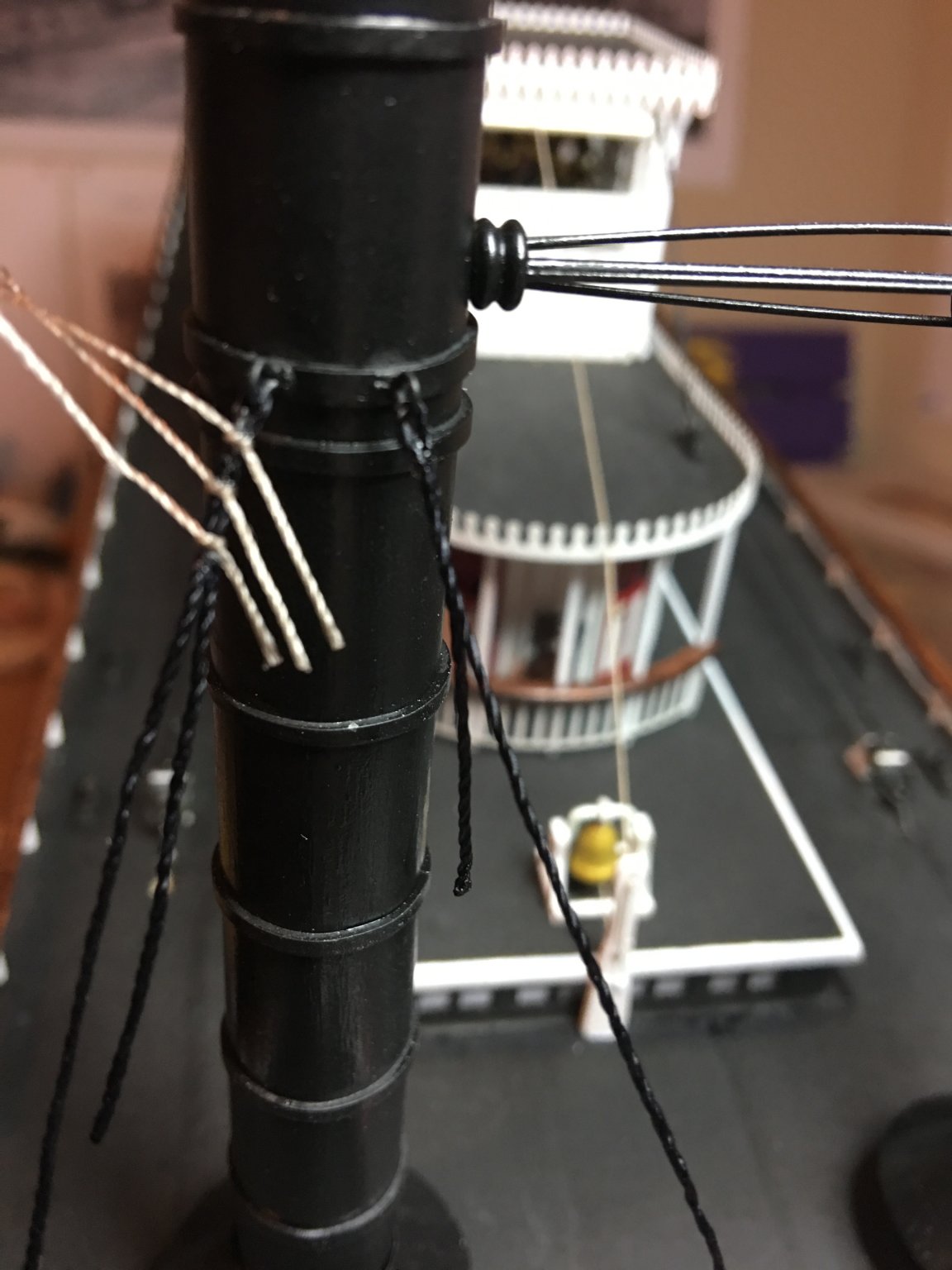
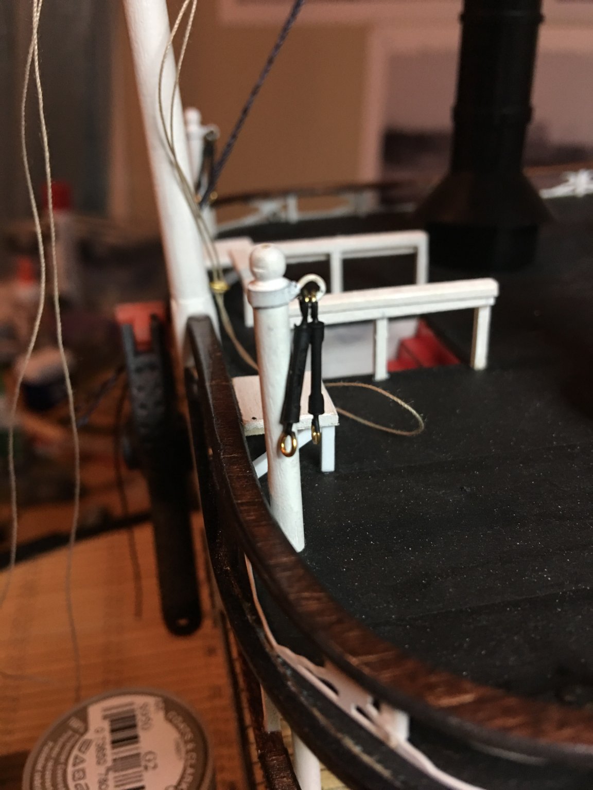
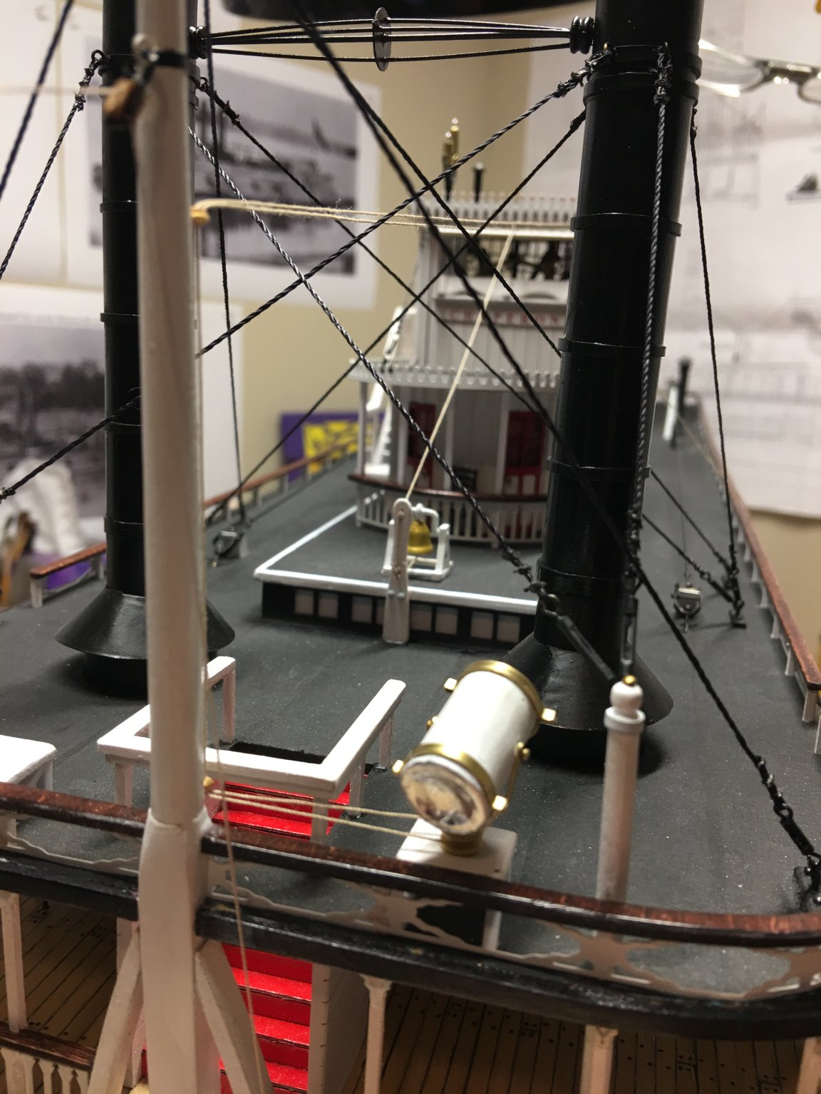
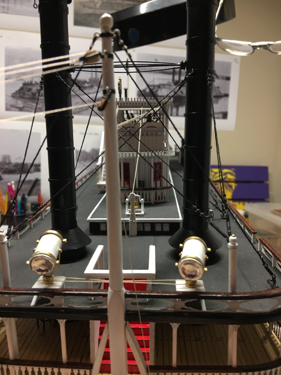
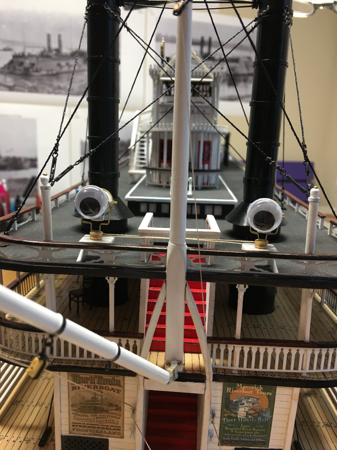
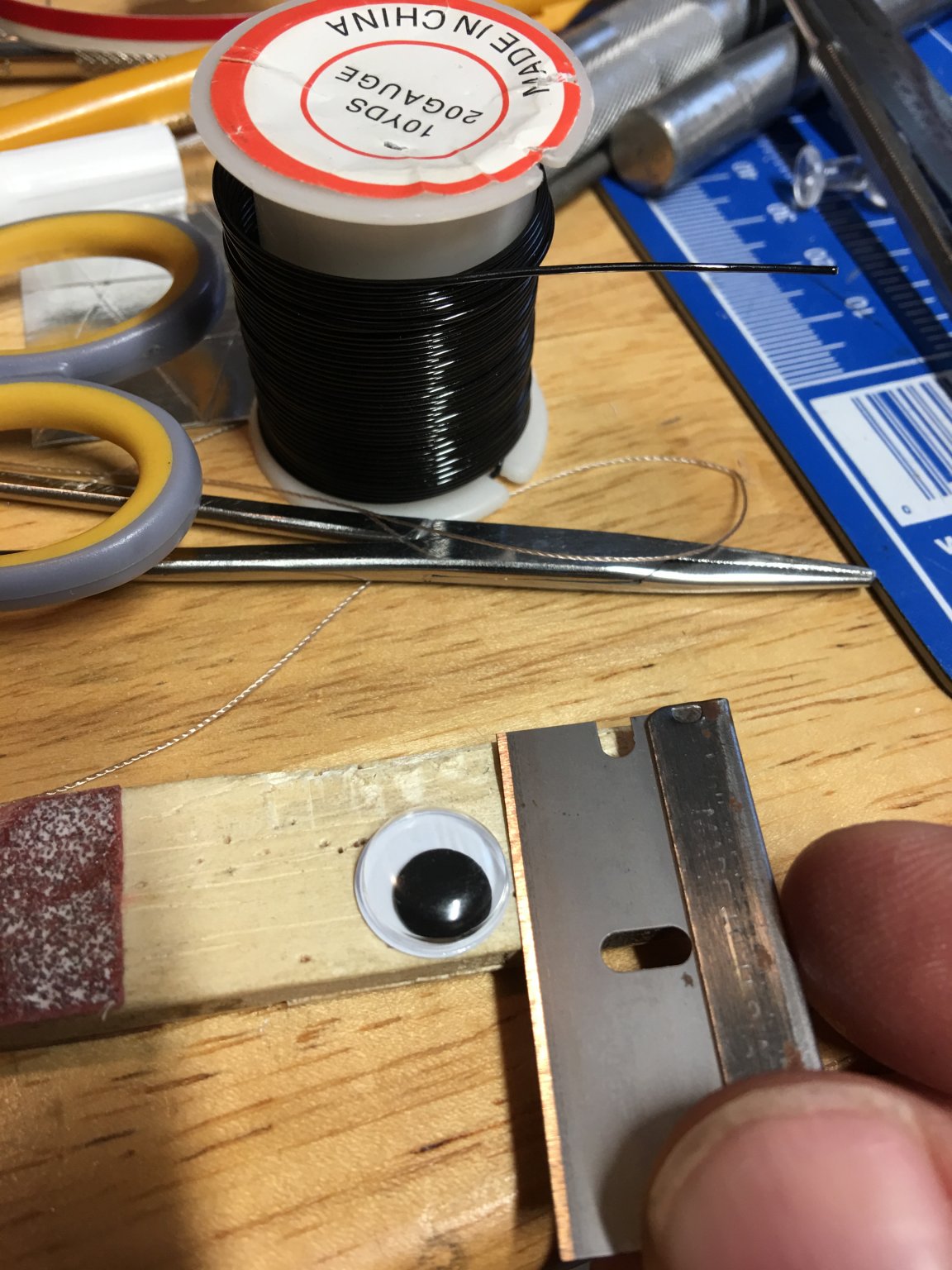
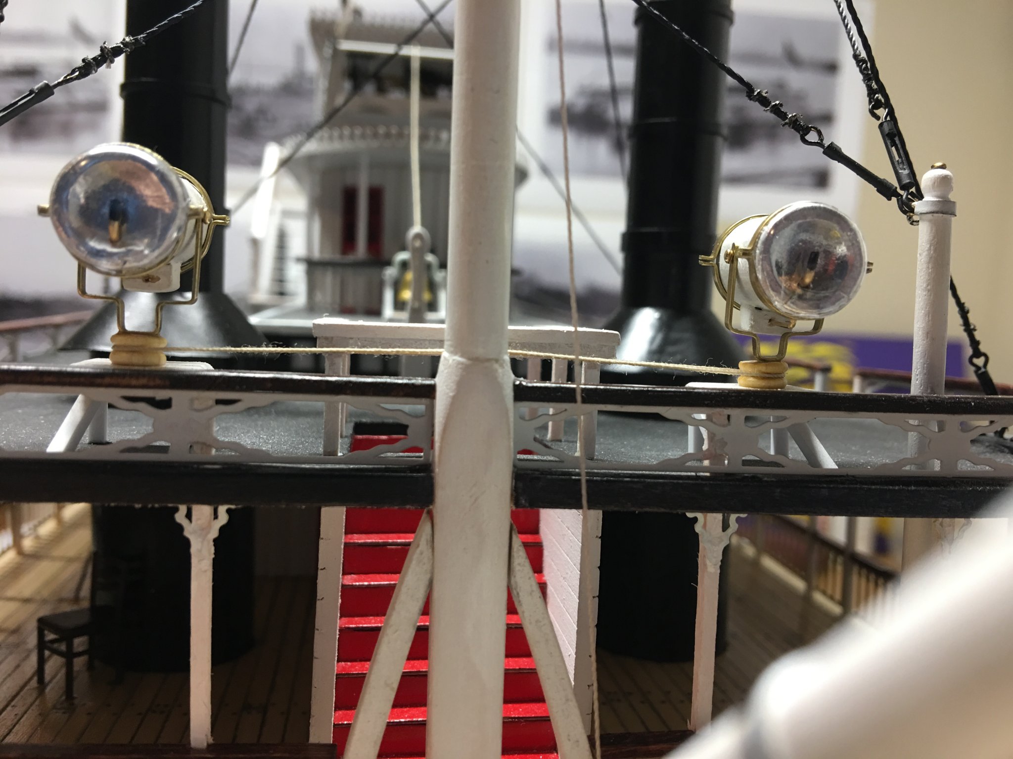
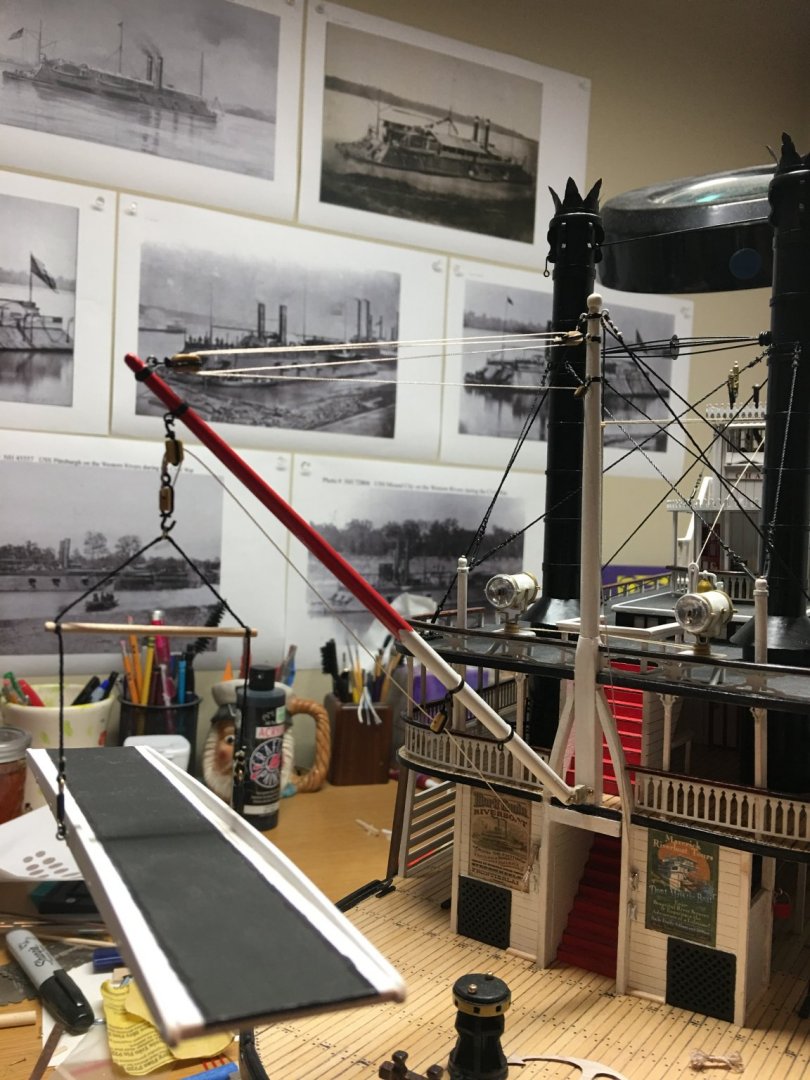
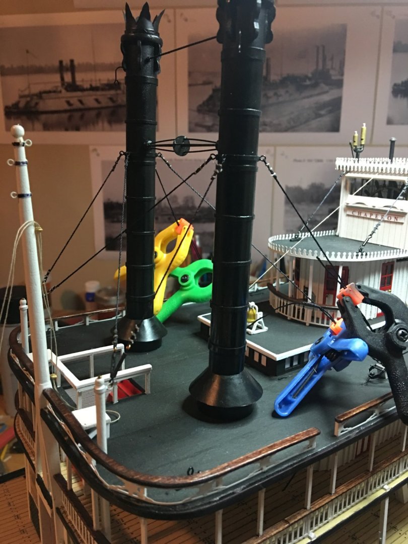
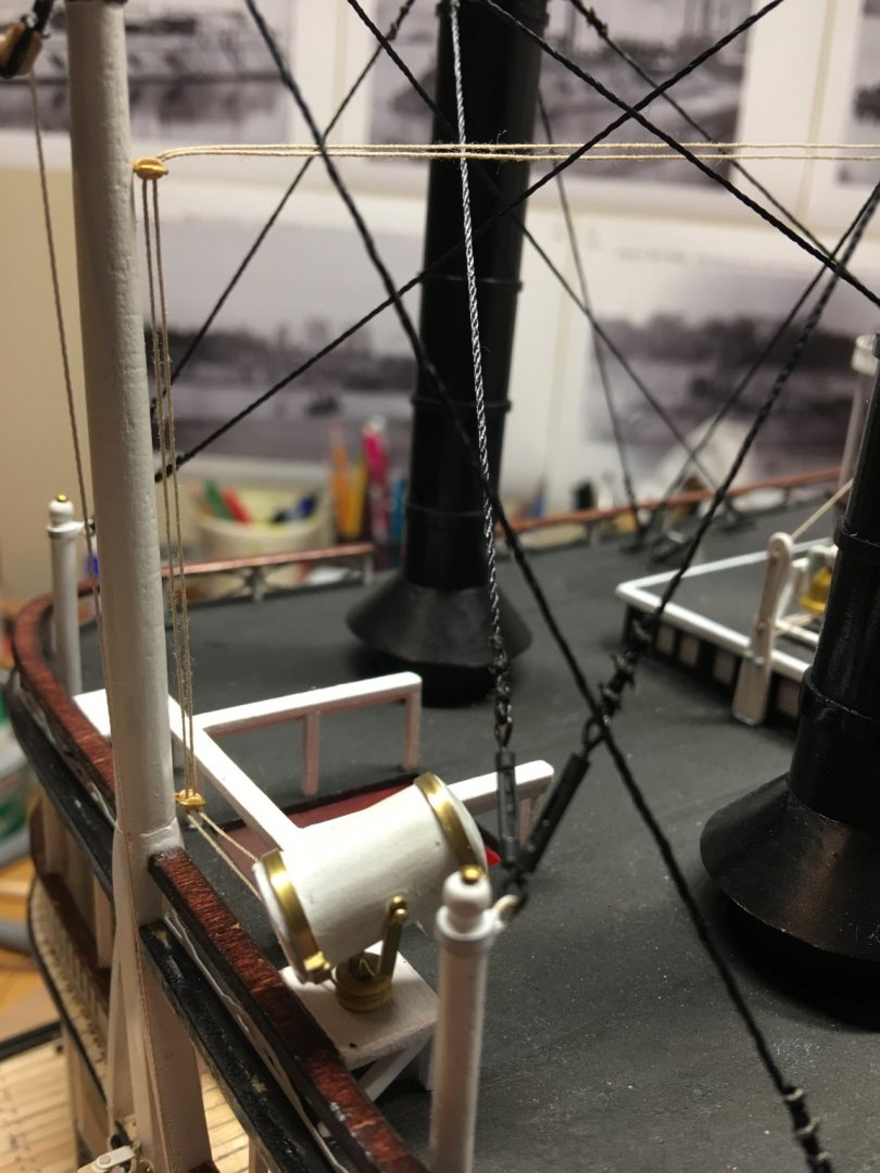
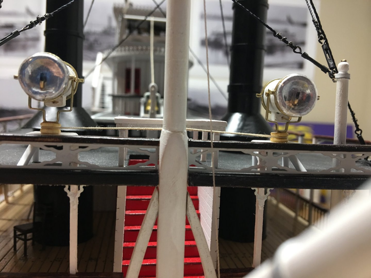
Good morning everyone, This week marks one year that I have been working on this build. I must say my how it has flow by. This week I worked on finishing up on the forward rigging of the chimneys, landing stage, searchlights, mast and boom. Completing this portion really starts to pull things together. It also creates lots of snag points and I am going to have to watch myself when working around these areas or I'm going to be rebuilding some pieces. Tying off the top ropes on the chimneys. Forward turnbuckles in place. Last parts of the chimney rigging going in. Searchlights mounted and the control ropes being ran. Searchlight control ropes completed and upper mast and boom rigging. I was also able to add a little details to the fore deck. I used some leftover dead-eyes to create the rollers on the fore deck fair leads. Lastly, I finally finished the searchlights. I was looking for some old model car headlights to use for the lenses, but I wasn't able to find any that I had in my junk box. I had to ponder what to use for a while, I even tried drying out an old pair of contact lenses that I had, but these just didn't come out right. Then my daughter cam up with the brilliant idea to use googly-eyes for them. This was what my first impression of using them looked like. After having a little fun with this, and much to the disappointment of my granddaughter (she loved the eyes on the boat) I surgically removed the lenses from the googly-eyes, added some brass wire for the filament and then snapped the lenses into place. I couldn't have asked for a better fit. That's all for now. I will work on getting the lower blocks and rigging to hold down the stage, the rope coils and the rest of the bull rails cut out and in place this week. I'll also try to figure out how to mount the lifeboat/work boat booms. Hopefully I will come up with some sort of solution. She is really starting to come together, I can see the finish line in sight. As always, thanks for all the likes and thanks for looking. -Brian


- 133 replies
-
- 11
-
-
- chaperon
- model shipways
- (and 2 more)
-
Wood and plastic. The best of both worlds. Nice looking bunks. Now it’s nap time. -Brian
-
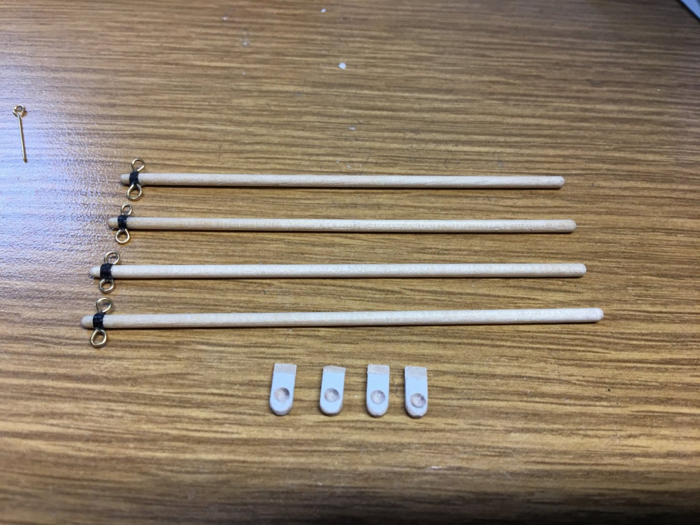
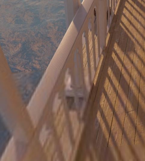
So I have a question. I am coming to the point where it is time to construct the boat booms. The instructions call for two eye-bolts to be linked together and one end inserted into the dowel, the other inserted into the deck to make up the pivot point for the booms to swing out on. This seems like a cheesy way to do it, but I want to get it right. I've looked at the old pictures of the Chaperon and the only one I can find that has a clear shot of them doesn't really have any good detail. I have also looked at Jens Mittelbach's 3D website of Chaperon and from what I can tell he just has the booms sitting in what looks like a socket and the boom just pivots inside of that socket. Does anyone have any clear guidance as to how these were actually built. I'm sure that each boat builder had their own method, I'm really just looking for some common way to build it up right. Thank you in advance. -Brian
- 133 replies
-
- 3
-
-
- chaperon
- model shipways
- (and 2 more)
-
Eric, I thought so to. It seems that every museum I have visited (related to boats, ships, etc..) always has some sort of model in the exhibit. The more I think of it the more my curiosity gets to me as to why such a prominent part of my towns history and culture has an exhibit in the local museum, but no model of it. Bob, I would love to visit Le Claire and see the City of Baton Rouge some time just for the history of it. Maybe even take a ride on the Twilight. I'm sure there are not many people in my generation from my home town that have had a chance to see the actual City of Baton Rouge. I would be nice to say that I have. -Brian
- 133 replies
-
- 2
-
-
- chaperon
- model shipways
- (and 2 more)
-
Yves, Your attention to even the tiniest of details is just amazing. Even if the batteries will be mostly hidden, we will still have your build log to go back and reflect on your accomplishments. -Brian
-
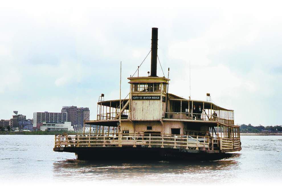
Hello everyone, While I am not quite ready for an update, I wanted to share a little history from my home town. I grew up on the Mississippi River across from Baton Rouge, LA. Unfortunately for me the only way to get across the river from Port Allen to Baton Rouge was by either the new bridge (Horace Wilkinson Bridge - b.1968) on Interstate 10 or the old bridge (Baton Rouge Huey P. Long Bridge - b.1940) on State Hwy 190. However, before my time (just slightly) there was a ferry that ran between Port Allen and Baton Rouge from 1820 to 1968. While the construction of the "Old Bridge" helped save time getting between the west and east sides of the river, it wasn't until the construction of the "New Bridge" that led to the demise of the ferry route (two months before I was born). One of these ferries that shuttled cars and pedestrians was the City of Baton Rouge which ran from 1917 to 1968 and is featured heavily in an exhibit in the West Baton Rouge Parish Museum, as well as painted on buildings and signs all over town. As kid I frequented the museum often due to my love of history. The reason I bring this up was, I was looking at ideas for future build projects and during my last visit to the WBR Museum a few years ago, I noticed that with all of the pictures and artifacts the museum had related to the old ferry system and there was no models of the ferry itself. I didn't give it too much thought at the time since my focus was on pre-20th century sailing ships and not steamboats. It wasn't until I started my Chaperon build that my interest really switched to steam power and its history. So I figured that since I grew up around this type of culture, why not build something from it. Right now I am seriously thinking of doing a scratch build of the USS Cairo as my next project, but depending on how that build goes, the City of Baton Rouge could be after that. Who knows, since the WBR Museum doesn't have a model for their exhibit, maybe I could donate mine (we'll see how the build goes first). My apologies for hijacking my own build for this, I just found it interesting and thought I would share. Here are a couple of photos of the ferry during her hey-day and just before she was taken out of service. Photos are courtesy of the West Baton Rouge Museum. The City of Baton Rouge is still around today. When she was taken out of service in 1968, she was converted to a wharf boat for the excursion boats Twilight and Julia Belle Swain in Le Claire, Iowa. Here was an article posted in the Baton Rouge newspaper on the 100th anniversary of the City of Baton Rouge. https://www.theadvocate.com/baton_rouge/entertainment_life/article_4316a0ae-a54b-5800-92ef-1b914f398cdb.html Thank you for looking. -Brian

- 133 replies
-
- 7
-
-
- chaperon
- model shipways
- (and 2 more)
-
Masterful work Eric. I’m right there with you. Adding cargo and other deck details really starts to pull the whole thing together. I like the technique of using the masking tape to give the chimneys that “hammered” look. If I had known about this sooner I would have definitely incorporated that into my build. -Brian
- 599 replies
-
- 3
-
-
- sidewheeler
- arabia
- (and 4 more)
-
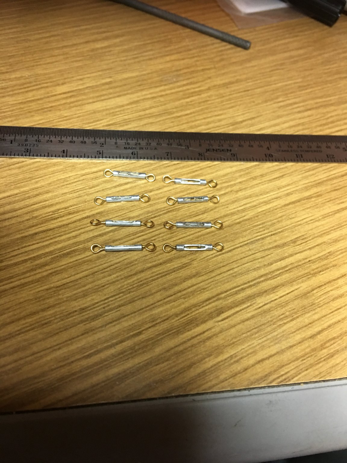
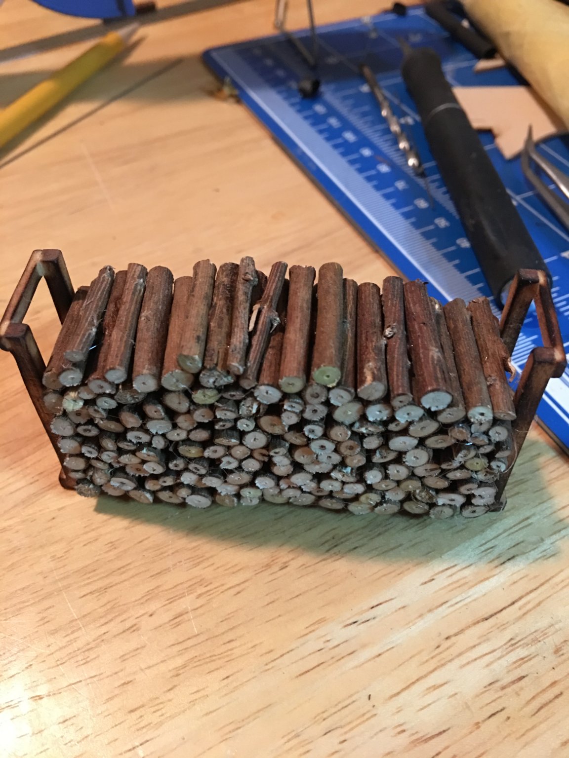
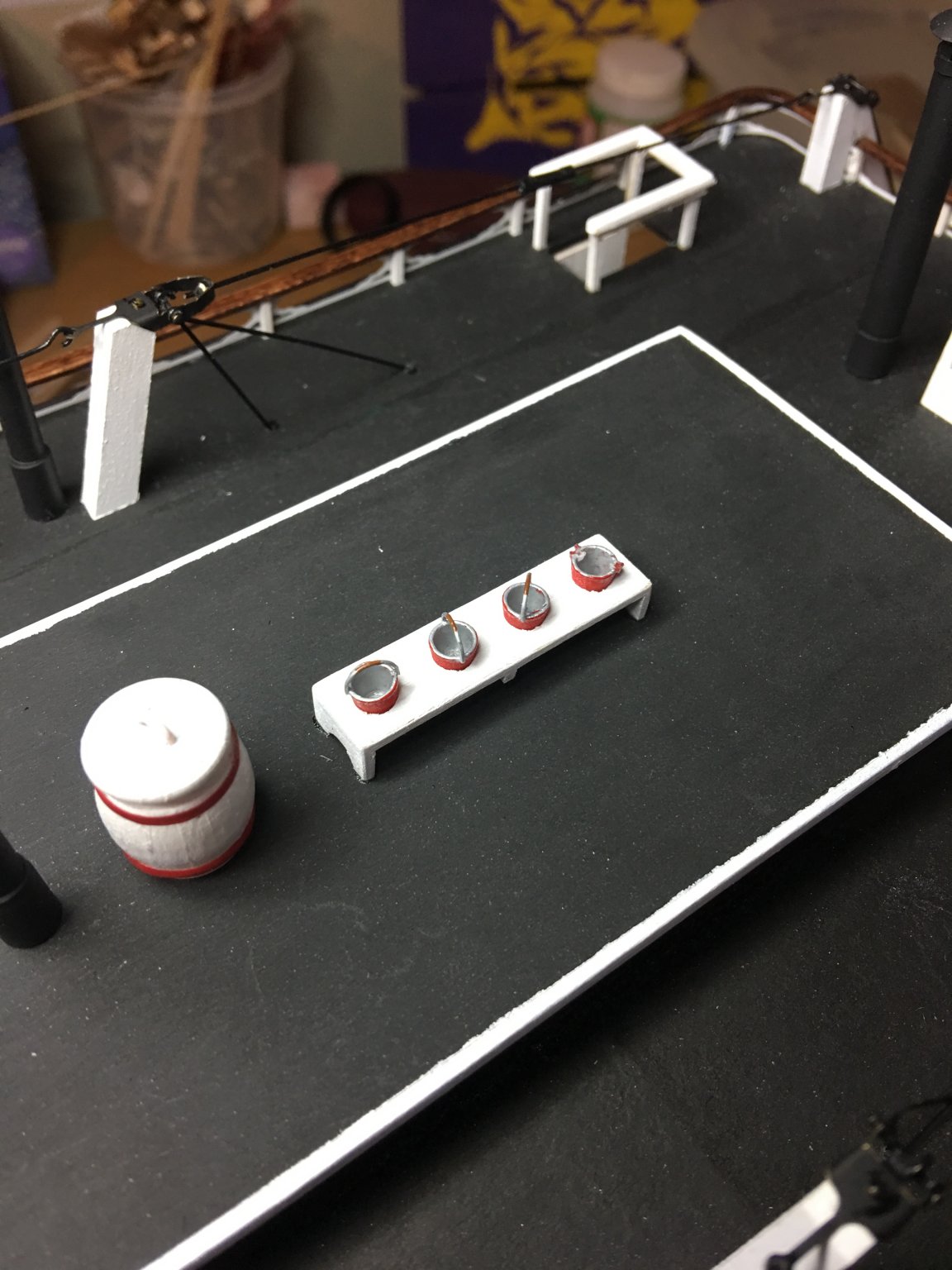
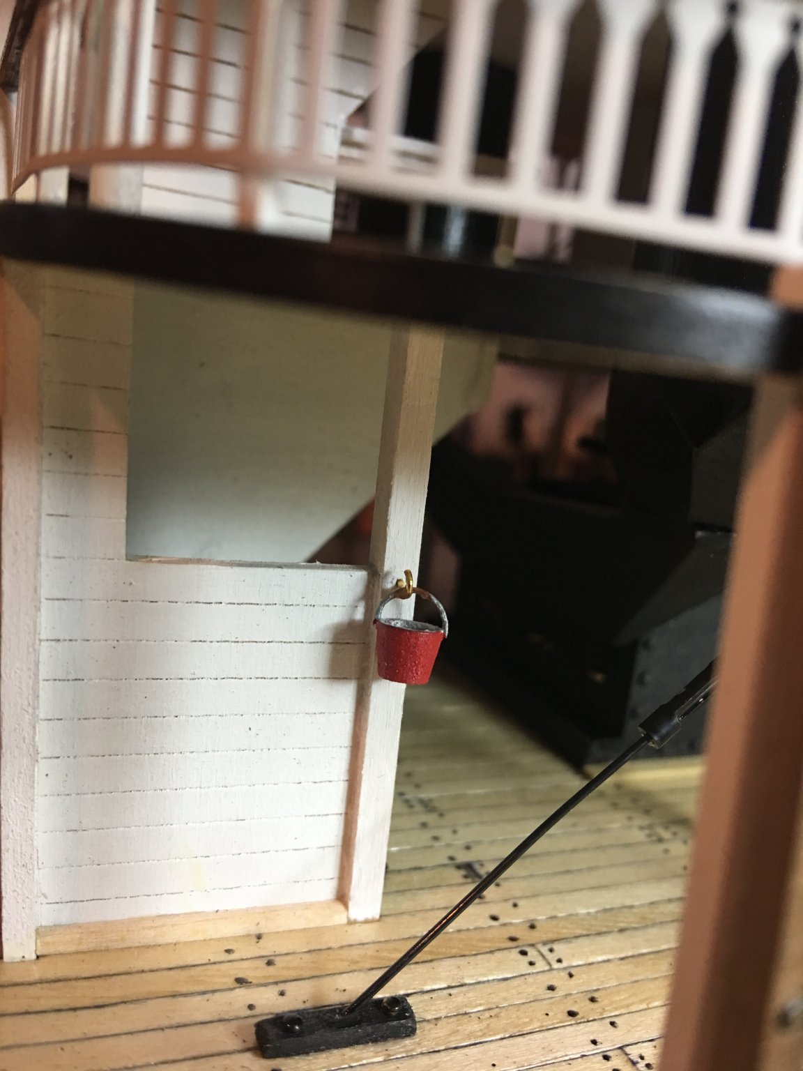
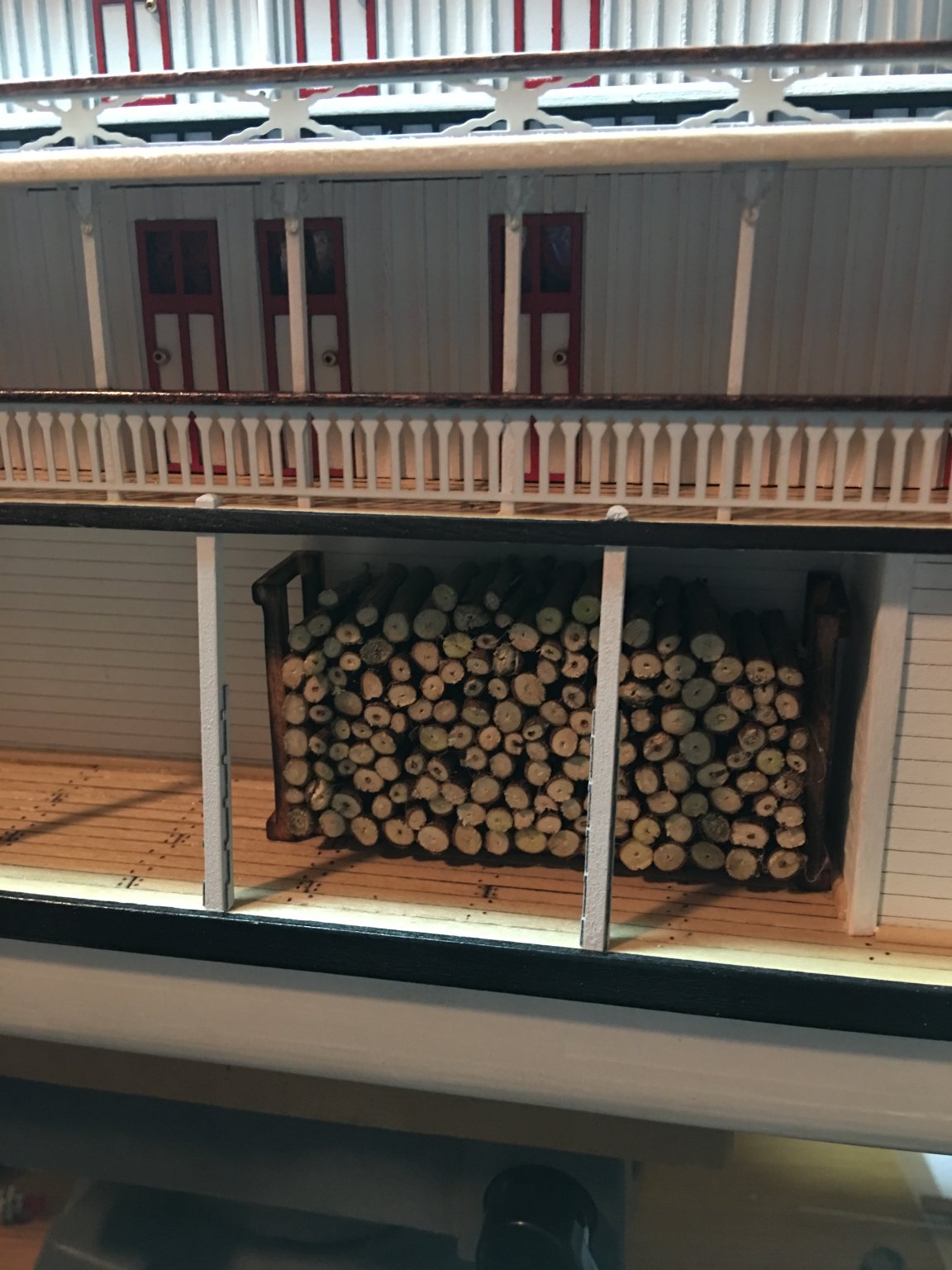
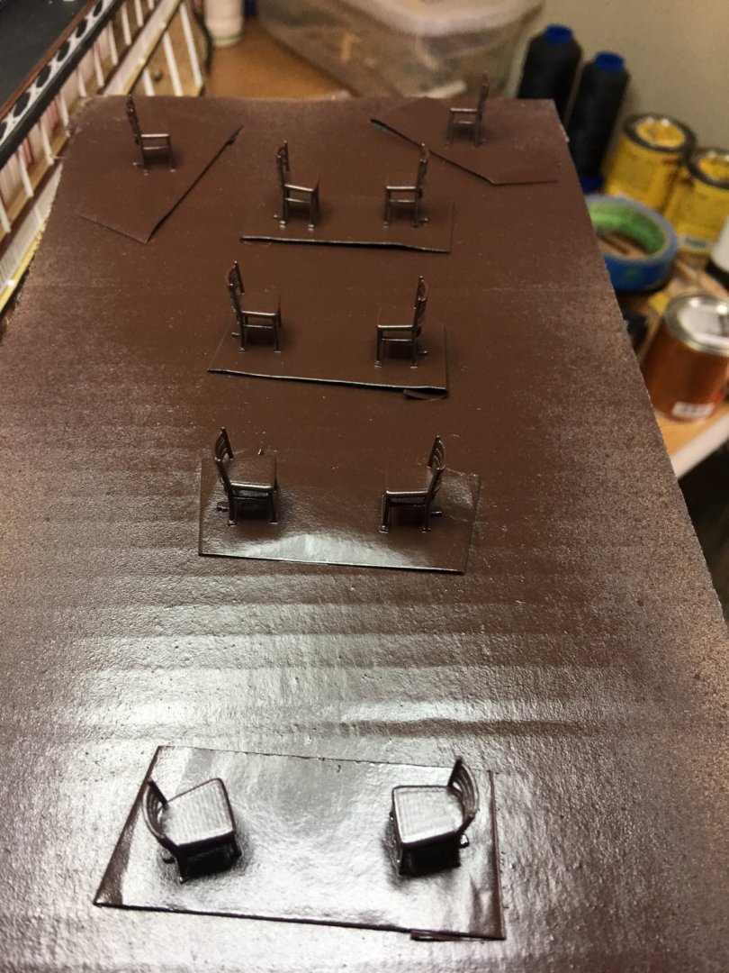
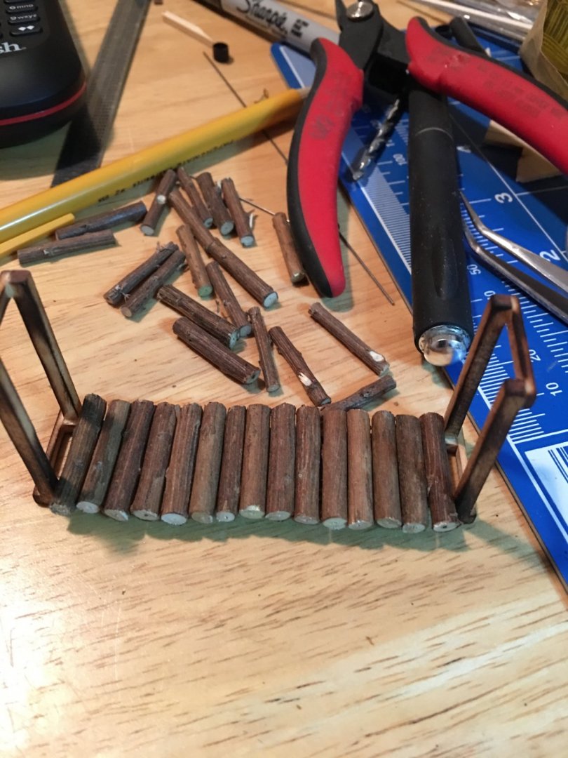
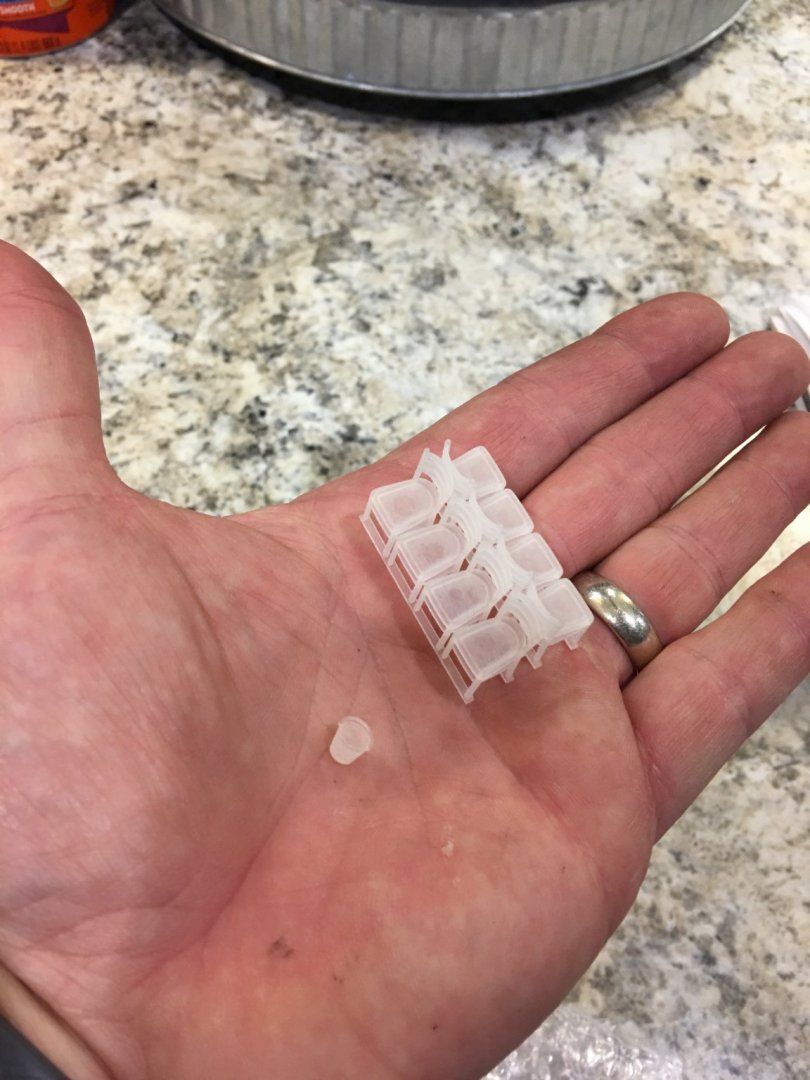
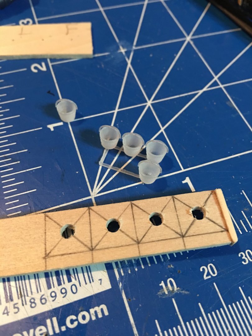
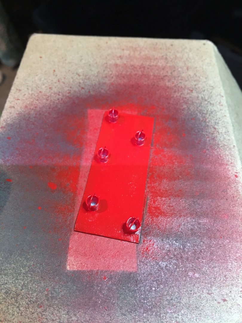
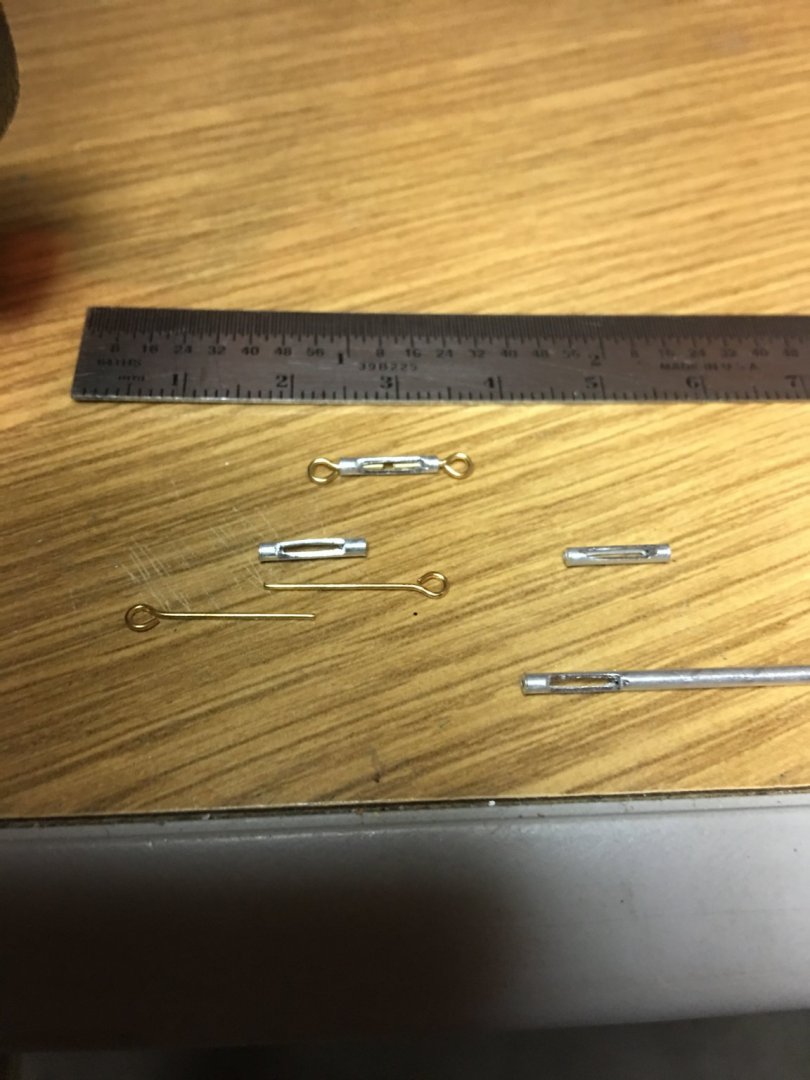
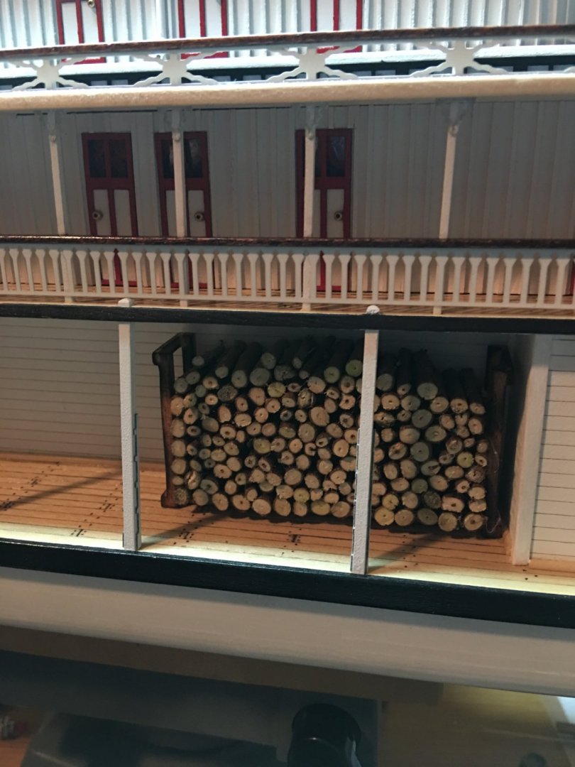
Good morning everyone, Small little update, this week we had absolutely beautiful weather (with the exception of Friday) so most of my time was spent outdoors getting other projects done. I did manage a little time on my build though, and here is what I accomplished. I managed to get the turnbuckles fabricated. Tedious project to say the least. Several breaks were needed due to my hands cramping up holding these tiny things, but I got them done. For these I used some 1/16" aluminum tubing and filed the sides flat. I cleaned up the slots with an exacto blade and used some 24 guage brass wire to make the 1mm eyebolts. They have since been painted and I'll let them dry before installing them and rigging the chimneys. Next, I worked on more deck details and built up a firewood rack. Nothing fancy, just found some twigs around the property and cut them to length and made up the wood rack with spare wood laying around. A little weathering with the torch and some golden oak stain and here is the result. Lastly, I ordered some miniature deck furniture from Shapeways. The detail on these 3D printed parts is fantastic, a little pricey, but worth it for the detail. I purchased some fire buckets and deck chairs and got them painted up. I build up the fire bucket rack for the hurricane deck, added a firewater barrel and placed a couple of other buckets around the boilers. The chairs are a little brittle, so I will be placing them around the decks when I get closer to finishing so I don't break any. That's about all I have this time. I should have more next time since the forecast is calling for rain all week. Now that the turnbuckles are complete and dry, I'll work on getting the rigging for the chimneys done and who knows what else. Thank you for looking and all the likes. -Brian


- 133 replies
-
- 7
-
-
- chaperon
- model shipways
- (and 2 more)
-
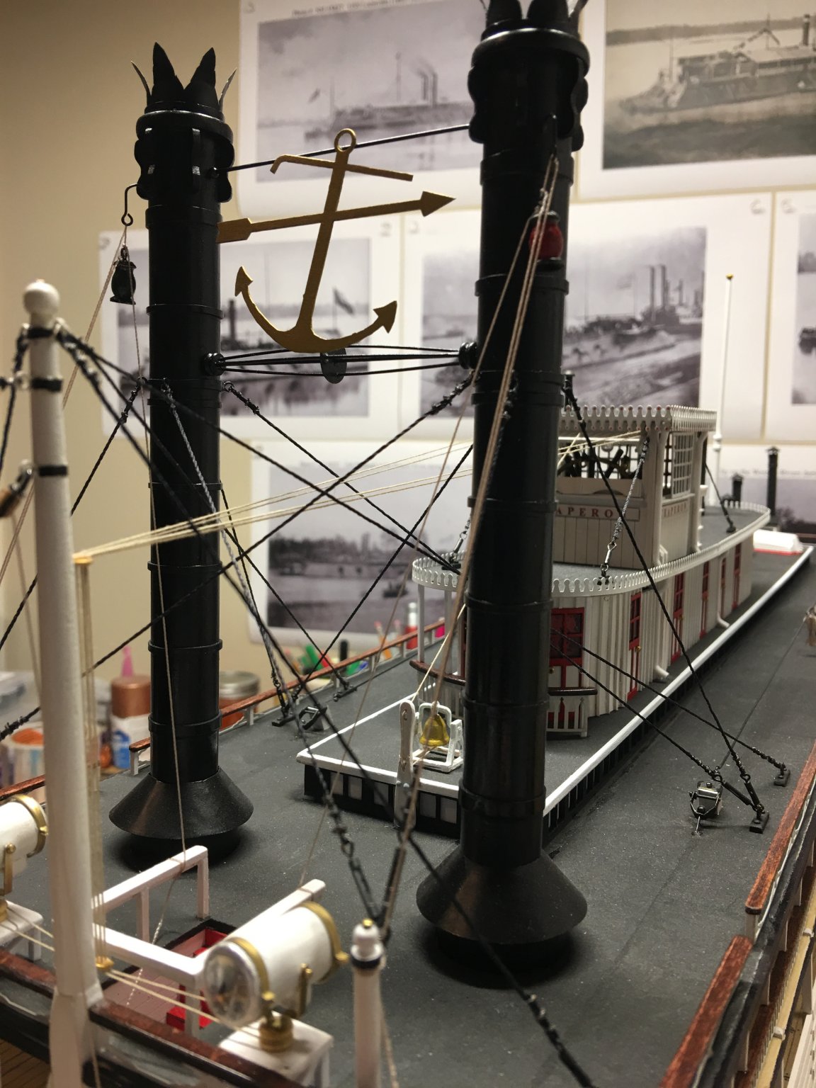
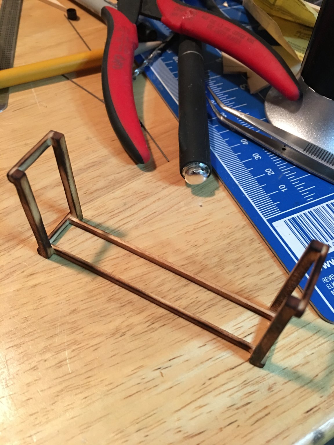
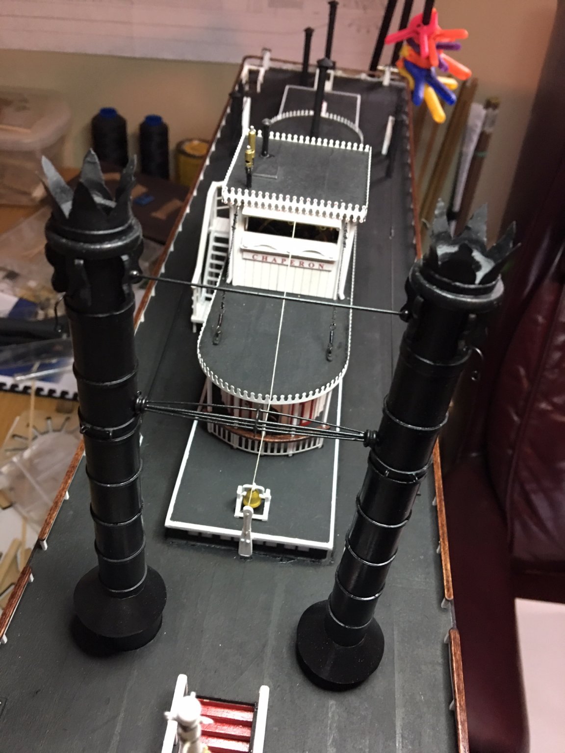
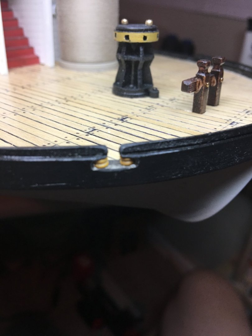
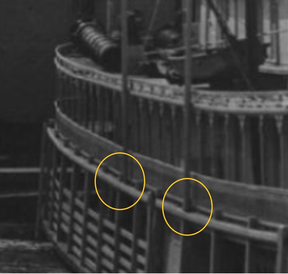
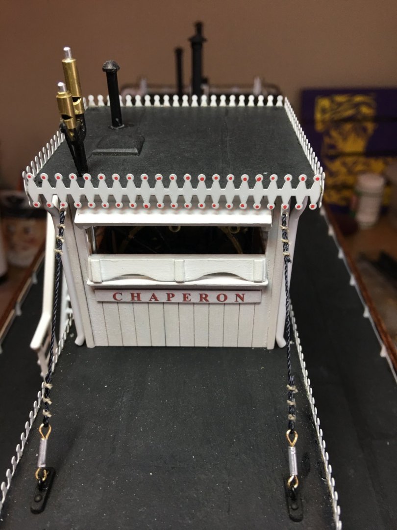
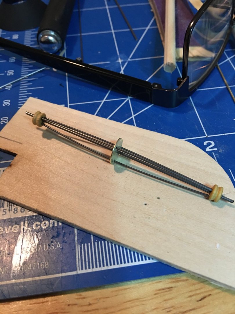
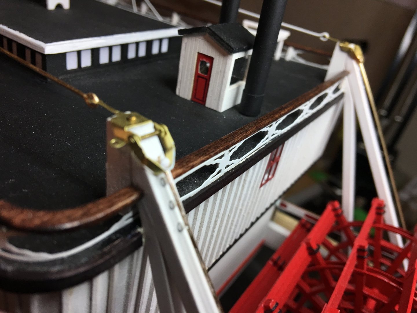
Roger, Thank you for the helpful tip. I found a couple of yawl boat ideas that I may incorporate into my build. Eric, You hit the nail square on the head with this one, "it's all the little details that make this so much fun to learn about". I have to say that of all the builds that I have done, this one has been by far the most fun. I have learned so much more about steam boats than I would have dreamed, and still have only scratched the surface. As for the pilot house info, I kind of figured that was why they tied them down. Going back to one of Kurt's comments he made a while back in this log, and as you referenced here, these boats were built on a shoestring budget so they did what they had to do to keep the boats together as best as possible. So to expand on this a little further, or maybe just pick y'alls brain a little more, were the tie downs made from rope or from steel bars with turnbuckles (like the hog chains), or something different? Going by the instructions, the pilot house tie downs are simple cables tied to eye-bolts in the Texas Deck roof. On Dr. Jens Mittelbach 3D rendering of Chaperon, he shows what look to be iron bars with turnbuckles connect to the eye-bolts. I tried zooming in on several of the old pictures and it's hard to tell what was used on Chaperon. I went ahead and used my own interpretation of these tie downs and made a hybrid of cable and turnbuckles. Once I completed the pilot house, I finished the Texas deck railing and posts. The last thing completed this week was the chimneys. The decorative separator was a little bit of a challenge to get just right, but for the most part I think it turned out pretty well. I used a couple of small deadeyes for the end pieces and scratch built the center spreader wheel. The decorative tops of the chimneys were cut from a thin sheet of copper and bent to shape. After assembly and a coat of paint, I think the whole thing looks pretty good. Now to finish the anchor points for the chimneys and mast and hopefully start on getting her rigged up as soon as get all of the turnbuckles made up. Thank you all for the great information and the likes. -Brian


- 133 replies
-
- 7
-
-
- chaperon
- model shipways
- (and 2 more)
-
Roger, Welcome to the party. It's never too late to join in. Thank you for the insight on the work boats, I'll definitely look into adding that to my build as well as looking for Howard Chapelles book (could be useful if I have to scratch build one of these boats). I had never even thought about them using the boats to tie off to the shoreline, I figured they were just for emergencies or for use as tenders. My impression of them docking was that they would just pull up to the banks, drop the stage, have the deck hands haul the rope out, then use the capstan to tighten the line. It all makes sense now. As for the Chaperon carrying passengers, that was one of her primary roles, shuttling passengers on the Ohio, Barron & Green Rivers. Even as the J.C. Kerr she carried passengers, so I'm sure since she was built in 1884 she would have fallen under the Steamboat Inspection Service since it was created in 1871. When I started this project I had very limited knowledge of steamboats, but through this build, research and conversations with those (like you, Cathead, Kurt and others) that have studied them for years, I have learned a lot. -Brian
- 133 replies
-
- 1
-
-
- chaperon
- model shipways
- (and 2 more)
-
So I have a question that has been rattling around in my little pea brain for a while. While I was installing my pilot house and securing the tie downs, the thought occurred to me as to why these were needed. I know that these boats were not known for their blazing speed, and surely running up and down the shallow western rivers with all their twists and turns that they were not running full steam ahead all the time, what would the need be to secure the pilot house to the deck with tie downs. Were they just not that structurally sound to withstand a stiff wind should a sudden storm pop up or did the open window in the front act as sort of a wind drag that caused lifting on the house itself. Just curious because in studying pictures of numerous different boats, tie downs were not used on all of them. -Brian
- 133 replies
-
- 2
-
-
- chaperon
- model shipways
- (and 2 more)
-
Eric, I love the way the roof came out with your technique. The tape better defines the tar paper lines. The silkspan that I used on my build was a little thin and really can't be seen with the exception of where the Modge Podge "oozes" out between strips and the paint is a little shinier that the rest of the roof. I may have try this method on my next steamboat build. Also, a nice view is always a plus to have when spending hours at the work bench. I wish my bench was that clean (I'll definitely have to work on that). _Brian
- 599 replies
-
- 3
-
-
- sidewheeler
- arabia
- (and 4 more)
-
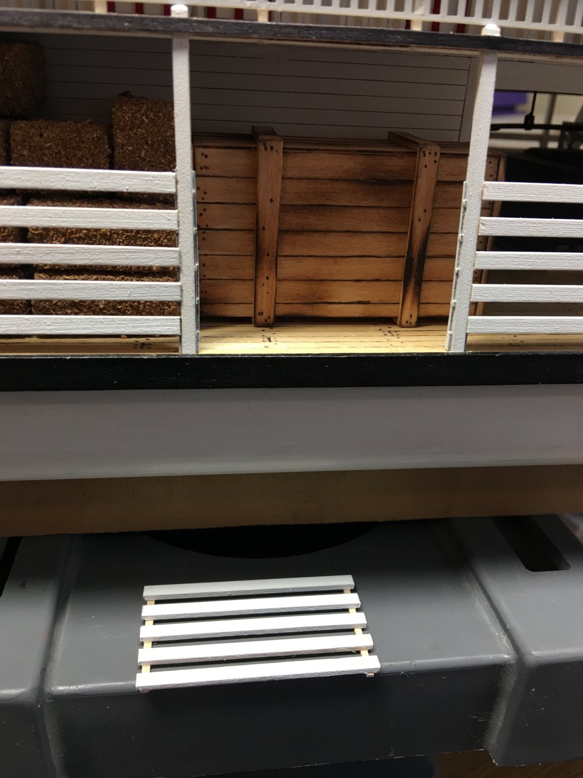
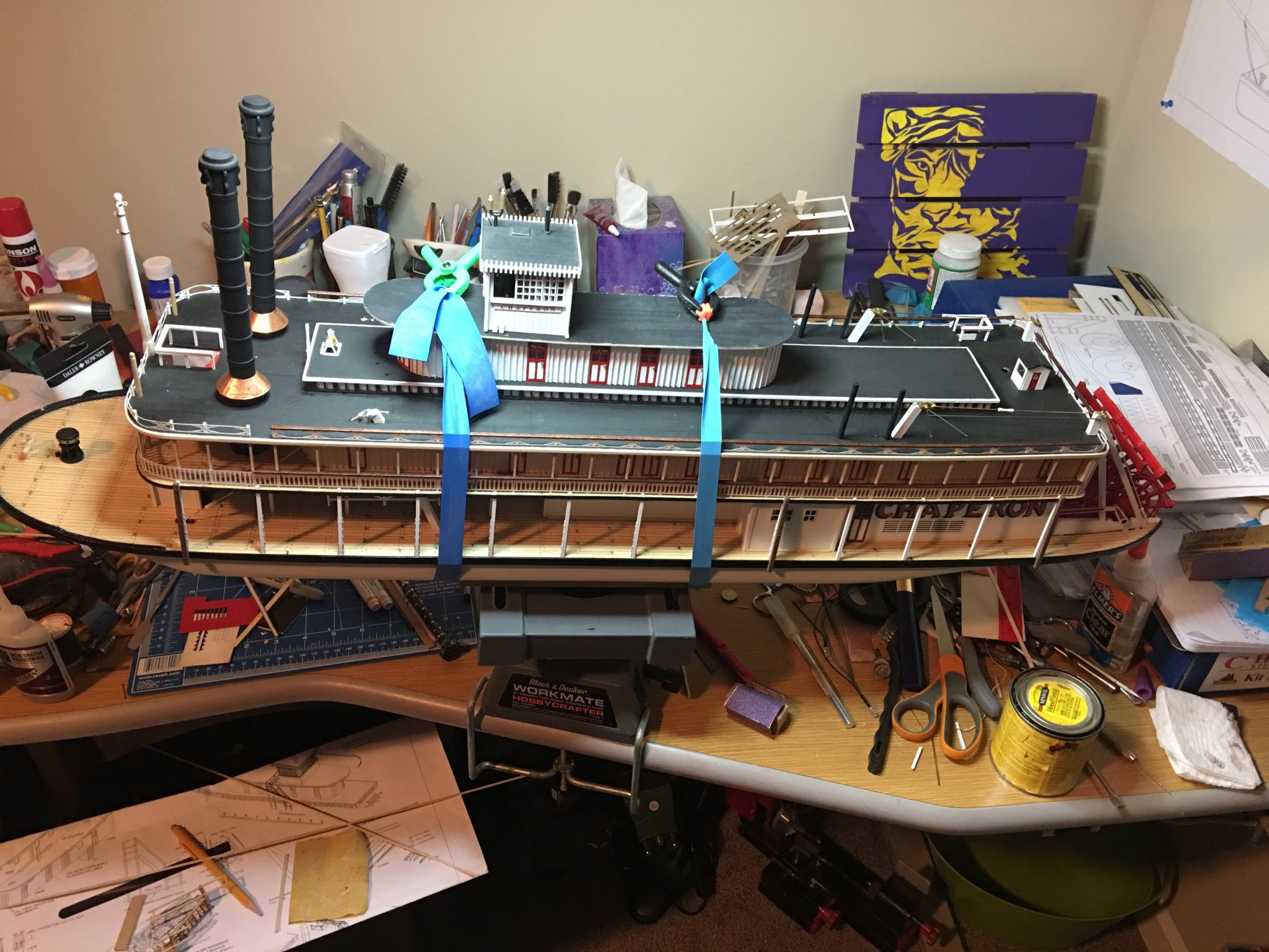
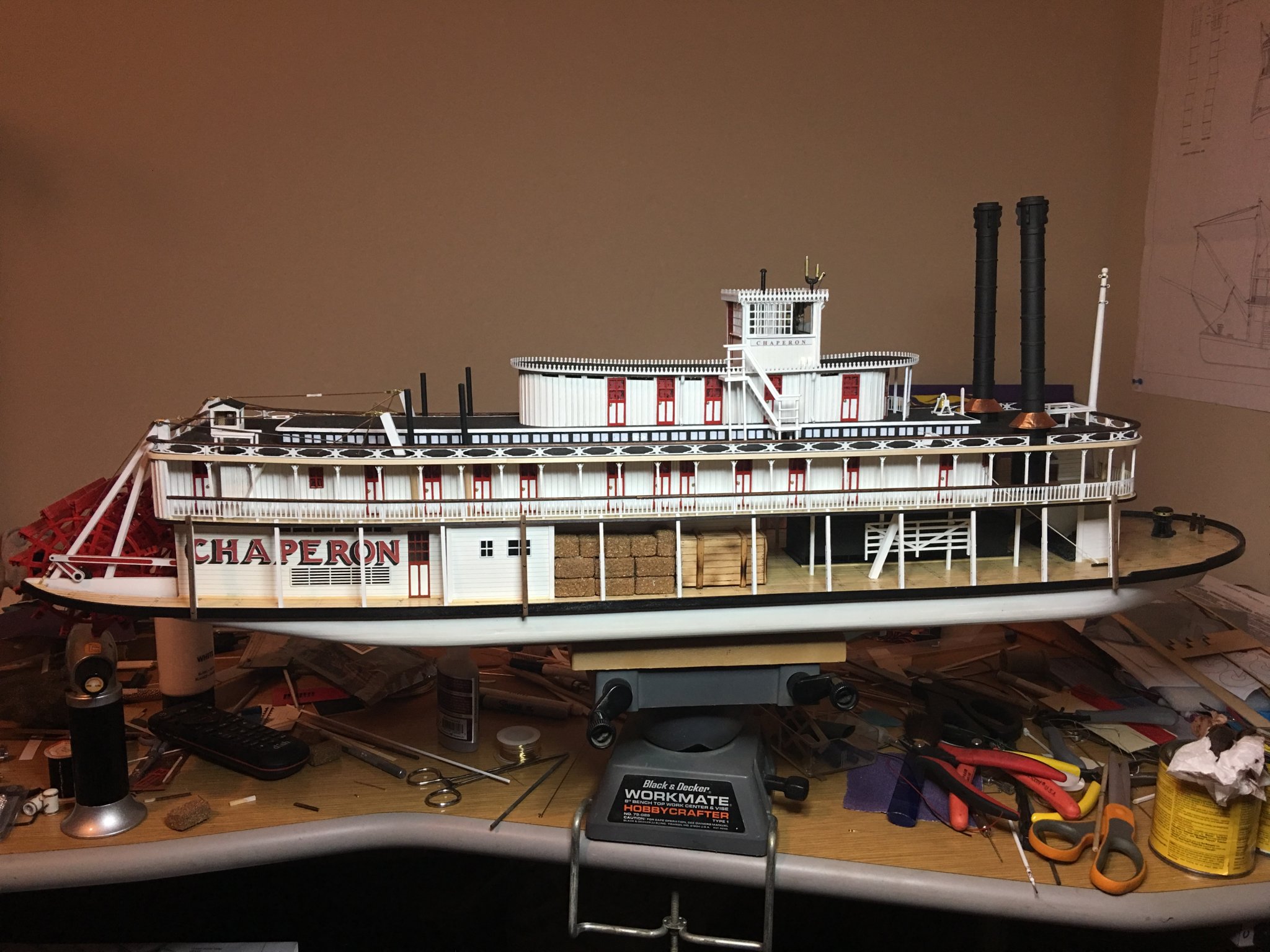
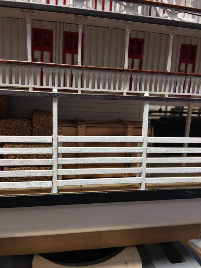
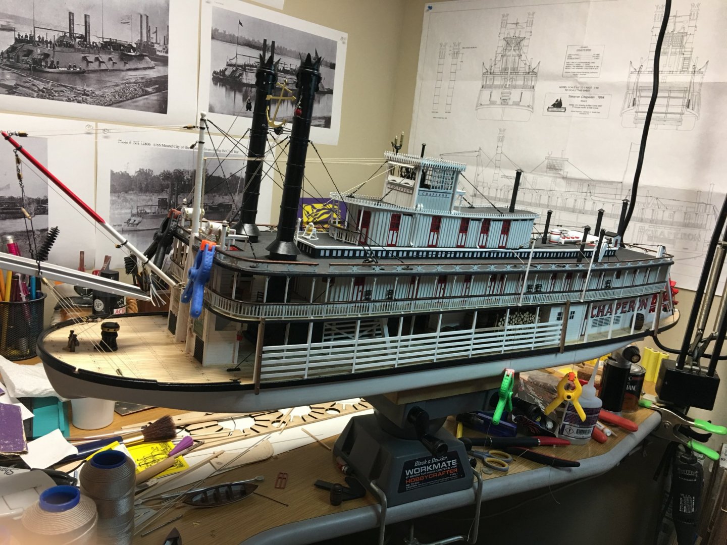
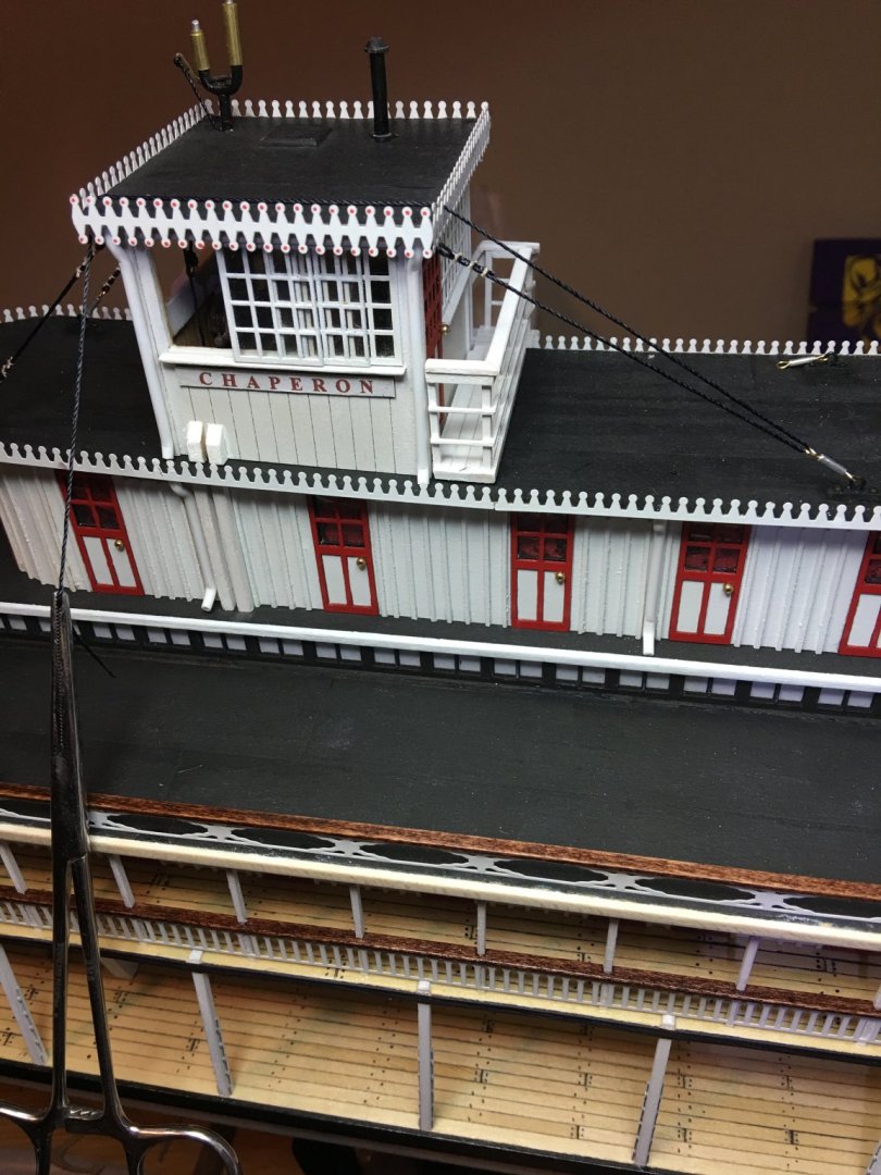
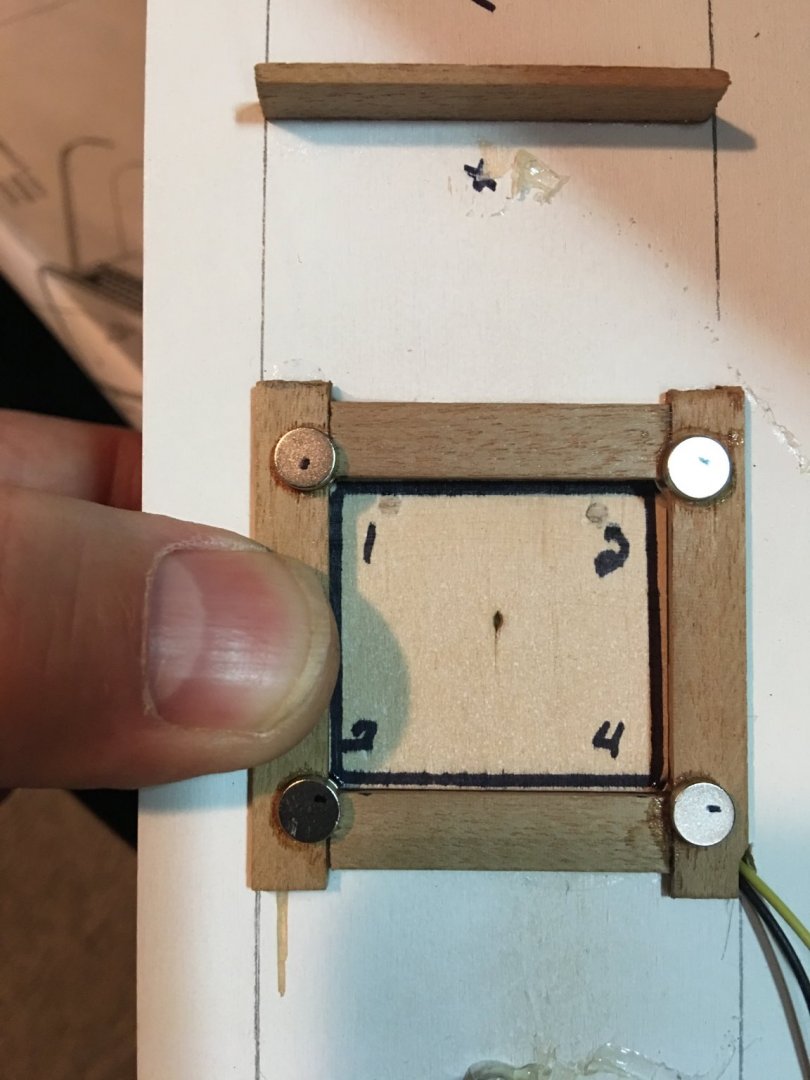
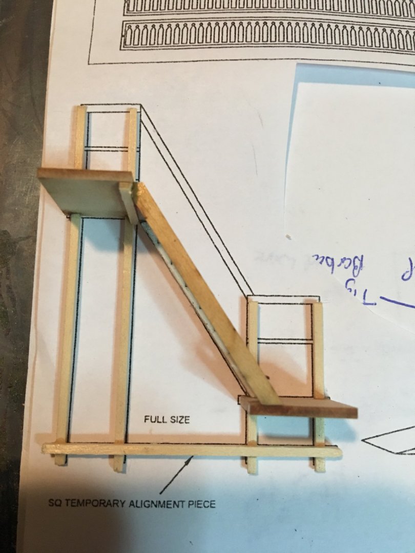
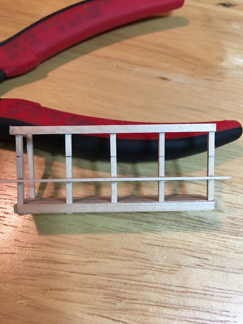
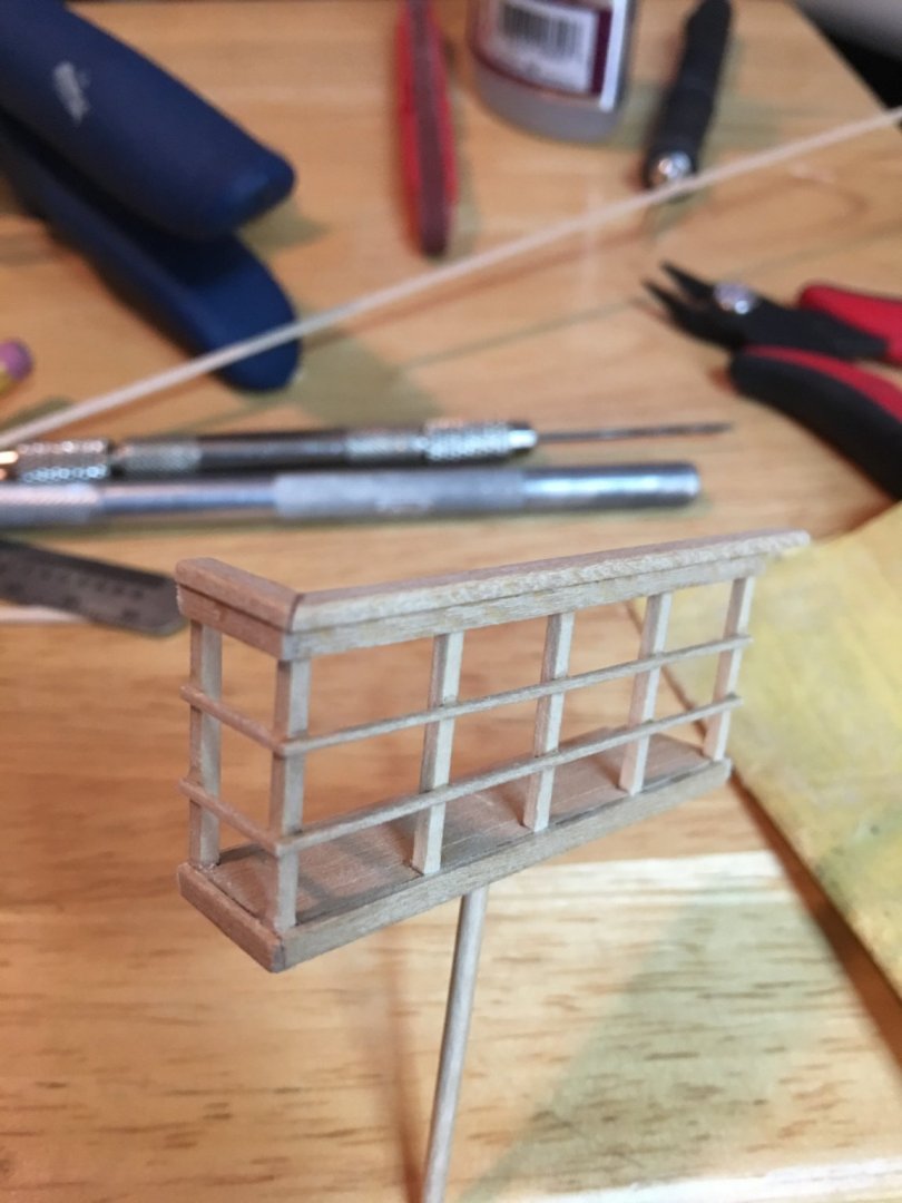
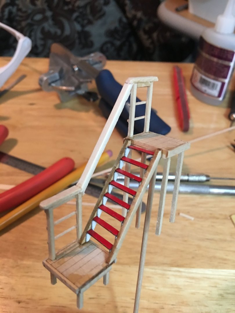
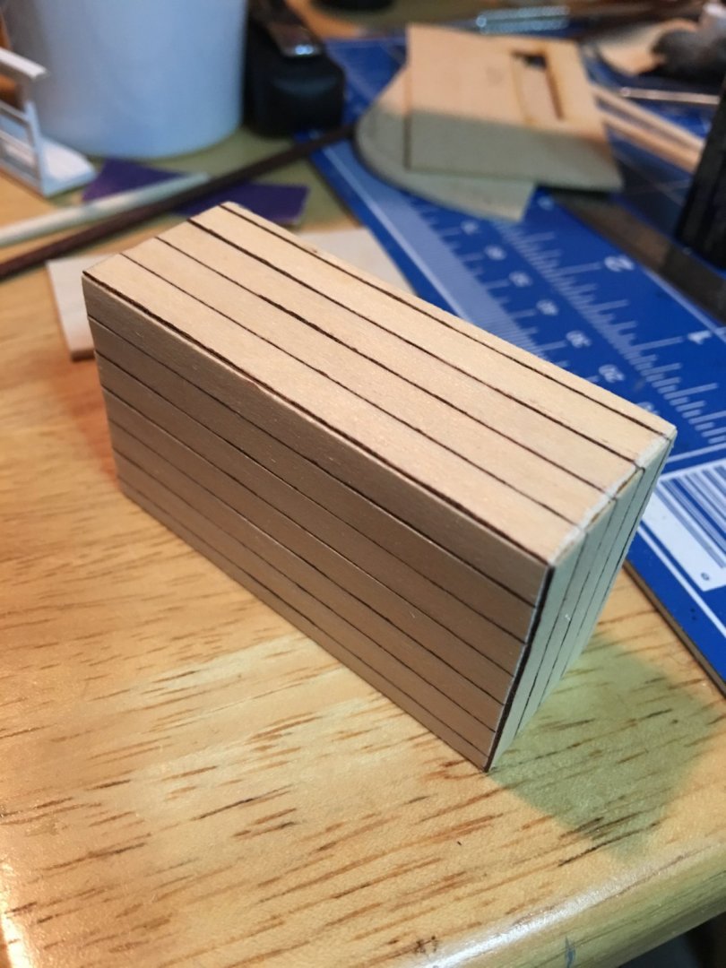
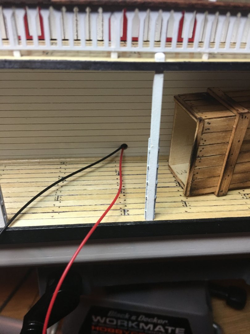
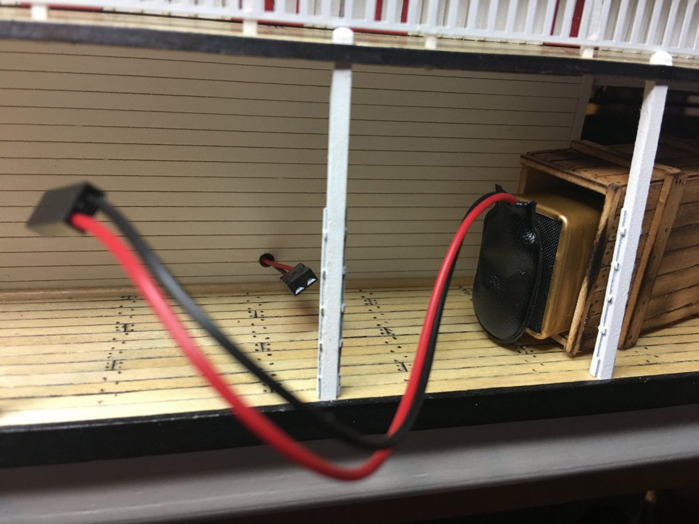
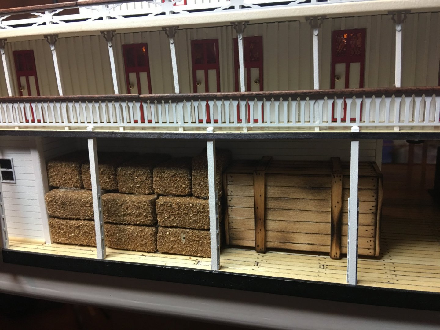
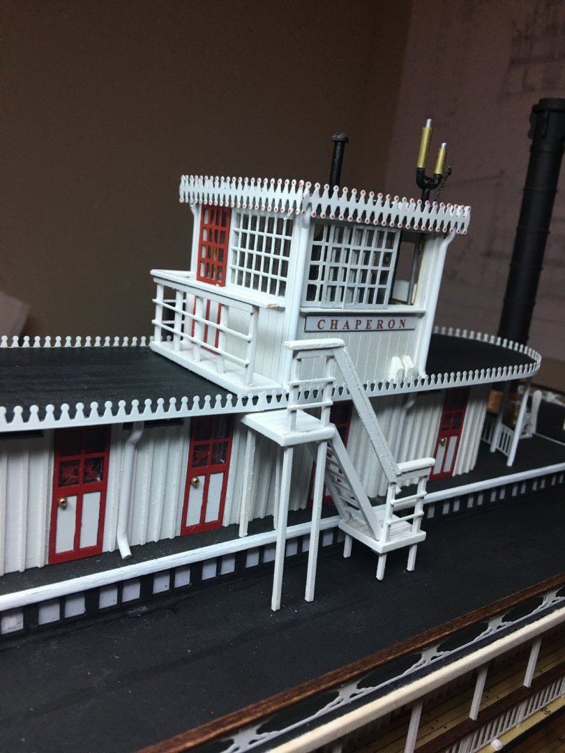
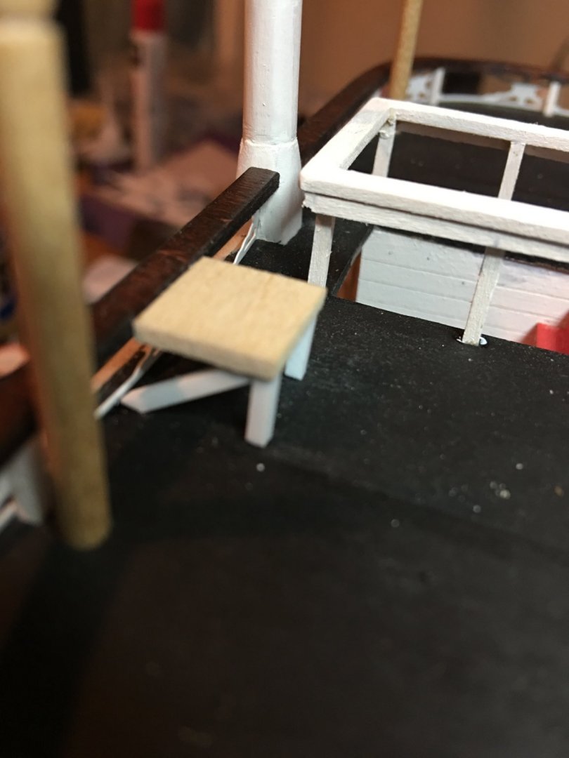
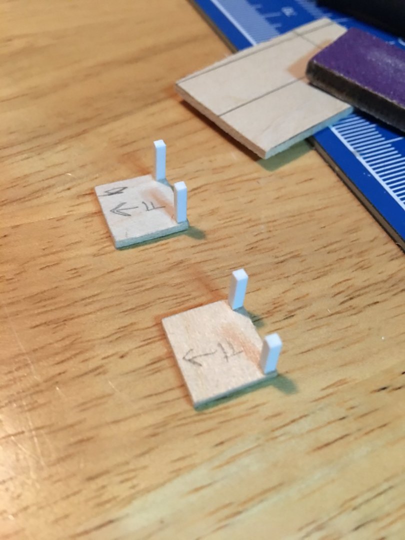
Hello all, More work done this week on my Chaperon. I completed the installation of the pilot house and its stairway along with a "battery" crate that will hide the 9v battery for the lights. I have to admit, I am a little bit ashamed of myself for not planning this one out a little better. My thinking when I first started this build was to use an external power source for the lighting much like I did for my KotM build. But as things progressed I decided that I would just go with battery power instead. I would run all of my wires up to the Texas deck and terminate them there. I was going to make the pilot house removable so the battery could be changed out when needed. This was the plan all the way up until this week when I realized the when I was installing the magnets to hold the pilot house in place that there is a whole slew of rigging and tie downs that are attached to the structure, and there was no way that I was going to remove all of that to swap out batteries. Here is the pilot house magnets going in. Magnets in place and the Texas deck roof being glued down. It was at this point that I realized this wasn't going to work. So I came up with an alternative solution. I wanted to add a touch of life to the model by adding supplies to the decks, much like the crates I built for the main deck earlier in the build, so I figured that a nice big crate and some hay bales would work to conceal the battery . Here is what I came up with. The crate I made from spare planking strips and leftover plywood. I snaked the wiring down from the Texas deck to come out the side of the Main deck wall. Added a little aging to the crate with a small torch and some golden oak stain. Placed a connector on the wires and attached some small magnets to the crate to hold it in place, but still be removable. Threw on a few miniature hay bales and here is what I ended up with. Once I get to installing the bull rails, I will make a couple of them as panels to they can also be removed to get to the battery crate. Next I worked on the pilot house stairs and got them installed. Stairs and walkway in place. I just need to finish tying together the railings and I'll be done with this portion. And here is how she sits right now. My next step is to clean up my work bench. I didn't realize it until I posted this picture how messy it was. Sure didn't take it long to get this way. Now to work on the pilot house tie downs and the chimneys (after I tidy things up a bit). As always, thank you for the likes and for looking. -Brian


- 133 replies
-
- 13
-
-
- chaperon
- model shipways
- (and 2 more)
-
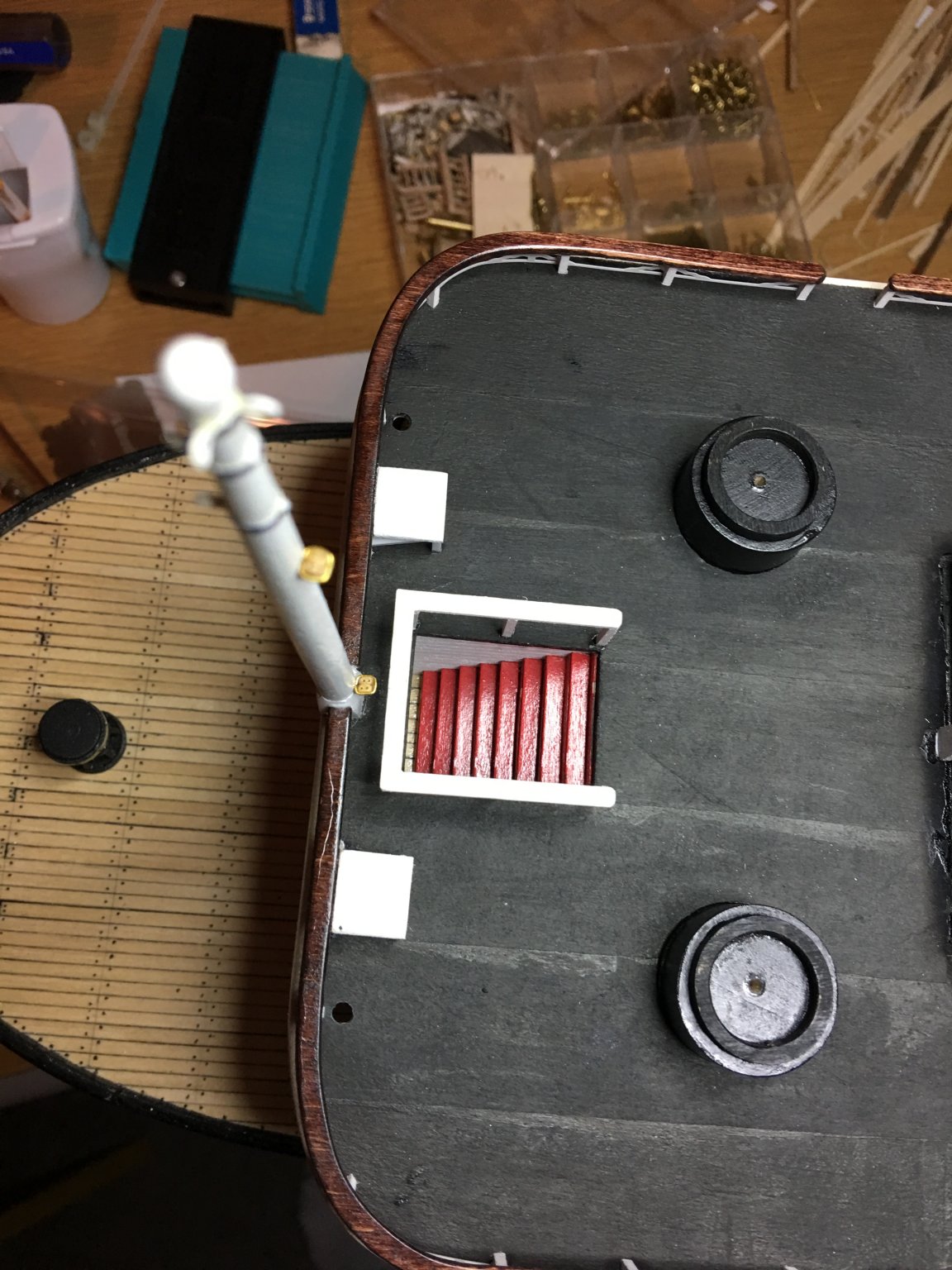
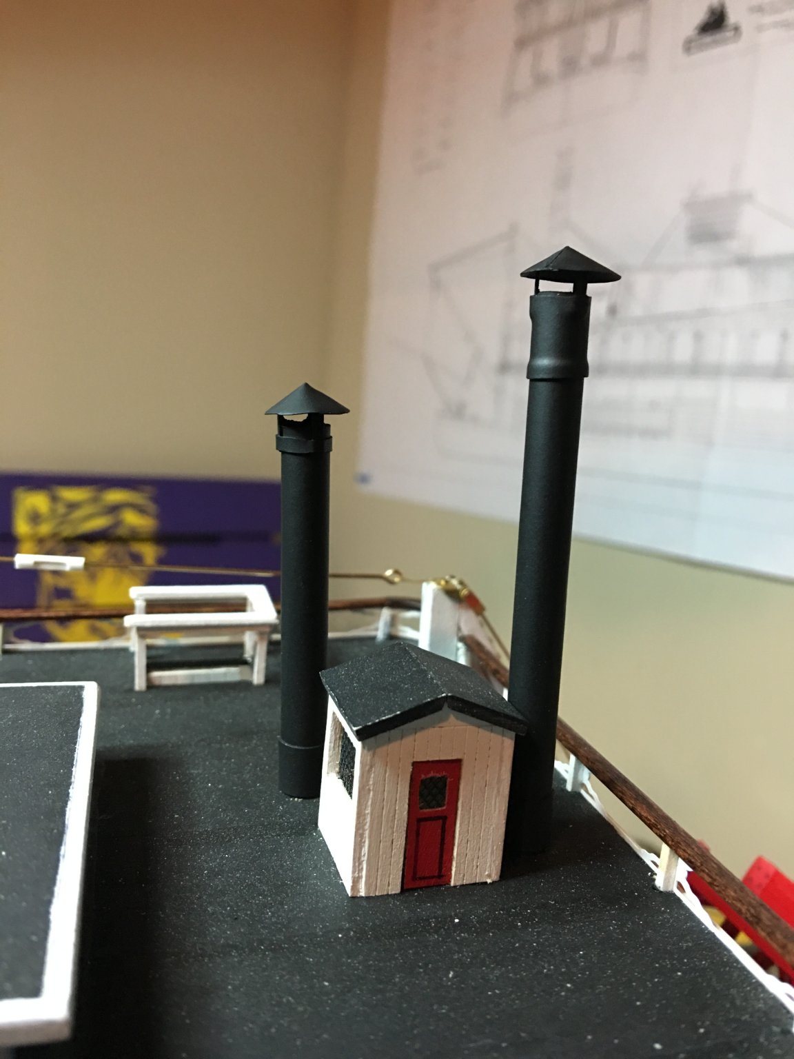
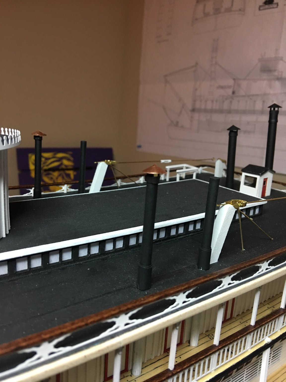
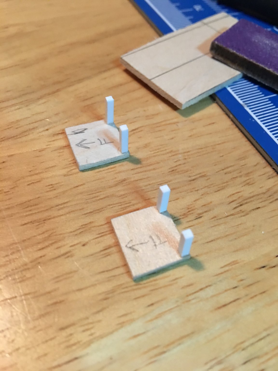
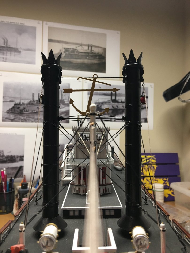
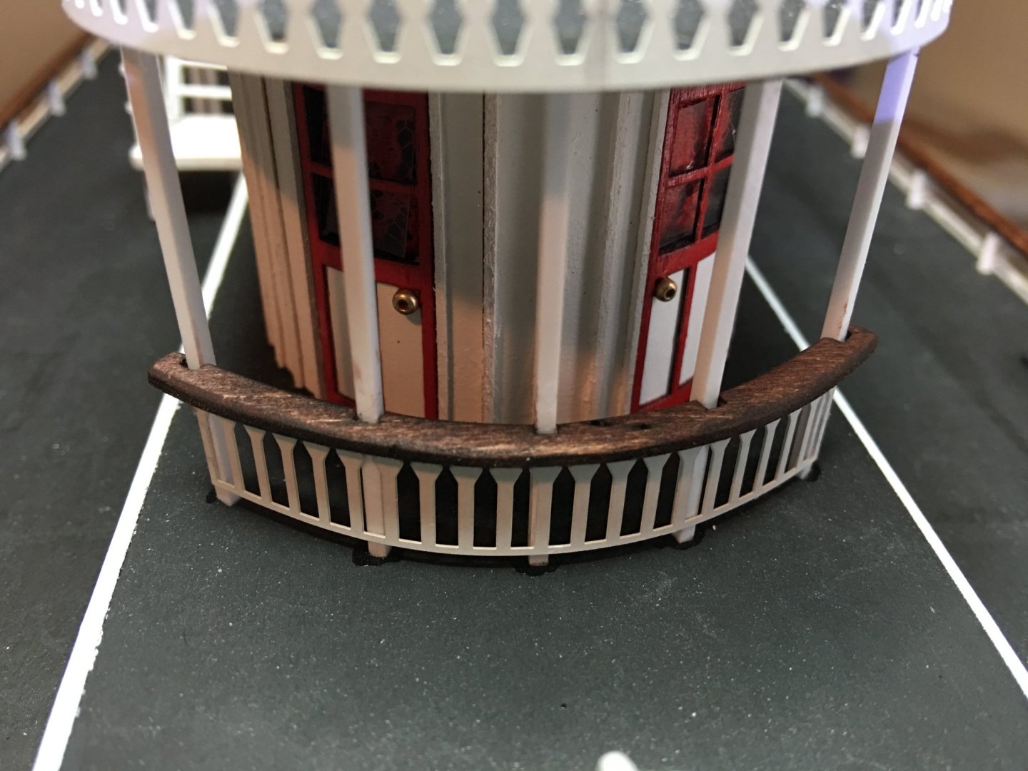
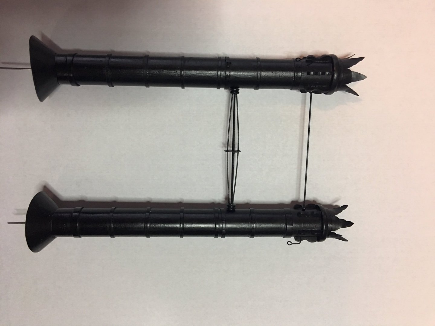
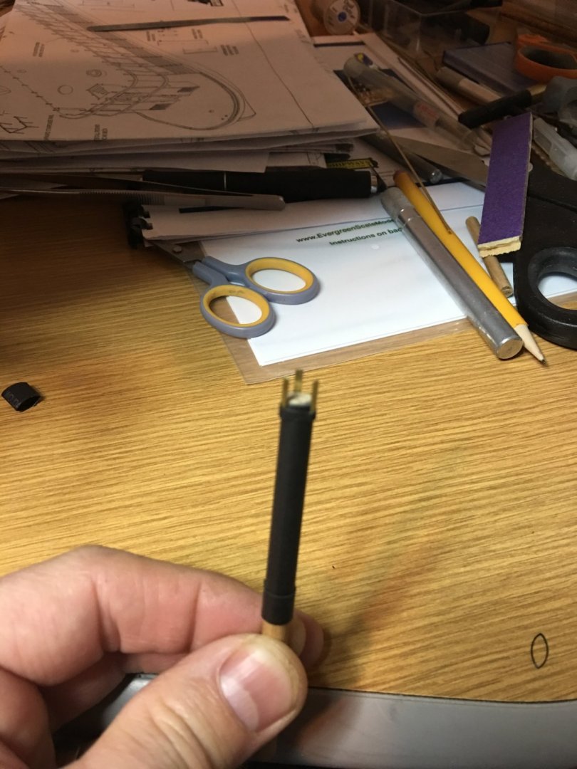
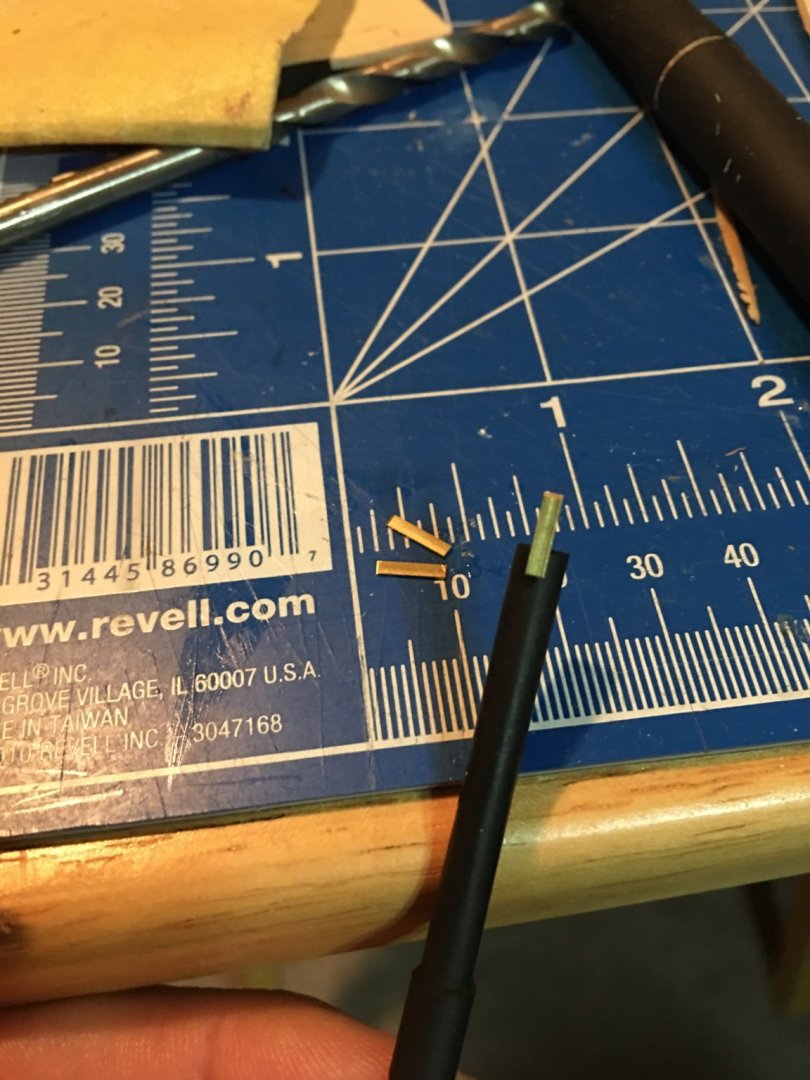
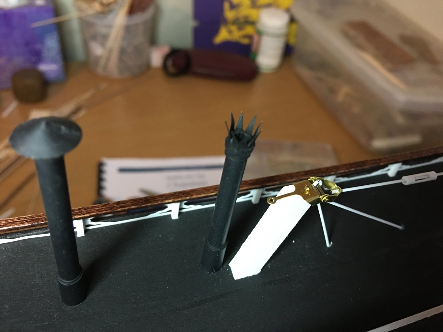
Hello again everyone, I am taking full advantage of being back to work on my build. My two month break gave me great motivation to get things done. This week I was able to complete the hurricane deck railing, the smaller smokestacks and the searchlight platforms. The railing went on pretty smooth, only a couple of adjustments needed to be made. Mainly in the back where the paddle wheel timbers come down and on the front radii. I also added the handrail to the tops of the railing to give it a more finished look. I know the original Chaperon had the hand rails in place, but along with everything, they were painted white. I decided to stain and varnish mine, just to give it a little more contrast. I had a little issue getting the PE railing to take the bend on the front. I am not sure if I didn't get the curvature of the deck right or what, but the thin area between the posts wanted to bulge out when forming the curve. I finally managed to work everything into place by slightly "massaging" the brass causing it to stretch at the top. For the back railing the area behind the paddle wheel timbers was too tight to install the PE so I had to cut it into sections. I stopped the railing on both sides of the timbers and moved the back railing slightly aft to line up with the posts. With the handrail in place, this is hardly noticeable. Next I started work on the smaller smokestacks and chimneys. I wanted to add a little more detail to these, other than just the conical cap that the instructions call for. I made the caps from some thin copper sheeting and added the standoffs made from spare brass flat bar I had and held in place with a dot of CA and some heat shrink tubing. I also added a decorative top to the two chimneys that, according to the instructions, were to just be left uncapped. This was not the case on the actual boat, and old photos show that she had some sort of decorative top on her, although I could not find a clear enough picture of what they actually looked like. I just used a little imaginations and created my own. For these I also used the thin copper sheeting. Lastly, I built the searchlight platforms and installed the. I could not find any pictures of what these actually looked like, so I used the style that Dr. Jens Mittelbach used on his 3D rendering of the Chaperon. Well, that is it for now. More to come. Thank you all for looking as well as the likes and encouragement. -Brian


- 133 replies
-
- 8
-
-
- chaperon
- model shipways
- (and 2 more)
-
Eric, I agree it could be worse. It was just a couple of short years ago when Texas set that record of 42"+ when Hurricane Harvey rolled through Houston, fortunately for us it took a northeastern turn. We moved to Texas about 22 years ago and since that time (with the exception of the occasional hurricane passing over) this was the most rain in a short period of time we have seen come down. We just had the misfortune of the line of storms "train" over us and ring every bit of moisture it could out of the clouds. When I built our driveway, I had thought I had compensated enough for the runoff, since the creek starts on the ranch just west of ours at a pond about a 1000' away, most of the water is shed from the pasture land of our neighbors. The creek bed is only about 3' wide so I installed two 24" culverts thinking it could handle what would come its way. Apparently I miscalculated a tad bit. I should probably stick with model building instead of civil engineering. -Brian
- 133 replies
-
- 1
-
-
- chaperon
- model shipways
- (and 2 more)
-
Eric, Glad to see you back. Interesting method on the tarpaper roofing, I had gone with Kurt's method of silkspan and matte paint on my Chaperon, but I may play round with your pastel method as a comparison for future builds. I definitely agree with testing off the model first though. It saves time and a lot of headaches. My only issue with prior testing is sometimes I get it right the first time (the test piece) and second time around (the actual model) fails to come out the way I wanted it to. On my Chaperon, my test pieces came out almost perfectly (not to toot my own horn), but after testing and applying to my build it didn't come out the same. I had issues with the sides curling up and too much overlap of the "tar seam" (where my glue mixture simulated the tar oozing out between the layers of tarpaper. But as they always say, third times a charm and practice makes perfect. So I sanded it all down and tried again. Worked better that time. -Brian
- 599 replies
-
- 6
-
-
- sidewheeler
- arabia
- (and 4 more)