wrkempson
-
Posts
290 -
Joined
-
Last visited
Content Type
Profiles
Forums
Gallery
Events
Everything posted by wrkempson
-
TurboCad Mac printing line weights?
wrkempson replied to SJSoane's topic in CAD and 3D Modelling/Drafting Plans with Software
I don't have TC Mac and could not reproduce your problem in TC19 for PC. However, the TC forum seems to have a little bit on line widths not printing properly. If I understand the chatter over there, it may have to do with your computer, the printer, default property settings, TC versions, and the tooth fairy. You might try http://tcmacforum.imsisupport.com/ and ask your question there. My experience has been good with the TC community. If all else fails, I have called the company support folks and gotten pretty good response. I know this isn't direct help, but it is what I think I would do next if no one else can come up with an answer on this forum. Wayne -
Well, there's a couple of hours I won't get back; but worth it. It took me a while to realize the two eastern quadrants of the outside curve comprise a semi circle and that for the outside curve the spiral begins at the bottom. The inner spiral begins at the top. How to locate the center of the semi circle took a minute as did the proper way to construct and locate the inner square. I began by looking up how to draw the volute of an Ionic capital (which led me down some false paths) but did get a start on how to back engineer your drawing. Thanks for the challenge. I have no experience with architectural drawings like this, so it was a couple of hours of pure learning. Not bad. My end product looked (to my eye) the same as yours, so no sense posting it. Nonetheless, I guess I qualify as one of the more obsessive among us! Wayne
-
Cad Programs
wrkempson replied to michaelpsutton2's topic in CAD and 3D Modelling/Drafting Plans with Software
I just downloaded Draftsight. Whenever you have a question, like this one, go to Help and type in your query. In this case I simply typed in "insert jpg". The answer was right there. Go to Insert, click on Reference Image, locate the image, etc. I just put a jpg in. Again, all I did was use the Help page in the program. Happy drawing! Wayne -
She is Princess Amelia (80) launched in 1757. Her captain (Macartney) was killed during the battle while his son stood next to him. She was so old and in such poor condition that Parker resigned in protest for having been sent out with her. On the other hand, Princess Amelia served as a flag ship on several occasions subsequent to the battle. The three decker 80's of the 1745 establishments were poor sailors and ill-suited for battle. In the painting, notice the entry port on the middle gun deck; there is no main course bent to the main yard; the ship to the left in the background does not have a topgallant sail bend to the yard but the yard is in the raised position; the sprit yard on Princess Amelia just seems wrongly placed. So, the painting has some accurate details but has other features that might be questioned. Whenever a painting has details you don't understand, see if details you do know are accurate. In this case, the matter might be in doubt. How much protection would hammocks give to the lanyards on the deadeyes? I suspect the answer is: none. Nor would it be needed even for a ship in bad repair since the shrouds being ratted together would have to have most of them cut before the structural function would be compromised. The painting shows similar hammocks on the tops (I think) where they might make sense as barriers to small arms fire (but I can't think that this was done either). In short, this is a baffling rendering. (I conclude she is Princess Amelia since she has three decks, and Princess Amelia was the only 80 present, the next largest ship being 74's.)
-
I set up your AP, FP and Dead Flat heights (the DF 66' aft of the FP) and came up with a radius of 1799' 7 1/2 ". I have no familiarity with SW but can you draw the arc at a smaller scale and then scale the results up to real world dimensions? TurboCAD just now let me draw an arc with a radius of 20,000 miles. Wayne
-
When the plans for Euryalus first came out, I was asked privately if I would supply a set of plans on large sheets, rolled and not folded. I was happy to do so. But by the time I had the plans printed, the mailing tube purchased, the postage paid (and not to mention the time, travel, etc. involved), I had almost as much invested in the new set of plans as the cost of buying another book! I was happy to supply the plans gratis, but at the same time I cannot afford to do so in general. No one who produces one of these works does so for the money, but there are others who rely in some way upon the ongoing sale of the books (i.e., the publisher who fronts all the development funding and takes all the financial risk). I can also say that if one divides the amount of money received from the sale of the books and plans by the number of hours worked the outcome is something under slave wages. I think Ed has given a good review of the question and has offered two reasonable solutions. Wayne
-
Harvey, it sounds like you are encountering all the problems associated with the NMM plans. You are right to press ahead. Good new, though. You won't be using the half breadth lines anyway so it is only for practice. Maybe you can think of it this way. The top of the keel is a straight line of known length which you draw (not trace) on top of the NMM plan. The perpendiculars are at now places and a known distance apart so you draw (not trace) those as well. You have already noticed that a perpendicular on the plan is not, well, perpendicular but is off for the reasons already described regarding the aging of the paper. Now you have the three most important lines from the profile plan. The same thing is done for the body plan for the center, top of keel and breadth lines (none of which are straight or perpendicular on the plan, but you draw them so as best you can). Again, these have known dimensions that you reproduce. At this point you place vertical perpendiculars on top of the station lines on the profile plan as best you can. At this point you have almost all the lines needed for making a set of waterlines. Just add the stem and stern by tracing along with the rabbet, and draw you own waterlines on the profile (but your new lines can be parallel to the keel and uniformly distanced). To the body plan add the traced body lines. From this you make a set of waterlines that may look just awful. But you fair up the water lines. Then you get rid of the original station lines on both the profile and body plan. Place your own set of station lines (more accurately placed) on the profile plan and then use the faired waterlines and the profile station lines to make new body lines. At this point the body lines look a bit off so you fair them as best you can. Now you get rid of the water lines so you can draw up an new set of waterlines that are in harmony with the body lines. These you fair again with the body lines until you are happy with your results. As you can see this is hardly "tracing" the plan anymore. You might try to draw the body lines as per the old draughtsmen, but I think you will find that every bit as disheartening as the above and, at the extremes of the hull, a bit daunting. The suggestion about putting the NMM plan on a separate layer is a good one. This is especially helpful when you stop using the plan and are working only with your own lines. This point comes a lot sooner than most people think. From what you have said, it sounds to me like you are on the right track. Just don't think the NMM plan can be traced all that much. It is very much the guide to drawing, not tracing. Somewhere there may be a bit more information on the process I have tried to describe briefly. I just took a minute to rotate lines in TC v.14 and had no trouble with a rotation of .01 degrees. I'm not sure why you are having a problem with that. Wayne
-
Nope, don't know of a way to stop it. Look at it this way, when you select a drawing tool, it has to be drawn on some layer. So TC assumes you have assigned the layer to the tool that is good for you. It really isn't that much to change the layer assigned to a drawing tool. Objects can have their layer changed pretty easily as well from the drop down menu in the upper left. A locked layer does not prevent a new object being inserted but does block changing an object once it is on the layer. As you learn TC, the help documentation is pretty good. Also, there is a forum http://forums.turbocad.com/ that has some really nice people on it who are always willing to answer questions. Wayne
-
The advice here is guru-esque to be sure. I may add one thing. If I understand the question, it seems that lines drawn on top of an imported photo are covered up when the photo is selected. You might also select the lines in question and then they show up with the photo. When you scale the photo the lines will scale with it, however. But if we are talking about the AP and FP that shouldn't be such a bad thing. Construction lines cannot be selected, but you already know the work around for that. I am flattered whenever anyone reads that little treatise, but at the same time am embarrassed by the things in it that should be edited. So, I ask you to take it as a starting suggestion and not as gospel. I would have removed it a long time ago, but it seems folks are still getting some use out of it. Wayne
-
HMS Euryalus by egen -
wrkempson replied to egen's topic in - Build logs for subjects built 1801 - 1850
Druxey is referring to Ed's log, parts 57 and 79 where these timbers are shown. Wayne -
HMS Euryalus by egen -
wrkempson replied to egen's topic in - Build logs for subjects built 1801 - 1850
We may want to allow ourselves some latitude on the matter of the upper deck transom. The 8 1/2 " dimension of the framing plan is taken from the contract. The size of the transom on the drawing is taken from the original plans. They do not match. The transom on the quarterdeck framing plan is 8" in accordance with the contract but on the original inboard drawing it is 12". My inboard drawing reflects the original inboard drawing and not the contract. All along the way we were faced with this kind of contradictory evidence. There was quite a bit of time between drawing the various components of the ship, so I suspect that is why in this case both sets of dimensions have made their way into the book and plans. Where does that leave the builder? In the same place as Mr. Adams at Bucklers Hard. You will need to fit the piece in. Alan built the model so he is more able to describe his process. The inboard profile gives a larger timber with more room to accept the rabbet for the deck planking. On the other hand, the stern was to be kept light. Ed seems to have chosen the larger figure for Naiad (plan 13D). Anyway, that I think is the genesis of the problem. Wayne -
Your work is a pure delight. Thank you for posting. Wayne
-
Tom, If you bring up the Help menu and click on Help Topics, when that comes up, look through the contents. Especially, I would think that "Inserting Objects" will list out the drawing tools for TC and you should be able to see their similarity to AC. Read through the Help topics for descriptions, explanations and guides. There are some good tutorials available for a price, but a lot of free stuff on YouTube. I learned TC by exploring and reading the Help Topics (well, back then it was a printed manual, but the presentation was the same). Wayne
-
Wayne, I have used TurboCAD for years. The deluxe version in the add you received is sufficient to draw out ship plans. TC is what I used to produce the drawings for Euryalus. TC is a robust program that is priced far, far below other programs. I'm sure the extra two, three, or four thousand dollars is worth it to buy some of the programs mentioned on this thread, especially if you are after 3D model building. TC deluxe can do only a limited amount of 3D work; TC Pro and Platinum can do some pretty impressive stuff, but for ships I don't see them matching the higher priced programs in the 3D arena. Once you decide you are after drawing out 2D plans and not building 3D models, then the problem is simplified greatly. Think about it, prior to computers people were drawing out these things with paper, pencil and a few drawing tools. These are well replicated in TC deluxe. Again, if you are after 3D modeling, TC runs into its limitations after awhile. (Then again, I am an amateur in the CAD world, so there are probably some TC gurus who can run rings around my understanding of TC's capabilities.) Now, TC v20 is just out. I started with v4, then moved in order to v8, v10, v14 and now use v19 Pro. My observation is that you really don't need v20, one of the earlier versions will do. I still go back to v14 sometimes. Look for it on ebay, often the older versions can be had legitimately for a song. Beginning with v19 a 64 bit capability greatly increases the rendering power of TC, so that's something to keep in mind if you want to do 3D at some point. Also, visit the TC forums ( forums.turbocad.com ) and look through the gallery section to see some really good models people have done with TC. As for being a novice, I have no training at all in CAD, designing, engineering, or pastry cooking (I thought I would throw that in). Nonetheless, I had no trouble learning TC. For that matter, knowing TC has given me a basis for dabbling in AutoCAD. I managed to draw out a basic set of lines for Boreas in AC before the 30 days ran out. In short, I answered the TC add years ago and have been very happy and content with TurboCAD. I have played around with the trial versions of AutoCAD and recently with Microstation. I have also dabbled in Alibre and Sketchup. In my limited experience, TC can hold its own in the 2D field and acquits itself very well in the 3D arena as well. Wayne
-
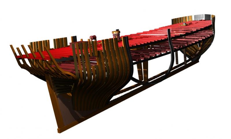
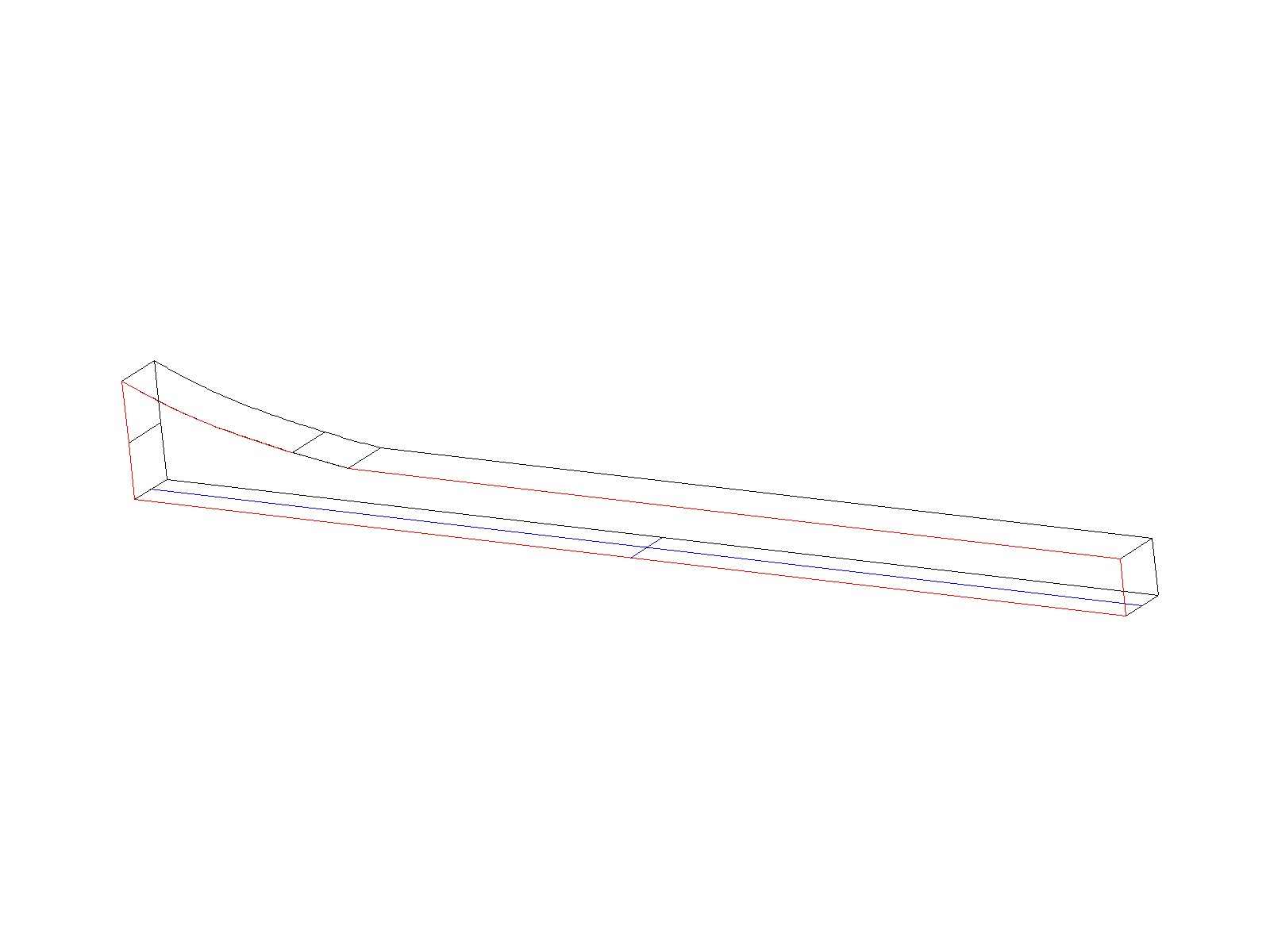
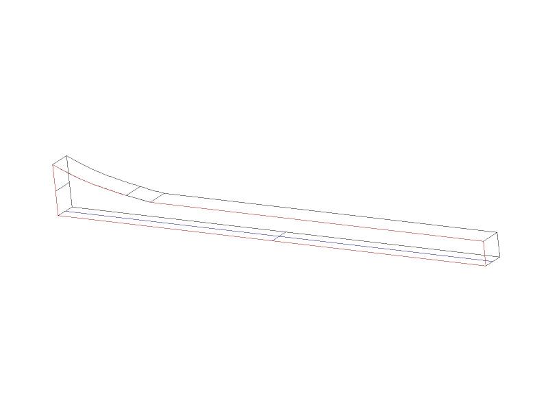
I take it that the 3D is an extrusion of the keel outline. Here I have extruded the first keel timber for Euryalus. The outline is in red, the extrusion is in black. I then make the bottom facet of the extrusion the workplane. Then, using a Middle Snap, I snapped a line to the middle of the forward extruded line and the middle of the after extruded line. This line is in blue. Is this what you are after? Wayne
-
Tony, what is the 3D object? Wayne
-
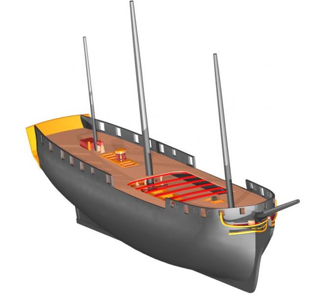
Harvey, as already mentioned TC is not the best program for creating a ship's hull. Mine is the result of a lot of frustration and a number of work arounds. Especially frustrating is the stern. But, if you are going to keep going in TC, I used beziers for the waterlines and then lofted the hull using them. The key is to make sure all the beziers have the same number of nodes. Shelling will be a problem at any rate. There is a very helpful forum for TC users at forums.turbocad.com where this topic has been discussed at length. Just do a search (in the box in the upper right corner) on "hull" and you will find quite a lot. My experience with 3D software is confined to TC (with only a glance at Sketchup and a frustrating trial offer with Alibre and AutoCad). Thus, it really pains me to say TC is limited in this area. It is a very robust program for the money, in my untrained opinion. I think the 3D model with the keel, frames and deck timbers shows that. Tony, keep at it. You just might be the person who makes a simpler hull in TC! Wayne
-
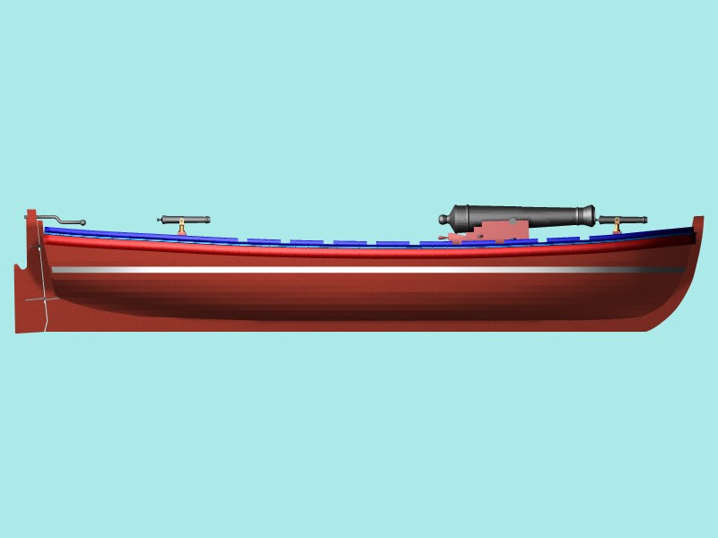
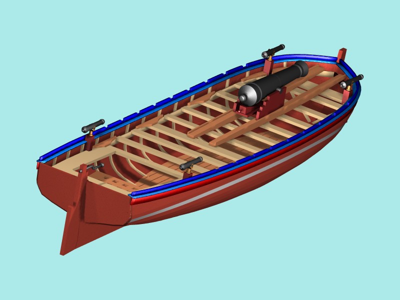
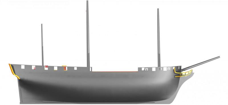
Hi Tony, TurboCAD is not the best software for producing a 3D hull. In Pro there is a lofting function that I have used to create a hull or two from the waterlines, but there is a bit of a problem sometimes due to the logic of the lofting function. This becomes especially problematic when trying to shell the hull. In Deluxe, you can use the prism tool and a close set of waterlines to approximate a smooth hull. Again, TC is not the best tool for creating a hull. Here is a launch I did in Deluxe with the prism tool. You can see the hull is not smooth. And just for fun, here is the hull of Euryalus. You can see some of the limitations that adhere to my skill level and, to a certain extent, to TC. One of the problems you may have with TC is the size of the files. If you are using a 32-bit program (which I think v18 is) then the render times can become quite long. I have been using TC19 Pro 64-bit and the render times are significantly faster. Wayne