HOLIDAY DONATION DRIVE - SUPPORT MSW - DO YOUR PART TO KEEP THIS GREAT FORUM GOING! (89 donations so far out of 49,000 members - C'mon guys!)
×


wrkempson
-
Posts
290 -
Joined
-
Last visited
Content Type
Profiles
Forums
Gallery
Events
Everything posted by wrkempson
-
I use TurboCAD. Concerning the table of offsets, I have never used them. When the actual lofting is done on the floor the offsets are soon abandoned at any rate. Perhaps my efforts will be useful to you. Wayne
-
This is a worthwhile project, but much more challenging than it would seem at first glance. Full speed ahead, Vddoc! You will be finished in two years. Keith, I understand your Tally Ho tally. You could add me to the list, but I never sought to build the boat. I have, however, lofted out the working lines, a set of frames showing the bevel, and lofted out the axial pieces. That exhausted my commitment to the project, so I am done. Here are some screenshots of my work if anyone is interested. This is the plan lines from the internet reworked and reconciled. There are a lot of decisions one must make to fill in missing information on this boat. Tally Ho Master Lines.PDF This picture shows the axial pieces indicating the joinery and frame placements at the heels. Also shown are the lofts of the frames. Drawing1 Frames and Keel.PDF Wayne
-
I have so enjoyed your work on Euryalus these past several years. In every aspect you have produced a masterpiece. Thank you for allowing me to look over your shoulder during this journey. Wayne
-
There is a nice discussion of the bread bin configuration in Euryalus vol 1, p. 111. Your final conclusions (door or lid) will be defensible in either case. I did not find a treatment of the matter in Goodwin. Lavery, p. 189 states that bread was wrapped was not stored in casks, hence I suppose the bins. Perhaps the bread room employed racks. I looked in TFFM but did not find anything in a quick search. Wayne
-
I am enjoying your progress. The level of precision is remarkable. If memory serves, there are three openings aft the capstan labeled "Gra," "tin," and "g" which is to say, "Grating." Also, apertures labeled "Hatch" or the like can have gratings as well. Dashed lines on these openings indicate a shelf in the timber to receive the grating. Well done and inspiring. Thank you for sharing. Wayne
-
I have used the plastic chains and channels. I suspect this is what you mean by the "platform" for the shrouds. I also used the kit's deadeyes and lanyards (the round things with ropes between them). The only part I discarded was the preformed shroud and ratline piece (looks like a triangular ladder). So, using the plastic parts, I set up the shrouds as was done in real practice. The final result was quite pleasing. You have already chosen plastic as the medium for your model, so there is no real requirement that you use wood deadeyes. I have followed this procedure on three of the Revell 1:96 models. They have gone the way of my childhood and are no longer available for photographs. I'm pretty sure eyebolts are not the answer. The choices really come down to setting up wood deadeyes or using the procedure I outline above. I wish you the best as you complete your model. Disclaimer: perhaps I presume too little experience on your part, but your use of terminology tells me you are at the front end of the learning curve for rigging a model.. Wayne
-
Galilee's Rabbet
wrkempson replied to CDR_Ret's topic in Building, Framing, Planking and plating a ships hull and deck
Terry, I think your observations in the original post are entirely correct. I might add that there are some conventions in ship plan drawings that are not to be found in the actual construction of the ship. Rabbet lines are one such convention. The dotted lines on the body plan are indeed indicators of the depth of the rabbet, but the actual lines would be quite fiddly (read: almost impossible) to loft and would be of no value at any rate. On the profile plan the "flat" stretch of the inner rabbet line is not in fact flat; but since it varies from the width of the garboard plank by fractions of an inch there is no good purpose in lofting the actual shape of the line in a basic drawing. I have lofted this line myself and can tell you the amount of curvature is virtually nil (but only virtually, it is real nonetheless) and is possible only in CAD or some such overly precise drawing tool. At any rate, the finally shape of the rabbet must be cut in situ so drawing it with precision is not productive. So, your inner rabbet line ultimately should be lofted on the basis of the how the frame line is finished off at the keel, another process in the drawings that is done more by convention than by geometric accuracy in the older drawings. As you point out, the inner rabbet line derives from the intersection of the frame line (equals the inside face of the planking) and the plane of the side of the keel. I have seen modern drawings where these lines are done accurately. I don't know about the era in question for your ship, but suspect there was still a bit of simplification going on. Now, add to all this the taper of the keel fore and aft and you have quite a donnybrook. I have no conclusions for you in all this, just some observations to agree with your final game plan. Berger's drawing may be neither in error nor mistaken. More likely it simply follows the conventions of the day which the men in the yard would know to adjust during construction. None of what I have to say relates to the shape of the garboard. Finally, the notices made of the DTM plan ring true to my inexpert understanding. It looks like it may have been drawn using accepted conventions and a modicum of guesswork (regarding actual bolt placement, garboard shape, etc.). Usual disclaimers inserted here, Wayne -
I have no knowledge of Spanish practice regarding the rabbet and the keel. I say this to excuse myself from comment only because I would like to be helpful but my knowledge base is restricted to English ships. I do observe, however, that on RN drawings the keel is more of a convention than an actuality. The men in the yard would not use a drawing to cut in the rabbet. So, to answer your question one would have to know the practice of the Spanish yards. All of this is to say: I don't know. Wayne
-
Am I following a good approach, or are there features of Fusion 360 that I have overlooked that would make this easier? I believe your approach is sound and you are not missing some "secret." Programs dedicated to ship hull design handle things pretty well it seems (I have not used one to date), but hulls are fairly challenging for programs like Fusion 360. On the TurboCAD forum a ship's hull is something like the Holy Grail of lofting. How do incorporate the station lines that couldn't be used in the loft + rails? It helps when all the stations have the same number of nodes. I sometimes add a node to account for a missing water line. The key is not so much that the added node is on the same plane as the water line as it is that the computer can loft "node to node" (I just made that phrase up). How do I close up the shape at the bow? Think of the rabbet on the stem as a kind of station line, draw it and loft to it. This will get you in the ball park but is not the total answer. Come to think of it, I'm not sure anyone really knows the total answer. At the gripe a lofting will do some funny things. Of course, added stations at the bow will facilitate things quite a bit. How do I force curved edges of a body like the one below into straight lines that can bend at sharp angles? Your picture illustrates the basic problem of lofting a hull. You can think of the lofting process as akin to the computer connecting your stations with splines (with the fit points falling on the stations). Now, in your illustration the lowest spline (so to speak) takes a downward drift in order to set up for the hard upward turn. Doesn't it look like a driver who swings wide left to then turn right? The closer the stations are to one another the less the swing which is why adding stations can help. The same thing happens at the bow in the area of the gripe. At the rail the problem is evident again, but is more easily fixed by using the rail line to create a loft which is then subtracted from the hull. Now for the necessary disclaimer. I am not trained in CAD nor do I work in the field. The above is the result of my own experience. I remain open to a more perfect way and bow to the expertise of others. Wayne
-
Fusion 360
wrkempson replied to Williamo's topic in CAD and 3D Modelling/Drafting Plans with Software
Mark, I found this and it may solve your problem. My copy of F360 refuses to load for some reason so I can't check it out, but it sounds to me like the answer you need. https://forums.autodesk.com/t5/fusion-360-design-validate/rotating-3d-wood-material-in-render-mode/m-p/7905382#M155048 Wayne -
A work around for TC Deluxe is to put your monogram on the barrel, then create a tube around that section of the barrel that has an inside hole that matches the barrel as to angle but is (say) an inch larger in diameter. Then subtract the tube from the monogram and you will be left with an upper surface of the monogram that is curved with a radius parallel to the barrel. Takes but a minute.
-
Breathtaking. The level of detail is amazing. Congratulations on your work. It seem to me you must have a very large file for this project. Can you give us an insight into how large? What are your render times for the complete model? And, just because of curiosity, what is your computer set up? I would guess you have a pretty good bit of horsepower. Thanks so much for sharing. Wayne
-
See above post #22. Does Solidworks have something called a Style Spline and is that the same thing as a Bezier? I can spell Solidworks and that exhausts my knowledge of the program. I may be confusing you by using the names given to spline tools in TurboCAD. At this point, it seems to me that splines and their control points all use the same equations, but differ in how one manipulates the control points. To be sure, I am not the person to opine here in that my acquaintance with mathematics falls in the interested hobbyist category. There are videos on YouTube that explain Beziers and the history thereof using basic algebra. That and a series of Google searches constitute the foundation of my awareness of the math involved. Wayne
-
internal framing
wrkempson replied to rth385's topic in Building, Framing, Planking and plating a ships hull and deck
I am with Druxey on this. Take a look at this part of EdT's log on the Naiad (a vessel of similar size and construction). This is page two of his log, Find post #57 and begin reading. You will find many helpful photographs of how the internal planking might be done. As a further caveat, Steel says that the limber strake is drawn on the inboard profile plan as a line parallel to the cutting down line (which amounts to the bottom of the keelson). On Steel's plates this line for the limber strake runs the length of the keelson, although as Druxey ponts out it is fairly impossible to place a single plank this entire length and so the channel ends much sooner The original plan from RMG shows the limber strake line the full length of the keelson. I did not build Euryalus. Perhaps Allan can give us some better insight here. Wayne -
You ready for this bit of wisdom? It depends. I used something that TurboCAD calls Beziers which is fit points plus control handles for every point. I have more trouble with the other versions of the spline (by control or by fit points). I find "fit points" easier to use than "control points" and Bezier easiest among the three. So I would say use what makes the most sense to you. I would expect there to be a learning curve on using splines. rtwpsom2 says he prefers the control point splines to Beziers, I have the opposite preference, mostly on the basis of what I am most accustomed to using. I like Beziers but have seen some lines drawn with fit points and control points that were just as good. Use what falls most easily under your mouse. There are folks on this forum who do CAD for a living, and I would greatly appreciate reading their insights on this. My CAD work and knowledge is purely that of the interested amateur. Lately, however, I have been trying to use arcs rather than splines. Sometimes that works out, sometimes it may be more trouble than it's worth. I hope this helps. Wayne
-
I am not a mathematician nor do I play one on TV, but I find the visual explanation of Bezier curves to be quite interesting. The math behind it is barely in my range of comprehension. This link gives a picture of how linear, quadratic, cubic and quartic curves are generated. This is a very amateur understanding, but it takes something of the mystery out of how the spline is drawn and what is happening as it is adjusted. https://www.jasondavies.com/animated-bezier/ Also, the Wikipedia article on Beziers has some interesting animations about two thirds of the way down in the article. https://en.wikipedia.org/wiki/Bézier_curve#Constructing_B.C3.A9zier_curves There are some other basic articles explaining Beziers curves and thus indicating how splines are generated. As far as I can tell, a spline by control points and a Bezier are generated with the same equations. None of this changes how we do things, but I thought it useful to visualize how the computer is doing things. Wayne
-
Good observation, Rick. When you speak of splines are you including Bezier curves in that category? Frankly, while I use Beziers quite often, I cannot think of a time when I have used a traditional spline. The control handles on Beziers make them a very powerful way to create a curve. With that said, and with my completely amateur status noted: The "arc or spline" question might have the age old answer: it depends. For earlier plans arcs reflect the original practice; so if you want to mimic the old ways then an arc is your friend. On the other hand, later plans I suspect made more use of ship's curves for which Beziers are a good substitute (vis-a-vis a collection of tangent arcs). Using arcs is not as well adapted to 3D modeling since they complicate the need for uniform node counts, etc. Beziers, as pointed out, can produce all kinds of accurate curves. There is something satisfying to me in drawing out lines with just arcs and a straight edge. But for actually getting the work done splines (Beziers for me) are great. So, as one who started out using Beziers (splines, if you will), and then learned to use acrs, I suggest we have both in the tool box. Wayne
-
If your program has this tool, construct a circle from three points along the curve of the stem. I would use a portion of the curve that does not intersect the base line since if there is more than the one arc, the second arc will be found at the base line. The center of the circle will of course be the center of the arc. The same end is accomplished geometrically by placing three points on the stem arc. Join the bottom and middle points with a line. Draw a perpendicular line to this line that bisects the line. Repeat the process for the middle and upper points. The intersection of the two bisecting perpendiculars will give you the center of the stem arc. If your heart is pure you will find the artist's pin prick nearby. It may not be useful, however. I have yet to find a table of scantlings helpful in drawing the stem curve. I have always had to find the center myself. By and by, I am thinking we are talking about the arc of the rabbet which often is the after face of the stem. Be careful when then drawing the forward face of the stem since that arc does not necessarily share the same center. The forward face arc center may have to be found separately. Also, the stem arc can be two (as per Druxey) or as many as three arcs. This is known by observation. I don't know if this helps, or even if I am on topic. In my defense I will say I enjoy drawing out the stem arc(s). Of course, the curvature of the cutwater is even more a thing of beauty. Wayne
-
It seems to me that a measurement taken from the plans should trump one taken from elsewhere. A contract measurement might trump the plan but only if the contract is for the specific vessel at hand (ie, not from a sister ship). My observation indicates that the lines on the plans are about 1/4" wide or so, so a variance of 1/2" is understandable in this case. I love the zebra analysis. The curvature of the rabbet in the area of the fore foot seems to be off, but that is due to the program, not your work. Wayne
-
Fusion 360
wrkempson replied to Williamo's topic in CAD and 3D Modelling/Drafting Plans with Software
So I took the Fusion 360 challenge. Having used Turbocad for years, I found F360 to be fairly straight forward. The hardest part is finding the tool you want and learning the peculiarities of the program. I have done some work in Onshape and found it comparable. It seems to me that anyone willing to put in a bit of time, willing to look at training videos and willing to persevere can learn both F360 and Onshape in a reasonably short time frame. The work flow details differ, but not so much as to make difficult the adapting previous of methods to each program. Both Onshape and F360 are free cloud based programs. Onshape's free version is fully functional but limits the number of files one can store to 10. Fusion 360 offers the fully functional version for free to hobbyists. You do have to sign up and indicate that you are either a hobbyist or a start up business. The guidelines for signing up are very clear. I choose to model a 29' Launch in TC and F360 just to compare the two. I was learning F360 from scratch and have done a fair amount or work in TC. The results are appended. Do not get too excited about comparing the renderings since my skills in rendering are quite crude. The point is that each program produces an interesting model. Perhaps I will test out converting the models to 2D drawings at some future date. I should mention that launches were still whole moulded, so there was very little employment of Beziers in these models. This the the Launch from Fusion 360: And the same plan in Turbocad v. 19: Wayne.thumb.jpg.64c0a56694e6882a8329792ddd0def12.jpg)
.thumb.jpg.950a0282bfbb38a9816352e2f2203f14.jpg)
.thumb.jpg.ca5a6bcf577238a5b9ea36d005676c34.jpg)
.thumb.jpg.2326065d486fbbc7097c7ca8c1bb3a67.jpg)
.thumb.jpg.4d2d7e5114731cfd6a8cc444111bd51a.jpg)
.thumb.jpg.f95f854d09f85523541b1a9f08b52a41.jpg)
-
Deck plank detail
wrkempson replied to Srodbro's topic in Building, Framing, Planking and plating a ships hull and deck
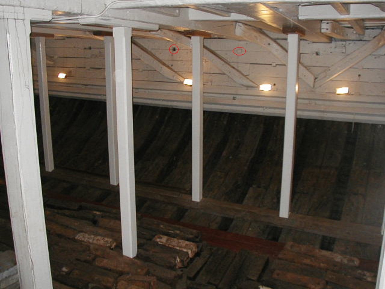
In theory this arrangement keeps the planks for sliding alongside one another resulting in a stiffer longitudinal structure. In the hold of USS Constellation the ceiling planking has square cutouts across the seams into which a square block is inserted in order to stiffen the hull as well. The attached photo shows these openings, some of which have had the blocks fall out. Indicated in red are examples of an empty and a filled opening. Other instances are apparent as well. Wayne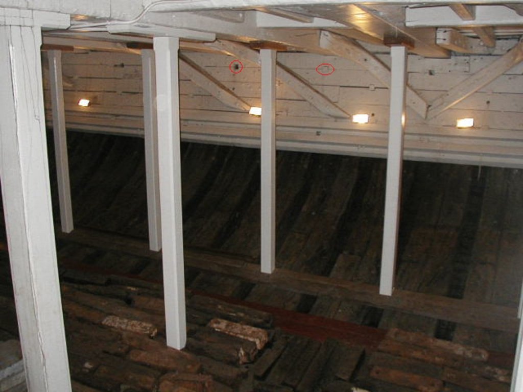
-
TurboCad 2017 Pro allows pdf files to be inserted as underlay objects, more or less as raster images. The resolution is not the greatest but it does allow it. You can also load your pdf in Acrobat, take a screen capture and convert in Paint to a jpg. The resolution is a little better that way. Actually, you may want to search the web with "pdf to jpg" and you will find several apps that convert pdf's to jpg's. I am under the impression that Acrobat Pro has a utility for converting to jpg's. I have no need for such, but they are there for your consideration. Wayne
-
Trying to muscle the errant middle into place sounds like something I would try to do. That should warn you that it may be a questionable move. It seems to me that a buckle in the middle indicates a snying of the ends. This happens to me (all the time when I was laying on the hull planking) due to poor spiling of the plank. Before you apply the force, maybe one more time with a careful spiling might be interesting. I say this as one whose skill falls far below yours, so I offer this more as a question than as advice. Wayne
-
Also for what it is worth, colors do not behave on small models the same way as on full size ships. Here we are getting into the area of scale colors. I would observe that a very light colored ratline on a black (maybe) shroud will pop out to the eye on the model. An even worse mistake that I have committed is to use a line that is too large. The scale size of the ratline should not be exceeded, but may be lessened if anything. When I look at photos of full rigged ships, the ratlines are barely visible unless one makes the effort to see them. I don't think the ratline should call attention to itself. As always, the usual disclaimer. Wayne
-
Knighthead
wrkempson replied to brobertson's topic in Building, Framing, Planking and plating a ships hull and deck
I presume you are building the Model Shipways kit. If so, I found the manual at http://modelexpo-online.com/assets/images/documents/MS2018-Flying_Fish-Instructions-Complete.pdf . On page 24 Figure 36B there is a good illustration. The knightheads are the two timbers on either side of the opening for the bowsprit and each one receives an eyebolt. The Figure gives a profile and top view of the piece you are asked to make. The exact shape will be determined by your own model so the process is to cut and fit, sand, fit, shape again, fit, etc. until the timbers are in place. I do not have the plans, but the manual points you in the right direction. On the actual vessel, the knightheads extend from the rail level down along the side of the stem to a place well below the water line. On your model they are represented with only the visible portion above the deck. When you install them make sure they are secure as they will have quite a bit of strain on them from the fore stay that attaches to the eyebolts. It is unclear to me what your exact question might be, but maybe the above helps. Wayne

.jpg.92160547a31909dcb8b5feffcd3a1c23.jpg)
.jpg.d6b8c1b142c61ab0458c50094a7b39bd.jpg)
.jpg.092757b33efd0056585ac93fce3be00e.jpg)
.jpg.c25f964f12351892c846b26c5528943d.jpg)
.jpg.46f2a7464397c8114b7bdb3a46e957fb.jpg)
.jpg.4b57e7aec35cc0b478b20510797117c7.jpg)