


wrkempson
-
Posts
288 -
Joined
-
Last visited
Reputation Activity
-

 wrkempson got a reaction from BANYAN in H.M.S. Atalanta - Drafting my own plans
I am not a mathematician nor do I play one on TV, but I find the visual explanation of Bezier curves to be quite interesting. The math behind it is barely in my range of comprehension. This link gives a picture of how linear, quadratic, cubic and quartic curves are generated. This is a very amateur understanding, but it takes something of the mystery out of how the spline is drawn and what is happening as it is adjusted.
https://www.jasondavies.com/animated-bezier/
Also, the Wikipedia article on Beziers has some interesting animations about two thirds of the way down in the article.
https://en.wikipedia.org/wiki/Bézier_curve#Constructing_B.C3.A9zier_curves
There are some other basic articles explaining Beziers curves and thus indicating how splines are generated. As far as I can tell, a spline by control points and a Bezier are generated with the same equations. None of this changes how we do things, but I thought it useful to visualize how the computer is doing things.
Wayne
-
 wrkempson got a reaction from Bob Legge in H.M.S. Atalanta - Drafting my own plans
I am not a mathematician nor do I play one on TV, but I find the visual explanation of Bezier curves to be quite interesting. The math behind it is barely in my range of comprehension. This link gives a picture of how linear, quadratic, cubic and quartic curves are generated. This is a very amateur understanding, but it takes something of the mystery out of how the spline is drawn and what is happening as it is adjusted.
https://www.jasondavies.com/animated-bezier/
Also, the Wikipedia article on Beziers has some interesting animations about two thirds of the way down in the article.
https://en.wikipedia.org/wiki/Bézier_curve#Constructing_B.C3.A9zier_curves
There are some other basic articles explaining Beziers curves and thus indicating how splines are generated. As far as I can tell, a spline by control points and a Bezier are generated with the same equations. None of this changes how we do things, but I thought it useful to visualize how the computer is doing things.
Wayne
-
wrkempson reacted to Ben752 in H.M.S. Atalanta - Drafting my own plans
One of the limitations of fusion is that the spline support is far from great compared to others out there. They should be launching proper CV curves within the next year or so. They have recently published a post showing some of the upcoming capability, which should put them more inline with that of solidworks.
-
 wrkempson got a reaction from trippwj in Extreme Clipper Witch of the Wave CAD
Both the drawing and your procedures are works of art. Thanks for sharing.
I did not understand how the offset of the splines was used to center the traced working line. This may be because I do not have access to Solidworks. Still, I couldn't get my head around the theory of it, but it sounds like a useful thing to know in general (unless this is Solidworks specific).
It seems you have a very good original plan. Even at that, I take it you did a bit of work to straighten some lines out prior to use in CAD. I find all this very interesting. The tools available to you for curvature analysis are fascinating. In TurboCAD I rotate the drawing and eyeball down the line, a method similar to the actual method on the lofting floor. I like the more accurate tools in Solidworks. I believe similar tools are available in Fusion 360 and Onshape.
This looks to be a very interesting project.
Wayne
-
wrkempson got a reaction from BANYAN in Extreme Clipper Witch of the Wave CAD
Both the drawing and your procedures are works of art. Thanks for sharing.
I did not understand how the offset of the splines was used to center the traced working line. This may be because I do not have access to Solidworks. Still, I couldn't get my head around the theory of it, but it sounds like a useful thing to know in general (unless this is Solidworks specific).
It seems you have a very good original plan. Even at that, I take it you did a bit of work to straighten some lines out prior to use in CAD. I find all this very interesting. The tools available to you for curvature analysis are fascinating. In TurboCAD I rotate the drawing and eyeball down the line, a method similar to the actual method on the lofting floor. I like the more accurate tools in Solidworks. I believe similar tools are available in Fusion 360 and Onshape.
This looks to be a very interesting project.
Wayne
-
 wrkempson got a reaction from thibaultron in Extreme Clipper Witch of the Wave CAD
Both the drawing and your procedures are works of art. Thanks for sharing.
I did not understand how the offset of the splines was used to center the traced working line. This may be because I do not have access to Solidworks. Still, I couldn't get my head around the theory of it, but it sounds like a useful thing to know in general (unless this is Solidworks specific).
It seems you have a very good original plan. Even at that, I take it you did a bit of work to straighten some lines out prior to use in CAD. I find all this very interesting. The tools available to you for curvature analysis are fascinating. In TurboCAD I rotate the drawing and eyeball down the line, a method similar to the actual method on the lofting floor. I like the more accurate tools in Solidworks. I believe similar tools are available in Fusion 360 and Onshape.
This looks to be a very interesting project.
Wayne
-
 wrkempson got a reaction from AntonyUK in Fusion 360
So I took the Fusion 360 challenge. Having used Turbocad for years, I found F360 to be fairly straight forward. The hardest part is finding the tool you want and learning the peculiarities of the program. I have done some work in Onshape and found it comparable. It seems to me that anyone willing to put in a bit of time, willing to look at training videos and willing to persevere can learn both F360 and Onshape in a reasonably short time frame. The work flow details differ, but not so much as to make difficult the adapting previous of methods to each program.
Both Onshape and F360 are free cloud based programs. Onshape's free version is fully functional but limits the number of files one can store to 10. Fusion 360 offers the fully functional version for free to hobbyists. You do have to sign up and indicate that you are either a hobbyist or a start up business. The guidelines for signing up are very clear.
I choose to model a 29' Launch in TC and F360 just to compare the two. I was learning F360 from scratch and have done a fair amount or work in TC. The results are appended. Do not get too excited about comparing the renderings since my skills in rendering are quite crude. The point is that each program produces an interesting model. Perhaps I will test out converting the models to 2D drawings at some future date. I should mention that launches were still whole moulded, so there was very little employment of Beziers in these models.
This the the Launch from Fusion 360:
And the same plan in Turbocad v. 19:
Wayne
-
 wrkempson got a reaction from rtwpsom2 in Extreme Clipper Witch of the Wave CAD
Both the drawing and your procedures are works of art. Thanks for sharing.
I did not understand how the offset of the splines was used to center the traced working line. This may be because I do not have access to Solidworks. Still, I couldn't get my head around the theory of it, but it sounds like a useful thing to know in general (unless this is Solidworks specific).
It seems you have a very good original plan. Even at that, I take it you did a bit of work to straighten some lines out prior to use in CAD. I find all this very interesting. The tools available to you for curvature analysis are fascinating. In TurboCAD I rotate the drawing and eyeball down the line, a method similar to the actual method on the lofting floor. I like the more accurate tools in Solidworks. I believe similar tools are available in Fusion 360 and Onshape.
This looks to be a very interesting project.
Wayne
-
wrkempson reacted to rtwpsom2 in Extreme Clipper Witch of the Wave CAD
Started work on a new project, the extreme clipper Witch of the Wave, built in 1851. She was designed and built by George Reynes of Portsmouth, NH. She was originally owned by Glidden & Williams of Boston. Oddly enough, Gerorge Reynes son George Jr also built a packet freighter by the same name in 1856 in the same yard his father built this one in, so there is the possibility to get confused.
Witch of the Wave was quite long lived for an extreme clipper, sailing for at least 34 years. She set only one record, her 1855 passage from Calcutta, India to Boston, MA in 102 days. She was quite beautiful even by standards of the day. A great deal of attention had been paid to the details of her workmanship and the quality of her fittings. Her cabins were fitted out with rare woods of curious workmanship and expensive furnishings. She had a library of over 100 books. Her figurehead was that of a beautiful woman holding aloft a scarf as she glides across the waves, with gilded branches and leaves stretching out behind her that grow to wrap around the hawse holes. She also had occuli, painted eyes on each side of her bowspirit commonly found on ships involved in the tea trade.
This log isn't intended to be anything but a log of how I do stuff. Others do stuff differently and use different tools and concepts to do them. I'm not saying they aren't right, or that my ideas are better than theirs. I'm only trying to show how I go about it. I've worked in SolidWorks professionally since about 2006 and have done some WWII era warship models for Dragon Models and some CAD models of airframes for a company that restores WWII era fighter aircraft. So I'm posting this with the idea that you guys might be interested in how I do things. The quid pro quo is that I am hoping you guys can share your knowledge about ships where I am lacking, and I have been able to ask a few things in the forum already, for which I'm grateful. That said, I am hoping this doesn't come across as me being stuck up about how I do things or that I feel superior to others in my skills and knowledge-base. I do things my way and steal ideas from everyone else when I don't know how to do something. You might notice that EdT's work on Young America is something I consider highly influential.
This is where I started, research-wise. This was the first hard data I found on WotW. It comes from The Search for Speed Under Sail; 1700-1855 by Howard I. Chappelle. The book is 10" tall x 8" wide so unfolded this layout was 10" x 16", a pretty decent size to work with for a scan. Fortunately I happen to have a large format flatbed scanner which can do 11" x 17" at 12,000 DPI.
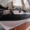
The resulting image was 18528 x 12408 pixels. I cropped a part of it here for you to imagine how large the full size image (zoom for effect). Needless to say it would be a little unwieldy in this format so I had some work to do on it. Here you see the occuli and her figurehead.
The first problem is that the plan and profile images were split on two pages. Fortunately the image didn't go down into the gutter of the spine so I had nice clean edges to work with. In Photoshop I cut out pieces of the image and pasted them into a new document. I then lined them up using the grid and rotate layer command. Here is the profile image done. The processes I'm describing were done for all images, I'm just showing a couple quick reference images in order to save time and space. This is apretty lengthy process by itself and should probably have it's own discussion.
The next part was a little more involved. There was minor warping all over the image. Fortunately there were tons of grid lines that I knew should be straight. I had to use the warp transform tool on the parts to get them into some semblance of straight and true lines. Needless to say this wasn't easy and took me about an hour for each view. The fore/aft view wasn't as hard because I didn't have to stitch two halves together, but it still got straightened up. Here is the plan view done.
Next I used the sketch picture tool under sketch tools in SolidWorks to insert the resulting images into a new part. I added relevant geometry and used the dimensions I knew to scale the image up to the proper size. I found out that the frame stations were on 32" centers which did not diminish near the ends. I then added in more geometry for the individual frame stations.
Next I created a new sketch on the midship plane and added the hull lines and some waterline geometry.
And after that the plan view with buttock lines.
The resulting work in 3D.
Next I added in some rudimentary sketches for the bowspirit and jib boom. This gave me a rough overall length of 273' to 274'.
The next thing I wanted to focus on was the fact that I didn't have a midship cross section to work with, only small sections of individual parts like the keelsons and garboard. A midship cross section is important, as it will help you lay out geometry and understand the interactions of the pieces more easily. So I created this one to get a general idea of how she laid out. Here you can see her rather unique keelson setup. Her sister keelsons were fayed to the floor and transitioned into her 4.5" floor ceilings.
Next was adding planes for each frame station. I accidentally named the first plane m when it should have been l but I fixed that later on.
The garboard is 7" thick at midships but thins out to 4" at the stem and stern. The frame angle varies from about 86º at the stem to 18.5º at midships, then back to 87º at the stern. After doing some number crunching I came up with a rabbet line, shown here in blue. In this view we are looking down the centerline of the ship from just above the baseline so you can see how it warps.
And then I added a bearding line for the keel, again highlighted in blue. Here we are on the horizontal baseline of the keel, looking at it from just right of centerline. If the above rabbet line is the warp, this curve would be the weft.
SolidWorks finds it easier to loft a surface if you maintain some uniformity to it's geometry. I intend to do this in one surface if I can, so I am making each frame loft section full height. It might make more sense once I'm done. Trust me, I'm a professional.
Here I've finished adding in the port side lines. As before, all lines go from the baseline up to the 36' line. These line remain unsmoothed as yet. I will start smoothing them once all the lines are drawn.
Looking from an isometric viewpoint, you can see where the bottom edge of the lines are constrained to the rabbet line (red arrows). That will give us a good start for smoothing later. The blue arrow indicates a good example of how the lines are not smooth yet. Even a well controlled spline won't always do exactly what you told it to and takes some coaxing.
Aft of midships, I run into the rather small problem of having to draw lines on the starboard side of the ship. The solution is rather easy, a simple mirror command, which necessitates we also add a centerline.
Work on the lines nears completion.
Added in a rough estimate of the transom, this is probably not final. The green color is an approximation of the color of Zinc Chromate, the paint used on the insides of aircraft during WWII to curb corrosion. The parts template I use for work has this color as standard, so just ignore it. Or don't, you're an adult, you can do what you want.
Added in planes to add in sketches for the buttock lines. I noticed that when I put the scan in for the reference image I forgot to scale it horizontally. The blue plane lines should line up with the tick marks on the scan. When you scan a drawing to put into CAD like this you need to scale it not only vertically but horizontally as well, and make sure the two are not linked. Line drawings scanned from books are never scaled perfectly one to one in both axis.
Here is the first buttock line. I added in a spline with the same number of control points as there were frames. I then selected a control point and one of the frame lines and used the pierce constraint. The control point of the spline is now connected to the frame line as if it "pierces" through the control point. This let's us compare the model shape against the drawn buttocks lines. The closer I can get the buttock lines to match the lines in the scan, the more accurate the hull will be.
The second line is added and what I am seeing is that the frame lines and buttock lines from the scan are pretty good so far.
Once all the buttock lines are in you can see that me not scaling the lines horizontally is probably causing some issues, since the gap gets worse the further out from centerline you get. I'm probably going to have to adjust the horizontal scale of that front view image again and redo all the frame lines.
Just to check, I moved the planes I created outwards until they lined up with the wrongly scaled front view to see how the change would affect the buttock lines and the result says, "Yep, you're gonna have to fix em."
I added the 39' 8" width in as a couple of reference lines mirrored across the centerline. Then I edited the picture to scale it properly. Remember to uncheck the item in the red box to ensure it doesn't just scale the whole image.
Here's something I do a lot when I am tracing images for a loft. I offset the spline by just larger than than the scanned line is. In this case the line I scanned is scaling out to around 3/4" thick so I offset at 1/2 inch in each direction (bi-directional) and check the offset geometry under construction to make the outside lines into construction or reference lines.
Here's a close up of the result, you can see how it is helpful to get right down the centerline.
Since I know the lines in the drawings I scanned are pretty good, I am going to start the smoothing process. This starts by selecting the main spline and selecting "Show Curvature" in the properties manager. You get a series of lines called a Curvature Comb that you can use to check your spline. You want a smooth comb without these kinks in it when you're done.
Next is to add dimensions to control points. These are already constrained vertically so the only way they can move is horizontally. Controlling them with numbers is the easiest way for me to smooth the curve. Here you can see we have a couple of bad spots but overall it's not terrible.
Sometimes the result isn't a beautiful comb where it is exactly the same thickness throughout, in this case I'm working on frame Y which is in the transition area between the concave curve at the prow and the convex curve amidships. That little dent about 2/3rds of the way up is the remnants of the prow's concavity.
Usually you prefer to see something line frame g, which is straighter as it approaches the bow and begins to curve in a more uniform manner the higher you go.
Smoothing is coming along, but is really tedious so to distract myself I have added some details to midship section. Lower planking was 4" x 14" up to the turn of the bilge. Turn of the bilge is a rather arbitrary term so I put the change where I thought it should be. From there to her plank sheer the planking was 5.5" x 7". The width of the wales planks is only 7 inches, compared to the 14 inches of the the lower planks, this is because the curve becomes more pronounced and the 14" planks are too wide to accommodate the curve. I might still pull out a couple of those lower planks and move the wales down and in a little more, I haven't decided yet, but the curve looks a little to much for those last two.
Her plank sheer is 5 inches think and her main rail is 5.5" x 20". Nothing else is dimensioned so the rest of this is best guess to get the known dimensions to agree with each other. Her bulwark planking is 3" x 6" and only on the outside of the hull. Inside her bulwarks are open up to the rack rail. She has 4" thick clamps above and below the main rail, these fill the gap between the main rail and the monkey rail (fancy rail). I'm not sure about the waterway, in the description by Bruzelius they are said to be 14" square but this seems a bit excessive. They would end up cutting away a quarter of the material when they cut the molding into it. It also doesn't leave a great deal of open space between the plank sheer and the rack rail, but that seems to be an aesthetic thing to me so I'm not sure if that's more than just my opinion.
The next question I need to clear up is the masts location and rake angle. Most of my work is based on the Chappelle drawings, so I kind of default to his being right most of the time, but here I have to disagree with him. Bruzelius describes the rake angles of the masts in inches to the foot, while Chappelle drew them in angular degrees. In other words, Bruzlius says the fore mast is 1.25 inches rake to the foot. If you draw a triangle with one side 12 inches and the other 1.25 inches, you get a rake angle of 5.95º. Chappelle has drawn his masts at 1.25º directly. In my drawing each mast has two lines. The solid line represents the rake angle in inches per foot and the dashed line in degrees. I think we can agree that Chappelle made the common mistake of replacing triangular dimensions with angular dimensions.
The second question is location and here I think Chappelle might be right but I'm not sure. Bruzelius describes the ship as being 202 feet between perpendiculars, but Chappelle describes it as 204'. The reason for the discrepancy is the length between the frames. The original waterlines, when scaled to 204' show a spacing between frames of 32". But at 202' the gap is 31.9". a gap of 31.9 inches seems implausible, so 204' is the more likely length between perpendiculars.
Bruzelius' dimensions for the mast locations are 45' from front perpendicular to the fore, 67' from fore to main, and 53' from main to mizzen, with 37 remaining between mizzen and aft perpendicular. Chappelle, however has the given dims as 45', 68', 53'6", and 37'6". These numbers are in better keeping with the ratio numbers listed in Crother's Clipper book. The below drawing shows the masts located according to Bruzelius. The image below that has them located according to Chappelle.
These changes, overall, will make a little more room at the front of the main deck, but are going to make the poop deck a bit more cramped.
So, overall, this is where work has progressed to after about a weeks work. If you guys see any errors, please let me know, I'd rather fix them now than find them later on.
-
wrkempson got a reaction from Bob Legge in H.M.S. Atalanta - Drafting my own plans
Good observation, Rick. When you speak of splines are you including Bezier curves in that category? Frankly, while I use Beziers quite often, I cannot think of a time when I have used a traditional spline. The control handles on Beziers make them a very powerful way to create a curve. With that said, and with my completely amateur status noted:
The "arc or spline" question might have the age old answer: it depends. For earlier plans arcs reflect the original practice; so if you want to mimic the old ways then an arc is your friend. On the other hand, later plans I suspect made more use of ship's curves for which Beziers are a good substitute (vis-a-vis a collection of tangent arcs). Using arcs is not as well adapted to 3D modeling since they complicate the need for uniform node counts, etc. Beziers, as pointed out, can produce all kinds of accurate curves.
There is something satisfying to me in drawing out lines with just arcs and a straight edge. But for actually getting the work done splines (Beziers for me) are great.
So, as one who started out using Beziers (splines, if you will), and then learned to use acrs, I suggest we have both in the tool box.
Wayne
-
 wrkempson got a reaction from Ben752 in H.M.S. Atalanta - Drafting my own plans
If your program has this tool, construct a circle from three points along the curve of the stem. I would use a portion of the curve that does not intersect the base line since if there is more than the one arc, the second arc will be found at the base line. The center of the circle will of course be the center of the arc. The same end is accomplished geometrically by placing three points on the stem arc. Join the bottom and middle points with a line. Draw a perpendicular line to this line that bisects the line. Repeat the process for the middle and upper points. The intersection of the two bisecting perpendiculars will give you the center of the stem arc. If your heart is pure you will find the artist's pin prick nearby. It may not be useful, however.
I have yet to find a table of scantlings helpful in drawing the stem curve. I have always had to find the center myself. By and by, I am thinking we are talking about the arc of the rabbet which often is the after face of the stem. Be careful when then drawing the forward face of the stem since that arc does not necessarily share the same center. The forward face arc center may have to be found separately.
Also, the stem arc can be two (as per Druxey) or as many as three arcs. This is known by observation.
I don't know if this helps, or even if I am on topic. In my defense I will say I enjoy drawing out the stem arc(s). Of course, the curvature of the cutwater is even more a thing of beauty.
Wayne
-
wrkempson got a reaction from Ben752 in H.M.S. Atalanta - Drafting my own plans
Good observation, Rick. When you speak of splines are you including Bezier curves in that category? Frankly, while I use Beziers quite often, I cannot think of a time when I have used a traditional spline. The control handles on Beziers make them a very powerful way to create a curve. With that said, and with my completely amateur status noted:
The "arc or spline" question might have the age old answer: it depends. For earlier plans arcs reflect the original practice; so if you want to mimic the old ways then an arc is your friend. On the other hand, later plans I suspect made more use of ship's curves for which Beziers are a good substitute (vis-a-vis a collection of tangent arcs). Using arcs is not as well adapted to 3D modeling since they complicate the need for uniform node counts, etc. Beziers, as pointed out, can produce all kinds of accurate curves.
There is something satisfying to me in drawing out lines with just arcs and a straight edge. But for actually getting the work done splines (Beziers for me) are great.
So, as one who started out using Beziers (splines, if you will), and then learned to use acrs, I suggest we have both in the tool box.
Wayne
-
 wrkempson got a reaction from druxey in H.M.S. Atalanta - Drafting my own plans
Good observation, Rick. When you speak of splines are you including Bezier curves in that category? Frankly, while I use Beziers quite often, I cannot think of a time when I have used a traditional spline. The control handles on Beziers make them a very powerful way to create a curve. With that said, and with my completely amateur status noted:
The "arc or spline" question might have the age old answer: it depends. For earlier plans arcs reflect the original practice; so if you want to mimic the old ways then an arc is your friend. On the other hand, later plans I suspect made more use of ship's curves for which Beziers are a good substitute (vis-a-vis a collection of tangent arcs). Using arcs is not as well adapted to 3D modeling since they complicate the need for uniform node counts, etc. Beziers, as pointed out, can produce all kinds of accurate curves.
There is something satisfying to me in drawing out lines with just arcs and a straight edge. But for actually getting the work done splines (Beziers for me) are great.
So, as one who started out using Beziers (splines, if you will), and then learned to use acrs, I suggest we have both in the tool box.
Wayne
-
 wrkempson got a reaction from iosto in HMS Atalanta 1775 by tlevine - FINISHED - 1:48 scale - from TFFM plans
To wit: below is the forecastle of a 70 gun ship c. 1715
-
wrkempson reacted to rshousha in H.M.S. Atalanta - Drafting my own plans
As a daily user of Solidworks, I would like to encourage you to go back and give the splines a second chance. It takes a while to figure out how they work but, once you get a handle on them, you will be much happier than using arcs.
Rick
-
 wrkempson got a reaction from Jack H in H.M.S. Atalanta - Drafting my own plans
If your program has this tool, construct a circle from three points along the curve of the stem. I would use a portion of the curve that does not intersect the base line since if there is more than the one arc, the second arc will be found at the base line. The center of the circle will of course be the center of the arc. The same end is accomplished geometrically by placing three points on the stem arc. Join the bottom and middle points with a line. Draw a perpendicular line to this line that bisects the line. Repeat the process for the middle and upper points. The intersection of the two bisecting perpendiculars will give you the center of the stem arc. If your heart is pure you will find the artist's pin prick nearby. It may not be useful, however.
I have yet to find a table of scantlings helpful in drawing the stem curve. I have always had to find the center myself. By and by, I am thinking we are talking about the arc of the rabbet which often is the after face of the stem. Be careful when then drawing the forward face of the stem since that arc does not necessarily share the same center. The forward face arc center may have to be found separately.
Also, the stem arc can be two (as per Druxey) or as many as three arcs. This is known by observation.
I don't know if this helps, or even if I am on topic. In my defense I will say I enjoy drawing out the stem arc(s). Of course, the curvature of the cutwater is even more a thing of beauty.
Wayne
-
wrkempson got a reaction from druxey in H.M.S. Atalanta - Drafting my own plans
If your program has this tool, construct a circle from three points along the curve of the stem. I would use a portion of the curve that does not intersect the base line since if there is more than the one arc, the second arc will be found at the base line. The center of the circle will of course be the center of the arc. The same end is accomplished geometrically by placing three points on the stem arc. Join the bottom and middle points with a line. Draw a perpendicular line to this line that bisects the line. Repeat the process for the middle and upper points. The intersection of the two bisecting perpendiculars will give you the center of the stem arc. If your heart is pure you will find the artist's pin prick nearby. It may not be useful, however.
I have yet to find a table of scantlings helpful in drawing the stem curve. I have always had to find the center myself. By and by, I am thinking we are talking about the arc of the rabbet which often is the after face of the stem. Be careful when then drawing the forward face of the stem since that arc does not necessarily share the same center. The forward face arc center may have to be found separately.
Also, the stem arc can be two (as per Druxey) or as many as three arcs. This is known by observation.
I don't know if this helps, or even if I am on topic. In my defense I will say I enjoy drawing out the stem arc(s). Of course, the curvature of the cutwater is even more a thing of beauty.
Wayne
-
 wrkempson got a reaction from mtaylor in H.M.S. Atalanta - Drafting my own plans
If your program has this tool, construct a circle from three points along the curve of the stem. I would use a portion of the curve that does not intersect the base line since if there is more than the one arc, the second arc will be found at the base line. The center of the circle will of course be the center of the arc. The same end is accomplished geometrically by placing three points on the stem arc. Join the bottom and middle points with a line. Draw a perpendicular line to this line that bisects the line. Repeat the process for the middle and upper points. The intersection of the two bisecting perpendiculars will give you the center of the stem arc. If your heart is pure you will find the artist's pin prick nearby. It may not be useful, however.
I have yet to find a table of scantlings helpful in drawing the stem curve. I have always had to find the center myself. By and by, I am thinking we are talking about the arc of the rabbet which often is the after face of the stem. Be careful when then drawing the forward face of the stem since that arc does not necessarily share the same center. The forward face arc center may have to be found separately.
Also, the stem arc can be two (as per Druxey) or as many as three arcs. This is known by observation.
I don't know if this helps, or even if I am on topic. In my defense I will say I enjoy drawing out the stem arc(s). Of course, the curvature of the cutwater is even more a thing of beauty.
Wayne
-
wrkempson reacted to druxey in H.M.S. Atalanta - Drafting my own plans
Sometimes the stem curve is made of two different radii, which complicates things! If you are lucky, you can see the prick-mark left by the draftsman's compass when he drew the arcs for the stem and rabbet. Take a line vertically up from the point where the straight part of the rabbet begins to curve and look carefully.
The other method is to make an arc of the specified radius (13' 7 1/2" in your example) and put the center at different points along the curve and strike several arcs. The intersection of those arcs will locate the center of the curve.
-
wrkempson got a reaction from druxey in H.M.S. Atalanta - Drafting my own plans
It seems to me that a measurement taken from the plans should trump one taken from elsewhere. A contract measurement might trump the plan but only if the contract is for the specific vessel at hand (ie, not from a sister ship). My observation indicates that the lines on the plans are about 1/4" wide or so, so a variance of 1/2" is understandable in this case.
I love the zebra analysis. The curvature of the rabbet in the area of the fore foot seems to be off, but that is due to the program, not your work.
Wayne
-
wrkempson got a reaction from mtaylor in H.M.S. Atalanta - Drafting my own plans
It seems to me that a measurement taken from the plans should trump one taken from elsewhere. A contract measurement might trump the plan but only if the contract is for the specific vessel at hand (ie, not from a sister ship). My observation indicates that the lines on the plans are about 1/4" wide or so, so a variance of 1/2" is understandable in this case.
I love the zebra analysis. The curvature of the rabbet in the area of the fore foot seems to be off, but that is due to the program, not your work.
Wayne
-
wrkempson got a reaction from Ben752 in H.M.S. Atalanta - Drafting my own plans
It seems to me that a measurement taken from the plans should trump one taken from elsewhere. A contract measurement might trump the plan but only if the contract is for the specific vessel at hand (ie, not from a sister ship). My observation indicates that the lines on the plans are about 1/4" wide or so, so a variance of 1/2" is understandable in this case.
I love the zebra analysis. The curvature of the rabbet in the area of the fore foot seems to be off, but that is due to the program, not your work.
Wayne
-
wrkempson reacted to Ben752 in H.M.S. Atalanta - Drafting my own plans
After a few transatlantic flights, I've managed to the roughly sketch body plan across the relevant planes set along station lines. I ended up going back to the patch workspace instead of t-splines as the ability to edit edit and adjust far out-weights the smoothing ability.
I've ended up using projected points from the relevant half-breadth and sheer sketches combined with construction lines to establish bounds of the geometry. Unfortunately it looks a little noisy in the screen capture.
I tried using splines but quickly became frustrated and went back to using arcs and tangent constraints. Originally I used 4-5 arc segments for some but once I discovered the zebra analysis and repeatedly adjusted the curves for fairness, it became apparent that as few arcs as possible will result in improved fairness.
While still can be improved, if I keep continuing at this point i'll be spinning my wheels until I'm able to model other areas. Which brings me to how to bridge the stern post, station 20 up through the wing transom.
I created construction planes using the sheer plan for the bottom of the wing transom, transom #1 - #4, and one in between the keel and the bottom of #4.
I then created sketches on these planes. This adds some complexity as projections will be skewed when looking down towards the top of the keel. I added the various reference points and intersected the stern post at each sketch. However, a rough sketch of the filling transoms (?) profiles appear way off from the TFFM half breadth plans.
I've struggled making the 15" square at head of the stern post fit the rest of the plans. TFFM states 1' 3" on pg. 41, pg. 64. However, the plans seem to agree with about 12". Additionally, the contract I have for the Hornet states:
"The stern post to be of good wound? oak tim of the best kind free from defects. sq. at head 12 1/2 (which is t run up to bolt in the Lua? deck beam)"
Which leads credence to the ~12" dimension.
Does anyone have thoughts on regarding this?
This screen shot is taken top down which means the profile lines for the filling transoms are project per the angle of they're drawn on.
-
wrkempson got a reaction from Ben752 in Fusion 360
So I took the Fusion 360 challenge. Having used Turbocad for years, I found F360 to be fairly straight forward. The hardest part is finding the tool you want and learning the peculiarities of the program. I have done some work in Onshape and found it comparable. It seems to me that anyone willing to put in a bit of time, willing to look at training videos and willing to persevere can learn both F360 and Onshape in a reasonably short time frame. The work flow details differ, but not so much as to make difficult the adapting previous of methods to each program.
Both Onshape and F360 are free cloud based programs. Onshape's free version is fully functional but limits the number of files one can store to 10. Fusion 360 offers the fully functional version for free to hobbyists. You do have to sign up and indicate that you are either a hobbyist or a start up business. The guidelines for signing up are very clear.
I choose to model a 29' Launch in TC and F360 just to compare the two. I was learning F360 from scratch and have done a fair amount or work in TC. The results are appended. Do not get too excited about comparing the renderings since my skills in rendering are quite crude. The point is that each program produces an interesting model. Perhaps I will test out converting the models to 2D drawings at some future date. I should mention that launches were still whole moulded, so there was very little employment of Beziers in these models.
This the the Launch from Fusion 360:
And the same plan in Turbocad v. 19:
Wayne
-
 wrkempson got a reaction from Don9of11 in Fusion 360
So I took the Fusion 360 challenge. Having used Turbocad for years, I found F360 to be fairly straight forward. The hardest part is finding the tool you want and learning the peculiarities of the program. I have done some work in Onshape and found it comparable. It seems to me that anyone willing to put in a bit of time, willing to look at training videos and willing to persevere can learn both F360 and Onshape in a reasonably short time frame. The work flow details differ, but not so much as to make difficult the adapting previous of methods to each program.
Both Onshape and F360 are free cloud based programs. Onshape's free version is fully functional but limits the number of files one can store to 10. Fusion 360 offers the fully functional version for free to hobbyists. You do have to sign up and indicate that you are either a hobbyist or a start up business. The guidelines for signing up are very clear.
I choose to model a 29' Launch in TC and F360 just to compare the two. I was learning F360 from scratch and have done a fair amount or work in TC. The results are appended. Do not get too excited about comparing the renderings since my skills in rendering are quite crude. The point is that each program produces an interesting model. Perhaps I will test out converting the models to 2D drawings at some future date. I should mention that launches were still whole moulded, so there was very little employment of Beziers in these models.
This the the Launch from Fusion 360:
And the same plan in Turbocad v. 19:
Wayne