


bartley
-
Posts
424 -
Joined
-
Last visited
Content Type
Profiles
Forums
Gallery
Events
Everything posted by bartley
-
Ripping Planks - what I've learned from others
bartley replied to glbarlow's topic in Modeling tools and Workshop Equipment
Glenn, A year ago I was new to table saws myself. If you read books or watch videos on the operation of full-sized table saws you will find that they all recommend that the safe way to avoid kickback is to cut thin strips on the outside of the blade. this was why I was concerned initially. but after the recommendations of Jim, Chuck and Jefff from HobbyMill I began doing the way you do it with some slight variations in the exact technique and have never had a problem. An important point is never yo but any sideways pressure on the back (exit end] of the blade. So for example a push stick must be pushed straight through with no sideways pressure. John -
Ripping Planks - what I've learned from others
bartley replied to glbarlow's topic in Modeling tools and Workshop Equipment
Interesting Glenn, When I innocently posted this photo in my log last year: I got lots of PM's about how dangerous it was. Here is one of my responses: "Yes, You are correct. this is not the recommended way but many people use this technique and I am not an experienced user of table saws either so was a bit concerned . So I asked Jim Byrnes about this and he replied that ripping between the blade and the fence was the way to go . Apparently there is a very small offset at the rear of the fence to minimize the chances of kickback. I used a block of wood on the left hand side behind the blade to push the billet against the fence and then used a push stick once the billet was on the table. There was no evidence of any kick back in the forty odd planks that I cut. Of course you don't need to move the fence if you do it this way and so I imagine the reproducibility is better. Incidentally, Chuck does it this way and he must have cut tens of thousands of planks." John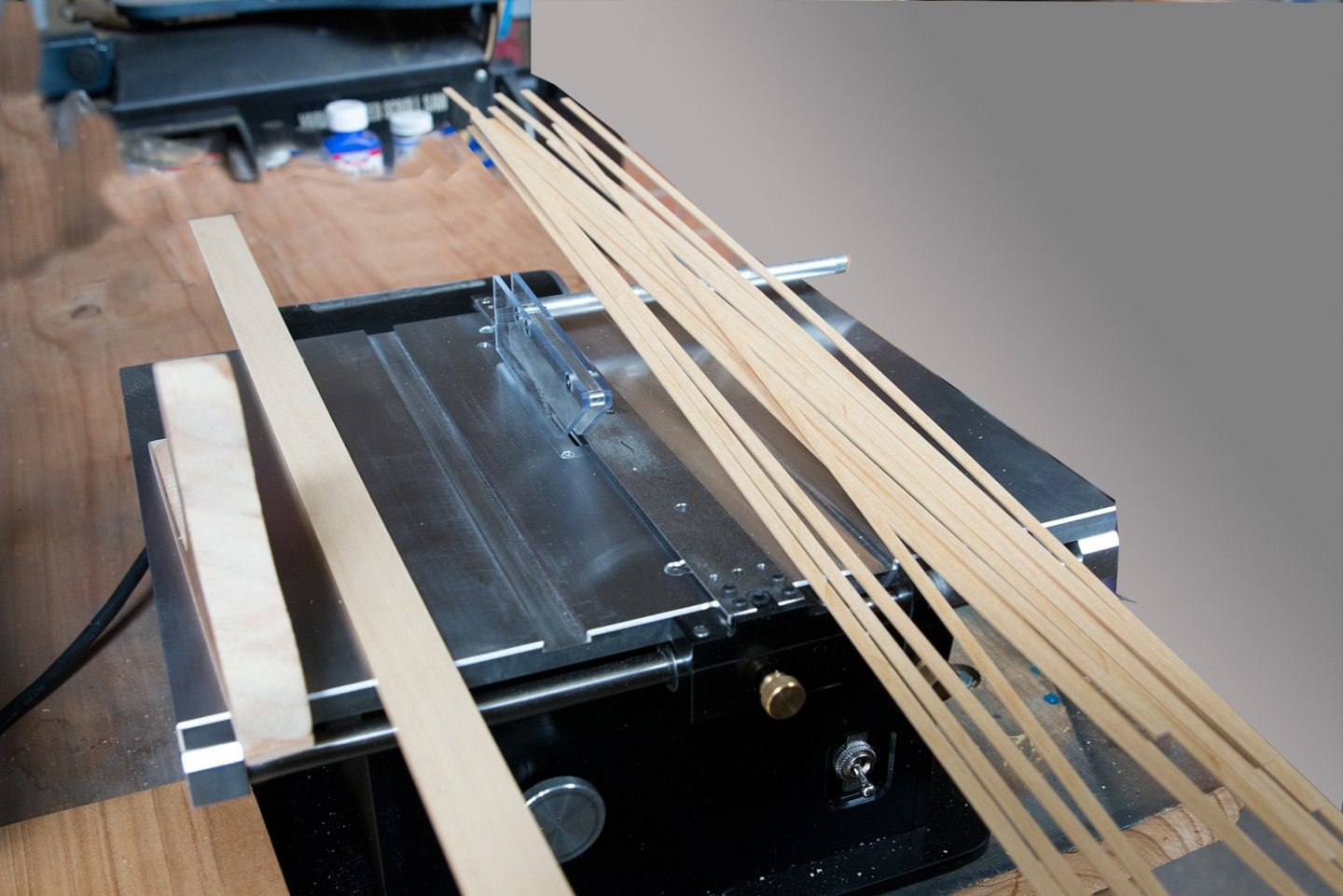
-
Ripping Planks - what I've learned from others
bartley replied to glbarlow's topic in Modeling tools and Workshop Equipment
With the longer stock all I find I need to do is to provide a bit more support at the end of a table. The problem is the longer plank tilts up as it goes off the end of the table. I just have a block of wood the same height as the table which supports the plank as it comes off the table. John -
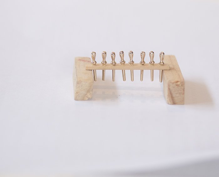
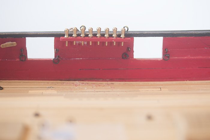
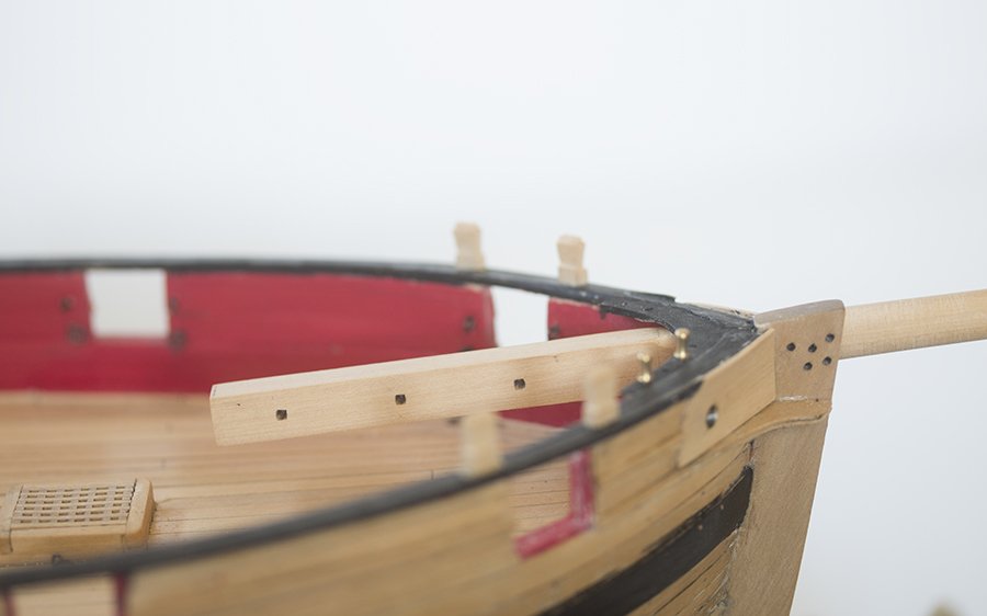
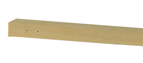
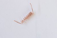
Post 33: Pin Rails I have constructed the pin rails from 3/64 strip as suggested by Chuck. He makes his own pins from 3/64 square strip but I found that my skill s could not match his especially making 20 odd all the same! so I opted for commercial brass ones. Clearly they will need some further treatment - blackening, or maybe painting to llok like wood: These fit tightly into a 1mm hole and seem to be about the correct scale. . Here I need some advice Chuck because they are only 8mm long and do not extend far below the pin rail. I have some 12 mm long ones but they need a 1.2 mm hole as you can see in this mock-up: The tops also look a bit more "authentic". What do you think Chuck? I am worried about the consequences of the short ones when it comes to rigging them. John
- 160 replies
-
- 4
-

-
- cheerful
- Syren Ship Model Company
- (and 1 more)
-
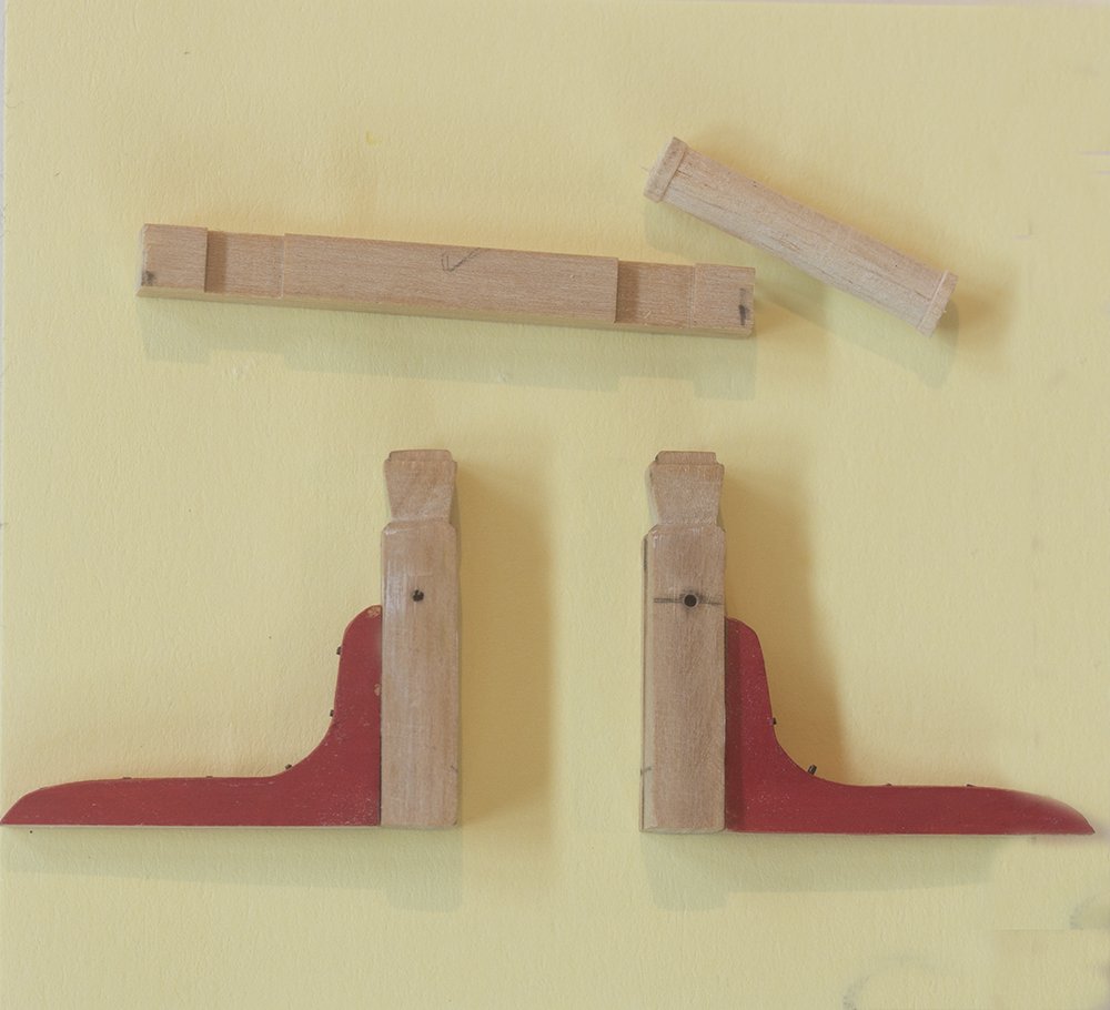
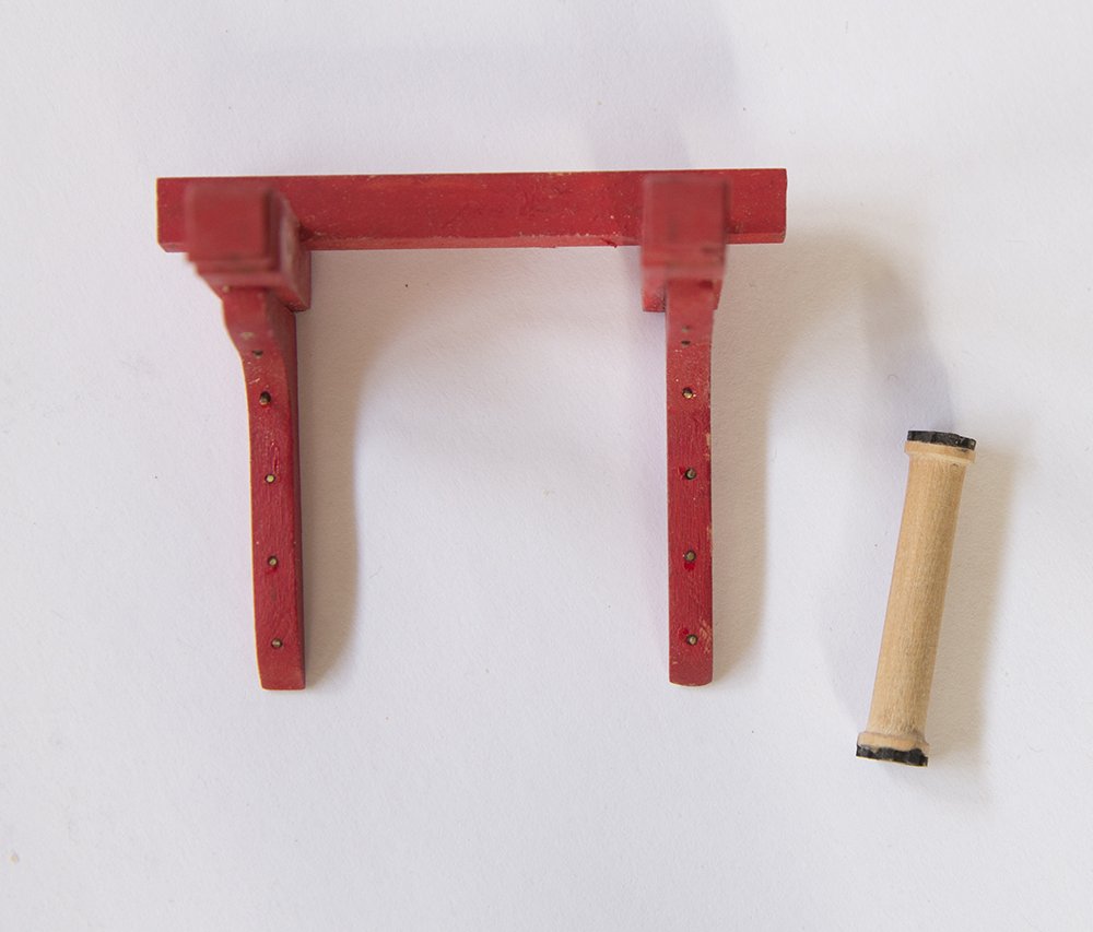
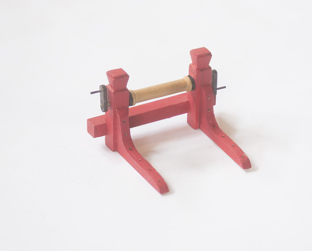
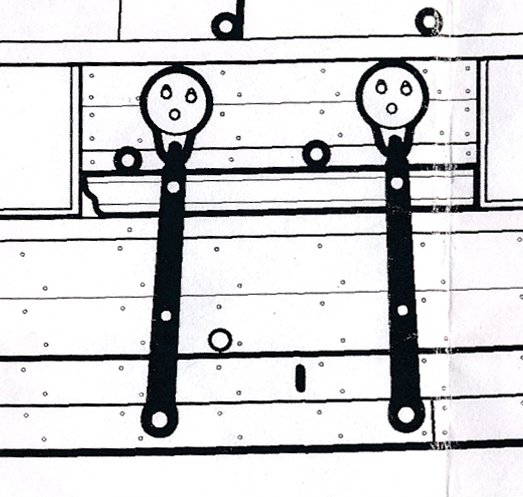
Post 32: The Winch The winch was constructed as per the plans. The posts were made from 5.6 mm square stock (7/32) and the cross beam from 4.75 mm Square (3/16). The tops of the posts were shaped in a similar manner to that fused for the timber-heads (knife and needle file): The roller was tuned on my homemade lathe to a diameter of 4 mm and the bolt heads were simulated with 24 ga blackened wire: Micro-tubing was used for the winch handles. John
- 160 replies
-
- 8
-
-
- cheerful
- Syren Ship Model Company
- (and 1 more)
-
Blackening brass
bartley replied to Bill Hill's topic in Painting, finishing and weathering products and techniques
You can buy burnished rings and eyepins, which are black but I have never seen anything "preblackened" in the sense we are talking about. John -
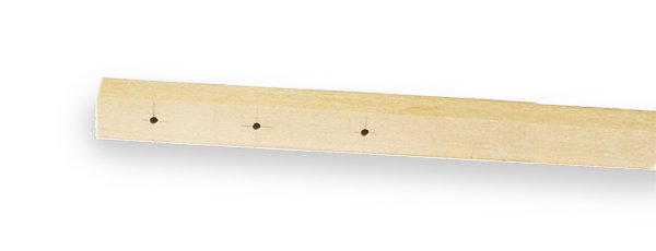
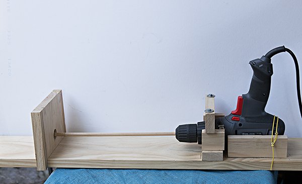
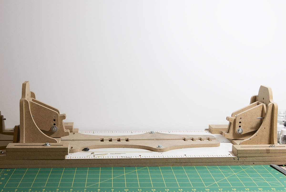
Post 31: Bowsprit I am in the process of constructing the remaining deck furniture - Windlass etc. However, I decided to make and trial fit the bowsprit so that I can avoid maneuvering around the deck fittings. I turned this from 5/16 square stock as suggested by chuck. I drilled three 1.5 mm holes while the stock was still square and also the holes for the sheave at the tip I then turned this on my home made "lathe" The board at the end has a Roller Blade bearing. I actually have two of these and on longer jobs I position one about half way along to add extra support. I find this works pretty well and is cheap! Of course I had to enlarge the hole in the bow to fit. Initially, I did this with drills of increasing diameter but this led to tearing of the timber so in the end I did most of the work with a round file. Here is the fitted bowsprit: John
- 160 replies
-
- 8
-
-
- cheerful
- Syren Ship Model Company
- (and 1 more)
-
Yes Glenn, this was done . I notice that this photo was taken nearly a year ago so I am well past that stage now. Cheers, John
- 778 replies
-
- 2
-
-
- cheerful
- Syren Ship Model Company
- (and 1 more)
-
Very impressive Glen. Have a look at mine at the same stage. Just lacks the crispness of yours doesn't it? John
- 778 replies
-
- 6
-
-
- cheerful
- Syren Ship Model Company
- (and 1 more)
-
Blackening brass
bartley replied to Bill Hill's topic in Painting, finishing and weathering products and techniques
I use a small plastic sieve to contain my parts and use Sparex to clean off the contamination. So the sieve containing the parts goes into the Sparex for a couple of minutes then into a bicarbonate bath to neutralise and wash under running water. Then into the blackening reagent (no drying). Again into the bicarbonate to quench the reaction then wash again in running water. Only then do I dry the parts before gently polishing with a micro-fibre cloth. I used to use an acetone step but no longer find it necessary. If I did I would allow to dry before the next step. But acetone dries quite quickly. John -
Blackening brass
bartley replied to Bill Hill's topic in Painting, finishing and weathering products and techniques
As has been mentioned here before, take care with this stuff .All these preparations contain selenium dioxide (or selenious acid when it is in solution- same stuff in a different form). This stuff is highly toxic so wear gloves and ensure good ventilation. Now, what is happening here is what chemists call a Redox Reaction. Modellers certainly do not need know any chemistry but there are a couple of important consequences of the chemistry. Firstly the metal (or actually the copper in the brass) is etched away by the selenious acid and goes into solution as copper ions. At the same time the selenious acid is converted to selenium metal (which is black) and this is deposited as a tiny black spec in place from which the copper was removed. So notice that the Selenium metal is not chemically attached to the metal in any way so it can be removed by mechanical action. Also although others have warned about the flaking that is a consequence of prolonged action a second effect is that more of the metal surface is etched and surface detail is compromised. Obviously this is not important for an eyepin but more significant for a cannon, say. In the minute or so that it takes to achieve a good result this would be barely noticeable but if one were persist for half an hour there would be noticeable pitting and significant loss of detail. All of these products also contain a mineral acid (nitric in Jax Black, hydrochloric in Jax Pewter Black, and phosphoric in Birchwood Casey) and they also usually contain some copper sulfate, which is there to moderate the reaction. This, of course, is the blue colour of the product The Birchwood Casey product also contains molybdate which acts in a similar way but with the zinc in the alloy. So you possibly get a deeper black since both components of the brass are being blackened. After the initial blackening most people polish the surface to remove any excess flaking. So the black stuff, which ends up on the cloth (in dvm27’s post for example) is Selenium metal which is also toxic and worse still it is a dust, which you can breath in. I would not be polishing with a power tool but if you must, wear a mask and gloves. If you get black on your fingers don’t go and eat your lunch with out washing it off with copious soap and water! John -
Hi Jaeger, On the subject of wind speed - or really "apparent" wind speed. It depends on the point of sailing. If you are sailing before the wind then as you say the apparent wind is less than the true wind speed but if you are sailing into the breeze then the apparent wind is stronger than the true wind. Also since the boat is at an angle to the wind at this point of sailing the addition of vectors causes the apparent wind to move aft. But you are definitely correct about the lack of shade on deck! John
-
Jaeger, I suspect volatility might be a factor. The IPA with a boiling point of around 83 will stay in contact with the PVA rather longer than ethanol. I don't think polarity differences are that much. IPA is marginally more aliphatic. Certainly 1-propanol has less solvent powerfor polar substances than ethanol. John
-
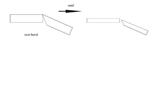
You are right Glen it doesn't take much to tighten up the joint. When I started out I tried to get it exact and as you say a little gentle sanding is all that's needed. My point was don't overdo because it will look good initially but worse after sanding. John
- 778 replies
-
- 1
-
-
- cheerful
- Syren Ship Model Company
- (and 1 more)
-
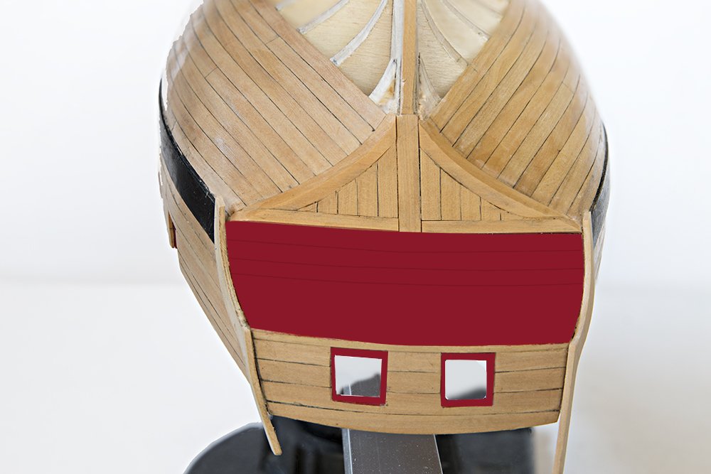
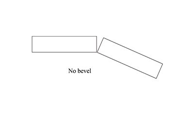
Glen, Your planking is excellent. Much better than mine which has a few deficiencies but because I was using boxwood and my supplies were limited I could not afford to rip off too many planks! On the subject of beveling - I am sure you know this as your planking is so good but perhaps for the benefit of others over beveling can be as bad as no beveling if you have to sand the hull much. So I think it needs to be reasonably correct.
- 778 replies
-
- 4
-
-
- cheerful
- Syren Ship Model Company
- (and 1 more)
-
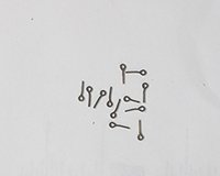
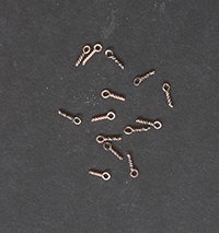
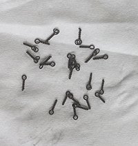
Post 30: Eyebolts and Cleats there are a number of eyebolts and several cleats to be installed and this has occupied me for the last few days. I am always concerned about these commercial eyebolts pulling out when the tension is axial. When the tension is at right angles there is not a b problem of course and here most of the deck ringbolts are not used. It has only really happened to me a couple of times but can a real pain if it happens late in the rigging process when the deck is not so accessible so I make my own by the "twisted pair" method. This is copper which is a bit soft but I cannot access brass in very many diameters. After they are made they are chemically blackened of course These were made from 24 gauge wire twisted around a 1.4 mm drill. For bolts with a ring. For bolts with a ring a 1.0 mm drill was used with the ring in the eye of the bolt. Rings were made by winding 24 gauge wire around a 2mm drill to form a spiral and then snipping it down the center. For the gun tackle eyebolts again a 1 mm drill was used. Here is a picture showing the the deck eyebolts There are several cleats along the bulwarks and for these Syren cleats were used with a bit of shaping to give a reasonable appearance. (see the image in the previous post). John
- 160 replies
-
- 10
-
-
- cheerful
- Syren Ship Model Company
- (and 1 more)
-
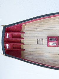
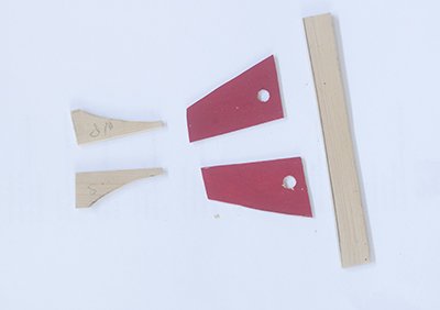
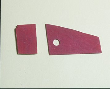
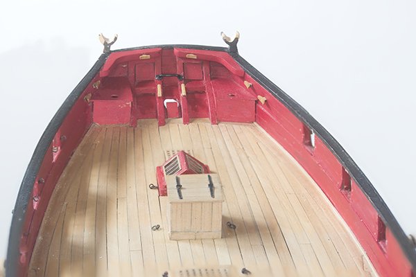
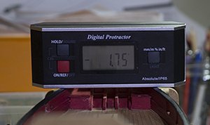
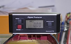
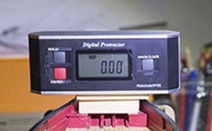
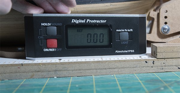
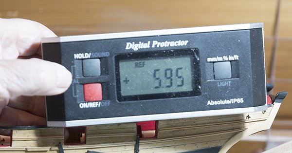
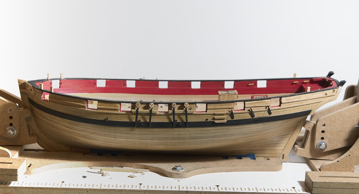
Post 29: Seats of Ease, Knees etc There are three parts to the seats of ease, top, side and front. There are some tricky angles involved.. I had taken an overhead photograph of my hull and I used this to obtain the profile of the top: .One has to be careful about using such photos. Most zoom lenses and phones suffer from barrel distortion. So if you photograph the end of your room for example the walls will bow outward. Clearly, this makes taking a profile from such photographs inaccurate. I used a prime lens which suffers less from distortion and then Photoshop knows which lens you used and can correct for any distortion remaining. Anyway I did make a card template first but the profile was so close that I went straight to the 1/32 timber. For the sides I used the profile from the transom frame Y and this was accurate enough as well. For the ends I first made a long piece extending from port to starboard matching the deck profile and making sure it was the same height on each side. Then I cut the required section next to the bulwark on each side. After assembly I checked that the heights were equal using my digital protractor. One of the advantages of these is that the hull does not need to be exactly level. I know my gunwales are level so I first placed the level between the gunwales and zeroed the device then bridging across the seats I could check the angle In fact the angle flicked between zero and 0.05. So even in the higher angle the difference in height works out to be only 0.06 mm The curve of the transom knees was obtained from the plan and the approximate angle from my overhead photo but the biggest challenge was shaping them to fit the angle of the internal transom frames. This was trial and error and I found that a had to do a bit of reshaping of the transom frames themselves. obviously this should have been done earlier but I did not predict the problem until I tried to fit the knees. so here is the inboard of the stern showing those features. The horse for the boom sheet was fashioned from 1.2 mm wire and washers were made from light card as suggested by Chuck. The cleats are from siren and have been left natural at this stage. I know Chuck point out that contemporary models show them painted red. However, any any boat I owned which had wooden cleats we found it impossible to keep any protective coating, paint or varnish on thembecause of the friction from the rope. Modern synthetic rope is not so bad but hemp is like sandpaper. I can always decide to paint them later. John
- 160 replies
-
- 6
-
-
- cheerful
- Syren Ship Model Company
- (and 1 more)
-
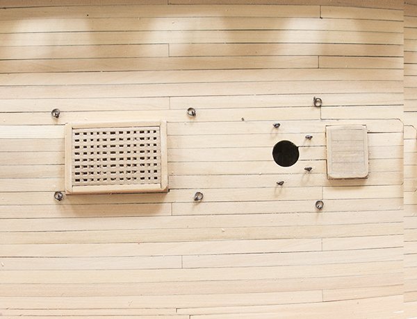
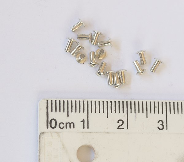
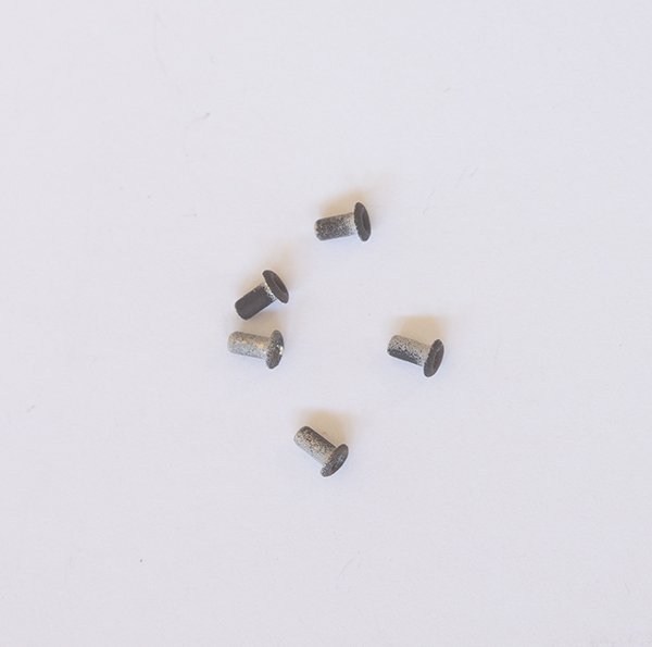
Post 28: Timberheads Once again Chuck describes how to make these. I made them in pairs (oort and starboard) so that they matched as closely as possible. I measured the angle with my digital protractor: This got me started but in the end I eyeballed it. It is surprising how a very small difference in angle is noticeable. You will also notice that I have installed the scuppers. Here rather than just use a hole as indicated on the plans I used rivets to fill the holes . These are used on electronic circuit boards and have an internal diameter of 1 mm and fit into a 1.6 mm hole. I blackened them first of course.
- 160 replies
-
- 10
-
-
- cheerful
- Syren Ship Model Company
- (and 1 more)
-
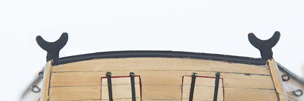
Post 27: Boom Crutches I found these tricky. The procedure for constructing them is well described in Chuck's post so as I tried to follow this I don't see a point in repeating his excellent description. Nevertheless, several attempts ended up in the bin before I obtained something reasonable and even now they are far from perfectly matched. Fortunately the black paint hides a multitude of sins! John
- 160 replies
-
- 5
-
-
- cheerful
- Syren Ship Model Company
- (and 1 more)
-
Proxxon DB250 mini wood lathe
bartley replied to Jorge Hedges's topic in Modeling tools and Workshop Equipment
The 250 mm center distance can be limiting. For example the bowspit on my Cheerful is 310. So I have the extension table which allows me to turn longer pieces such as masts. John- 11 replies
-
- 2
-
-
- db250
- mini lathe
- (and 1 more)
-
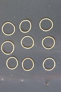
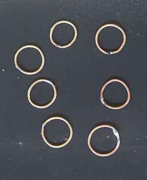
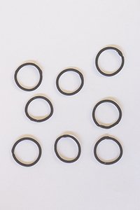
Post 26: Chain Plates deadeyes etc I made the backstay plates and the chainplates as described by Chuck. I am not sure what the correct procedure is for making the deadeye strops is but here's what I did: I made some rings by wrapping 22 gauge wire around a 6.3 mm diameter dowel Then silver soldered them closed Blackened them Then crimped them around the deadeye The plans show the chainplates nailed to the wales then to the hull then to the channel. I thought this involved an ugly kink so I put two nails in the wales and one in the channel. John
- 160 replies
-
- 8
-
-
- cheerful
- Syren Ship Model Company
- (and 1 more)
-
My wife and I are keen opera fans and although there is no live opera at the moment, the Metropolitan Opera in New York is streaming a different opera every day including some performances from the 60's and 70's starring performers like Big Lucy Pavarotti and the legendary black American soprano Leontyne Price. The effect on my ship modelling can be seen in the attached photo! John
- 160 replies
-
- 6
-
-
- cheerful
- Syren Ship Model Company
- (and 1 more)
-
Glenn, After my parcel from CMB sat in Heathrow for two weeks it is suddenly in Sydney. So that's three weeks compared to the usual two. So unfortunately you are probably right - you parcel has gone astray, Bad luck. No wonder Chuck is not keen to post abroad at the moment. John
- 778 replies
-
- 2
-
-
- cheerful
- Syren Ship Model Company
- (and 1 more)
-
Thanks Chuck, that's pretty clear now. Actually the last photo in Chapter Nine shows it quite clearly. I didn't look far enough forward! John
- 160 replies
-
- 3
-
-
- cheerful
- Syren Ship Model Company
- (and 1 more)
-
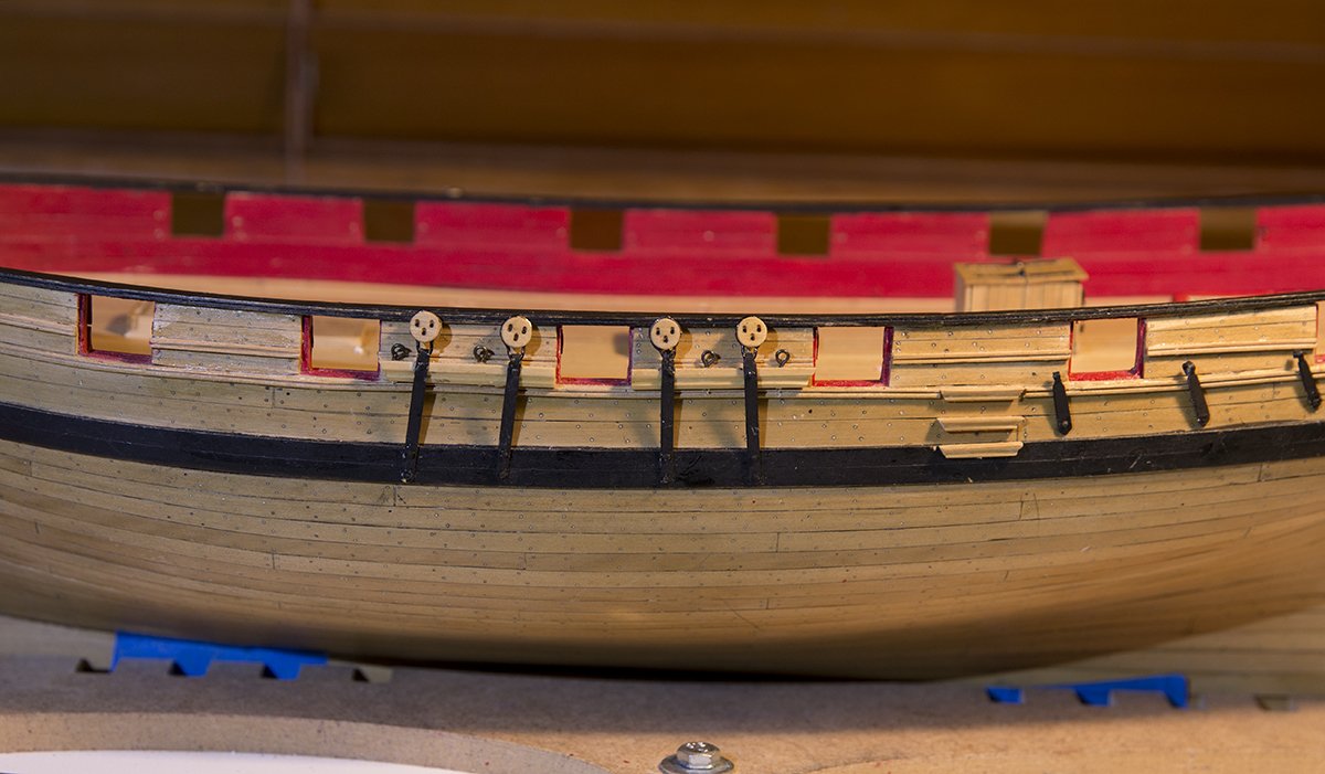
Chuck, Here's a pic. I see two eye bolts between the deadeyes and two on the cap rail there is a scupper port also but there is also something marked on the wale between the straps.
- 160 replies
-
- 2
-
-
- cheerful
- Syren Ship Model Company
- (and 1 more)
