bartley
-
Posts
424 -
Joined
-
Last visited
Content Type
Profiles
Forums
Gallery
Events
Everything posted by bartley
-
There are really only two versions of Artistic Wire to consider: "black" and "bare copper". The black is quite glossy and in my opinion does not look like rope. Bare copper can be blackened with one of the selenium products like Jax Black. The plated versions are coated and could not be blackened this way. Alternatively, you could use Chuck Passaro's method where he paints the item black and then uses weathering powder to make it look more like metal. Incidentally, this wire is not stranded. It is essentially copper wire with an enamel coating (except for "bare copper" of course which has no coating. John
-
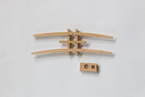
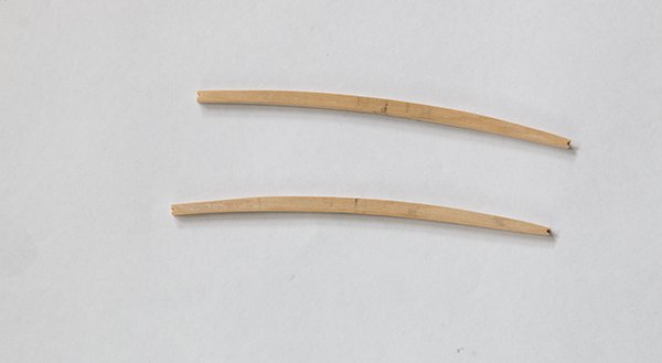
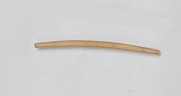
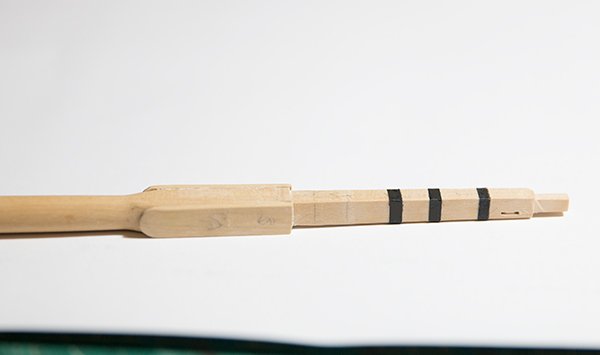
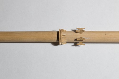
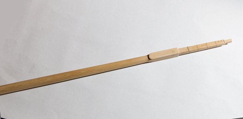
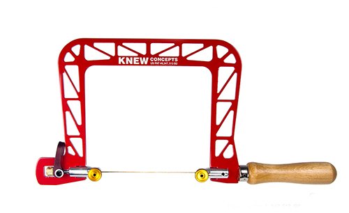
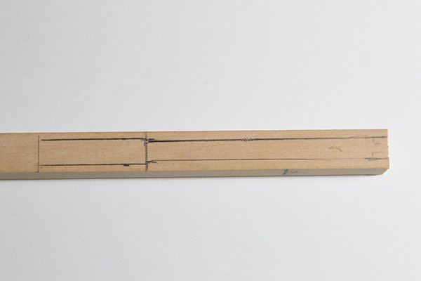
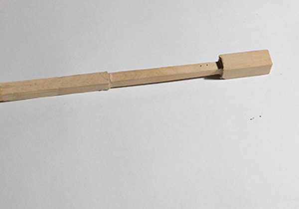
Post 50: Constructing the Mainmast All the deck features are now complete and it is time to start on making the main mast. The mast itself was made from 13/32 square boxwood. I decided that it would be easier to establish the square section at the head of the mast before rounding it. Once this was done I first planed the edges to form a hexagon using the 710 7 rule and then turned the lower section on my home made lathe powered by a hand drill as described earlier. The next task was the curved cross pieces for the cross trees. I cut these using my Knew Concepts jewelers saw. These saws are a joy to use. The lever system ensures that the blade has the same tension every time and I find I can cut really close to the line . They were then sanded to shape using sanding sticks and files The slots in the linking pieces were cut on the mill and the unit put together. The mast cap was simply made from 5/32 sheet with two round holes drilled at the appropriate distances and one of the squared with file to take the square tennon at the top of the mast. The boom support ring and the mast hoops were fabricated on the mill using the rotating head as described earlier for the mast coat. Cleats from Syren were sanded to shape and added below the boom ring The cheeks were fabricated from 3/54 sheet and the metal bands simulated with black pin-striping tape John
- 160 replies
-
- 9
-

-
- cheerful
- Syren Ship Model Company
- (and 1 more)
-
Actually, too long Tom. Being a chemist I know a bit about the technical side of this. The selenium in the blackening agent etches tiny pits in the brass and black selenium is deposited there. If you continue another layer deposits on top of this and this rubs off easily. There is a kind of happy medium between incomplete blackening and too much flakey stuff. The exact time depends on how much you dilute the reagent. Incidentally, watch out for this flakey stuff. It is selenium and is toxic. Wear gloves and wash you hands well afterwards if any gets on your fingers. John
-
Yes, there is no adjustment on these. Our x and y are perfect - easily adjusted but not sloppy. However, the z one is tight as you describe. Maybe a bit of dust which might blow out with compressed air or very small touch of lubricant. Good work by the way - certainly surpasses mine. John
- 778 replies
-
- 2
-
-
- cheerful
- Syren Ship Model Company
- (and 1 more)
-
Glenn, I think I mentioned this once before but all machine knobs like this have backlash. This is like a kind of deadspot where rotating the knob dos not change the setting. It is very small but on fine readings it can make a difference and means that if you set a reading by rotating the knob clockwise you will get a different setting than if you rotate it anticlockwise. so you should always approach a setting from the same direction. John
- 778 replies
-
- 3
-
-
- cheerful
- Syren Ship Model Company
- (and 1 more)
-
This is true, but if you use a cow hitch at the first and last it kind of simulates this. John
-
Glenn, This is not quite true here. On a square rigger the wind does indeed come mostly from the aft quarter and so the seats of ease were locate in the bow. Hence the term "heads". However, this cutter is fitted with large fore and aft sails so she would sail mostly into the wind and hence the seats of ease are located aft. Your other comments are true though. In modern times we would be a bit squeamish about such an open arrangement. John
- 778 replies
-
- 3
-
-
- cheerful
- Syren Ship Model Company
- (and 1 more)
-
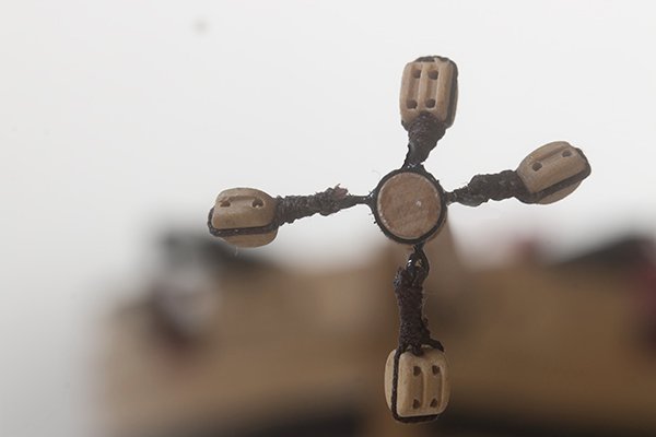
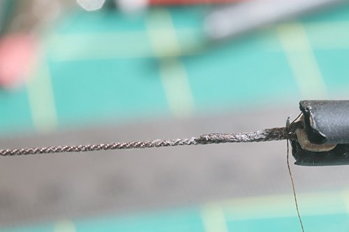
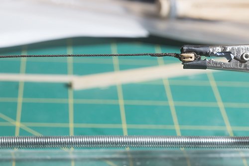
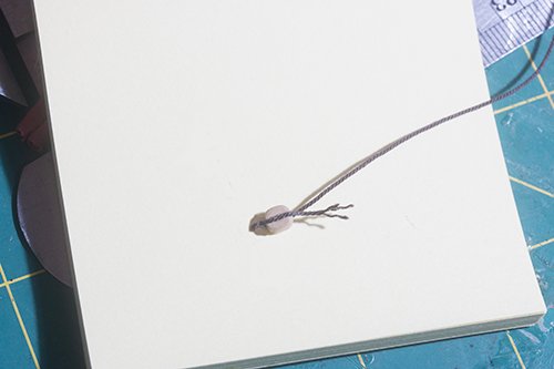
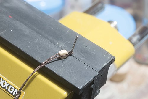
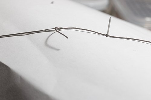
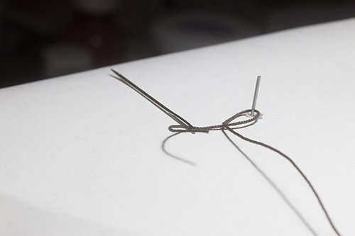
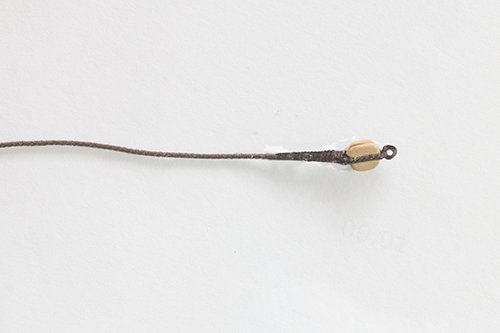
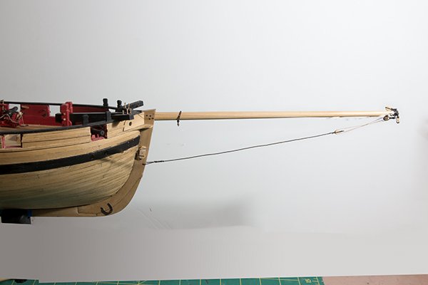
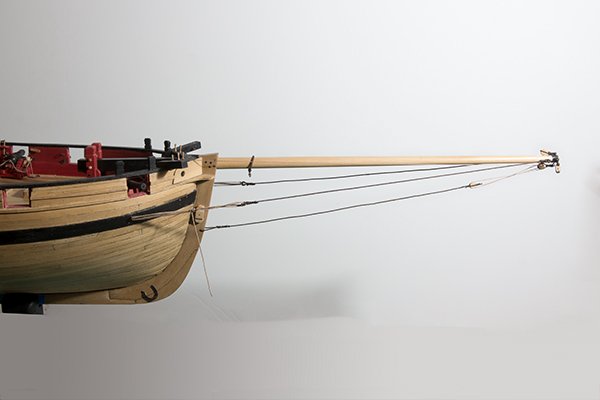
Post 49: Rigging the Bowsprit 4 blocks need to be installed on the the ring-bolts at the end of the bowsprit: The bobstay needs a block with a becket seized on one end. My method is established from several posts on this site but I include it here for completeness I start by forming the becket. I do this by wrapping the line around an appropriate sized drill, passing a needle through the line an pulling it tight I seal this with a drop of CA and stiffen the becket with shellac. Now I add the block and glue it to the line with PVA. Then I begin the false splice by fraying the ends cutting them on the diagonal, adding a drop of PVA and rolling the splice between my fingers Since this bobdstay is seved for its whole length I serve over the splice as well In order to thicken the splice a little I wound some 0.3 mm line just over the splice itself. The other end of the bobstay is spliced to the stem in a similar way and then the block is reeved to the lower 3/16double block on the end of the bowsprit. The bowsprit guys were made in a similar way but spliced onto thimbles. a hook fabricated from 24 gauge wire was added to the outer The whole assembly was attached as shown in the plans between the ring-bolt at the and of the bowsprit and the ring bolt in the bow of the hull None of these was tightened at this stage. I will wait until the rest of the bowsprit rigging is in place. John
- 160 replies
-
- 7
-
-
- cheerful
- Syren Ship Model Company
- (and 1 more)
-
Actually, there is more sec -butanol in their thinner than iso-propanol so I would stick with their thinner rather than try to use a substitute
-
Did you use Tamiya thinners or some other brand? There looks to be an incompatibility somewhere here. As Ron points out you should use their thinner even though it is quite expensive John
-
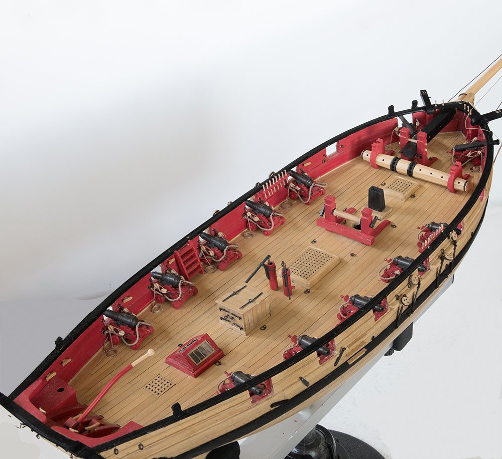
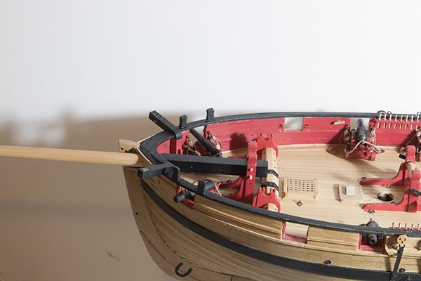
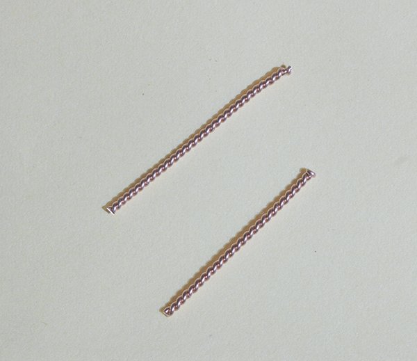
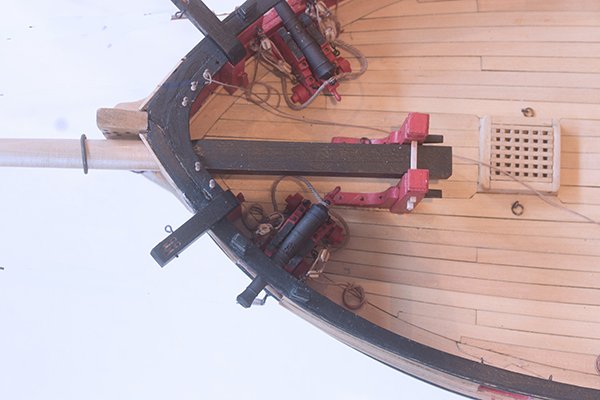
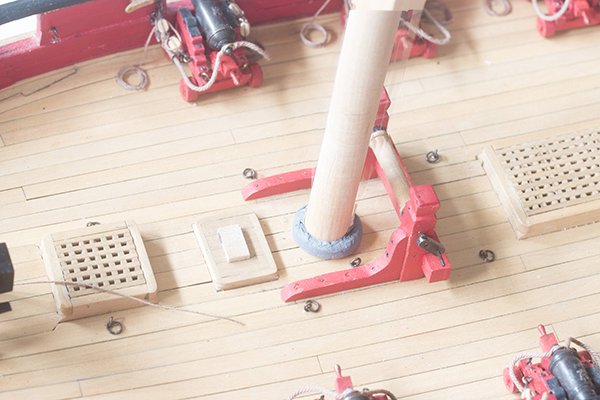
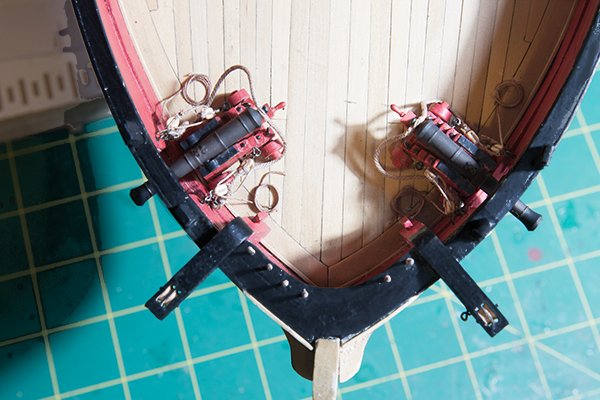
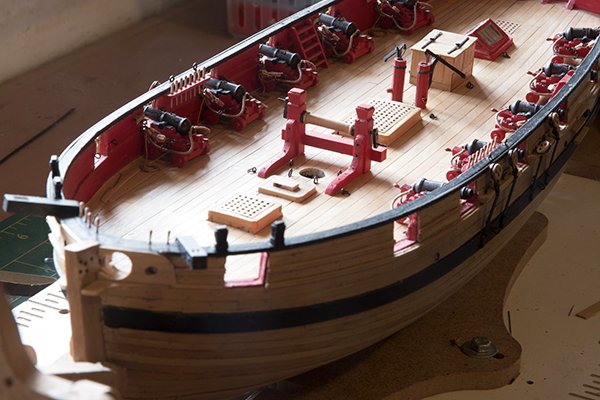
Post 49: Bowsprit Installation The bowsprit itself was constructed and test fitted earlier when there was less deck furniture to obstruct it. It is now time to install it permanently. The bowsprit is fed through the bulwark hole hole in the bow and inboard end is located by the lower strip of the bowsprit step. As Chuck points out it is not necessary for the strip to bass all the way through the bowsprit. The strip can be cut in half and inserted about half way through the bowsprit from each side . It appears to go all the way through. The windlass fits behind the bowsprit step with the pawls engaging in the ratchet wheels. In fact, when I was manipulating the bowsprit later on the bowsprit step detached. It was clearly not glued down securely. I had to remove the windlass to attend to this and the bowsprit step is now re-glued pinned to the deck with twisted pair pins like these: Whilst on the subject of the fore-deck it is clear that once the bowsprit and step are in place there is insufficient room for recoil of the port chase gun. This fact has been pointed out by several other builders. The second gun-port is vacant but positioning this gun there makes it look unsymmetrical. The plans show the gun in this position and and the specification calls for "two 6 pound chase guns" so I have chosen to leave it positioned as shown even though it could probably never be fired in this position. John
- 160 replies
-
- 5
-
-
- cheerful
- Syren Ship Model Company
- (and 1 more)
-
Wow! Thanks guys. The knowledge on this site is amazing. I will let my friend know. John
-
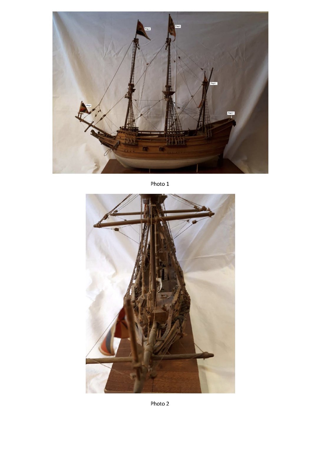
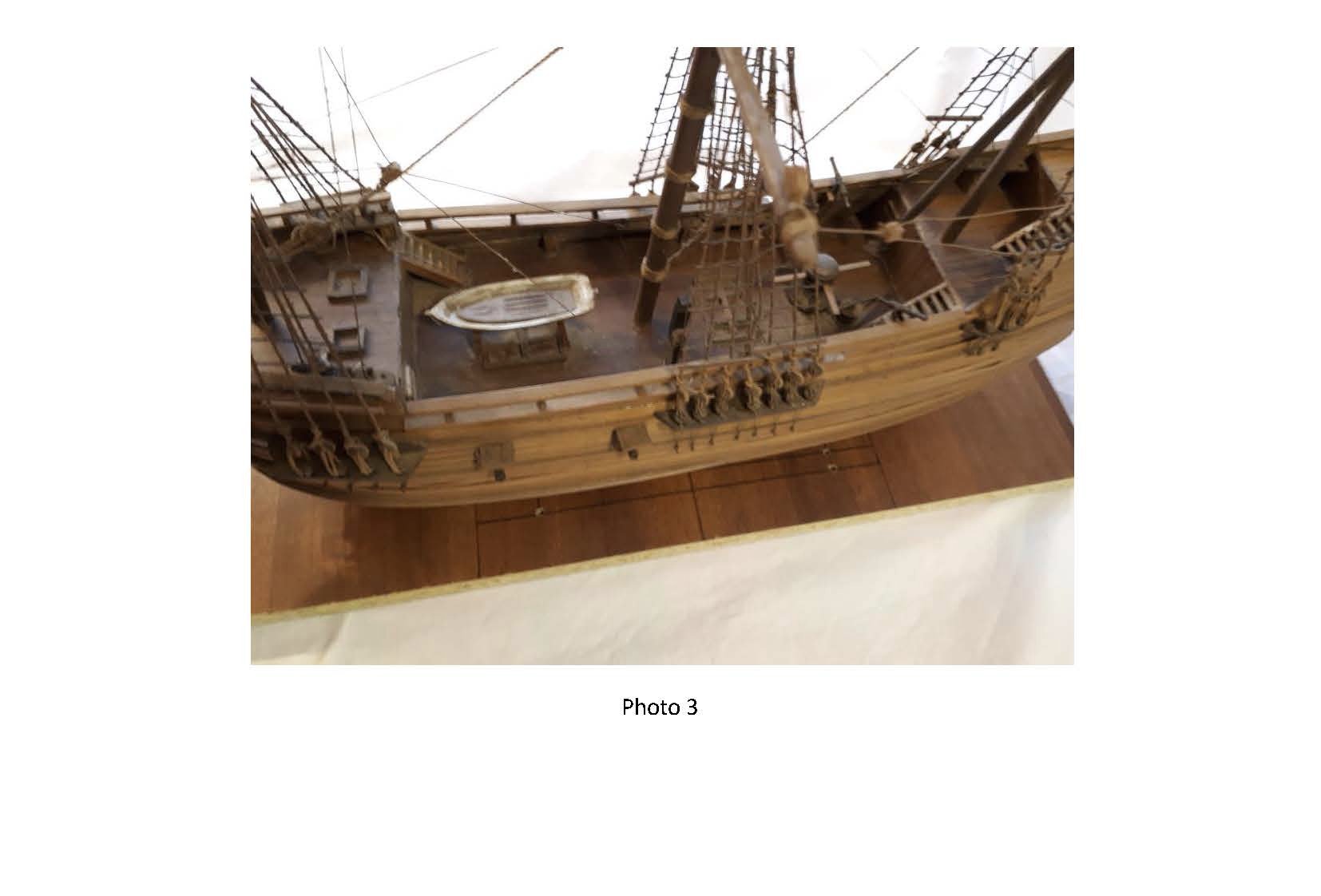
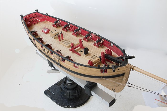
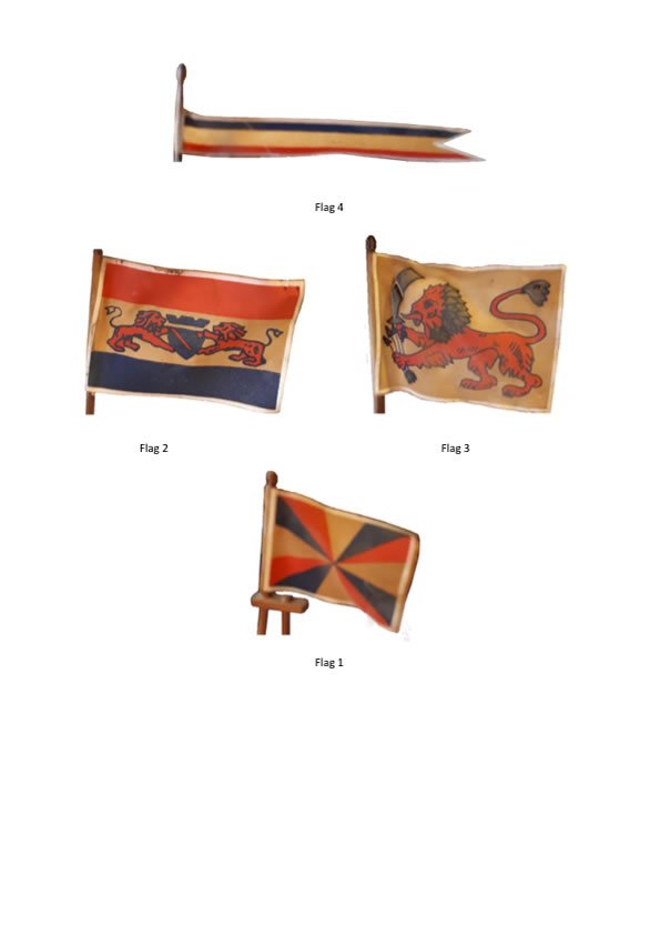
A friend of mine who lives in Italy has been given this ship but he knows nothing of its history. can anybody shed some light on th type of ship? the flags may be of some help. John


-
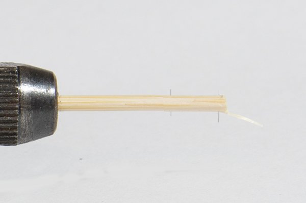
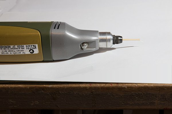
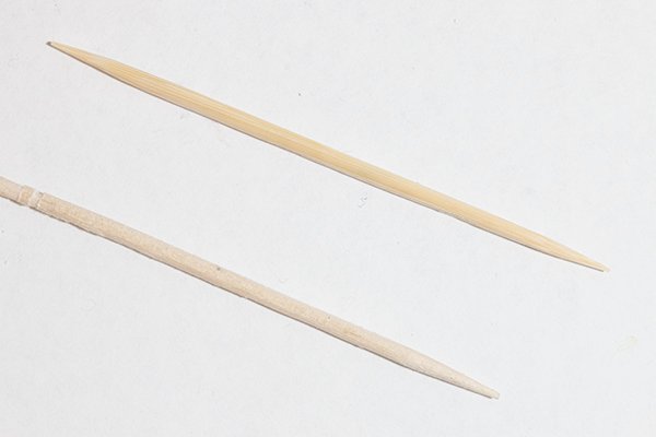
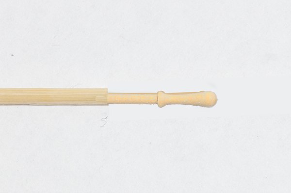
Yes Glenn, I agonized over these belaying pins. In the end I started with some tooth-picks like these Chucked them into my hand held Proxxon I then marked the vital transition points on a paper behind and used files and sanding sticks too turn the shape Initially I could not make two the same! However, like most such endeavours, I improved with practice. Even so I probably made 40 to produce the 20 or so required. I think you have a lathe so it might be a little easier. John
- 160 replies
-
- 3
-
-
- cheerful
- Syren Ship Model Company
- (and 1 more)
-
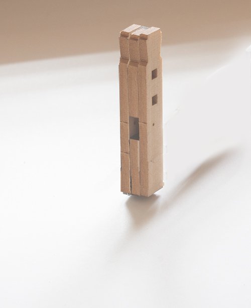
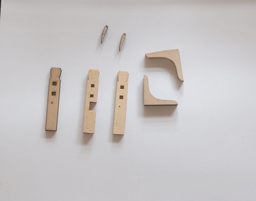
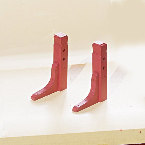
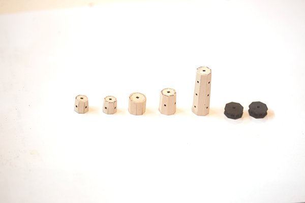
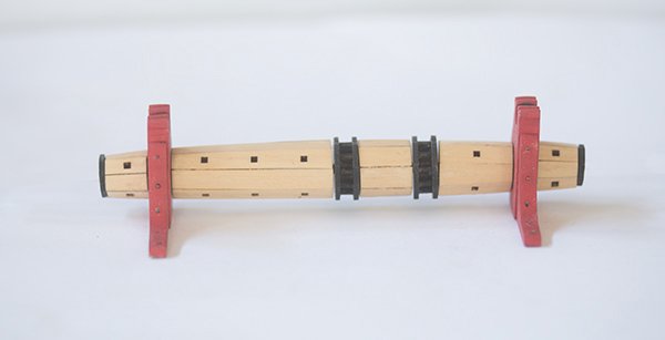
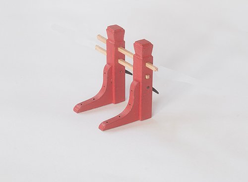
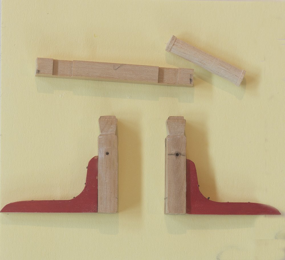
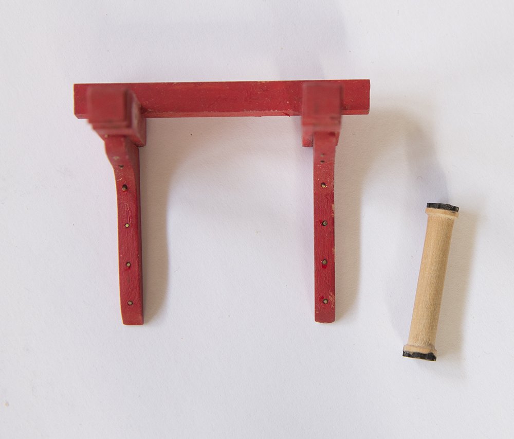
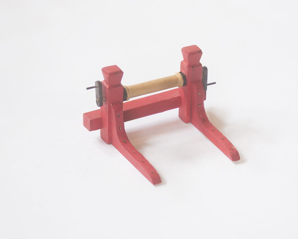
Post 48: Bowsprit step and Windlass To complete the fore-deck paraphernalia there are two more nice little mini-kits from Chuck. First up was the the bowsprit step: This could be scratch built but the square holes might present problems. So the kit looks like this: The uprights are constructed in three parts It is important to sand these well so that the joins are not visible after painting. The brackets are then added I simulated the bolts with 24 gauge black wire. After filing these flat the brass ends were chemically blackened with a selenium based product. I find that there is no staining of painted timber using this technique but bare timber often does show some staining and more care is needed. The pawls were painted black and weathered with rusty brown powder as suggested by Chuck for all metal parts. These were pinned through. the uprights and finally the uprights were joined with 1/16 inch square boxwood strips, left unglued for the moment. Next up the windlass which would be a real challenge but thanks to another kit from Chuck I nice, though challenging job, can be made First a set of " barrels" is constructed on hexagonal end pieces These are threaded onto a square boxwood strip and the supports and end-pieces added before guleing the whole lot together. The bowsprit itself was made some time ago and the hole in the bow widened to allow a tight fit of the bowsprit so the next task is to install the bowsprit permanently. John
- 160 replies
-
- 5
-
-
- cheerful
- Syren Ship Model Company
- (and 1 more)
-
Mast Coat Revisited As Chuck points out in his monograph, the version of the mast coat he presents is somewhat stylized. In reality a circular set of wedges were driven in around the mast and these were covered wit canvas. In view of this I produced a more "authentic" version. The two versions are shown below: In fact in, keeping with the style of this model, I think that Chuck's stylized version looks better. What do you think. Guys? John
- 160 replies
-
- 5
-
-
- cheerful
- Syren Ship Model Company
- (and 1 more)
-
Glenn, This mast coat is superb, as is the rest of your work! I made mine the same way (and I thought I discovered the method!) I was going to have another go to try for a better profile than the one I showed in my log but I am having second thoughts. I know this is what Chuck shows in his log but, with all respect to him, I think he has used a bit of poetic license. I understand that in practice a set of wedges was used around the mast and these were covered with tarred canvas. Maybe I will try to model this. John
- 778 replies
-
- 1
-
-
- cheerful
- Syren Ship Model Company
- (and 1 more)
-
This may not be the proper place to talk about machine accuracy but since it has cropped up here I thought that I would add some comments. First and foremost this machine is in my opinion certainly accurate enough for our purposes. Derek says that the accuracy is 0.01 (based on the scale markings) but this is only an estimate and is in fact the maximum possible. The only way to determine the accuracy is to do an experiment. Also, as with any scientific measurement, we need to distinguish between "accuracy" and "precision". For example lets imagine I throw ten darts at a board aiming at the bulls eye. All darts miss the bull by 100mm but all are grouped in an area of only 10 mm. So the precision (repeatability} is good but the accuracy is poor. So accuracy is how close a measurement is to the expected value and precision is repeatability of that measurement. So, my friend and I have measured these parameters on his Proxxon mill. We used a new sharp bit and cut two grooves nominally 10 mm apart (10 rotations) into a boxwood sheet. The measured distance between them was around 10.08 so the accuracy is + 0.08 in 10. Sounds bad but this is only 0.8% - actually pretty good. However, when we did this 10 times the measurements varied from 10.06 to 10.10. Thus the precision is +- 0.02 - very good and way beyond what the eye can see on a model. The other thing to remember is that there will be backlash so that for best results you should always approach a setting from the same side. I always set by turning the dial clockwise so if you need to get to a mark with an anticlockwise turn go past the mark and come back clockwise. Hope this helps. John
- 778 replies
-
- 7
-
-
- cheerful
- Syren Ship Model Company
- (and 1 more)
-
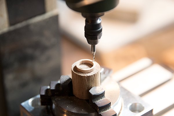
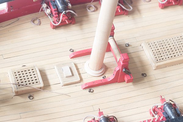
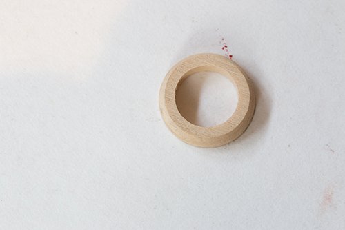
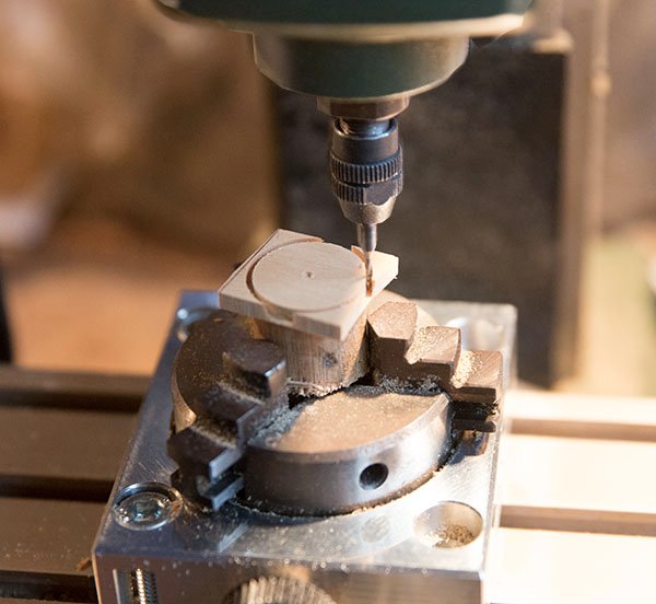
Post 47: Mast Coat This item was made on my friend's Proxxon mill. I have mentioned before I do not own one of these but since I have taught him a thing or to about its operation and because I cut planks for him he is happy with the arrangement. In my working life I have been involved with the contract hire of equipment and although there is no fee involved here it suffers from the some of similar problem in that one does not learn by exploration as one would with full ownership, Anyway the technique was to glue a 1/8 inch square plate to a dowel and use a rotating head to cut the ring: There are a couple of important point in setting up this head otherwise the item will be oval not round. 1. It must be a right angles to the table. Use a set square to check this. 2, The mill head must be centered on the rotating head. There are several ways to do this but I use a dial indicator mainly because I have one. Using the shaft of the mill bit set the dial to just touch then rotate the bit 180 degrees and check the other side. If there is a difference move the table until both sides are give the same reading . Here is an example: I am not completely happy with this profile but we are going to purchase some bits with different geometries and then I mighr have another go. John
- 160 replies
-
- 5
-
-
- cheerful
- Syren Ship Model Company
- (and 1 more)
-
Post 46: Chase guns The two 6 pound chase guns on the fore-deck were constructed the in same way as the carronades except that I made the breech rope a little longer since the barrels are longer. Using the rule of thumb of 3X the barrel length gives about 110 mm. This seemed a little long and 90 mm would seem to clear the bulwark on recoil so this was the length that I used. John
- 160 replies
-
- 7
-
-
- cheerful
- Syren Ship Model Company
- (and 1 more)
-
Hull Planking Question
bartley replied to tomsimon's topic in Building, Framing, Planking and plating a ships hull and deck
Jaager, some of your facts here are a little misleading. 1. Not all PVA preparations are acidic. There are many different formulations. Titebond has a pH around 2.6 but craft PVA and Bookbinder's PVA are neutral (pH7). The flip side of this is that the tack time is much longer with neutral preparations so they need clamping. The tack time for Titebond is only about 2 min. 2. When vinyl acetate polymerizes to poly vinyl acetate no acetic acid is released ( it is the vinyl group which reacts) but if the product is acidic then that catalyses hydrolysis of the acetate side chain to form acetic acid and this process can continue for years. Bookbinder's PVA is considered archival because the neutral pH slows the hydrolyses markedly although probably does not prevent it altogether. 3. Polymerization, as you say, does continue slowly for some time but it is not that processes that releases the acetic acid. John -
Post 45 Installation of the winch. The actual winch was constructed some time ago (in Post 32) as a little scratch build: Here it is mounted on the deck John
- 160 replies
-
- 8
-
-
- cheerful
- Syren Ship Model Company
- (and 1 more)
-
garthog, I don't know the answer to this but the curve is very gentle, as you find out when you do it on a model. Depending on the timber I suppose they may have edge bent them with the help of steam. They did also force trees to grow with bends in them but considering their woodworking skills they may have just cut them from a wider plank. John
- 778 replies
-
- 2
-
-
- cheerful
- Syren Ship Model Company
- (and 1 more)
-
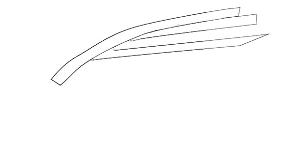
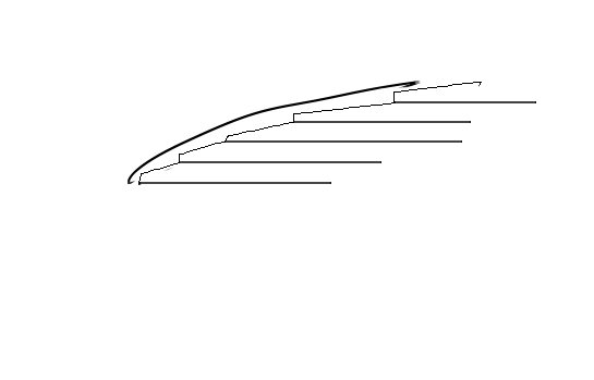
Warthog, The main issue on deck planking was to avoid "pointed" planks because these would certainly leak. so methods were developed to produce a more right angled cut. Prior to about 1850 the method was to curve the planks so that only a few on the outer edge needed any kind of special treatment. The method was to used hooked scaph joints against the waterway as Glenn describes. When I look at these I feel there is still a degree of "pointiness". A later method was to use nibbing, where planks were parallel and cut into the waterway. This method was probably superior. John
- 778 replies
-
- 9
-
-
- cheerful
- Syren Ship Model Company
- (and 1 more)
-
This is Ed Tosti's technique described in his Young America log and, as Amateur points out, it is the only way to go when the angle of the shroud changes radically. The "paperclip method will make line of the deadeyes trend donward. John