bartley
-
Posts
424 -
Joined
-
Last visited
Content Type
Profiles
Forums
Gallery
Events
Everything posted by bartley
-
Yes mini that is very true you only want a touch of weather helm. And I did not want to complicate things with other factors. It is also much more complex when there is more masts. I have mostly only sailed with Bermudu rigs where things are fairly simple. In the earlier discussion I read people had no idea why there should be any rake at all. The point of sailing is another issue. One should really change the rake as you come of the wind and I have seen people do this. But I was trining kids up to about 18 and this is wway beyond the level required. John
-
I just noticed a rather old discussion about mast rake and the reasons for it. In another life I taught kids to sail and to set up their boats for best performance. So mast rake was an important topic for discussion. There are two reasons for it. The first is due to the effect on the "helm" or the steerage of the boat. The sail obviously drives the boat forward but it also creates a turning moment which which tends to rotate the boat about its keel. The sum of all of these the force all over the sail can be thought of as acting at a single point on the sail called the "center of effort" and the position of this is affected by mast rake. It is vital to arrange things so that if you let the tiller go (by accident perhaps) the boat rotates "into the wind". The boat will then stop. This is called "weather helm" and is really a safety feature. The other direction of rotation would be dangerous as speed would increase and a small boat would probably capsize. However, there is another reason which is often overlooked. Because you have set your boat up with weather helm it will be necessary to pull the tiller slightly to windward in order to keep the boat on course. This slight inclination of the rudder creates "lift' or "drive" under the water. This adds to the drive from the sails but also reduces the amount of heal caused by the wind pressure. I know this sounds complicated but anybody who has sailed will have felt the effect of these factors. John
-
Yes indeed wefalck, Thread sizes are something of a minefield. I find the the number you get on the 'gammoning' method very much depends on how tightly you wind the thread. As you say, thread changes shape under tension, and it may not even be cylindrical. An then there is Fly tying thread, which is measured in 'Aught' producing number like 8/0 etc. I have the following conversions for Uni-thread but it will be different fo other manufactures such as Veevus; 3/0 266 Denier 6/0 130 Denier 8/0 71 Denier 14/0 32 Denier A few years ago I published the result that probably really matters What is the diameter of the resulting served thread? Here is what I found: I used three different threads: Veevus 16/0 fly tying thread diameter -. 04 mm Veevus 8/0 fly tying thread diameter -. 06 mm Guttermann Ne50 cotton thread diameter 0.114 mm I used Chuck's rope and the results were: 0.88 mm rope served withwith16.0 fly tying thread diameter 0.936 0.88 mm rope served with Ne 50 Guttermann Cotton diameter 1.11 1.12 mm rope served withwith16.0 fly tying thread diameter 1.36 1.12 mm mm rope served with Ne 50 Guttermann Cotton diameter 1.47 1.37 mm rope served with Ne 50 Guttermann Cotton diameter 1.60 (with the lay) 1.37 mm rope served with Ne 50 Guttermann Cotton diameter 1.71 (against the lay) This Guttermann Cotton is yet another sizing issue : It is described as C Ne 50 and stands for: 'English Cotton Count (Ne C) Number of 840 Yard Hanks in 1 pound of thread.' Regards, John
-
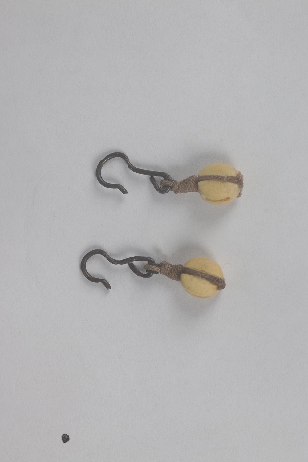
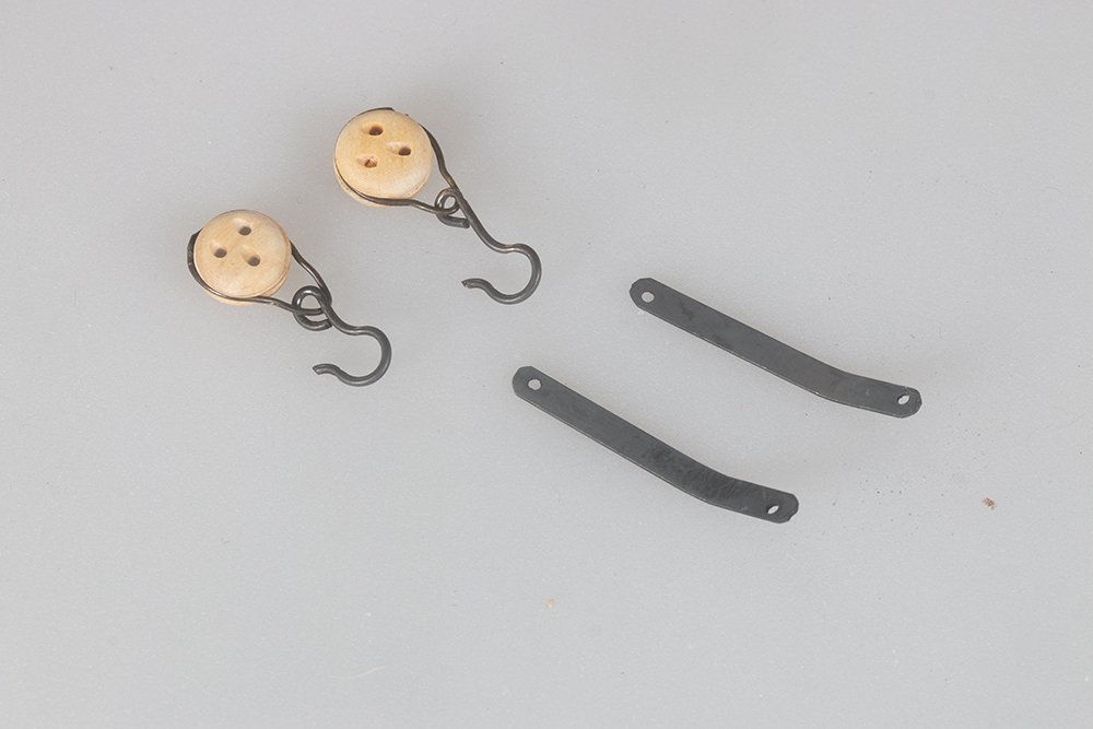
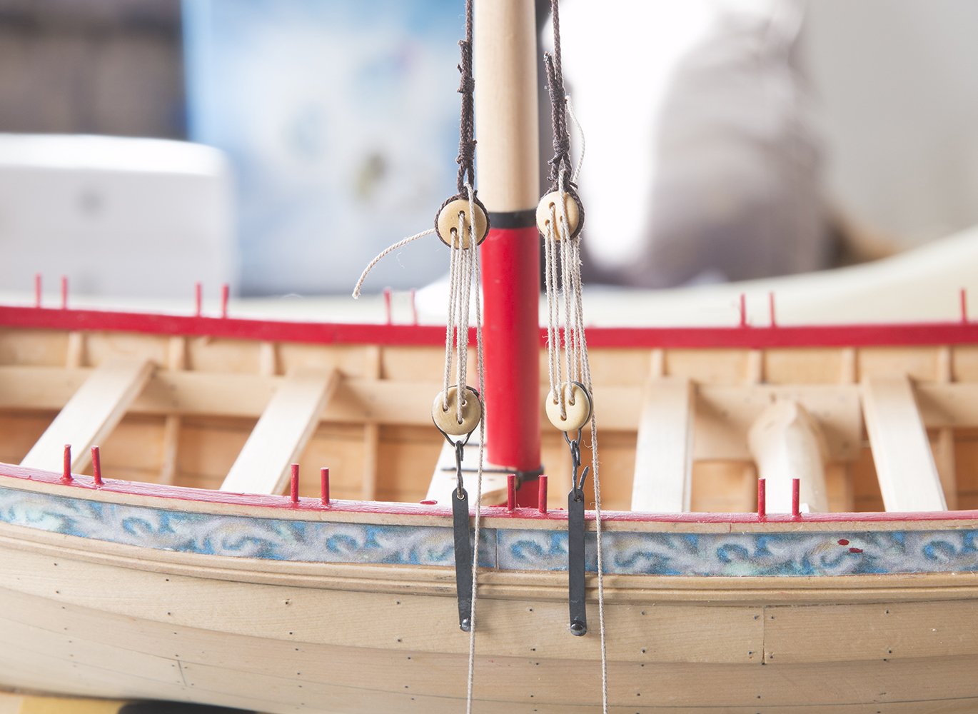
Back Stays The installation of the back stays was straight forward. The straps had already been installed earlier aft of the mast. Two 1/4" blocks were seized to hooks to hooks to fit these straps. After seizing the falls around the mast they were reeved to these blocks: John

-
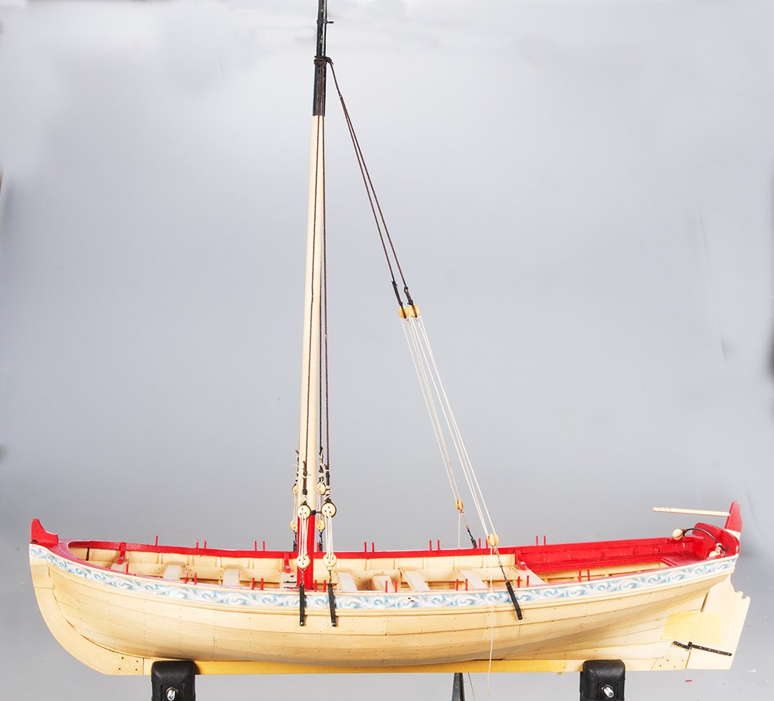
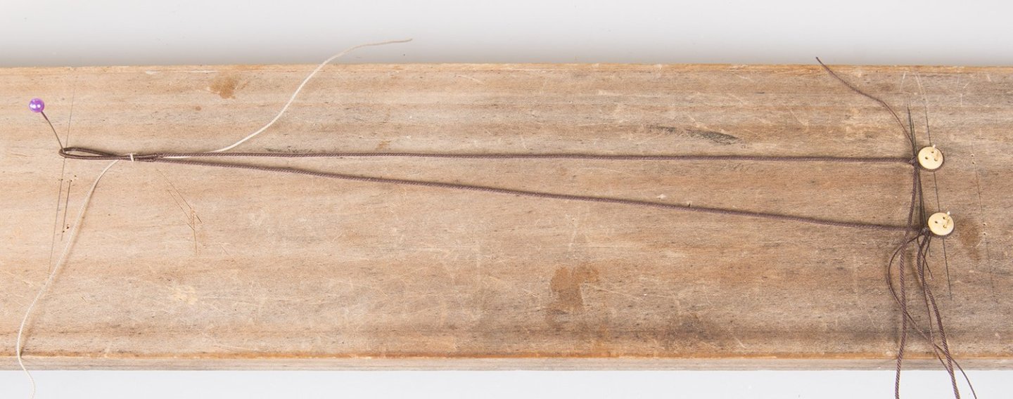
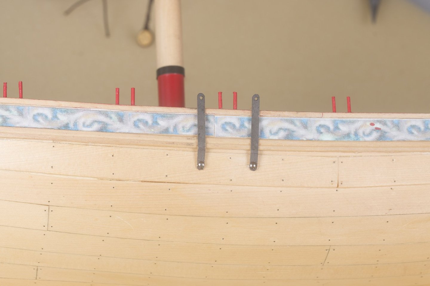
Rigging For once I elected to deviate from Chuck's monograph and install the shrouds and other standing rigging before the running rigging for the boom and gaff. I normally rig my mast from low to high so that I can fabricate the stays, for example, off the model and them slip them over the mast. A further advantage is the mast is then held tightly into the step and does not jump out as it tended to do when I installed the boom first I made up the hooks stropped to the lower dead eyes. The straps were made fro 3/32'' brass plate as suggested. The upper dead eyes were stopped to the shrouds in the usual way: I used this simple jig to ensure that the length was the same on both sides and that the aft dead was slightly lower The staps were nailed to the hull as shown: The lanyards wee now laced between the dead eyes in the usual manner: The shroud gang on the mast looks like this: Once the dead eyes ere tightened and tidied up the front view looked like this: I will install the back stays next but probably leave the fore stay so that I can still get good access to the pin rail. John
-
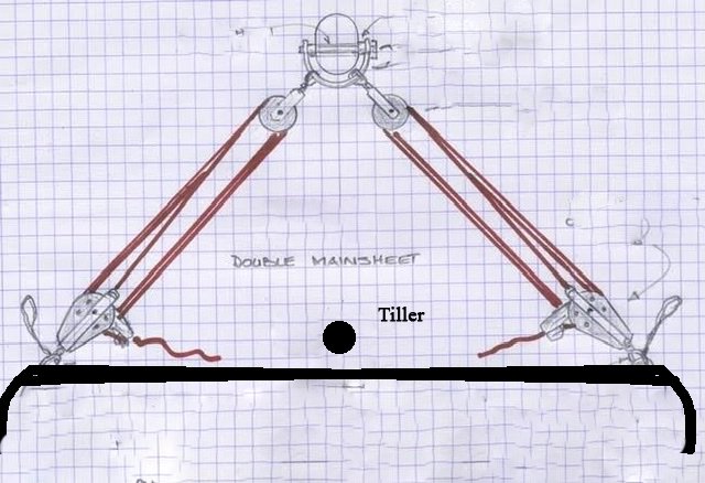
Strange indeed BE. On modern boats we usually use a traveler to which the mainsheet is attached and this sits forward of the tiller. On older boats which use a horse it is not uncommon for the horse to sit aft of the tiller. In which case the boat would be rigged with a double mainsheet like this. Maybe this was what was done but is not clear in th photographs
- 131 replies
-
- 1
-

-
- Medway Longboat
- Syren Ship Model Company
- (and 1 more)
-
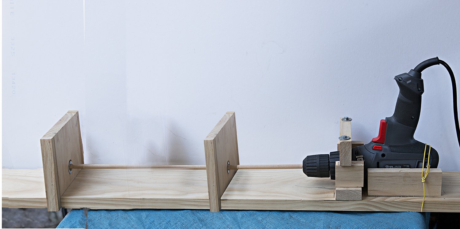
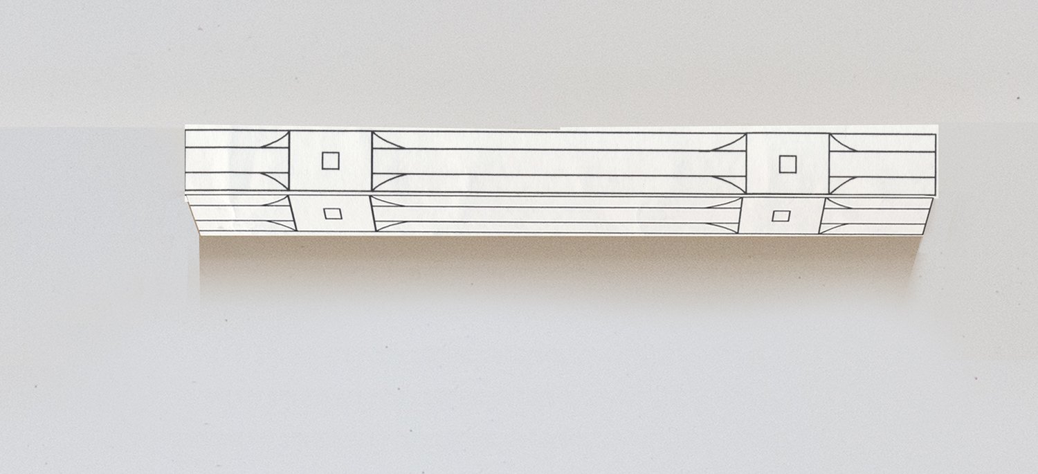
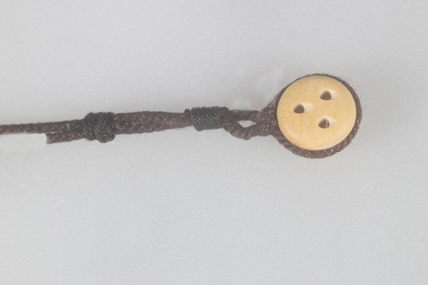
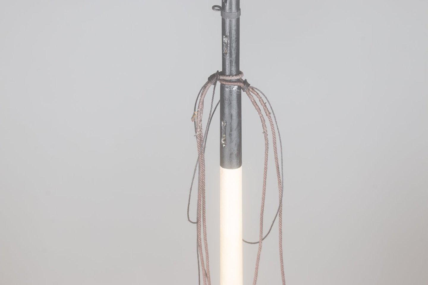
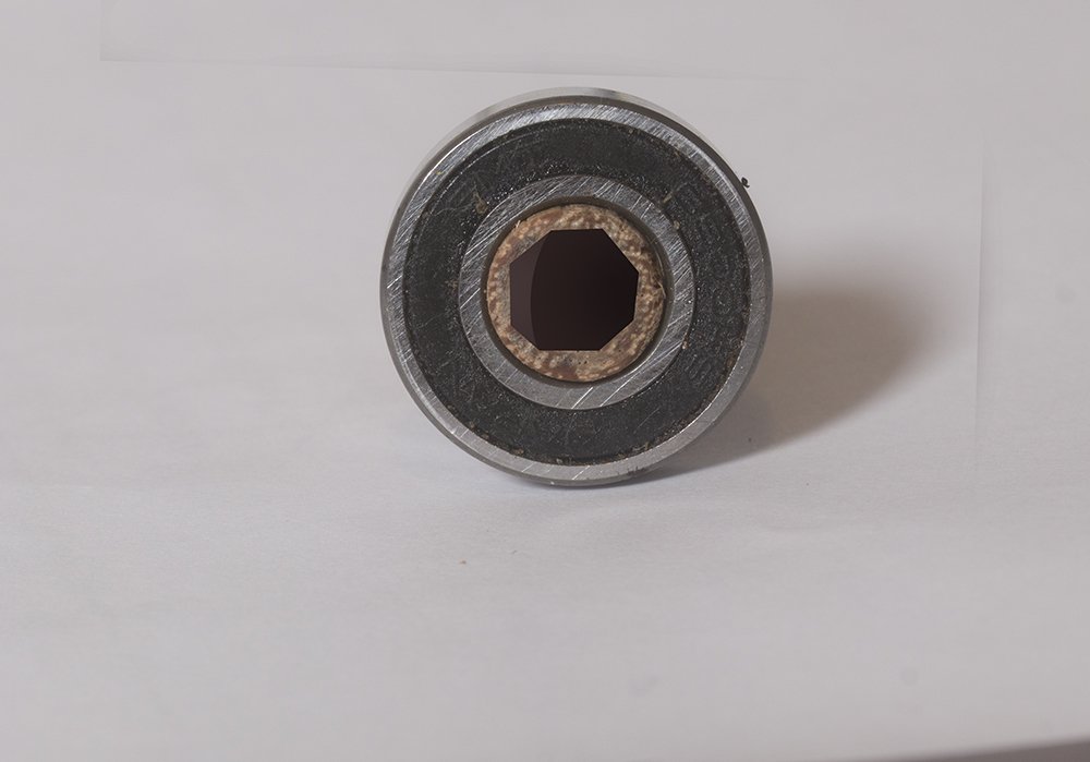
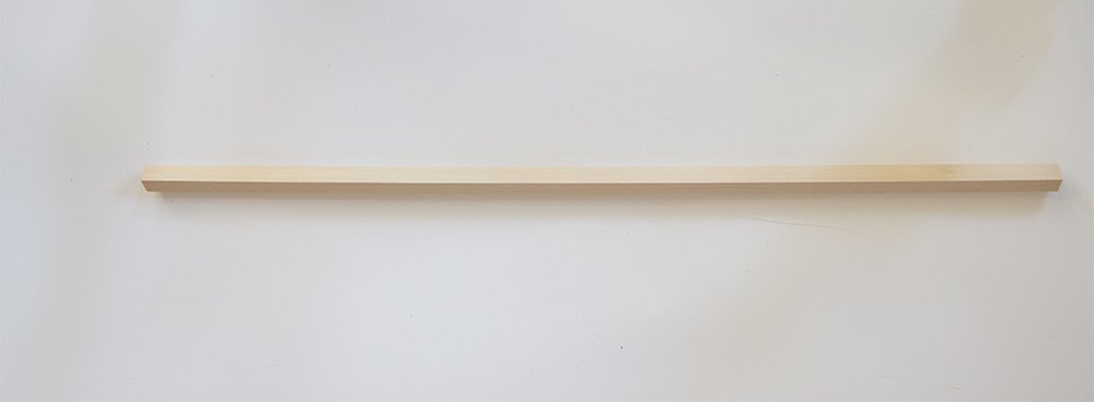
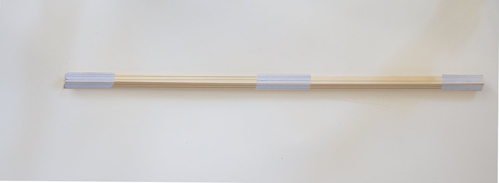
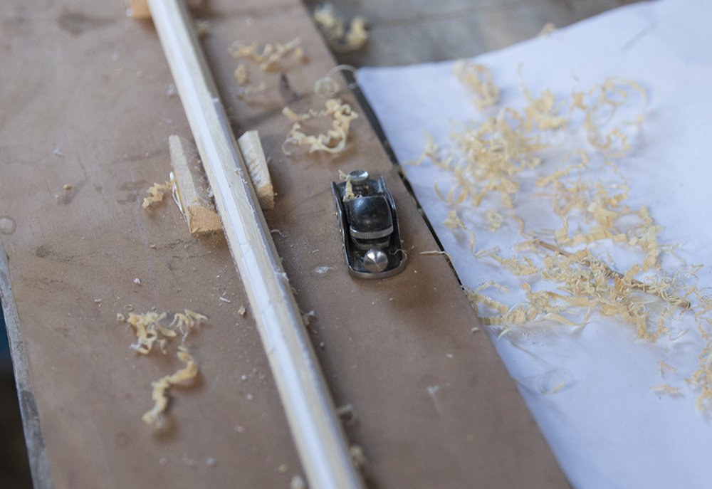
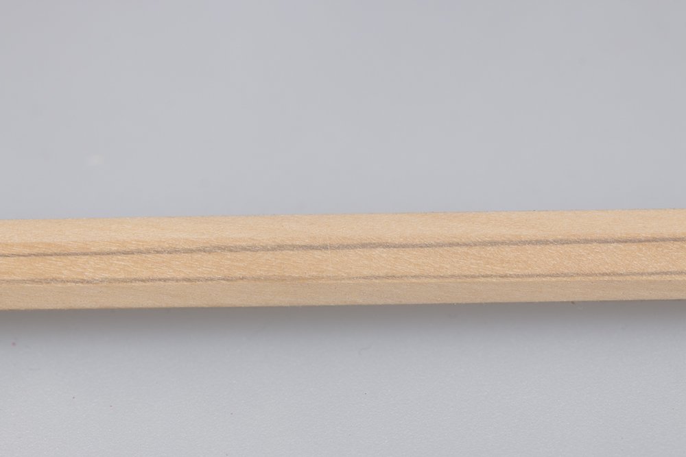
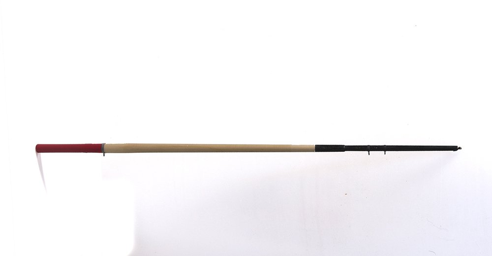
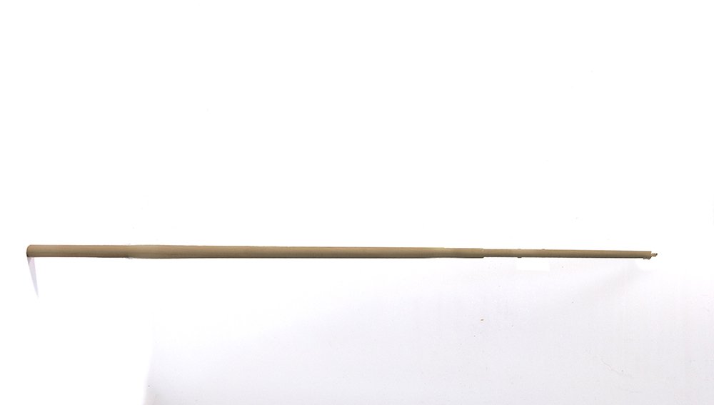
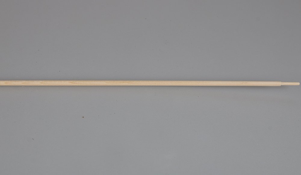
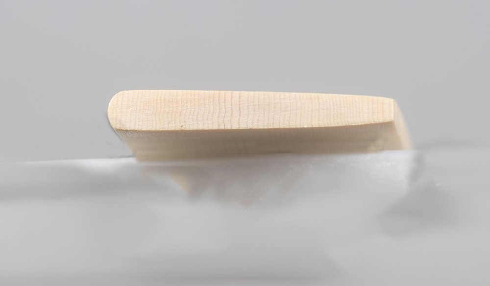
Fabricating the Mast The mast is turned from square stock which is first planed to an octagon using a 7:10:7 template provided by Chuck Yo can see that in this last shop a little more planing is required but I feel this is not critical. However it does help with the subsequent turning if the blank is symmetrical.. I use a home-built lathe to do the turning. This is not just to save a few dollars but believ that my version addresses some of the deficiencies I found using The Proxxon 250 owned by a colleague. These are: 1. even the slowest speed is two fast. 2. There is no steady support provded 3. Although this deficiency is claimed to be addressed by the hollow chuck, I found that specially for narrow spars, this caused a "whipping" which often shattered the spar motion which often shattered the spar. So in my version I use a variable speed electric drill and two moveable platforms. These align with the drill chuck and have a roller-skate bearing mounted in the center. If the spar is hexagonal or smaller diameter than the bearings, then wooden inserts are fitted. After here is the result after completing the turning And then after painting steel bands are simulated with black tape an eyebolds added as detailed in the plans John

-
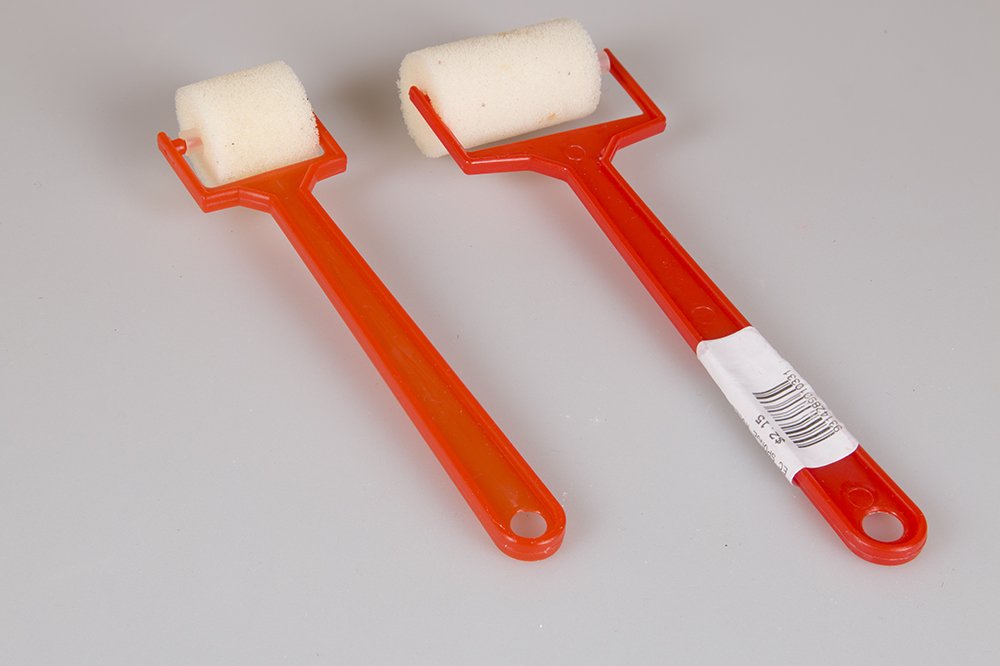
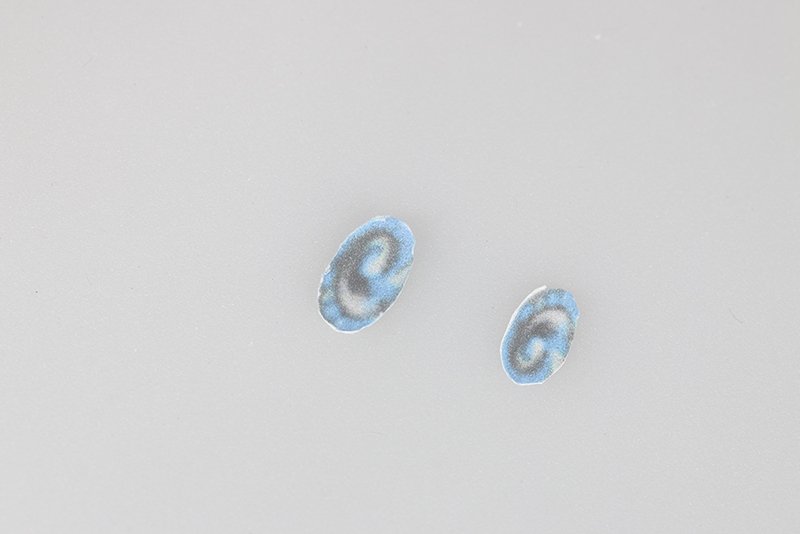
Yes, Tom, they are intended for applying glue or paint but the foam is quite stiff and I find that with a little pressure toward the perimeter of the sail the wrinkles are rolled out. The large one is about 40 mm and the small one about 20 mm . It may not work for everyone of course and you have much more experience than me on using your fingers. Regards, John
-
I have found that these little foam rollers help the wrinkles issue enormously You can lift a corner and gently roll towards that. Any remaining wrinkles can be rolled out towards the edges Incidentally I also found that if you spent too much time brushing glue on the sail, tiny pieces of silkspan detach and cause tiny bumps on the next layer
-
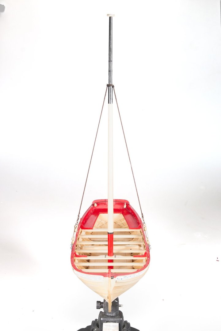
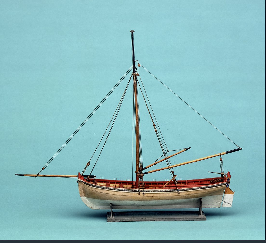
Yes I see what you mean now, BE, The whole issue of the must is hard to fathom. Its too big to carry on the lonboat. It must have been held on the sister ship only only installed if there was sufficient wind. As you say the deadeyes are simply hooked to the chainplate. I have never seen this before either
- 131 replies
-
- 1
-
-
- Medway Longboat
- Syren Ship Model Company
- (and 1 more)
-
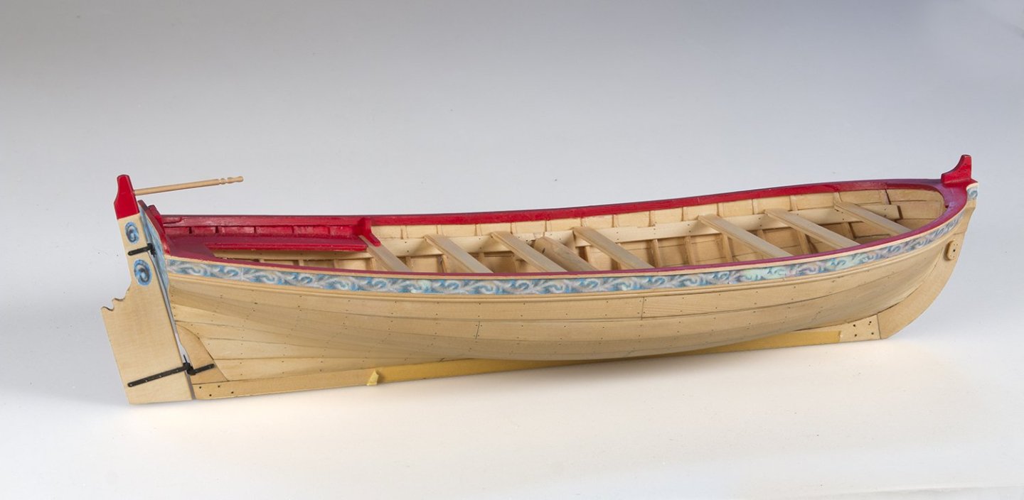
BE, This rigged version is also in the NMM and as you suspect it shows the deadeye straps mounted on the wales. Regards, John
- 131 replies
-
- 4
-
-
- Medway Longboat
- Syren Ship Model Company
- (and 1 more)
-
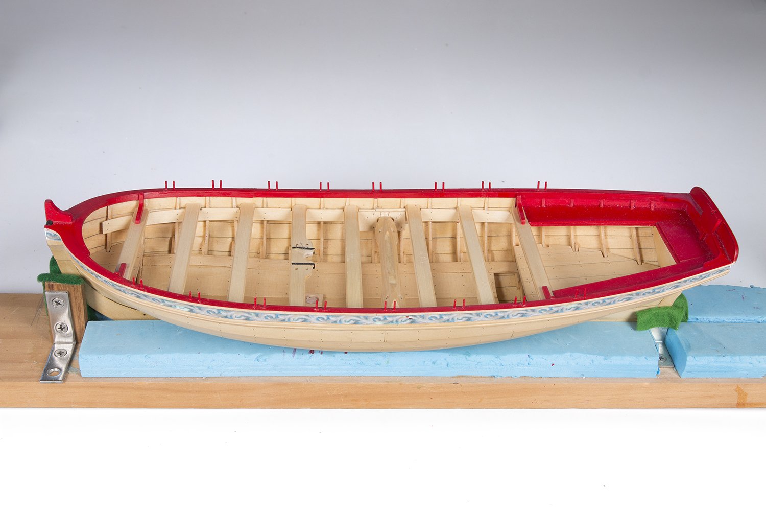
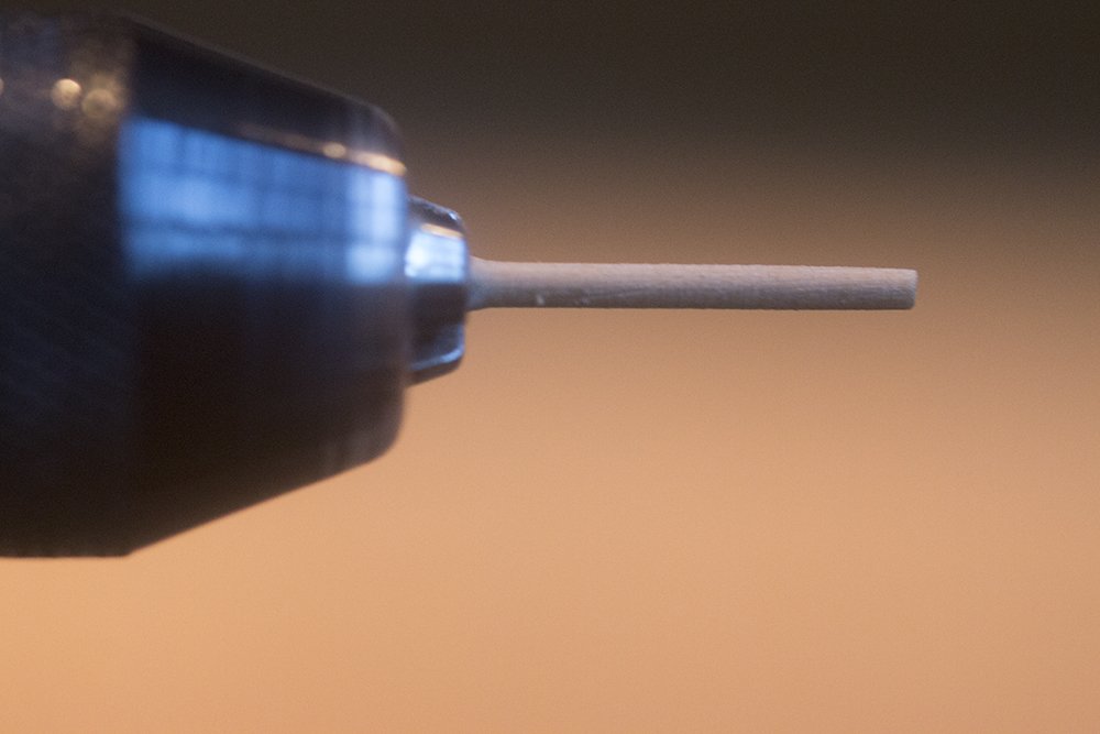
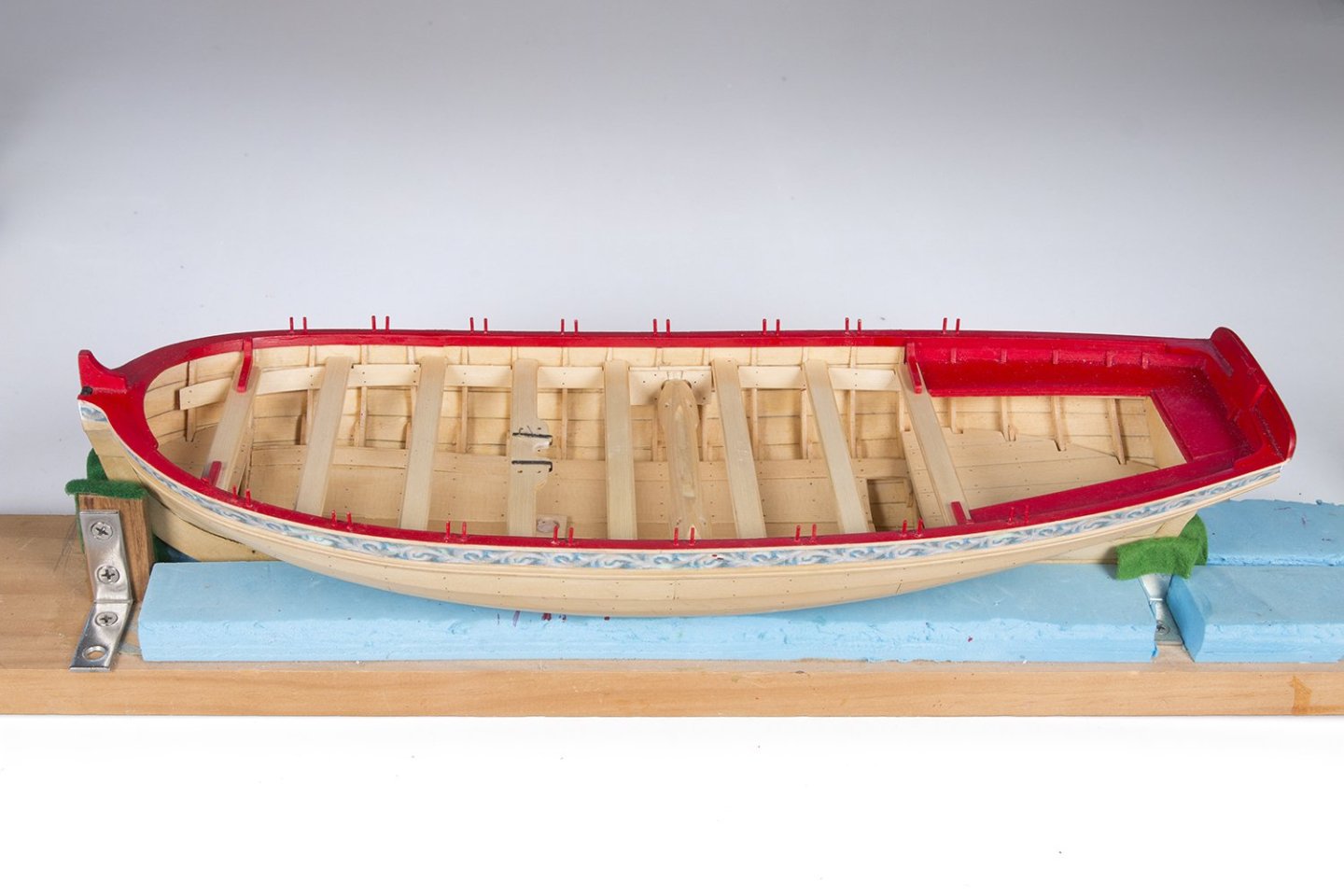
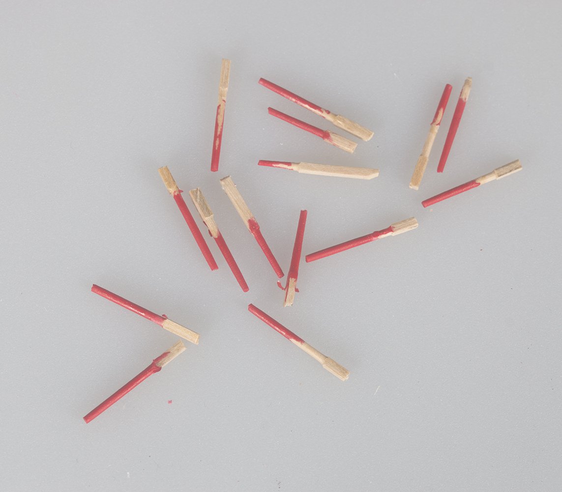
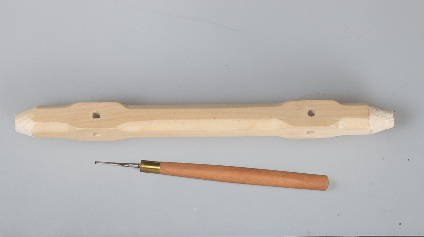
Thole Pins This was quite a laborious task - 32 identical pins required. I made at least 40. I turned them using my Proxxon rotary tool to a little less than 1mm: and them painted them red before installing so that I did not over paint the cap rail I.also found them more tricky to install than you might expect since the slightest impact would break them off. I used this jig to ensure that the spacing an height of each pair was identical I finally managed to get 32 in place and I am hoping that I don't break a few more off during rigging! John
-
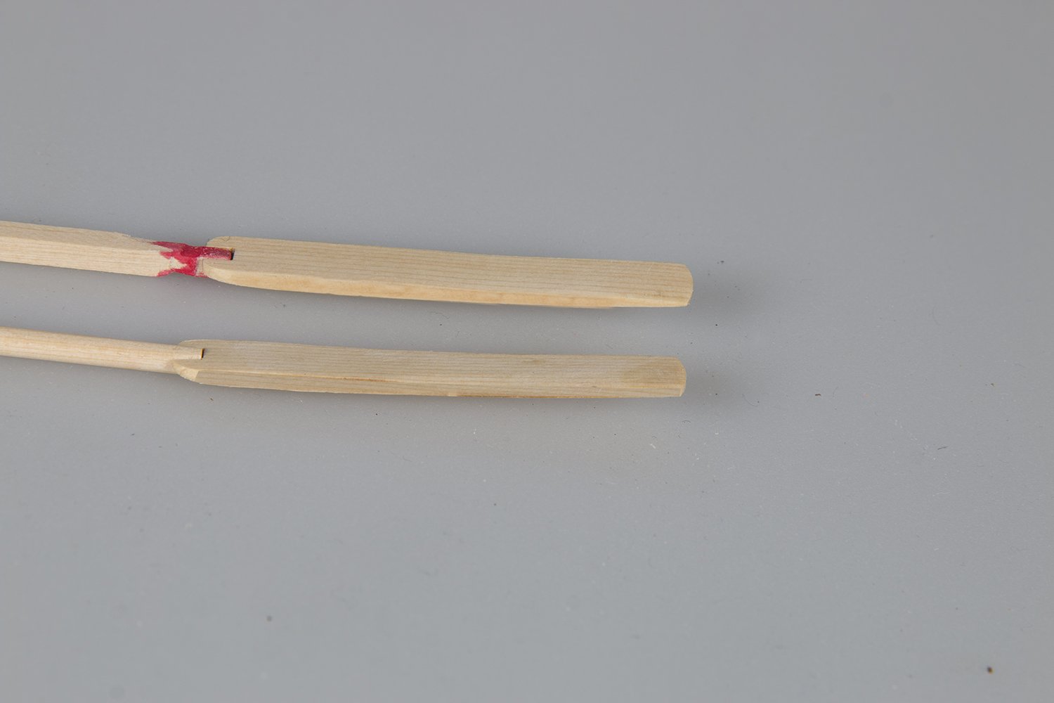
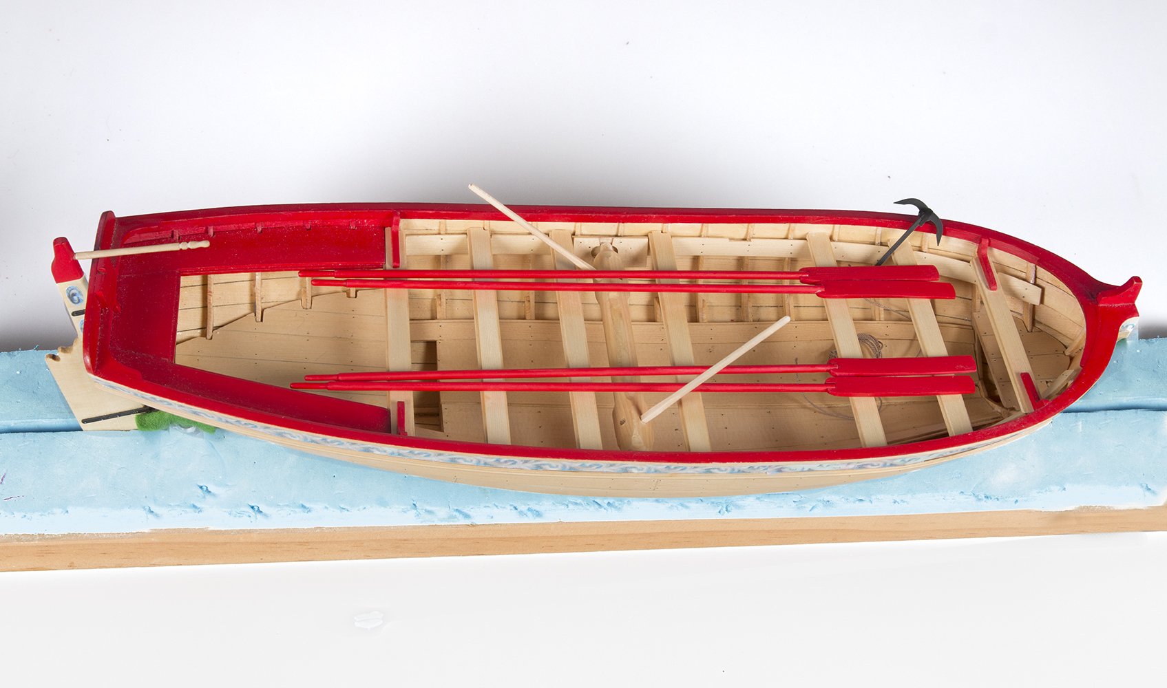
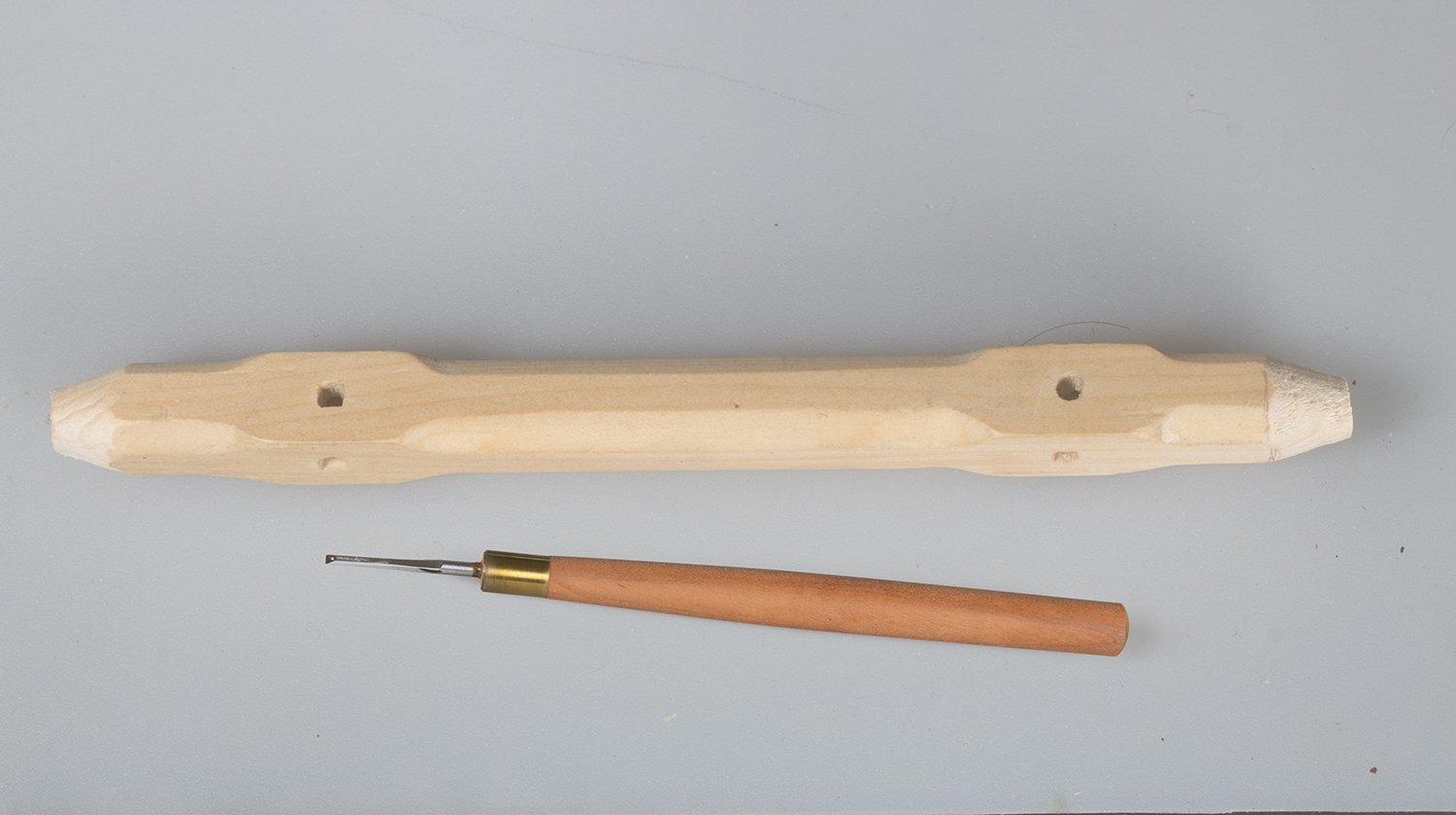
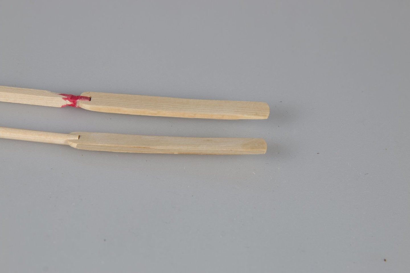
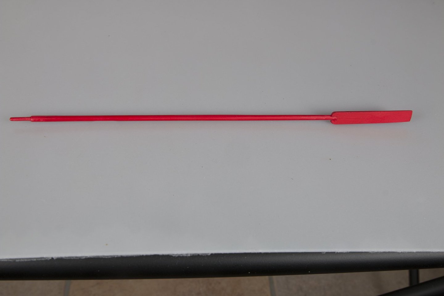
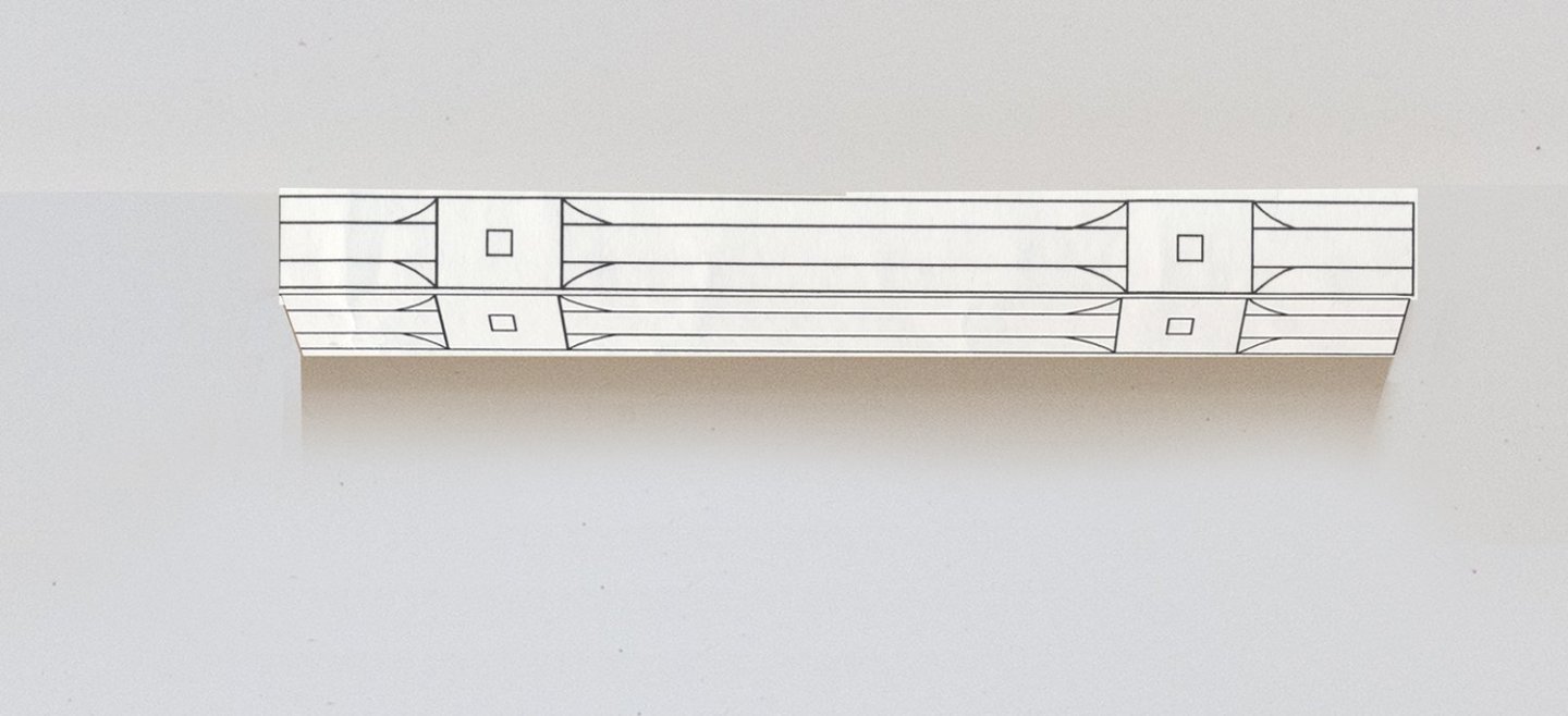
Fabrication of Oars Before starting on the masts and spars I decided to start work on the oars. This consist of a turned handle attached to the blades, I turned the handle on my home-made lathe The lades are laser cut from flat sheet. I standard these to obtain a slight curve which tapered toward the end And the final appearance of a single oar: I made only four of the eight or so that would have been used: John

-
Tom, I know this is a while ago but when you made furled sails for the longboat you seemed to have reduced the height of the main by about 50% Is this correct? And do you dye the silkspan, or leve it natural? Thanks, John
-
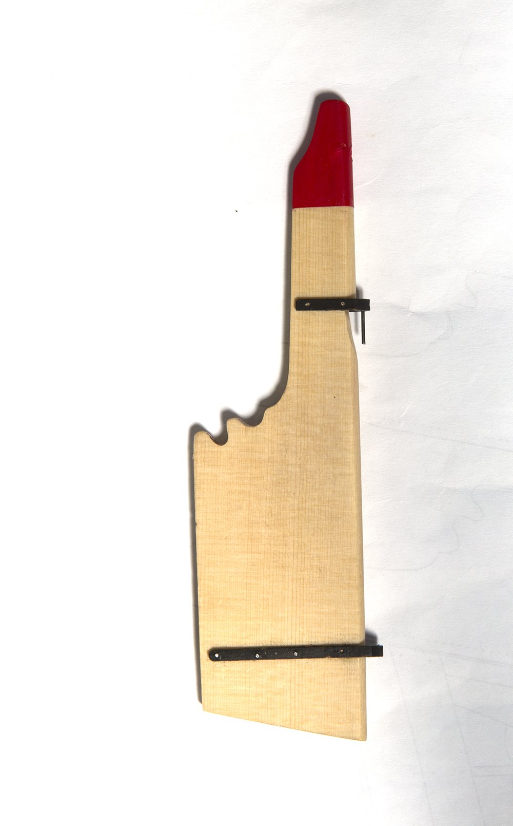
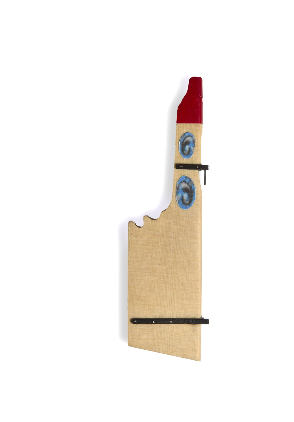
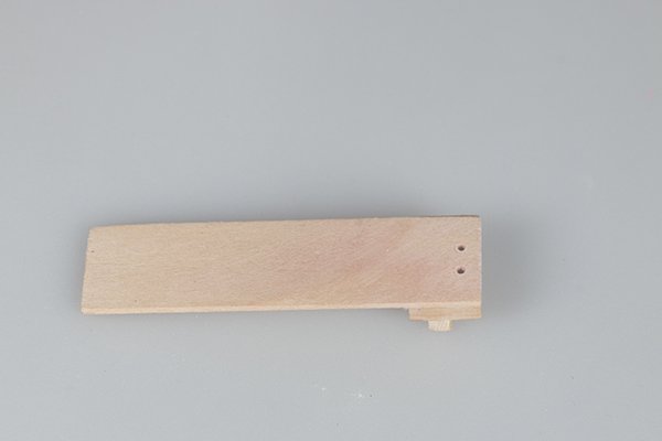
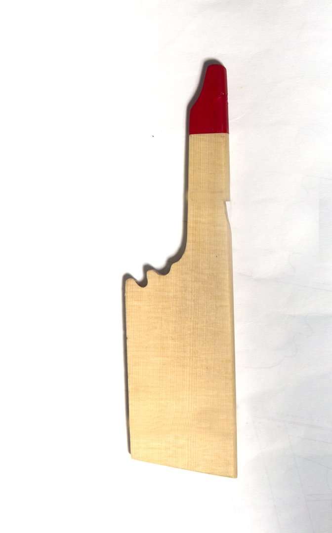
The Windlass and remaining thwarts Chuck provides templates for the construction of the windlass and these are glued to a piece of 3/8 X 3/8 square stock and the sides pared away to the lines A small chisel was used to make the pre-drilled round holes square to take the bars The windlass is then mounted into the model via the two small laser cut brackets wich are mounted below the risers. After installing thee more thwatrs thwarts the model looks like this:- Thw rudder was fabricated ftom the blank supplied. It was first standed to a tapered profile for and aft and rounded on the forward edge: After sanding smooth and given a coat of wipe-on Poly the top was painted red as shown in the The hinges were the added at the angle specified in the plan. These are laser cut boxwood and are quite delicate until glued in place. The bolts were simulated with blackened wire Decorations were cut from paper These are installed to finish the ruder After mounting matching hinges on the aft section of the hull the rudder could be mounted


-
How to make signs to identify models on display?
bartley replied to Dan Poirier's topic in Wood ship model kits
In my part of the world (Australia) companies who make sporting trophys will print text and/or graphic onto a brass plate. They usually require a vector graphics file which you can generate in Photoshop or Illustrator amongst others. -
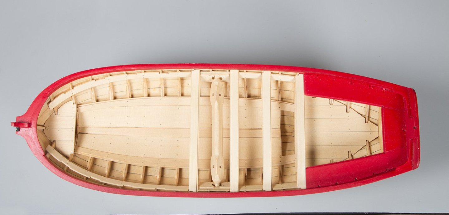
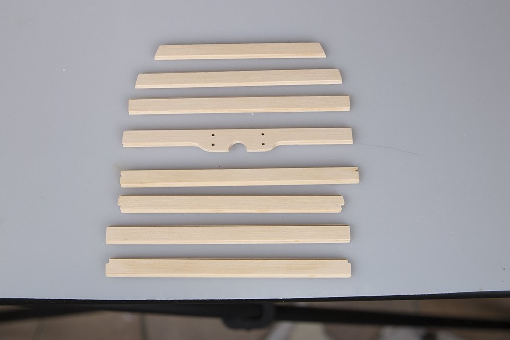
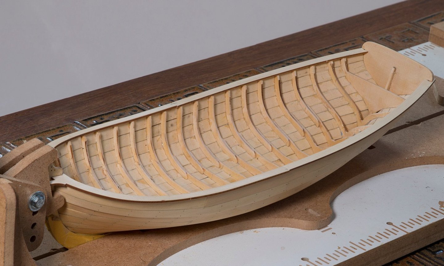
Thwarts and stern seats The first step is to fit the risers. There is a for and aft part and the by pre-bending these to fit the inner part of the hull they fitted well. The main issue is to make sure that the port and starpoard risers are at the same height. By measuring the height from the plans I found this fairly easy: The next task was to fit the thwarts and the cockpit seats. All of these parts are in two pieces. As Chuck points out, it is difficult to rebate a nice even edge particularly in AYC so all of these parts consist of a thick wide part with a thin narrower one glued on top. For example here are the thwarts: And the Cockpit seats ( only dry fitted here) The side cockpit seats are painted red: and finally the crosspiece an the Knees are fitted: Next up is to fit the rest of the thwarts permanently. John
-
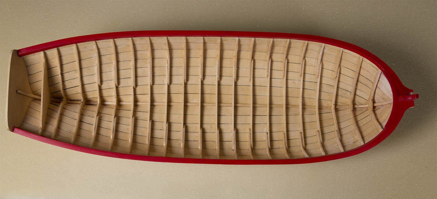
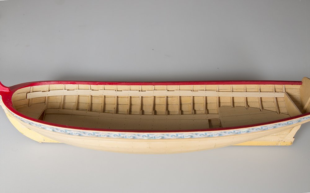
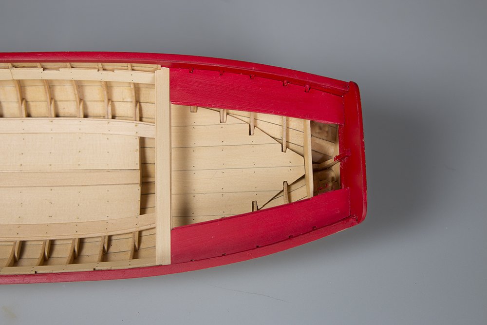
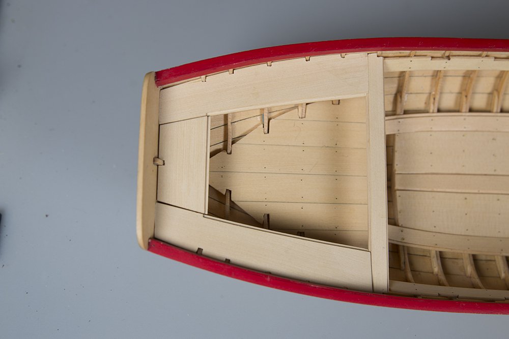
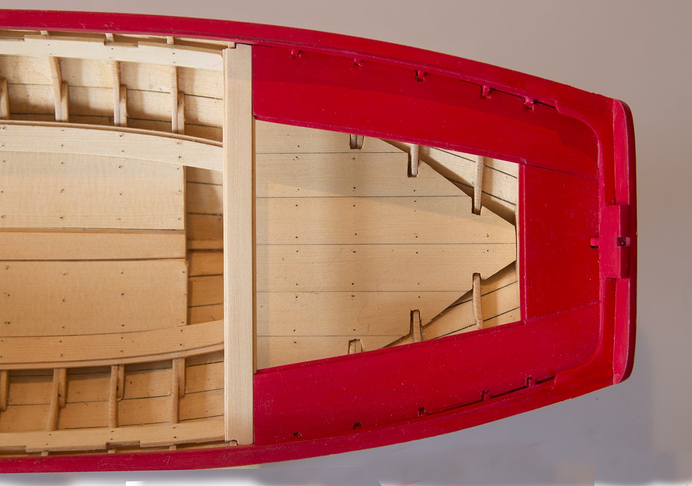
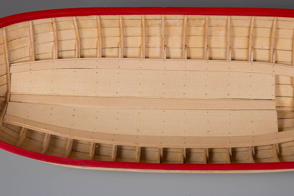
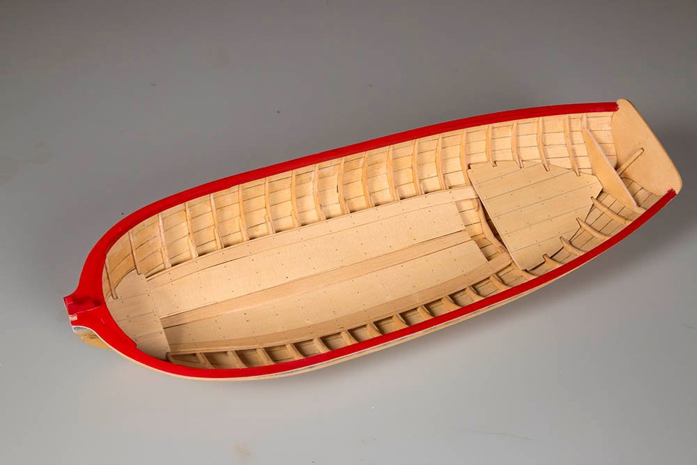
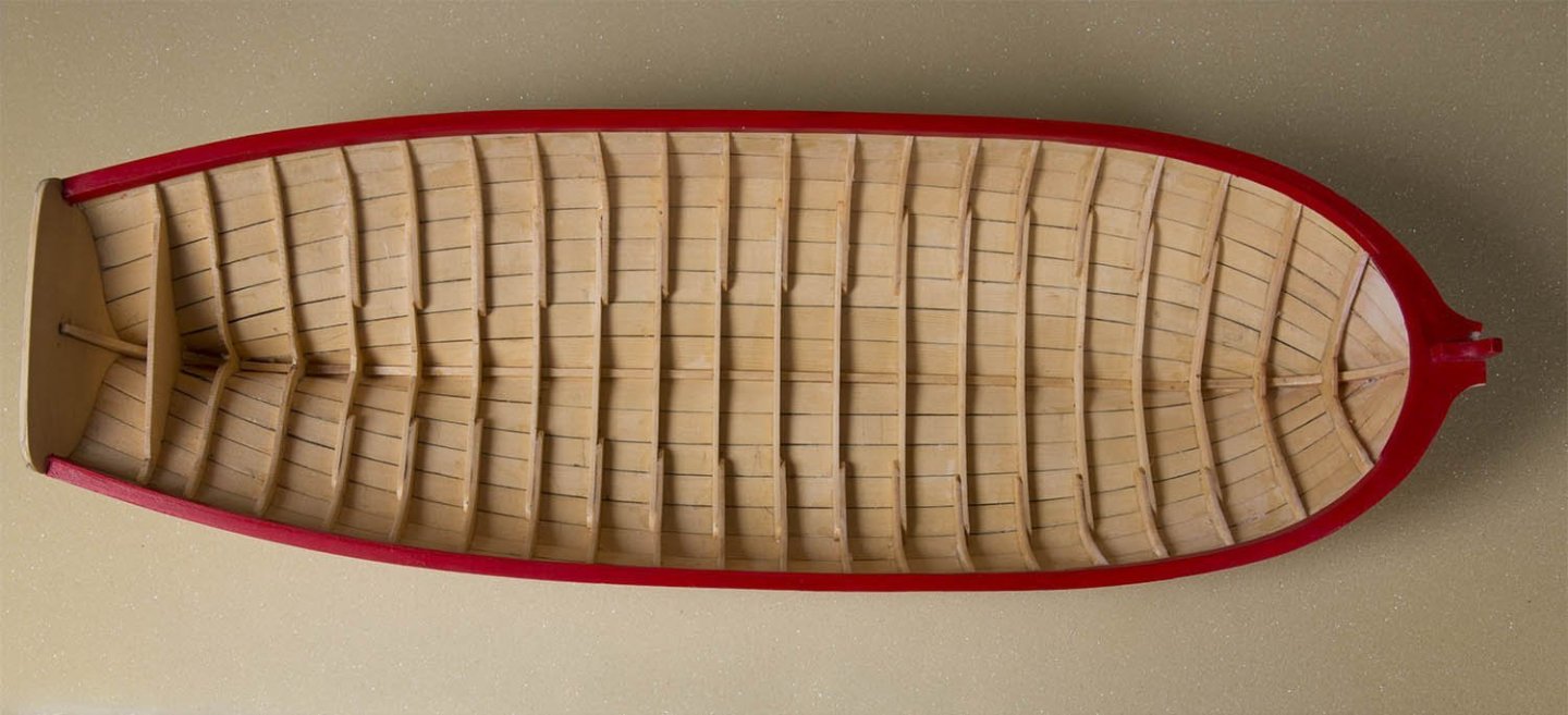
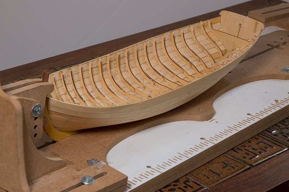
Flooring and Platforms I found both these steps quite challenging .The flooring has to bend over the frames of course and notching the platforms neatly was also challenging. They are still not perfect but as good as I can get them. John
-
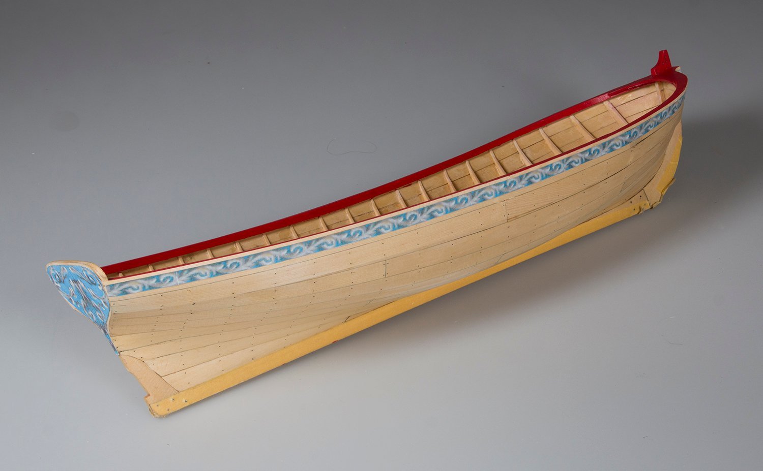
Finishing the Cap rails After thinning down the Cap rails to around 5/32, the inboard strake added. They were painted red and the friezes attached

-
drilling hole through wire
bartley replied to BETAQDAVE's topic in Metal Work, Soldering and Metal Fittings
I have done this on 2 mm brass rod with a good success rate. My technique was: 1. I used a mill to ensure the hole was vertical. 2, I used a V bar and centered the drill bit on the V before clamping the rod into the V 3. I used a Kyocera bit as they a very sharp 4. You can file a very small flat on the side where the drill will enter but I did not find this necessary. John -
Stepping the mast with a plum bob...two questions.
bartley replied to HardeeHarHar's topic in Masting, rigging and sails
I agree with those who say not to glue the mast at all. However, in most cases there is quite a deep slot cut into the bulkhead under the mast which should set the rake quite at least approximately,. As you tighten up the rigging you still need to check th alignment I used to use a plumb bob but always found this a real PIA as it starts to swing on the slightest movement. I now use a laser level (quite a cheap one). I set it up about 1 m from the ship and it does NOT move and it projects a cross so that you can adjust the deck to match the horizontal line and the mast to match the vertical line. For the rake you can use a jig to tilt the ship forward by the correct amount and use the laser level again. John -
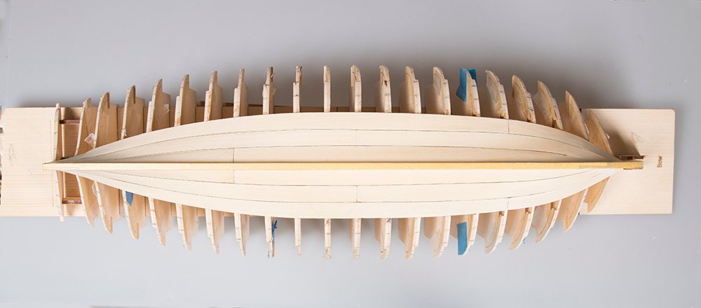
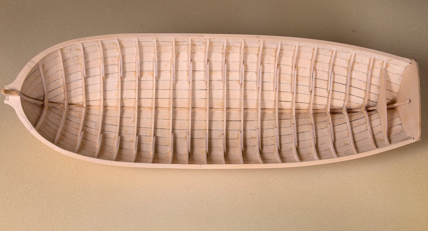
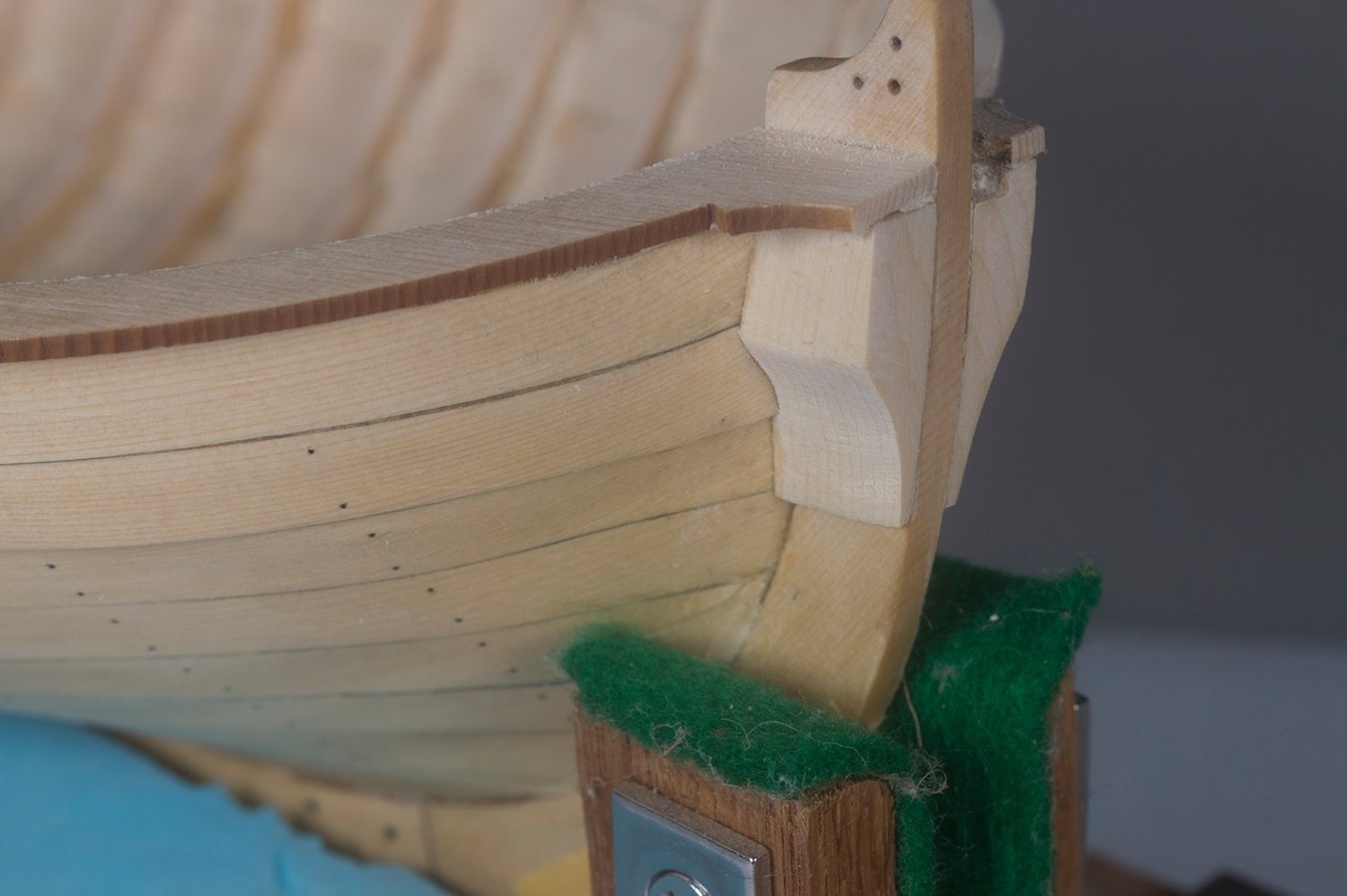
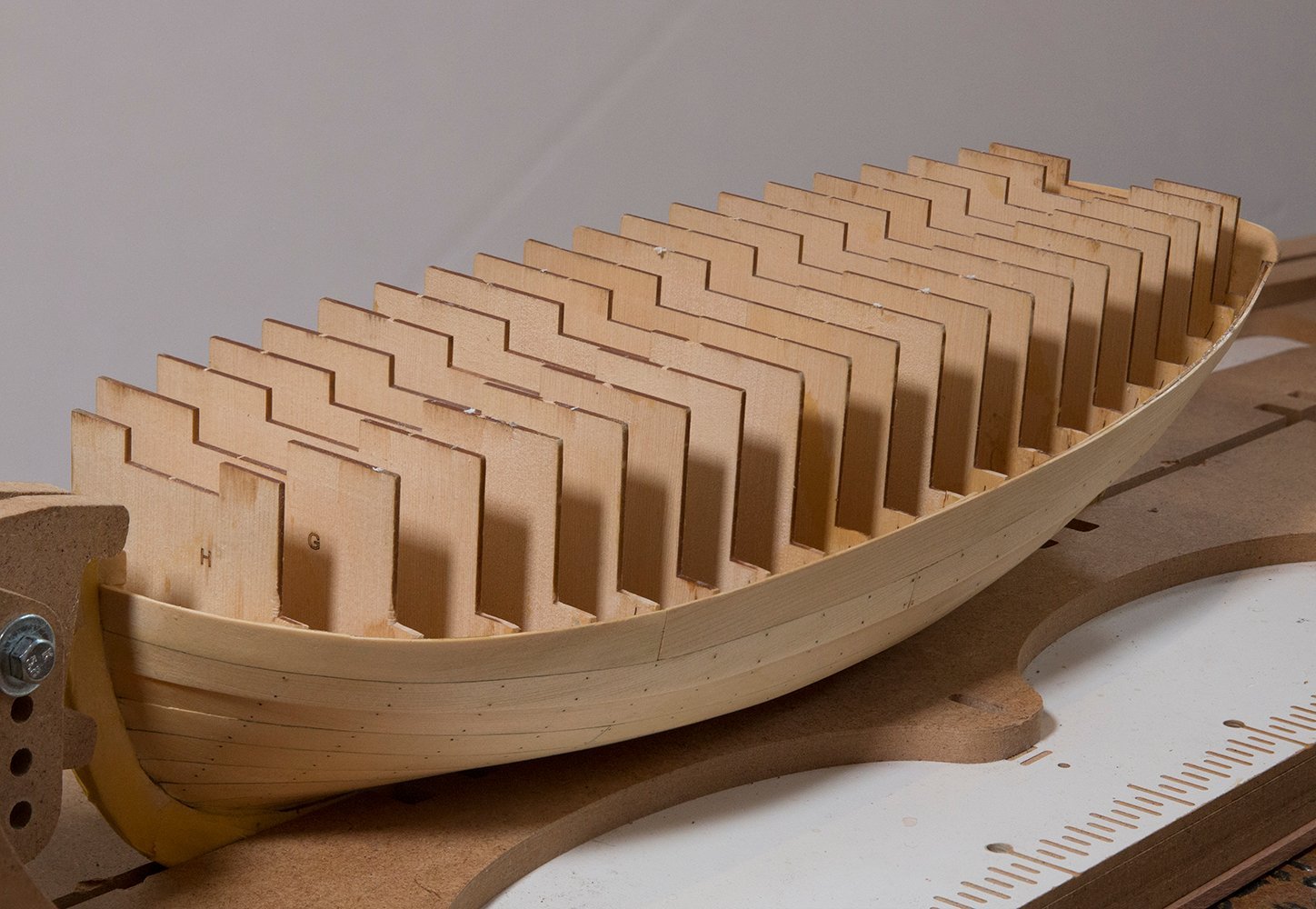
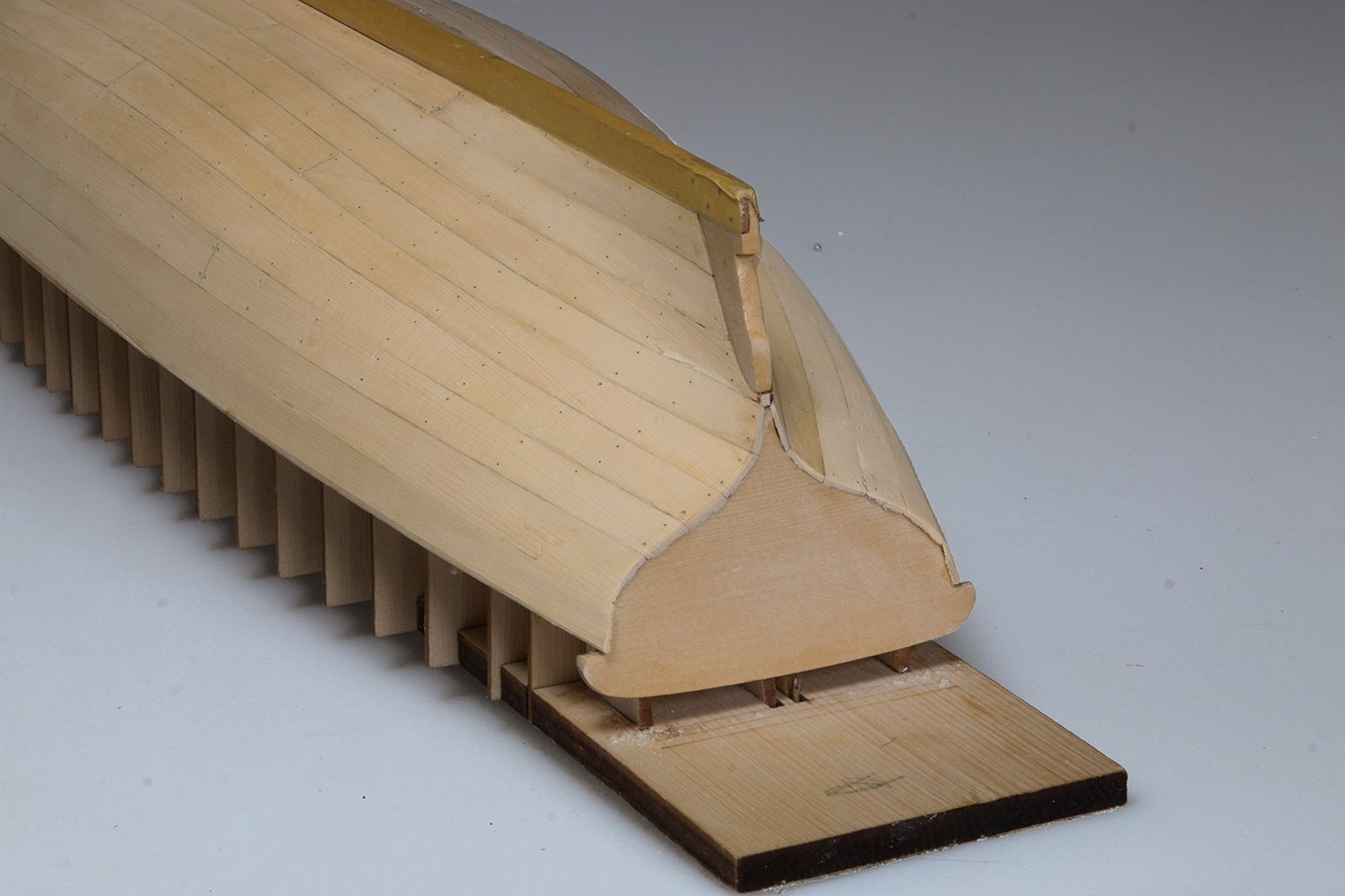
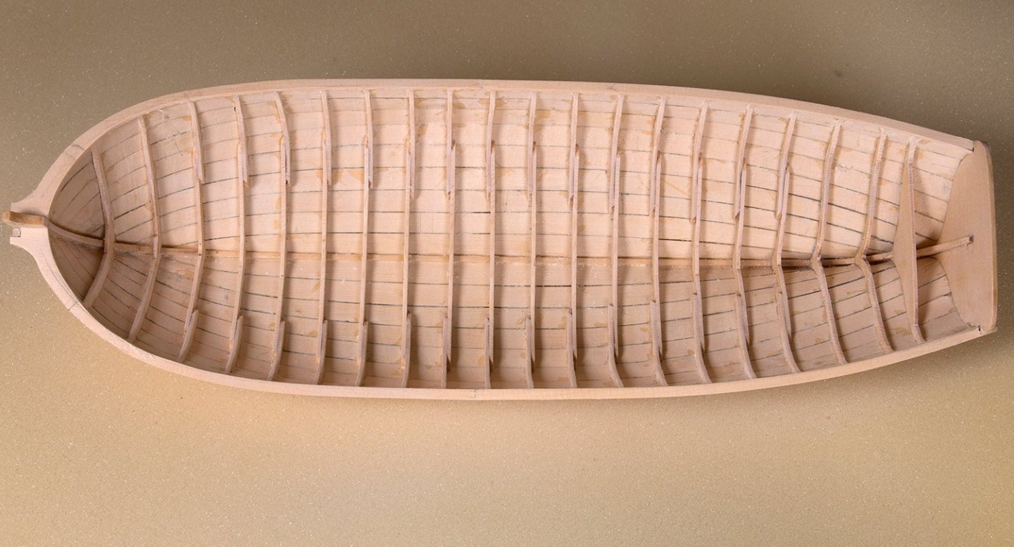
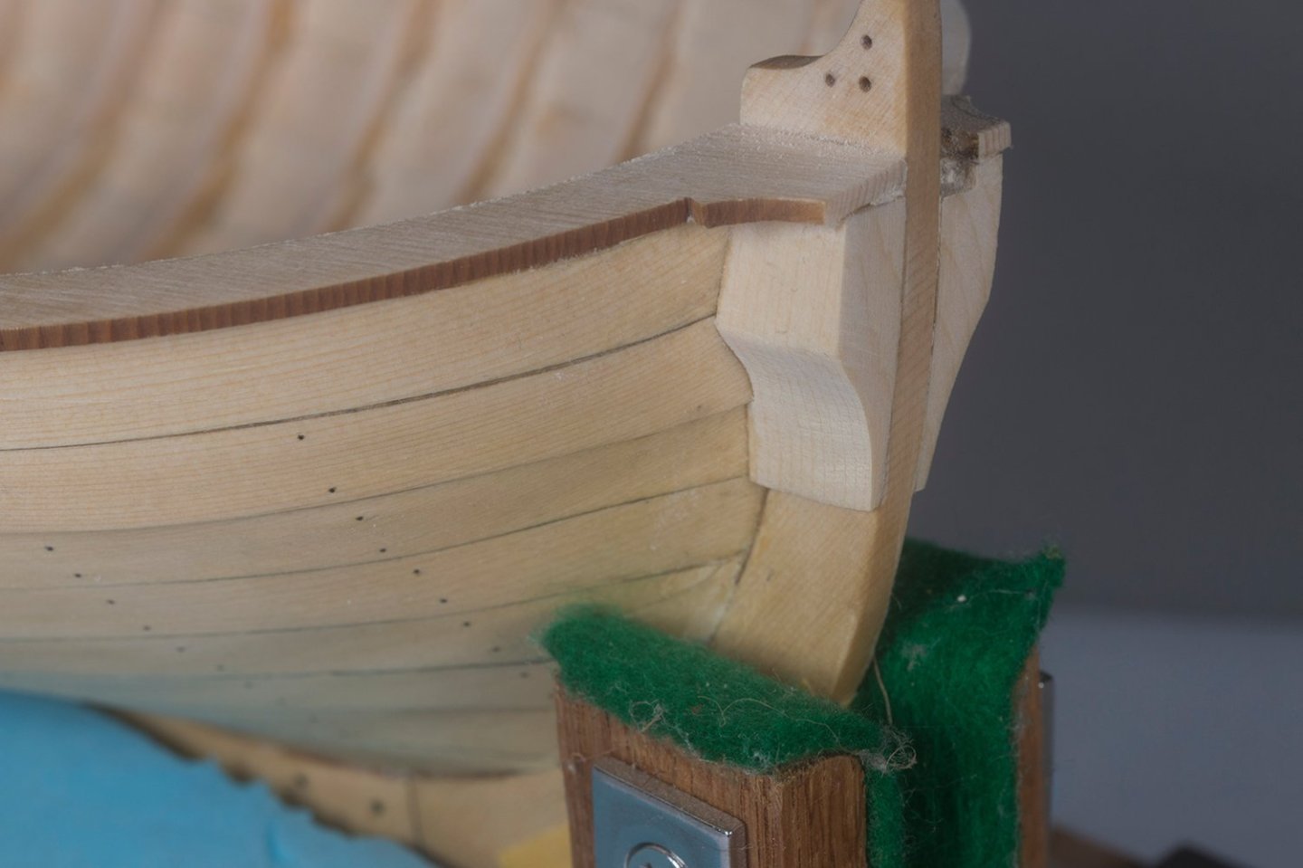
The Wales are now installed and sanded back for and aft as recommended by Chuck.: When the hull is inverted and the build board removed it looks like this: The removal of the frames was quite straightforward . However there is way too much seepage of glue into the interior of the hull . This is the first time I have used CA to fix the planks. I clearly overdid it. I was a little unsure about the faring and wanted to ensure that the planks were secure. I needn't have worried as the fit was pretty good in fact. The cap rails were then installed leaving plenty of meat on either side for sanding to shape: Next the bolsters at the bow were fabricated and fitted. A tricky little job this one. Chuck provides six blanks and I used five to get two satisfactory ones: The next task is to fair the inside and narrow down the cap rails significantly. John

-
Thanks for your support, Rick
-
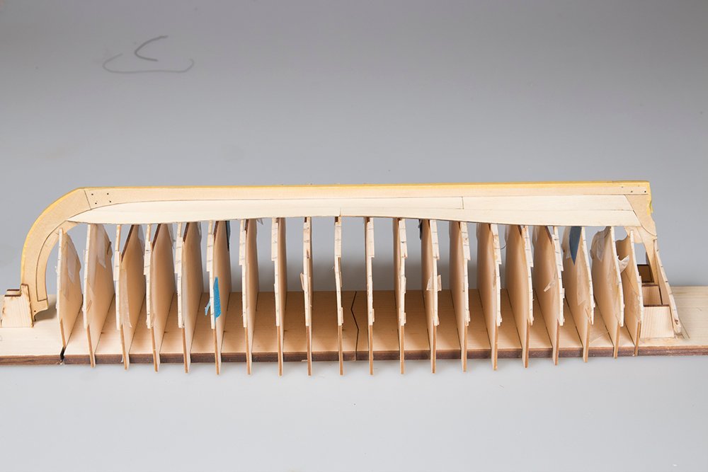
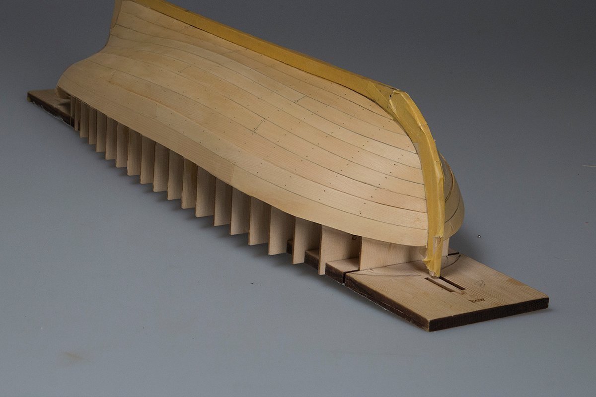
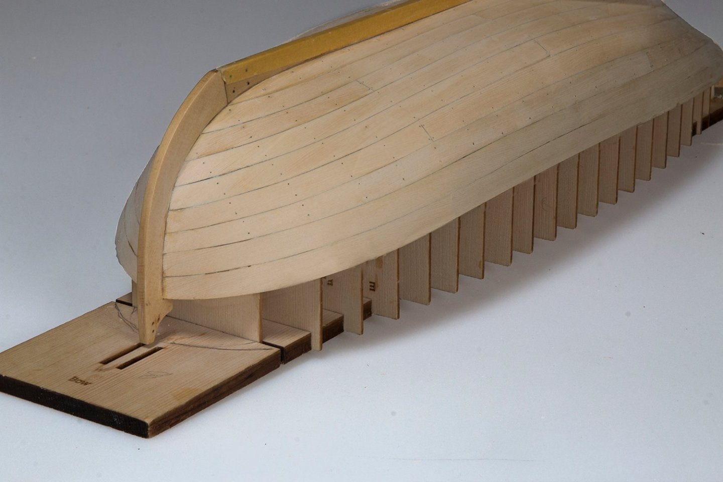
Planking completed I have all nine planks on now but the wales are still to be installed. It looks a bit "blotchy" because I gave the first five planks a coat of Wipe On Poly and when I sanded back some of it remained. It will be more uniform when I apply I final coat I am also a bit shy of the top of the frames amidships (by a little under 1/32). I could see that this was happening throughout the planking. I think maybe I did not fare quite enough in this region. Anyway I was proposing to address it by making a slightly wider second Wale John

-
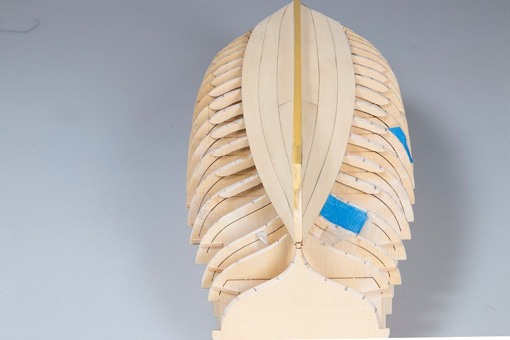
Planking begins: I have three strakes in place now. I damaged the end of one garboard and had to make a new one. Mine was not quite the same as Chuck's laser cut one so the was a little asymmetry between the sides but I think I am pretty close to my tick marks now so I am reasonably happy but it is nowhere near the quality of Chuck's high standard. I am thinking that I might start the simulated nails now while I can see the frames clearly. Would I need to do light sand before attempting this? The planks are pretty thin so care would be needed. What to do people think? John