Modeler12
-
Posts
1,716 -
Joined
-
Last visited
Content Type
Profiles
Forums
Gallery
Events
Everything posted by Modeler12
-
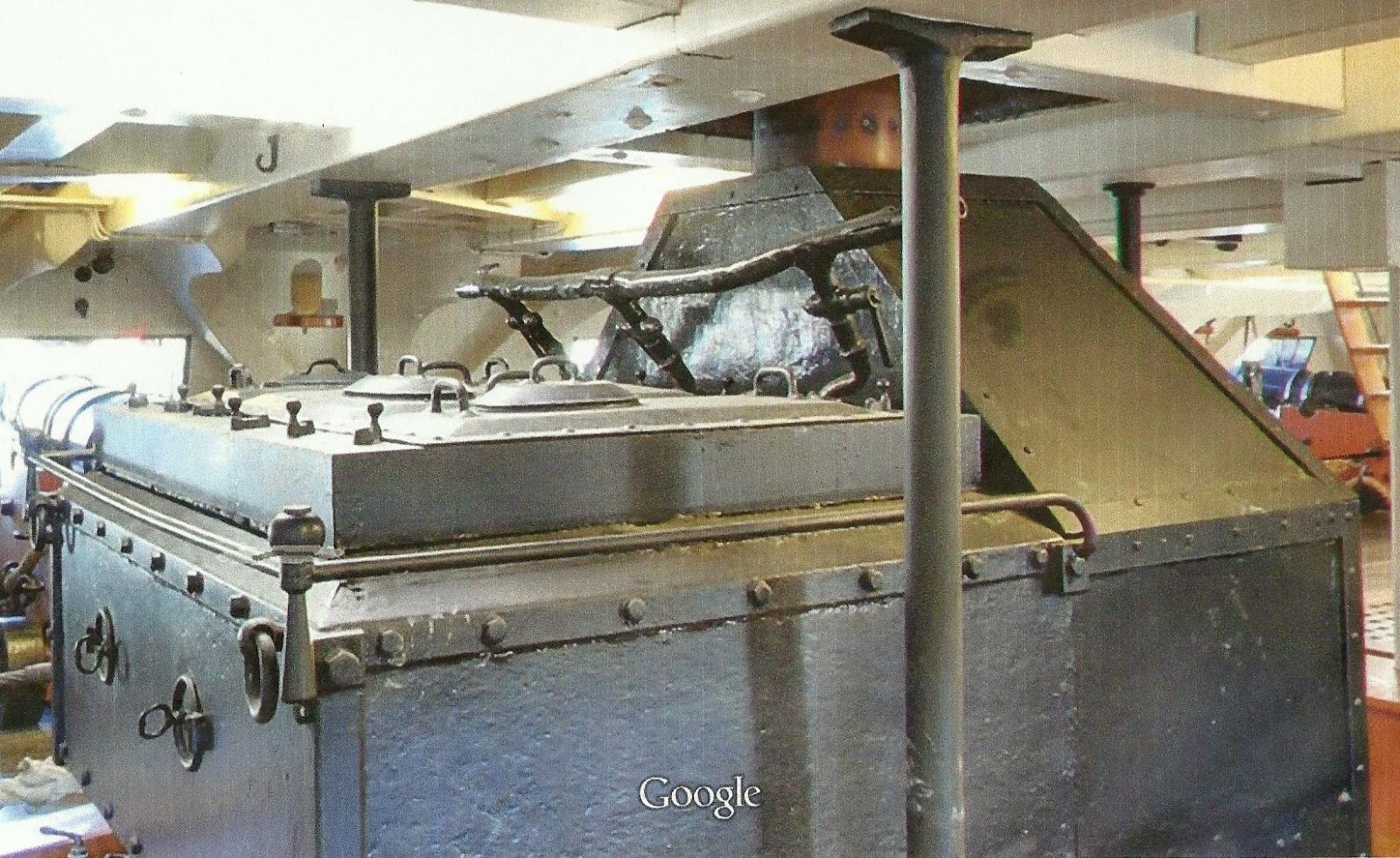
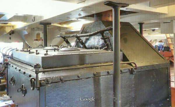
 It depends on what you consider the front of (what I call) the stove. The view in the picture was taken looking aft. This is the area of the stove that had the boiling pots that served most of the crew. This must have been a very busy area during mess. I, in this log, am starting at beam 11 looking towards the bow and call this view of the stove 'the front'. PS I am curious why you call this a 'camboose'.
- 572 replies
-
- 3
-

-
- constitution
- frigate
- (and 1 more)
-
The grates are not that heavy. Henry apparently had no problem. I agree that those nicely made keepers are surely new. And the whole thing is not related to any of the electronics, lights, switches, and safety alarms. But perhaps it is some kind of protection for foreign visitors to indicate that this is not a place like you find in China.
- 572 replies
-
- 3
-
-
- constitution
- frigate
- (and 1 more)
-
I have tried to send a private message to Wayne, but apparently he does not want to receive those. The message has to do with the fact that I changed my mind about the Navy drawings and I am using them to create my own. Nothing earth shaking, but I would like to communicate with Wayne unless he feels differently. So, Wayne, send me a reply, please.
- 572 replies
-
- 3
-
-
- constitution
- frigate
- (and 1 more)
-
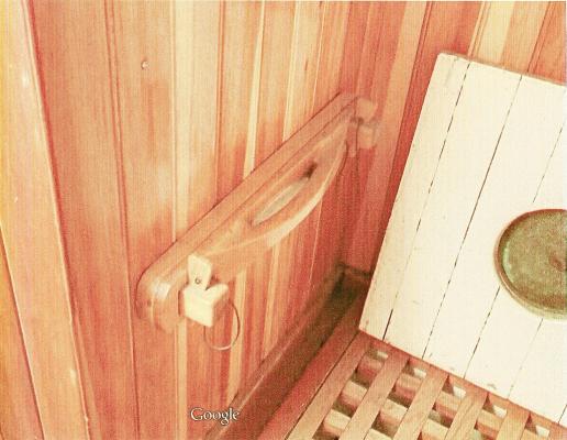
Dan, no TV, no beer, no fun. Where do you get all those drawings? The CD you mentioned? Here is another puzzle for you, Henry and everyone else: Next to the mysterious hatches on the orlop deck going down into the dungeons, is a nicely carved, wooden 'something or another'. It is not a handle and to me it looks like part of a sheave with two holes for rope. What is it and what is it doing where it is? Notice the cloth covering the hole in the hatch. It is just like I saw in that cartoon Jonathan showed us. Notice also the Google name on the bottom of the picture. I hope hereby that Google will agree that these copies are for a good cause and will not be used for commercial purposes. That goes for all of the copies I show that were taken by their cameras. I also assume that Google got permission to do all of that and make the results available to the museum and/or National Park Services. Do I need to expand? Any lawyers out there?
- 572 replies
-
- 4
-
-
- constitution
- frigate
- (and 1 more)
-
I bet you are right, Henry. The drawings that Dan supplied me about the fresh water lines (and pump) showed that there was a lead pipe going all the way to the oven. I also have this picture that shows the valves on top of the stove and the cut-off end. On my stove model I only show two kettles but that will have to stay (my mistake).
- 572 replies
-
- 4
-
-
- constitution
- frigate
- (and 1 more)
-
You know that little 'fill room' down there would be a perfect hideout for a ghost or two. Maybe you can start a rumor: 'The Constitution Ghost continues to dwell among the gun powder kegs waiting for the right time'.
- 572 replies
-
- 6
-
-
- constitution
- frigate
- (and 1 more)
-
I can just imagine, Henry, you lying there on the deck all decked out in an 1812 uniform with your head into the hole. Some one coming by would have been scared to death. You're a real gem.
- 572 replies
-
- 4
-
-
- constitution
- frigate
- (and 1 more)
-
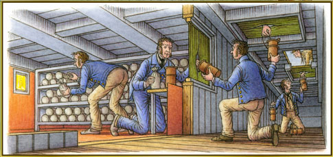
Thanks Henry. Then the sketch that Jonathan provided me makes more sense. There is a wall with a door through which the fellow inside the magazine would pass the pouches etc. Man, that must have been a very tight squeeze. Just one more question (I am sorry to bother you so much). The drawing above shows both scuttles with men passing the pouches up. Did it look like there was a wall between the two and could you see any posts at the center line of the ship. I understand now that you could see the metal tanks looking aft, but now I am curious what you could see looking towards the center of the ship.
- 572 replies
-
- 4
-
-
- constitution
- frigate
- (and 1 more)
-
George, I fully agree with you regarding the confusion of Navy drawings (or lack thereof). Here is my assessment and I will leave it at that. The 1819 Ware Plan drawings were probably the first set of details showing the plan view of the orlop deck but no cross section, no side view. There was no mention of a powder room or magazine below the deck. Marquardt’s book on page 49 shows a detailed layout of all decks including a powder/fill room below the orlop deck. It also shows a light room with ladder going down. I used that for my first orlop deck, but now doubt about anything is see here (wrong locations, etc). Then on page 57 same book, he shows a new side view marked ‘Twentieth Century Restoration Drawings’. All of a sudden the bottom of the main mast goes from six feet above the bottom of the ship to eight feet. Without any explanation most of the keelson grew by two feet or so. This created the low overhead below the orlop deck compared with earlier drawings!!?? The Navy Restoration drawing of 1926 shows a plan view of the orlop deck ‘with planking removed’. A note on this drawing mentioned that all of this was based on measurements taken on the ship. Did they really remove the planking to do this? However, the drawing does not show the keelsom nor any posts standing there. Perhaps some people crawled underneath the orlop deck (and perhaps not). I simply don’t trust that drawing. Why did it not include a side view or cross section view? Then there is the side view that Dan provided me from his CD. I was not able to zoom in on it, but it does show the way the area underneath the orlop deck as it is today. It even shows the two light boxes that Henry pointed out. Something the restoration drawing does not show. Finally there will be Jay’s drawings. But they will have to wait for a couple weeks to be published here.
- 572 replies
-
- 4
-
-
- constitution
- frigate
- (and 1 more)
-
Thank you George for your nice comments and all the times you have spent followed my folly. After I get back from the lake I will redo the orlop deck and continue like there were no mistakes made in the past. After all, some of our history is best forgotten if the records are sour.
- 572 replies
-
- 5
-
-
- constitution
- frigate
- (and 1 more)
-
Actually we are renting a house there that will sleep 14 people (they say). Between the 12 of us it should be 'fun' One of our son-in-laws has a large boat he is bringing and the other one is renting a 'party boat'. So we should have plenty to do if we can find water. If not, six grand kids will keep us 'entertained'.
- 572 replies
-
- 5
-
-
- constitution
- frigate
- (and 1 more)
-
Thank you Wayne (and every one else who contributed to this great adventure), but at this point I have to continue with my build. I have learned a lot from all of you and will continue to take advise as you may think appropriate, but right now let me refresh: 1. Marquardt's book leaves a lot to be desired when it comes to accuracy. It has caused me many headaches and lots of time spent correcting. 2. The drawings and Henry's pictures have helped me clarify several things about the Orlop deck (and what may be below it). 3. I am not trying to recreate the ship as it was built and don't care what it 'might have been like' without certainty. I like to see what she is now and perhaps a few years ago. The basic structure is there and a few changes in walls etc. will not change the whole ship. 4. My logic and instinct about the lower structure is good enough for me to draw up some plans and build that part as I see it now. 5. This is still my build log but if you wish to continue with details that are not part of what I am trying to do, I suggest to post those with a new thread. 6. I need a vacation and will be spending some time at Lake Shasta (CA) despite the low water levels and drought there. Are any ship models made exactly like it is supposed to be (or was)?
- 572 replies
-
- 6
-
-
- constitution
- frigate
- (and 1 more)
-
Mark that makes a lot of sense. In other words the barrels with powder could be stored in the aft magazine where the cartridges would be filled. Then they would transfer a lot of those cartridges to the forward 'magazine' where they would be stored until needed. Just like Jonathan's cartoon shows. The forward magazine would have no barrels. To transfer all those cartridges would require some special handling equipment, such as barrels (with copper hoops) that could be sealed. The picture that Jonathan shows would not be the aft but the forward magazine. All it shows are shelves with cartridges and the hatches correspond to that area, plus it depicts the hole in the scuttle the way it is now. My admiral was right: this is Jay's Mystery Ship
- 572 replies
-
- 4
-
-
- constitution
- frigate
- (and 1 more)
-
Yes it does Jonathan. It explains why there is no copper just below the hatch covers. A separate wall with the slit covered 'window'. HMMM. I wonder how the fill guys got out? But if this was aft, it is reasonable to assume that the same thing held for the forward fill rooms.
- 572 replies
-
- 2
-
-
- constitution
- frigate
- (and 1 more)
-
What that means, Wayne, is that the aft 'magazine/powder room' which was coppered per the photograph above was indeed both a fill and storage area. Do we know that as a fact? I think that is correct because an opened barrel of gun powder is dangerous, but one that is unopened should be 'harmless'. The use of copper was not limited to the walls, floors and ceiling. The tools to open barrels and to do the filling were all made of copper or brass to prevent sparks and so were the rings around the barrels (some wood but no iron hoops). What I don't see in the photograph is the actual tub of gun powder and the stool(s) where the operator might sit near the glass porthole. I would also include storage for cloth cartridge bags and other tools and a temporary place to store filled cartridges. I maintain that the forward magazine was designed to be also a fill room. I say that because of the hole in the scuttles matches the size of the cartridge pouches. There is no other room that could be used as a fill station. So, I am drawing up the orlop supports with the posts (down to the keelson) and a center beam. Between these is the storage for barrels,(maybe only one layer). That would work out to be about twelve barrels or 1200 pounds of gun powder. The whole area will have a solid ceiling and be coppered, with the understanding that barrels were only going to be opened near the porthole, leaving the entrance area with painted wood (held together with copper nails?)
- 572 replies
-
- 5
-
-
- constitution
- frigate
- (and 1 more)
-
Re Henry’s pictures. The pump is then dated back to 1870 and perhaps the drawings Dan showed were put together back then. That would also mean that the water tanks in the hold were put there around that time. It is still a puzzle to me where that lead pipe is going. Why would it go aft? The PVC pipe near the top of the pump is for the sprinkling system, but the lead pipe could have gone through that hole originally. Interesting, Henry, and thanks for providing those close-up shots of the pump mechanism. The swivel or fulcrum of the handle near the top seems to me a bit complicated and, of course, the PVC sprinkler pipe is in the way so you couldn’t operate the pump any way. I am confused about three of your pictures showing the inside of the port side hatch (as you refer to them). Are these looking inside the hatches in the hall way (next to the bulkhead to the hold)? Or are they still up forward looking down? If they are in the hall way, can you actually see the water tanks right next to the magazine? The aft magazine is lined with copper. Is the forward one the same? Can you see copper when you peek inside those hatches? One more comment about my cross section plans. I will wait to see if Wayne can find out more, but otherwise I am going to put some drawings together based on what I now believe the structure below the orlop deck looks like. That then means redoing that deck entirely. However, since the center beam rests on the keelsom, I will not make the orlop deck separate but include it and the magazine during the first stage of my assembly.
- 572 replies
-
- 4
-
-
- constitution
- frigate
- (and 1 more)
-
Jonathan, although the pictures you showed are of the main or aft magazine, it is interesting that the gun powder barrels seem to be roughly of the size that I found else where. They hold about 100 pounds of powder. In addition, you can see that there may be a center beam that is supported on those posts that go down to the keelson. The forward magazine could be laid out similarly but in much more confined space. However, when I mentioned that the crawl space was only about 24 inches high, that could be increased because of the height of the keelson. Thus, perhaps the passage way could be around 36 inches. Then if there were a fill room at the end where the porthole is, the space to work in would be tight but not impossible. Still, there would not be enough room to go from one side to the other. I have seen other ship models that have this room completely isolated with its own support beams and side walls. That was done to prevent moisture from entering (which did not work too well here as shown by the puddle and green copper oxide). Notice also the round porthole at the far end. That seems to be the same type that Henry mentioned earlier. Even if there were no 'fill room', that porthole could have a lantern behind it to provide some light in this area.
- 572 replies
-
- 3
-
-
- constitution
- frigate
- (and 1 more)
-
Fantastic Henry. Many thanks, my friend. I will have to digest all of this but I already have some questions. But let me wait instead of jumping in.
- 572 replies
-
- 3
-
-
- constitution
- frigate
- (and 1 more)
-
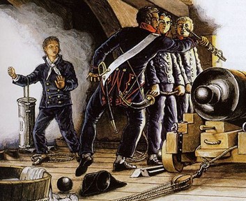
Carl, the first time I saw this picture of the boy holding one of those pouches, I realized what it was for. Now you can see them hanging above the cannons. But I don't recall seeing them out in the open on the spar deck.
- 572 replies
-
- 3
-
-
- constitution
- frigate
- (and 1 more)
-
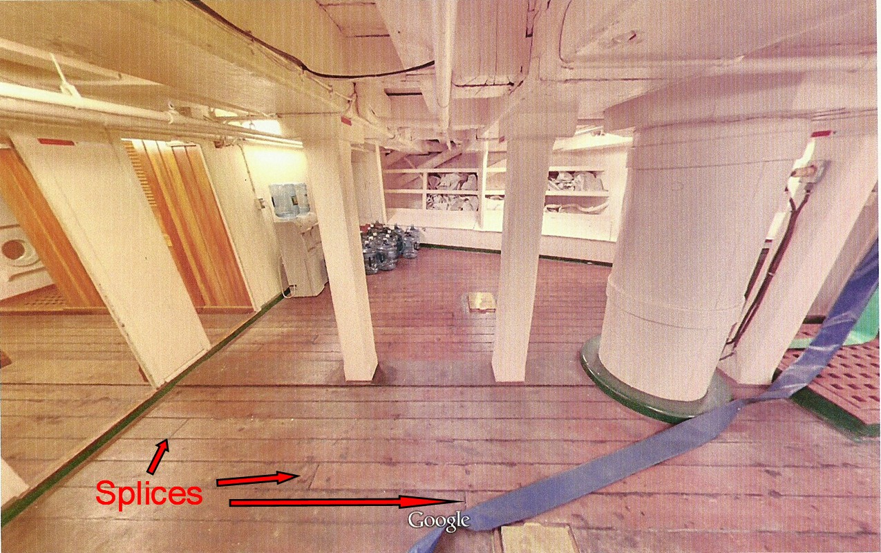
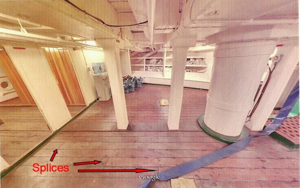
Wayne, the stanchions could be moved since they stand on the center line beam and don't go through the floor. The one I show in my sketch is directly underneath the beam. There are two more in the sail/storage room (painted white) and also underneath the berth deck beams, two in the hallway (varnished) and then they continue in the hold. No post where the stairs go up. If the center line beam is correct, it would probably be supported by other stanchions that rest on the keelson. If the center line beam is quite thick, the crawl space underneath it would be very small. Hence the use of two entrances, etc. The whole idea of this powder fill room was an add on, I believe, because earlier drawings (1819) show the fill room to be on the orlop deck. It would still be possible that the area below was originally used as the magazine but not to fill the cartridges. One more thing about the deck supports. There appears to be a number of 'carlings' or joists underneath that are spaced roughly 24 inches apart. You can see the deck splices at regular intervals and they do not correspond to the big beams overhead.
- 572 replies
-
- 4
-
-
- constitution
- frigate
- (and 1 more)
-
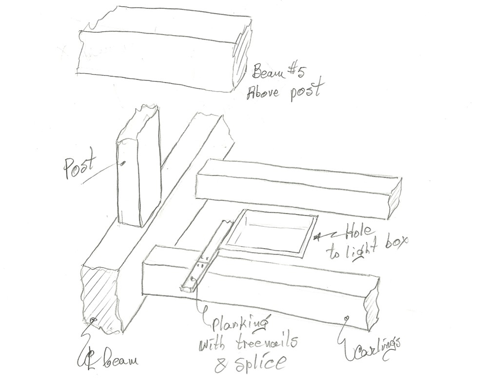
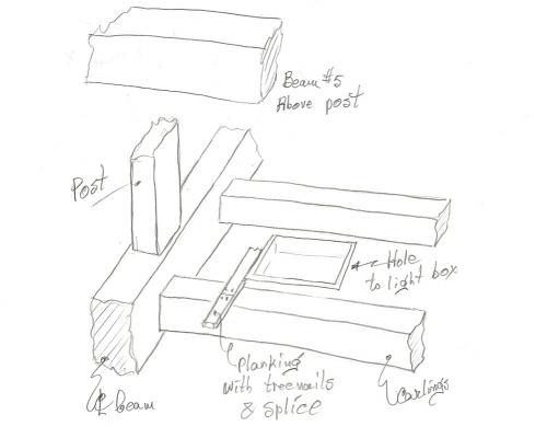
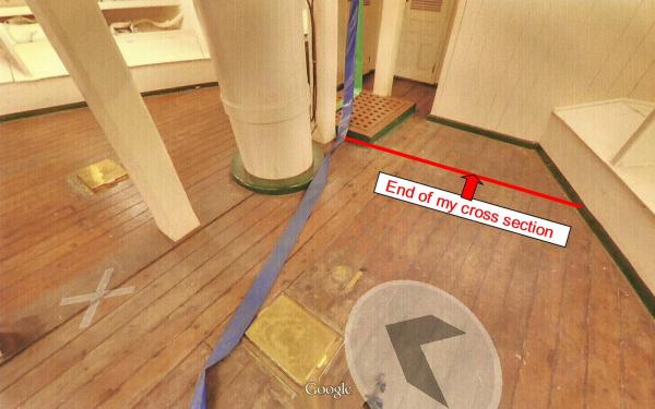
Back to the light boxes and how they are mounted. When I looked at the Google pictures again it did not make sense that those brass covers to the light boxes were right on top of the 'beam'. After all, beam #5 was above all of this on several decks, so why not here? In fact, there is a post right there to support that beam. Then on closer look, you can see that along the center-line of the ship at the orlop deck level there is another beam (I believe). Notice that the post is mounted on top of that beam (and not vs/vs). Furthermore, the Google pictures show a lot of tree-nailing in areas where there should not be any. Being that I am interested in the structural aspects of my mystery ship, here is my interpretation of what the woodworks below the orlop deck looks like. I have a few other thoughts and now I am not too sure that the powder room/magazines were two separate rooms. There is no clear indication of that yet. But if there is one, it would be underneath the center-line beam.
- 572 replies
-
- 4
-
-
- constitution
- frigate
- (and 1 more)
-
Dan that is good stuff, man. What the drawings indicate is that there are two separate magazines, one on each side.That would explain the two scuttles and two light boxes. I would dearly like to see the full size drawings because when I copied yours and blew them up, the lines become fuzzy. However, it is obvious that the crawl space down there is very limited. The rooms are completely enclosed with ceiling panels, floors and side walls. I will try to compare the sizes to get an idea of how much headroom there is and put some plans together for my usage. As before, I will take some liberties with the way I'll show the two rooms with cutouts, etc. I think Henry will be interested in this also. He has never been down there, but did indicate that there is a glass porthole on each side between the powder room and light box. Thanks to you, Dan and Henry, I am getting closer and it all makes sense. Now back to those drawings and the source. BTW I did a quick scaling from the drawings and found that the headroom in that dungeon is only about 24 inches. But at least the boys down there did not have to worry about bumping their heads against beams in the dark.
- 572 replies
-
- 4
-
-
- constitution
- frigate
- (and 1 more)
-
They came with the Model Shipways kit of the full scale model. These were just some balls left over. Check out sources for ball bearings or beads for jewelry. Here is one source http://www.precisionballs.com/catalog/index.php?cPath=35
- 572 replies
-
- 3
-
-
- constitution
- frigate
- (and 1 more)
-
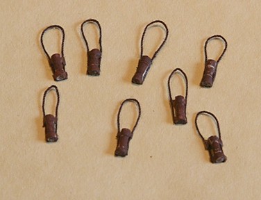
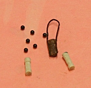
Here is a fun little side project. I am making a number of these cartridge pouches. You see them hanging from the knees above the cannons on the gun deck. They are used to carry the cloth bags filled with gun powder from the fill room to the gun and spar deck. I used some 0.08 inch dowel, grooved it and cut it to 1/4 inch length. Then I glued on some thread and painted it brown to simulate the leather. The plastic cannon balls are 0.060 inch in diameter. My plan is to have some of these hanging on the gun deck as well as on the wall next to the hatch on the orlop deck. Perhaps it would draw attention to the fill room below.
- 572 replies
-
- 4
-
-
- constitution
- frigate
- (and 1 more)
-
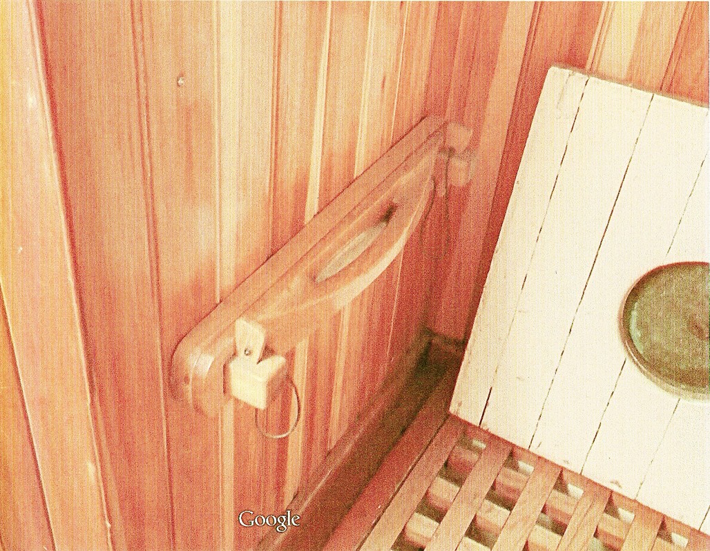
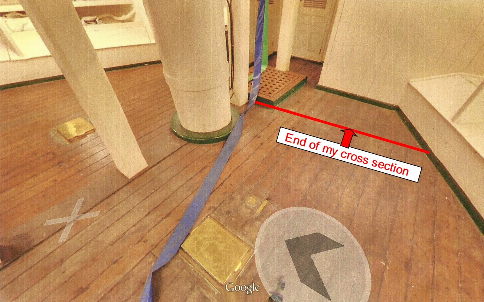
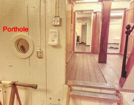
Just to come back to my favorite mystery ship. When I saw the pictures taken by Google of the various places, I was intrigued about this funny 'porthole' in the orlop deck. It is between the entrance to the magazine and the hold. No reason!!!??? Henry has told me that there are two similar ones towards the bow inside the brass boxes you can see in the floor that are used for the 'light boxes' (aka 'light rooms'). Then the following scenario occurred to me: This whole area would be totally dark unless you bring a lantern with you. But you are not allowed to open the hatch to the magazine with an open flame (big bang problem). So, before the hatch is opened to allow the boys to go down, you place the lantern on a special shelf around the corner in the hold. The light goes through the porthole and leads the way for those poor souls (hoping that someone puts lights inside the brass boxes up front). Ignore the light switched and other modern stuff shown, but I will have portholes in this wall. You know, this whole thing would make a great movie for Halloween. Can you imagine little boys going down those stairs with 'the master' carrying a lantern while he is telling them that the whole ship might blow up if they did not do this right and that they have to open the hole to hell after he goes around the corner with that light, and . . . . Where are those pictures of the gun powder kegs?
- 572 replies
-
- 6
-
-
- constitution
- frigate
- (and 1 more)