Modeler12
-
Posts
1,716 -
Joined
-
Last visited
Content Type
Profiles
Forums
Gallery
Events
Everything posted by Modeler12
-
 One more comment about the Ware drawing of the orlop deck. I studied that drawing some more and noticed several differences as well as similarities with the current layout. The drawing has numbers that are referenced to the right and it again shows that the orlop deck stops at the hold, but there is a part where the anchor cables were stored. Then the center passage way used to be narrower and the side rooms were for storage by various persons such as the boatswain and gunner's room. The sail-room was only on the starboard side. There is a scuttle going down (only one) in the same location I showed in the last picture above. But it does not mention what is below the orlop. A tiny room forward is called the 'fill room' with a light outside but it seems awfully tiny. Just as was mentioned by several of you, there have been many changes over the years. Walls were moved and rooms were changed. But I am also sure that some of the features such as the size of the orlop deck has remained the same. Again Wayne, thanks for the info.
- 572 replies
-
- 4
-

-
- constitution
- frigate
- (and 1 more)
-
Wayne, thanks for these drawings also. The first one confirms the size of the forward orlop deck as it is now (per the Google map pictures and the numbers of the beams. The last picture I show above has the hold drop right where the stairs stop. That corresponds to the drawing '1819 Ware plan Orlop'. Marquardt shows the hold to be further aft and includes more than is really there. I think I am going to modify my orlop deck to look like the drawing above and the current layout.
- 572 replies
-
- 4
-
-
- constitution
- frigate
- (and 1 more)
-
Wayne, if I understand these two drawings correctly, they confirm what I now believe is the correct layout. The lower half is the plan for the gun deck and it shows the hatches going further forward than the main one on the spar deck. It also shows a small square to the right that would be the post for the riding bits. The beams on the orlop deck are now marked with numbers starting with one near the bow. The beam just aft of the fore mast is five and as you go further aft they correspond to the eleventh beam that is part of what I am using for my cross section. Marquardt shows the little square (aft riding bit) between beams nine and ten whereas the drawing you reference has that square between beams eight and nine (more forwards).
- 572 replies
-
- 4
-
-
- constitution
- frigate
- (and 1 more)
-
Thanks Wayne. I will check this out. I appreciate your help in solving some of these mysteries. Here is one possible solution to the question I raised about a scuttle to deliver the pouches of gun powder cartridges from down in the powder room. I could not find any holes in the floors other than the two rectangular ones that Henry indicated as being the place where lamps were lowered into the 'light room'. However, the two hatches next to the stairs show a wooden cover with a round hole in the center. That hole would be big enough for the pouches to go through. So my guess is that once the grating had been removed and the boys were inside, this cover with the hole would be placed over the hatch to close everything off. In fact, there is even a sliding bolt on the inside to lock this cover in place???? Notice in the picture that the hold to the left has a false floor. The keel would be some distance lower, making the headroom available for the powder room a bit more than what may seem at first.

- 572 replies
-
- 4
-
-
- constitution
- frigate
- (and 1 more)
-
Thanks Henry. That is good information and I will have to digest all the details. Considering that there are two brass covers in the sail room for the lanterns, I am going to assume that the forward magazine goes the full width of the ship and that the bulkhead with the glazed window likewise goes all the way across. The two hatch covers just inside the small recesses next to the stairs are the only entrances to the magazine. They must have been used to lower the barrels of gun powder, the boys who did the work down there and to bring up the leather pouches with the cartridges. Unless there was another scuttle to pass up those cartridge pouches. I know that once inside there were strict rules to keep out moisture and prevent any possible sources of sparks, etc. Maybe some day I'll come and visit you and the ship and we can go down into that powder room and explore
- 572 replies
-
- 4
-
-
- constitution
- frigate
- (and 1 more)
-
Ok Mark, I understand that there were many changes, both in 1929 and before. However, I really doubt that moving those large riding bits was one of them, no matter what time frame. It would have meant a reconstruction of the forward end of all decks for no apparent reason. Look at the layout of the hatches on each deck and tell me again that those openings were not original? The grating is new, to be sure, but not the openings between beams. At least I don't think all those beams were replaced and moved What I can live with is a logical interpretation of all those factors, but when I see pictures of what is today and it does not correspond to what the drawings (Marquart's) show, I begin to doubt. Locations and size of the hatches is one, and there are many more in my opinion. I don't want to belittle the author's input, but in this case I stand firm: He was wrong in this part.
- 572 replies
-
- 3
-
-
- constitution
- frigate
- (and 1 more)
-
To be honest with you, George, I still think the book has real value as long as you don't do as I am trying to do. The drawings are mostly very good. The details of the rigging helped me tremendously. It is just too bad that he made some errors in the four decks (and yes I am including the spar deck because he is at least consistent and had the stove pipe in the wrong position there also. Besides he left off the hatch just forward of the fore mast). What the Google images show is that the forward section of the orlop deck is mostly the sail room with two cabins just aft. The doors look new and there are padlocks on both. Curious what is inside. There is also the carpenter's walk between the cabin walls and hull planking, just like Marquardt shows. Just to update: I have removed the planking on the gun and berth deck to make room for the extended grating. I will have to make new frames for those hatches. That also meant that the carlings and joists between the second and third beams had to be cut away and replaced. Now it is back to the drawing board to design those hatches with stairs and gratings as Google shows. However, the passage way is right midship and there is no indication on the beams and deck planking to indicate that walls and openings were removed (eg the light room etc,) I am leaving the orlop deck along until I can get some answers about what that area used to look like. Right now I think there were too many changes made down there.
- 572 replies
-
- 3
-
-
- constitution
- frigate
- (and 1 more)
-
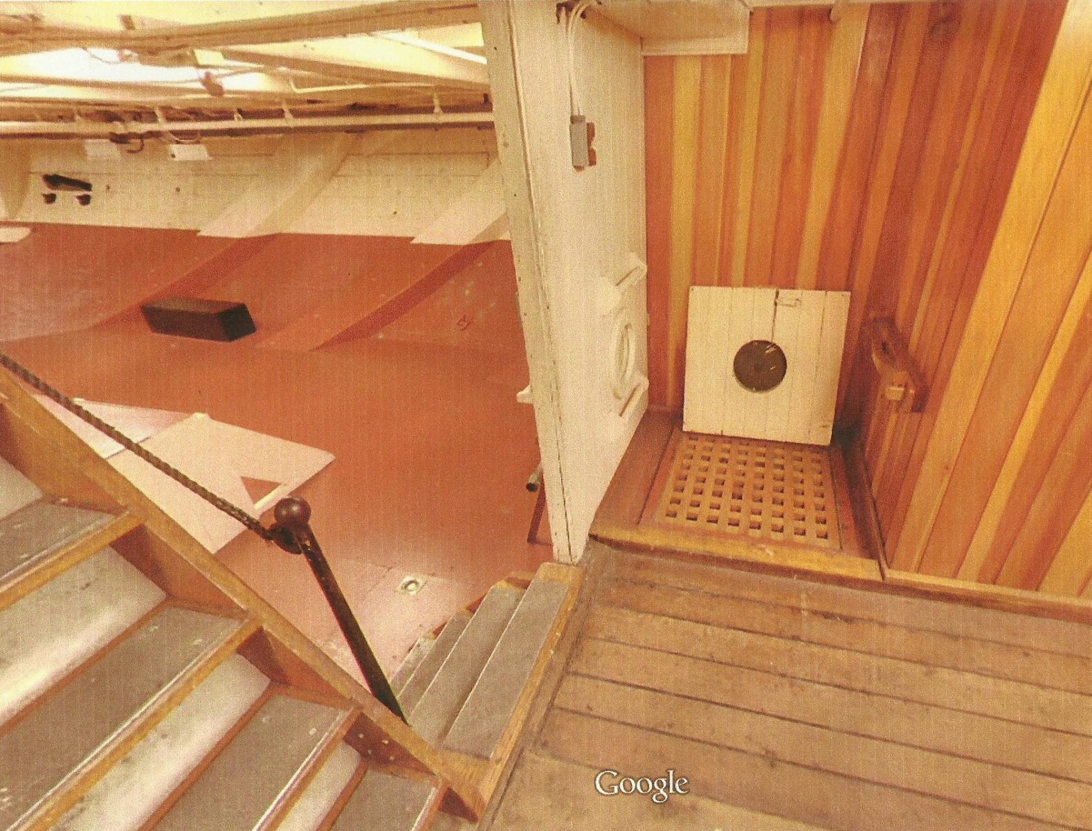
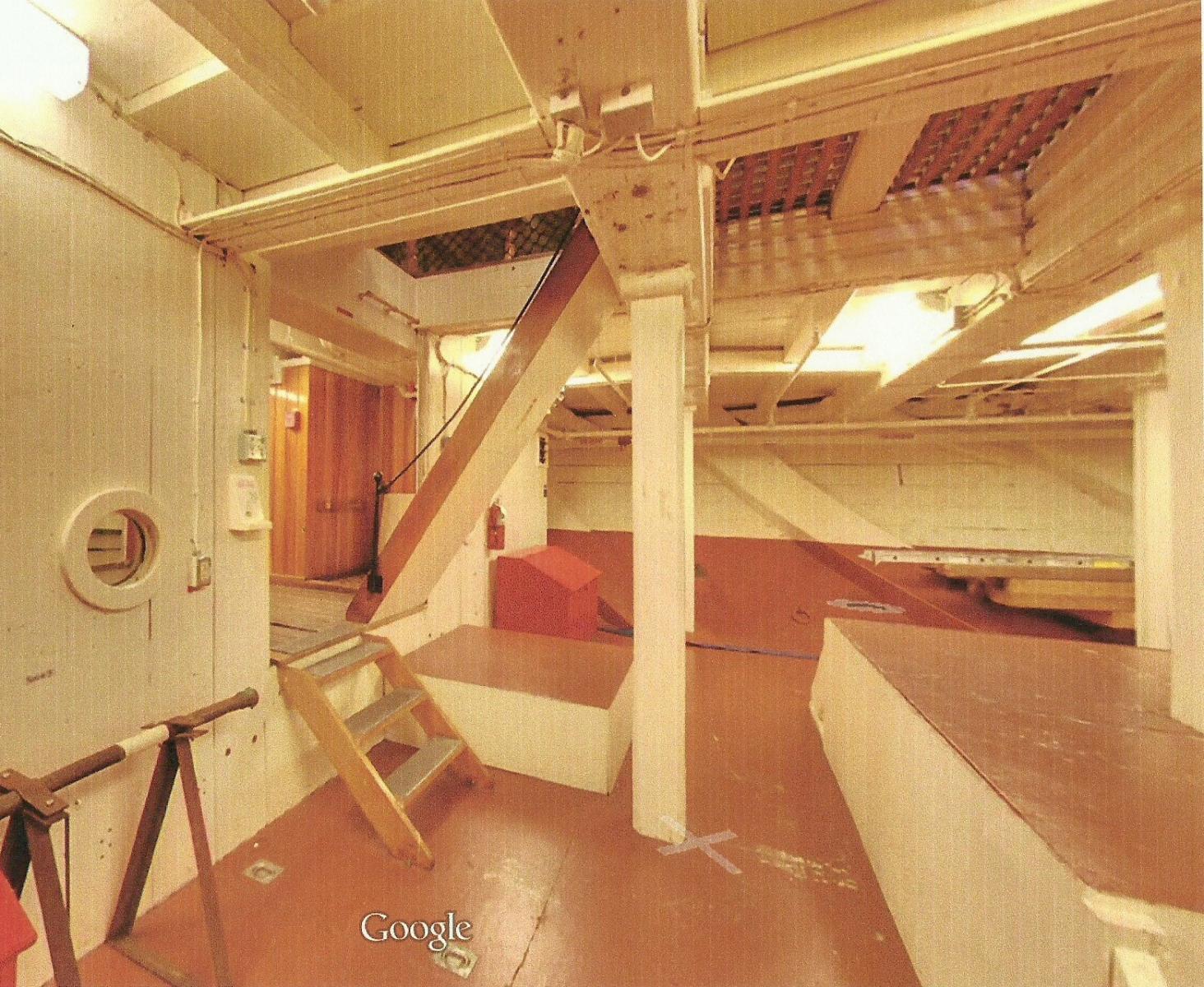
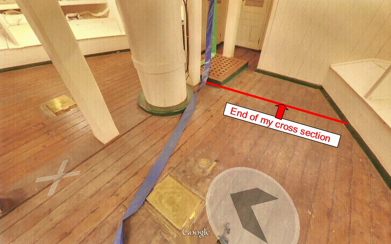
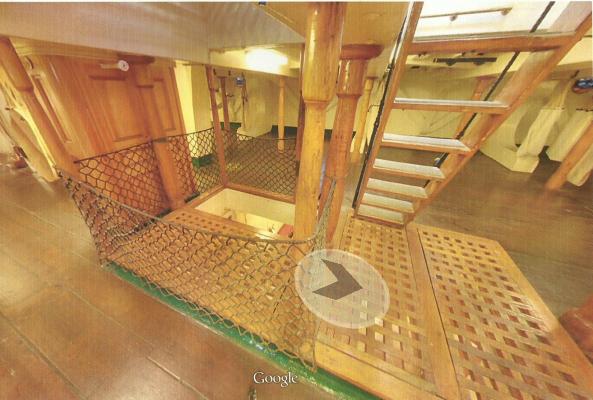
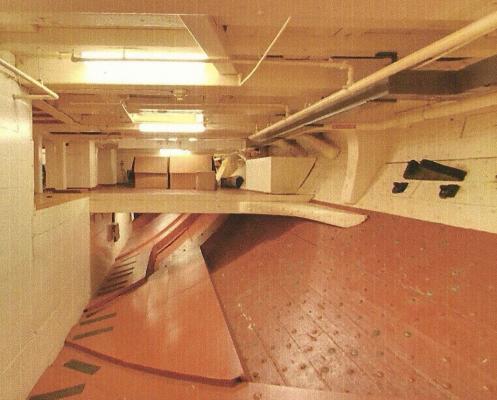
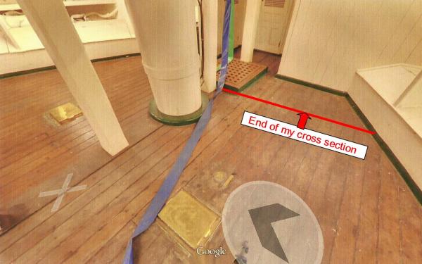
My problems are growing. All along I have gone by the drawings provided by Marquardt and now the location of the riding bits on the gun deck are also causing problems on the berth and orlop decks. Just like the gun deck where the hatch cover extends further forward, so do the hatches on the other decks. I had noticed that Marquardt had added an extra beam but now it also seems that his drawings of the orlop deck are in question. And I don't believe it is simply a matter of past remodeling. Looking at the images of the Google clips, the forward section of that deck is very short before it drops down to where perhaps the anchor cables were stored. Looking up at that point you can see the extended grating of the berth deck. Notice also the little porthole in the wall. There is a similar one on the other side. Barely visible is the inside where there are gratings that again lead down presumably into the powder room. What is not shown in any of the Google pictures is the entrance to the light room. It certainly is not where Marquardt shows it. Could one of those two grating be for the light room? Help, Henry!!! The next picture is taken on the berth deck and shows the same grating and the opening for the stairs going down. The ship's bow is to the left. The little cubicle is probably the cabin for one of the officers. My cross section starts at the right edge of the grating.
- 572 replies
-
- 5
-
-
- constitution
- frigate
- (and 1 more)
-
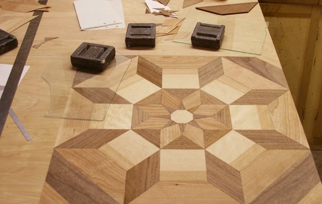
Indeed, Dave, Henry has been very helpful to me in the past. He went back to the ship and took special pictures of the rigging for me last year. However, he is extremely busy right now with his commitment to cut wood samples from the refurbishing that is going on. I will send him an email but would expect slow or no answers until he has more time.
- 572 replies
-
- 2
-
-
- constitution
- frigate
- (and 1 more)
-
One more thing about the orlop deck. Below it shows that there might have been (or is) a split level. Notice the old knee holding that part up. Could that be part of the mid 'powder room'? The one forward surely has a lot less head room below the orlop. The more I look at these pictures, the more I get confused.
- 572 replies
-
- 3
-
-
- constitution
- frigate
- (and 1 more)
-
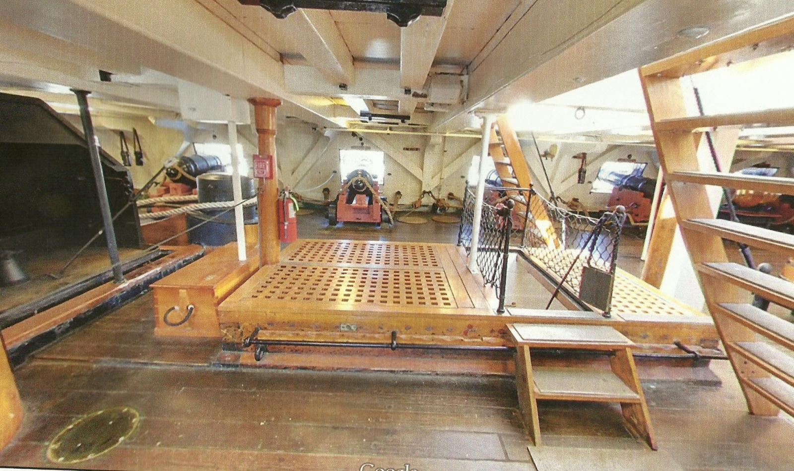
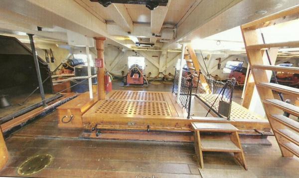
Tom, I want to thank you again for steering me in the right direction. Google has a couple more interesting 'walk throughs'. The orlop deck, picture wise, was a complete mystery to me before (and, of course, the same with the powder room). Here it is: https://www.google.com/maps/@42.372495,-71.056602,3a,90y,286.73h,83.24t/data=!3m7!1e1!3m5!1sOxclVsko0oMAAAQZN_whPw!2e0!3e2!7i13312!8i6656 This area is not open to the public and apparently has been modified to house the fire sprinkling system, for example. There are a number of 'original' knees that also seem to indicate that part of this deck was 'split level'. HMMM! The picture below appears to be the 'sail room'. It has shelves and cabinets on both sides of the ship. I would think that jib and fore sails would be hoisted through the hatch you see forward. But others would go aft along a hallway shown in Marquardt's drawings. I am not including the forward hatch. But since it shows going down, I believe it was the way for the boys to deliver powder sacks to the gun deck (from way down in hell). When I get to it, I am still going with my fabricated plan for the powder room. it would have been underneath the orlop deck towards the front where, next to the fore mast, you can see two brass covers. Does any one know what all of that was about? Credit goes to Google for the image below.
- 572 replies
-
- 3
-
-
- constitution
- frigate
- (and 1 more)
-
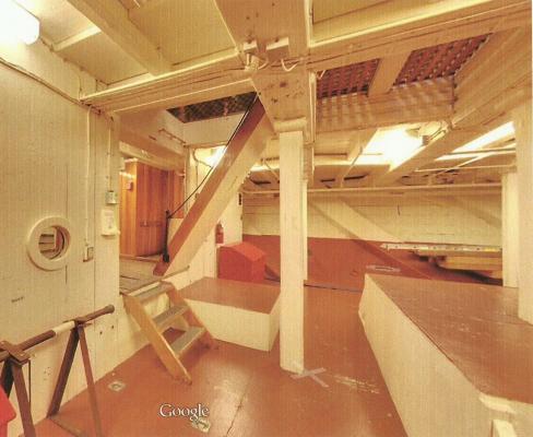
Here is what Tom referred to. You can see that the gun deck hatch extends to the left further than the main hatch above on the spar deck. The stairs to the right go up to that deck and now you can see the narrow stairs going down to the berth deck. Great to know!!!
- 572 replies
-
- 3
-
-
- constitution
- frigate
- (and 1 more)
-
Thanks fellows. Indeed those bird's eye views confirm that the Model Shipways drawings are correct. But then the stove pipe does not line up with what is below. I have a number of photographs of the stove and looking at the beams overhead and the spaces between hatch covers it is still not totally clear where the stove is in reality. It is still possible that the aft riding bit is too far back (one set of beams), but that also means that the hatch on the gun deck (that is right behind the aft riding bit) is also too far back. I am a bit too far into this thing to stop now and redo the gun deck and stove location (I think). But I will reconsider this some more. Tom, your suggestion solved my problem. Google indeed shows that the riding bit and hatch on the gun deck should be one set of beams more forward. That means I have to take of some of the deck planking and relocate the riding bit and oven platform. But that is doable. What it also shows is that there is another stairway down to the berth deck and that is good, because (besides the one coming down from the spar deck) it is the only one shown in this cross section. This change could have been made back many years ago, but it would seem strange that the change involving those heavy riding bits and stove was made in the first place. Could it be that Marquardt is wrong again?
- 572 replies
-
- 5
-
-
- constitution
- frigate
- (and 1 more)
-
Another problem with the plans. I believe there is a mistake in the plans for the full model (Model Shipways drawing 4 and others). The location of the stove pipe and hatch is shown too far forward. The drawings shown by Marquardt make a lot more sense for the following reason. There are two sets of heavy riding bits on the gun deck and the stove fits between the fore and aft bits. The fore bit has to have room between the stove and fore mast. Model Shipways drawings don’t allow for that. In fact, photographs also show that the stove is located as shown by Mr. Marquardt. It would be interesting if someone would measure the distance between the main hatch and the stove-pipe hatch and see how that translate to both sets of drawings. I am not going to change my full scale model since that would involve redoing the deck planking. But I am glad that the work I have put in the cross section is correct as far as the location of the stove. Of course, the stove pipe and hatch on the spar deck will be located accordingly.
- 572 replies
-
- 3
-
-
- constitution
- frigate
- (and 1 more)
-
Nice work, Tom. I did not know that the pin rails had so many changes. Can you pin-point the location? It is also refreshing to see that you have a 'scrap bin', some thing we all have at one time or other, but rather ignore.
- 1,350 replies
-
- 5
-
-
- constitution
- model shipways
- (and 1 more)
-
Micro Drills, Revisited.
Modeler12 replied to Modeler12's topic in Modeling tools and Workshop Equipment
That's right, Ken. The reason I had to order more is for that same reason. Drilling those tiny holes by hand (pin-vise) is not too secure. I have had much better results by using my dremmel-like tool mounted on the mill or drill press. But some times you don't have a choice. What I also like about these drills is that the shaft has a larger and constant diameter which makes it easier to interchange bits without having tho switch collets. Side pressure on those tiny drills or milling cutters is indeed an issue and even with a 1/16 inch milling cutter on wood, I have to be very careful. I have not tried any smaller. But if tungsten-carbide bits break easily, I don't see the advantage of using end mill bits (with the same kind of twist) versus twist drills. They are about twice as expensive (Proxxon). -
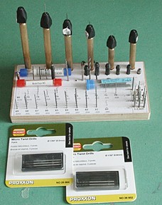
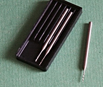
I just received more micro drills from the US distributor of Proxxon. They have a thick shaft and are made of solid tungsten carbide. The ones I ordered were 0.5 and 0.8 mm in diameter, others (bigger) are also available. The second picture is of the three at 0.5 mm. I have a supply of 'micro drills' that are simply straight pieces of metal with a slight spiral at one end. They are the typical Chinese made products available at most places. Those cheap ones break easy; they burn their way through the wood (don't try to drill metal) and leave a hole of unknown diameter. I use them for places that are not critical (holes for eye-bolts, etc). But if you want to be a bit more careful, use the Proxxon drills - they are also made in China, but apparently under better controlled conditions-. Here is the web site http://shop.prox-tech.com/k/search?q=micro+drill The big question is 'Will Proxxon be willing to make other drills that cover the smaller ranges' so often used by us? PS. This is not intended as a plug for Proxxon, just my thoughts about quality and what I need.
-
Filler block question.
Modeler12 replied to Ronjja76's topic in Building, Framing, Planking and plating a ships hull and deck
It looks like your filler blocks do not have a lot of compound curvature. That makes it easier than when the filler block is up against the bow or stern where the curvatures go every which way. What I ended up doing is to rough cut the block by saw and then sanded the rest with a disk sander to a bit larger than needed. To prevent my knuckles and DNA from being part of the model, I glued the block to a handle using hot-melt glue. It gave me lots of room to maneuver the block while sanding and made it easy to dry fit numerous times.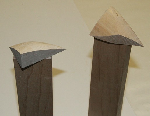
-
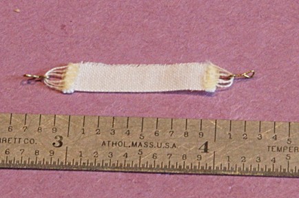
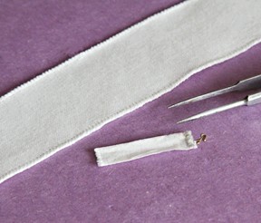
Actually George, this was not needle-work but glue that I used. My fingers are just not good enough to do the stitching, so I resorted to using Titebond. The picture below shows the back side with the glue just on the machine stitched ends. Having done that, I now know that the hammock is too long (good for a guy 6'4", but not your typical sailor). So, the next series I'll try will be with an edged strip of fabric that is narrower. Again, however, the overall length has to fit the beams
- 572 replies
-
- 6
-
-
- constitution
- frigate
- (and 1 more)
-
When I was making sails, someone asked what fabric I was using. All I remember is that I went to Joanne's shop and picked out the lightest and most uniform white cloth I could find. No ID that I remember. But the close-up below shows that it is a square weave with a thread count of 84 x 84 per inch. Maybe that might help others. After doing the other end and cutting the hammock to a quarter inch width, I still need to 'stabilize' the edges.
- 572 replies
-
- 4
-
-
- constitution
- frigate
- (and 1 more)
-
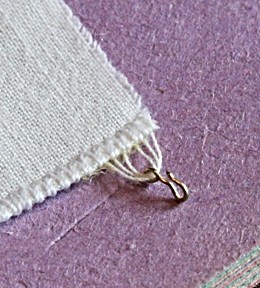
Thanks Mark. I will consider that approach. Meanwhile I am still experimenting with alternate methods. I still think using the very light weight fabric I have is a bit easier than wet tissue paper. However, I am using white glue on the edges to stabilize the hammock shape. Also, I am committed to using the 'hook and eye bolt' approach (instead of the other way around). Hence the hammock will have a ring with hook. For my purposes that is not all that critical. More to come. Here is my second approach to making the hammocks. I had trouble with sewing the lines that go through the eye of the hook. They did not line up right. This time I laid out three lines (doubled up) and glued the hammock material to it (on the back side). It is tricky but if I can repeat what I show below, I will be satisfied.
- 572 replies
-
- 4
-
-
- constitution
- frigate
- (and 1 more)
-
Good idea, George. That would work, I am sure. The biggest problem I have (not really that big), is to hand stitch the ends of the fabric and have it come together with the eye in the hook at about the right space. In other words, the length of the webbing to the hook and how that relates to the overall length is tricky to control. I don't think I will be able to make enough of them so they look like they are the same height when hanging next to each other. The shape comes afterwards (actually, a body in the hammock would be best).
- 572 replies
-
- 4
-
-
- constitution
- frigate
- (and 1 more)
-
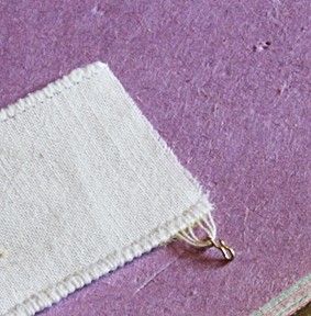
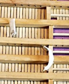
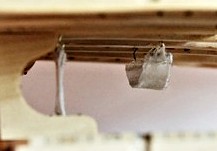
Making hammocks is not easy! I took some thin fabric (the stuff I used for making sails) and stitched the edges of a one inch wide strip. It is called 'overcasting' by a seamstress. Then I sewed a thread back and forth through one end and the eye of the hook (not shown, sorry). It took several tries until I got the hang of it. The tricky part is to get the spacing right as well. The picture below, to the right, is looking up where one was hooked to the eye bolts. The folded hammock to the left was a 'mistake', but they also serve a purpose, right??? However!!!!! Is all of this worth the effort? When I hung one of the hammocks on the hooks below the gun deck and added the berth deck to see what it would do. . . . Those hammocks are lost. Notice I even added a hammock folded double and re-hooked. I am going to make some more and attached them aft (fore-ward in the picture) hoping they would show up better. AS you can see above, material is no problem.
- 572 replies
-
- 6
-
-
- constitution
- frigate
- (and 1 more)
-
Replacement blades (2 per package) cost $4.50 to $5 depending on size at Joanne's sewing store. I have sharpened the old one with limited success. Any nick on the edge causes hick-ups on the cut.
-
I use them on fabric (sails, hammocks, etc). The advantage is that you cut the material while it is lying flat on the cutting board and you can see where the blade is going. I have also used it to cut veneer. It is just like quilting.