HOLIDAY DONATION DRIVE - SUPPORT MSW - DO YOUR PART TO KEEP THIS GREAT FORUM GOING! (Only 13 donations so far - C'mon guys!)
×


Modeler12
-
Posts
1,716 -
Joined
-
Last visited
Content Type
Profiles
Forums
Gallery
Events
Everything posted by Modeler12
-
 Here you go again, Mark. Do you mean to iron on those rivets like this?
- 572 replies
-
- 5
-

-
- constitution
- frigate
- (and 1 more)
-
You know that is what I also thought. I had done that for the full scale model by pre-drilling the bulwark planks before installing them and adding the rivets at that point. Mr. Hunt did it the hard way by hand drilling the planks after they were installed. If you are interested in the rivets shown below they are available in different sizes from Titsy Train Group. However, when I tried to do that on the C-knees it was hard or almost impossible to reach the spots in the curved areas. Then I thought that if I were able to do it, I would have to do the other knees the same way and I quickly gave up on the idea. What I may try is to add a drop of thick, brown paint. But then again, I prefer to keep this project 'clean' and not use paint except black, may be.
- 572 replies
-
- 5
-
-
- constitution
- frigate
- (and 1 more)
-
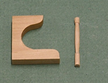
Nothing to 'borrow', Grant. This whole forum is full of ideas and I think we can use any of the information for our own use. I did run into a situation when making flags and asked (and got) permission to copy flag designs from the editor of the web site (not this one). What I had problems with when trying to use the metal spring clamps is that the edge was too narrow and I could not adjust the clamping distance. Hence, I made my own (a few hours work). Moving right along with the berth deck (as if nothing happened ). I made one of the 16 posts I need for the berth deck. They stand in front of each C-knee. But rather than free standing, I decided to keep them a tad longer and drill holes in the deck where they should go. Then later during assembly I can simply glue them in place using the knees for height alignment.
- 572 replies
-
- 6
-
-
- constitution
- frigate
- (and 1 more)
-
Major hick-up. I just realized that the orlop deck and berth deck don't line up vertically. They are off by about an 1/8 inch. When I checked the drawings I found that I had made a change in the beam thickness for the orlop deck without changing the spacing between them. Hence the orlop is too short. The change was for five beams from 0.21 to 0.18 inch (5 x .03 = 0.15 inches). The picture below (with both decks stacked on top of each other) doesn't show it that way too clearly, but I will make sure that the gun and spar deck beams are spaced correctly. I think I can live with this mistake as long as I keep the front edge lined up.
- 572 replies
-
- 6
-
-
- constitution
- frigate
- (and 1 more)
-
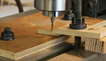
Mark, go at it. At first I thought to add a strip of sandpaper to the underside of the clamp to give it some more bite. But I found that was not necessary. The nut and leverage was more than enough to give a solid hold to the work piece. Of course, I am working with tiny pieces. And again, as you well know with the mill and clamps, you want to have the clamp piece supported a bit higher at the tail end and the stud close to the work piece. One more comment. I have a piece of plywood on the bed with two bolts holding it down. This has come handy for several operations such as drilling the hatch cover holes and notching the carlings. It also gives me a bit more assurance that I don't run into the bed by accident. I tried to align the front edge pretty close along the x-axis for reference.
- 572 replies
-
- 3
-
-
- constitution
- frigate
- (and 1 more)
-
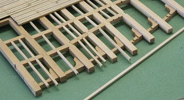
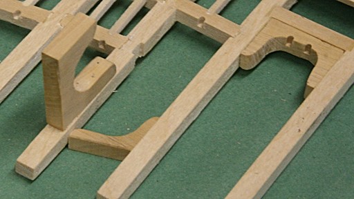
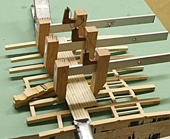
Here are the seven knees temporarily fitted between the beams. Towards the bow the ledges have not yet been cut and fitted. Easy. The way I cut the grooves for the ledges is on my milling machine. Rather than using the heavy cast iron clamps, I made mine from some scrap wood. The end cutter is 1/16 inch diameter, the width of the ledge material. I also decided to not put the lodging knees along the port side. They would be hard to see with the deck planking on top. Instead I will use them for the orlop deck (along the starboard side).
- 572 replies
-
- 7
-
-
- constitution
- frigate
- (and 1 more)
-
OK, Antony, you asked for it and here is the next step. Each of the lodging knees has to be filed to fit between the beams. Then it has to have a groove for the ledges, deep enough so the top surface of the ledge is flush with the top of the beam. Since the beam thickness changes as I go fore, the depth of the groove also changes. Hence, I have to do each one separate. All of this is a loose fit because the exact location is yet to be determined. The same process will be used later for the lodging knees in the orlop and gun decks.

- 572 replies
-
- 8
-
-
- constitution
- frigate
- (and 1 more)
-
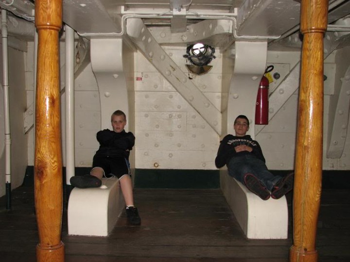
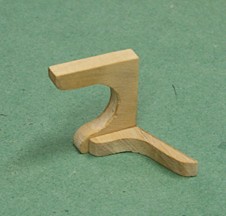
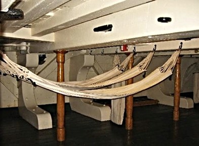
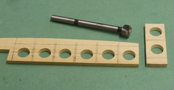
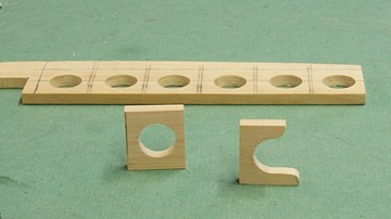
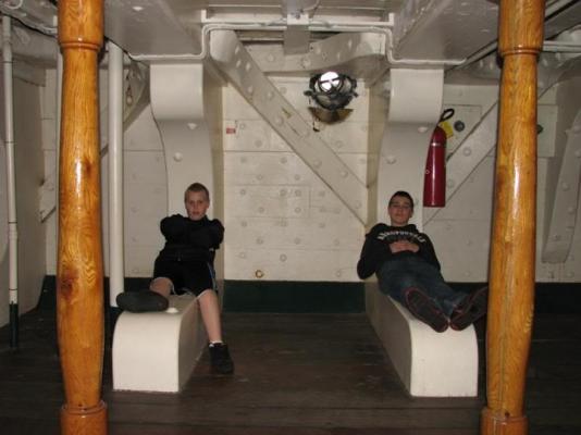
The lodging knees are a bit more complicated. Because of the beam spacing, the horizontal sizes vary. Plus because of the hull shape, one leg of the knee tilts as an angle which also varies depending on location. I laid out the design of each on a piece of boxwood (0.015 inch thick) and drilled 1/2 diameter holes like I did on the standard knees. Notice how the location of the holes, the angles of the lower edges and the horizontal spacing all vary. For the angles I used the drawing on page 72/73 of Marquardt's book. Then it was a matter of cutting the knees and sanding them to contour. Below are the two knees butted together. They are up-side-down and the back side of the standard knee still needs to be shaped to the hull contour and clearances for the waterways, for example. Like in the picture above with the two boys sitting on the knee, the short legs are pretty close of the same size for both pieces. This particular knee goes between the two beams just aft of the fore-mast. Oops! The lodging knees I just made really belong inside the berth deck structure. What the photograph with the boys shows are the lodging knees of the gun deck. The parts I made are fine but they need to be located in the right level. Hence my second photo above of the up-side-down view is wrong. Here is what it should look like:
- 572 replies
-
- 10
-
-
- constitution
- frigate
- (and 1 more)
-
Thanks George. I just realized that I need to make a few more because the eight I have will be on the port side. To show the construction on the starboard side I should use at least three more. Too many and it becomes too crowded and hard to see things inside. The same applies to the other knees.
- 572 replies
-
- 3
-
-
- constitution
- frigate
- (and 1 more)
-
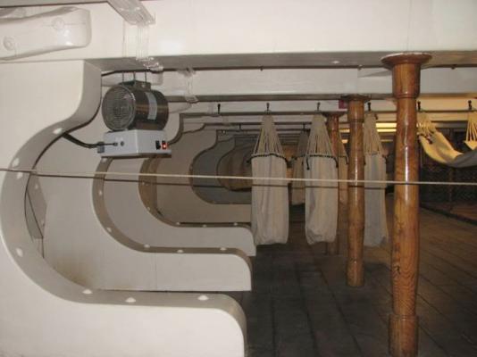
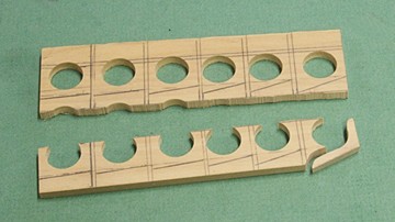
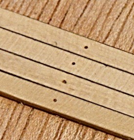
There are three types of 'knees' on the berth deck. They are all heavy and bulky to take the brunt of the heavy cannons on the deck above. The most obvious knee is the C-shaped part that fits between the top beam and deck. The other two are called 'hanging' and 'lodging' knees (the latter is near the top in the second picture). I made eight of the the C-shaped knees, as shown below. A 1/2 inch Forstner drill bit gives a nice, clean hole and then it was a matter of band-sawing and filing to get the contour. The height is 0.9 inches (70" full scale) and the length 0.8 inches. The thickness is slightly less than that of the beams (0.015 inches). The height of these parts will determine where the gun-deck beams will be located. The left sides will be fitted to the contour of the inboard hull shape.
- 572 replies
-
- 11
-
-
- constitution
- frigate
- (and 1 more)
-
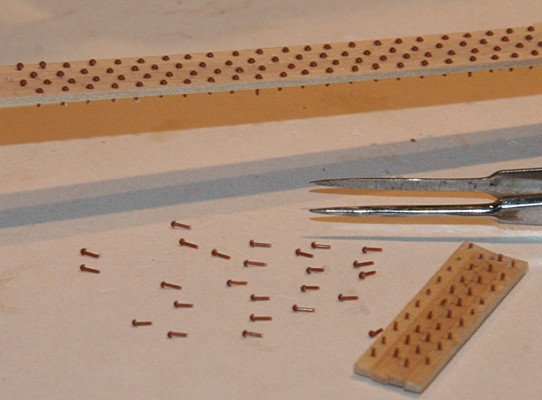
I have also used scrapers for many years making furniture. However, for the deck planking of my current project I cannot use them because I use brass tree-nails. I have not tried it, but I am afraid I would tear out the brass or damage the planking with scrapers. Why brass wire for tree-nails? I found them to be more uniform and easier to install. I pre-drill the holes with a #78 drill and insert the .015 inch wire with a touch of CA. After sanding the surface, I apply a tiny dab of the patina I use to blacken the ends, which at full strength, reacts immediately. I wipe the surface with a wet towel and dry it as quickly as I can and apply a coat of poly-wipe. There is no effect on the wood that I can see even after several weeks sitting around.
-
If you are interested in flikering LEDs, there really is no need to build complicated circuits. For less than four dollars each you can buy the LEDs with built-in circuitry to give you random flikering (not flashing, mind you). I have bought LEDs from this same company and they arrived quickly and were easy to use. I had them include the transformer (3 volts) which comes with a switch and connectors. I have used them in the past (two windmill models) and they have been lit for more than two years continuously. It makes a nice night-light as well. http://www.modeltrainsoftware.com/flickering-led.html I am planning on using two (red and orange) to simulate the fire in the stove for my cross section work. Check out the video in the web site above. sorry Figuerres, I noticed your post above just now.
-
Hi Antony, The place where I bought the LEDs also makes a flickering type for less than $4.00. I think I'll get a couple to try for the fire-place I have in mind. http://www.modeltrainsoftware.com/flickering-led.html
- 572 replies
-
- 3
-
-
- constitution
- frigate
- (and 1 more)
-
Here are a few more planks with the wedge clamps in place; along with two metal spring clamps at the ends and a clothes-pin near the center. Things do get crowded and this is only a dry fit. The problem is that all those plank joints need extra work compared with using six inch long pieces. Each joint needs to be adjusted for spacing and also more clamping (they don't want to follow a straight line). The picture does not show this clearly and maybe I can show that in more detail later on. Mind you, this needs to be glued down, sanded, blackened, etc. Any way, it is an interesting exercise.
- 572 replies
-
- 7
-
-
- constitution
- frigate
- (and 1 more)
-
JS I do have a small milling machine and that helped I had toyed with the idea of using wooden dowel for the shafts, but that would cause the whole thing to rotate and wobble. I suppose you could drill a series of holes and file the slots to fit a rectangular bar. I just made the clamps today, tried them briefly, but the proof of the pudding will be in actual use. I am sure that a screw, rather than the wedge, would be better and give you more control. But this was a couple hours project. One more comment about the 'wedge'. I used some blood-wood that was 1/8 inch thick and had to taper each one to fit the sliding jaws. Hence, I tied a thread to the wedge and jaw so they would stay together. I may give some thought about modifying this . . . . . .
- 572 replies
-
- 3
-
-
- constitution
- frigate
- (and 1 more)
-
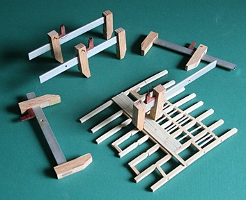
Now that the full size model is finished, it is time to get back to the cross section. When I planked the orlop deck I had some trouble applying pressure to the sides of the planks and get a nice tight fit. For the berth deck I decided to make some wedge clamps. I took a piece of 1/8 x 1/5 aluminum bar and cut it into six inch sections. The jaws are made of oak, slotted to accept the aluminum bars. The short jaw is epoxied, the sliding jaw has a longer slot to take the tapered wedge as shown below. I found that having the wedge on the inside as shown gives me better control of pressure and adjustments. But I can go either way. I also added some sandpaper to the jaws for extra bite. Now I can proceed with the planking of this deck.
- 572 replies
-
- 8
-
-
- constitution
- frigate
- (and 1 more)
-
Got it Mark, and I like that idea. Too bad we are a few miles apart, or I would join you in a 'what-ever-kind-of-drink-we-like'. Some day my admiral and I will be coming up north and stop at Medford. It might be on the way to another cruise via Un-Cruise, a great company with lots of activities to keep the mind and soul alive. It could be an interesting trip up the Columbia River.
- 732 replies
-
- 2
-
-
- constitution
- model shipways
- (and 1 more)
-
Thank you all for your nice comments. If it had not been for this forum and all the great members and their contributions, I would not have come to this point with this model. There were several times that 'priorities' took the best of my time. But then I came back and worked on something that can be relaxing, mind boggling at times, and kept my interest and skills at a high level. I gave up golf several years ago because my frustration level gets high. With this hobby I can sit back right now and say, 'Calm down, enjoy, have another look (or beer).' And it works. Now it is on to the cross section for more details, more problems to solve and more mind boggling things to solve.
- 732 replies
-
- 3
-
-
- constitution
- model shipways
- (and 1 more)
-
Sorry, Mark. I am missing something? I will agree that there were issues with the main-braces (too close to the hull and touching the boats), but 'splices'?????
- 732 replies
-
- 1
-
-
- constitution
- model shipways
- (and 1 more)
-
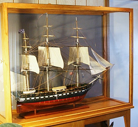
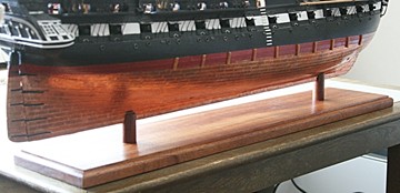
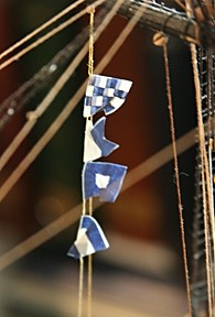
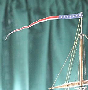
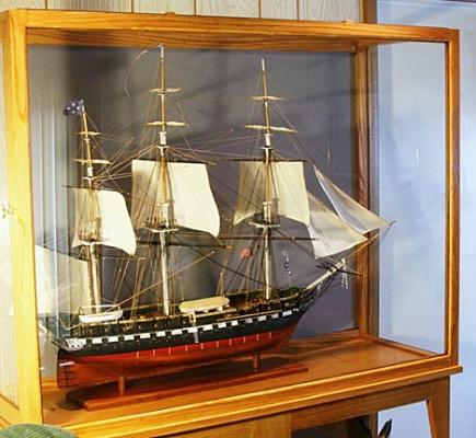
She is finally finished. It only took four years with major interruptions, to be sure. After some minor repair work, adding the boats and making the mahogany base, I hoisted the flags and let her sails fill with our family room air. One final touch will be a small brass plaque with the name and date mounted on a piece of the wood hopefully coming from our USS Constitution sailor friend. It will go inside the case in front of the bow.


- 732 replies
-
- 9
-
-
- constitution
- model shipways
- (and 1 more)
-
My guess would be the plank(s) that go across two beams that are located between two immovable objects such as a mast and hatch. Planks could be shorter if they were located right on top of a carling, but I would really frown on that.
-
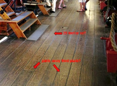
Again both Mark and Ulises, I did not mean to belittle the work you put into your post about the spacing. It is important and very interesting, to be sure. What I was referring to is that what Ulises did does not always apply to the real thing. Indeed planks vary and so does the spacing of the beams and joints. Below is a picture of the Constitution as she was a few months ago. It is the gun deck with oak planking. I am sure that these were not the original planks (well not really sure), but the spacing and size is not 'the best'. Notice the joint spacing of every third plank and the length of this particular one was only 25 feet. Ulises's premise is based on several assumptions that may need some 'research' rather than 'what ever you like'???? Perhaps not all ships were planked that way and perhaps this is a mute point.
-
Mark with all due respect to Ulises Victoria, he assumes that all his planks are 120 mm long and goes from there. In my scale that is 30 feet, fine. However, the spacing of my beams is not uniform in the forward section (because of the fore-mast and other reasons), so I have to adjust the joints accordingly. In addition, I will have 6 spaces, and that adds to the 'count' (135246). Perhaps I will stick to the 'simple' version. Is it that important?
-
In other words, something like this. A bit harder to keep track of, but that's ok. or this
-
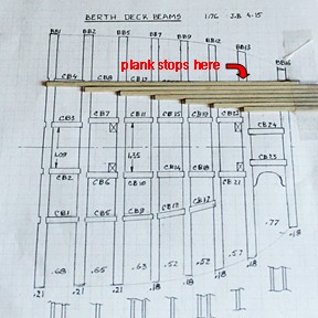
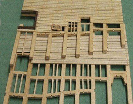
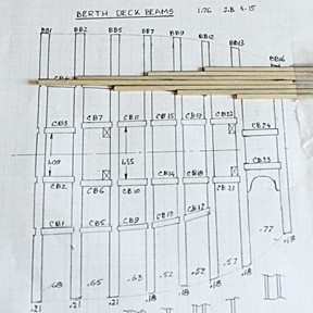
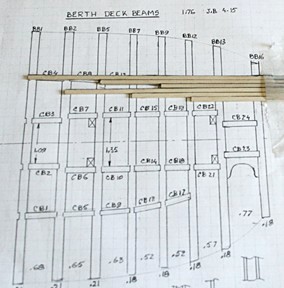
I like to extend that a bit, JB. The butt joints are not only on top of the beams, but should be staggered so that the joints don't line up too much. For my forward cross section of the USS Constitution I am using planks that are around 25 feet long. Some will be a lot shorter, of course, in order to fit the six inch long model. But my point is that there will be several joints and I want to make sure that those visible from above will have the proper spacing. Here is a mock-up on top of one of the beam spacing drawings. The planks are loose and not yet finished nor cut to the right length.