


Modeler12
-
Posts
1,716 -
Joined
-
Last visited
Content Type
Profiles
Forums
Gallery
Events
Everything posted by Modeler12
-
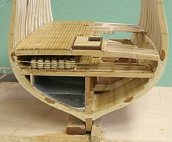
 I am finally getting to where I can install and glue the berth deck in place. The cabinets and shelves in the storage area are glued down (and I even cut and fitted the clamps for the gun and spar decks). The stairs from the berth deck down to the orlop (and the short one back up to the hold deck) are fitted and ready to be glued in place. All of this will be more visible when some of the frames are cut away.
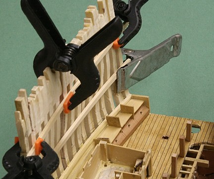
- 572 replies
-
- 9
-

-
- constitution
- frigate
- (and 1 more)
-
BTW you are probably aware that the ship was restored extensively before she left San Francisco and went back to Oslo. http://www.corbisimages.com/stock-photo/rights-managed/U1738112/large-vessel-transporting-smaller-gjoa-near-san I wonder who the contractor was that did this work in the US and if that company has details for you (or is that one of the 'friends' you referred to?)_
-
That explains a lot of what you have found. I am surprised about all the details you did find and I wish you good luck. I will keep an eye on your progress. Interesting!!! I wonder why 'Amundsen and his friends' are blocking the details. What would they have to loose by you making a model of their famous ship???
-
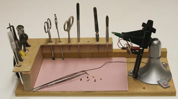
The idea of the tilting table is pretty simple, and making one yourself would not be that difficult. If you want some more pictures of the one I have, let me know or go to the Sherline web site to see more details. Go for it George.
- 572 replies
-
- 2
-
-
- constitution
- frigate
- (and 1 more)
-
George, the only one that I know of is from Sherline. The problem is that they don't use the metric thread system and you would have to drill a couple holes to adapt to other mills that use the metric dimensions. Is that tilting table really too large for the Proxxon mill?
- 572 replies
-
- 3
-
-
- constitution
- frigate
- (and 1 more)
-
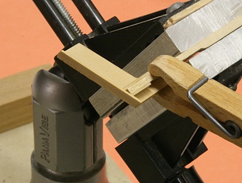
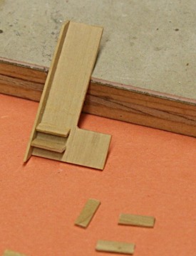
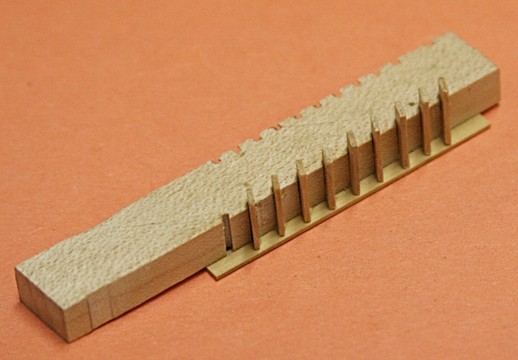
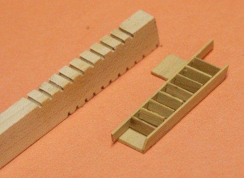
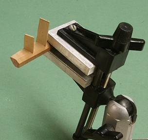
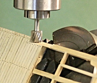
Making the stairs is tricky also. My first attempt was to install each tread one by one using a 'gauge' with the 30 degree angle I wanted. I quickly gave up on this approach and decided to make a fixture that would allow me to install all treads in one step. I took a piece of birch cut to a thickness just short of the tread width and milled slots at 30 degrees as shown below. I might add that I had to use a bit of trigonometry to calculate the indexing of the mill, but it turned out ok. The cutter is actually a 1mm drill bit, so I had to make several passes with small bites. The last picture above shows the first stair with the solid panel backing as it is right now on the Connie in Boston. However, this piece is not yet finished. In fact I need to redo this with treads that are cut to length better then this first try. Since then I made a new miter box to cut pieces to the same length. I need to make four more stairs; one with backing and three as an open stairway.
- 572 replies
-
- 9
-
-
- constitution
- frigate
- (and 1 more)
-
Looking for help building the triple sisters
Modeler12 replied to HKC's topic in Masting, rigging and sails
http://www.castyouranchorhobby.com/index.php?app=ecom&ns=prodshow&ref=MS2402&sid=x406pr5qcwko01h4qx7d6a19b03s72q5 -
There are two more things to add to the orlop deck at this point. The cabinets and shelves towards the bow and the stairway going up to the hold deck (short) and berth deck. The latter is still in the works (obviously), but the cabinet is ready to be installed. This turned out to be a very complicated piece because of the curvatures along the back side. I am not really happy with it, but it will be almost hidden in the storage area forward and along the port side. I will install another LED along the beam far right top.
- 572 replies
-
- 7
-
-
- constitution
- frigate
- (and 1 more)
-
That is a great way to use a vise for filing the tops of parts. It is exactly why replacing jaws becomes important later on, no matter how you use the small one. I keep forgetting what you showed. Thanks.
-
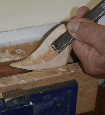
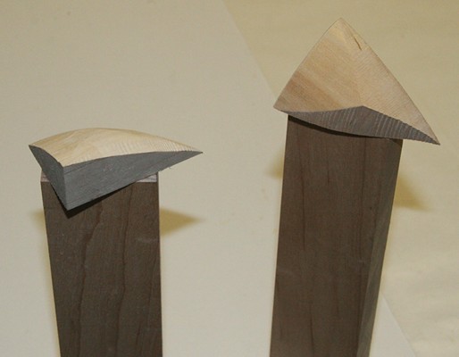
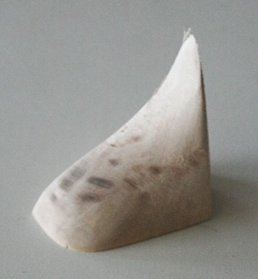
I don't have a tutorial but here are a couple pictures of how I went about cutting and contouring those items. I hope this helps. I first rough cut the block out of bass wood (you could use balsa) and carved some of the main contours. Then I used some 'hot glue' to mount them at the end of a stick so I could sand the part on my disk sander without burning my fingers. Obviously the final parts need a lot more work but that is better done after you install them and file them smooth along with the bulkheads.
-
The history of this ship is very interesting. In particular its last days in San Francisco before it was sent to Olso where it was 'rebuilt'. Note the last paragraph in the following article http://oceanbeachbulletin.com/2011/09/27/before-now-the-gjoa-through-the-northwest-passage-to-golden-gate-park/ If this is true, the items you refer to are probably copies and you might get a lot of information from the Fram museum in Oslo. Somebody there did a lot of work.
-
Tom, you and i (and lots of others here) take and show lots of good pictures of our progress. There is an old saying about a picture . . .. But I really think for our logs it is important to keep those visuals going all the time. I even post some for my own interest (even though they may not be to others). I refer to some of those old pictures many times as I go along. I have gotten to a point where I have a separate folder (and sub folders) for all I do on this modeling thing. What I do, though, is to save each picture reduced in size so they don't take up tons of space. I probably am preaching to the preacher. Your model is really interesting and you are doing a great job. Keep it up.
- 1,350 replies
-
- 3
-
-
- constitution
- model shipways
- (and 1 more)
-
if I were to get another vise, I would also consider the Panavise 301. It is simple, easy to mount (don't even consider the vacuum type), and you can readily change the jaws if and when they get worn.
-
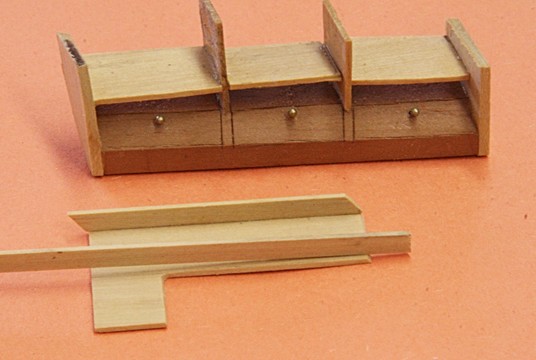
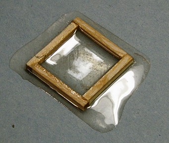
Jud and Dave, here is the result of using a casting resin to represent the water. I had no idea how much to pour in because the front was covered with glass and a large clamp to seal off the edges. I toyed with the idea of adding another layer, but I am afraid that might end up a disaster. Less than half a tank is better than no water at all. Notice the 'lead oxide' in the bottom . What will come much later is a 2 inch lead pipe going down from the hand pump on the berth deck. It just happened to be right in the front of this model, so I am going to give that a whirl. The two lines holding the barrels will be tied off on two cleats mounted on the center post (not yet installed). I am still working on the storage racks.
- 572 replies
-
- 12
-
-
- constitution
- frigate
- (and 1 more)
-
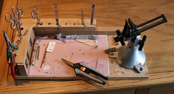
Jazzchip, the little vise I show has been around for a long time and I don't even remember where and when I got it. I even made a few changes (aluminum jaws instead of the old worn-out plastic parts), but it works fine for me. I suggest you browse to find a similar one. Obviously the base and tool holders can be anything you want. Here is another picture of a part I am working on right now. I can turn this anyway I want to get the right position. I should also mention that my working area(s) are not all that neat and there is a problem moving back and forth between my office and the garage (ask my admiral about tracking wood chips down the hallway).
-
Nothing new to post except a couple notes to myself. I decided to try casting some epoxy resin inside the 'swimming pool'. I always like to experiment before committing to the big thing. I kwow about release agents and happen to have a can of some old spray stuff. A piece of clear glass (coated) would do the trick. I made a small wooden frame, mixed some resin and placed it on the release coated glass. All worked great, the resin filled the square mold and it looked nice. But then something stupid happened (stupid on my part). The wooden frame simply floated to the top of the resin and . . . . . At least I know that sealing the edges is important. For the real 'swimming pool', I coated glass, sealed the edges with tape coated that with wax, and clamped the glass to the front. Then I poured . . . . It takes at least 24 hours before I can find out what happened. Meanwhile I am doing other things like making a lumber rack, mounting barrels (to be held in place by rope) and the cabinets towards the bow.
- 572 replies
-
- 7
-
-
- constitution
- frigate
- (and 1 more)
-
To come back to your original question, does the vise have to be 'big'? Since you are working on a table, how about a small vise that can be 'portable' and can serve several functions? Here is another picture. A bit messy, but you get the idea.
-
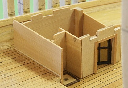
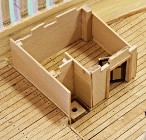
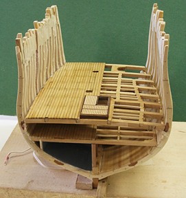
The orlop deck has two special store rooms. They had different purposes (sail room, boatsun stores, etc). I don't know what is in them at the present time, but here are the walls as I see them. When installed, there will be an LED inside and with the door partly open there should be light coming through the opening. I may have to do some sealing near the top of the walls so light does not leak through the rough slots (needed to clear the berth deck beams. I don't want to make shelves because they will not be visible, but there will be some trim along the corners on the outside. Notice the 'carpenter's walk'; the narrow passage between the hull and the side wall. It was intended for the carpenter to make his routine inspections of the hull. There would also be shelves here but not on this model. I am still debating about the shelves and cabinets in the storage area forward of this room. The little alcove you see with the hole in the center is not a Chinese toilet, it is one of the two entrances to the gun powder room below.
- 572 replies
-
- 10
-
-
- constitution
- frigate
- (and 1 more)
-
Right, Mark. Here is another picture for those who might be considering making a cross section mid-ship versus aft or forward. Obviously mid ship is much easier since the hull is almost straight and there is no need to taper the planks. The contours of the hull make a major difference in what is happening with the planking, frames, etc. And they all have to be in line (fore and and aft as well as sideways)
- 572 replies
-
- 8
-
-
- constitution
- frigate
- (and 1 more)
-
Ok Mark, the whole project is getting more complicated, but I am trying to stay on top of it. There are lots more things I have on the shelf (such as two more decks and all their details) and they have to go somewhere. The biggest problem with my approach is that the alignment of each deck is very important and the stairs will prove that. The more I glance at the front thus far, the more I tend to think of a large cut along the starboard side. There will be some outside planking towards the top so I can incorporate the channels (both sides); however I still want to have a look below. I think, that as I take one step at a time, and not rush, the details of each deck will come around. LEDs in the store-room??? What store-room??? More walls to create and install on the orlop deck . . .
- 572 replies
-
- 6
-
-
- constitution
- frigate
- (and 1 more)
-
Thanks George, but now you can see why I keep thinking about the side view and removing a lot of those beams, carlings and frames to get a better idea of what is inside.
- 572 replies
-
- 5
-
-
- constitution
- frigate
- (and 1 more)
-
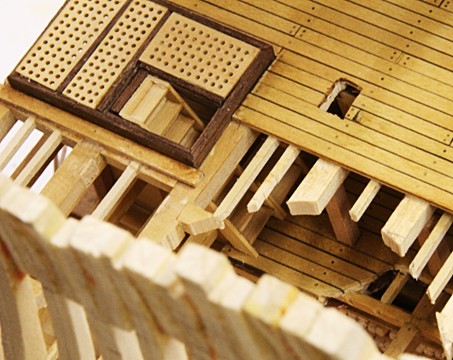
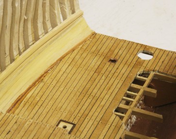
Berth deck cut to size. Again I made a template out of stiff paper, cut the shape and did some touch up sanding along the perimeter. The deck is still loose so I can work on the orlop deck, the walls and cabinets that fit along the wall in the forward storage room. But I needed the berth deck for height reference. There are several posts and walls and they should fit right. Including the fresh water tanks and the hold deck turned out to be more work than I had in mind. The earlier pictures of the tank did not show the flimsy walls (stiff cardboard painted grey) and the posts were just a tad too long, so the whole thing did not fit right. I ripped it all out and redid the walls using 1/32 inch boxwood. The orlop and hold decks are now glued in place. I also had problems with the ladders going up to the hold deck and berth deck. The alignment fore and aft is critical and I still have to do some juggling with the berth deck hatch and its hole for the ladder. When all of that is done, I will cut away a lot of the beam structure to show the inside. BTW the head clearance you see for the hold deck (below the berth deck) is just that; very small. It will be an area where barrels are stored.
- 572 replies
-
- 8
-
-
- constitution
- frigate
- (and 1 more)
-
Harvey, since you are from the Puget Sound area you would have to love Morro Bay. I has a quiet atmosphere with calm water to do some kayaking and paddle boarding and lots more. I used to live on a house boat on Portage Bay (before the current bridge across Lake Washington) and know what it is like to be on 'the water'. The admiral and I had a great time for this 'time out', including the long, but scenic drive along highway 1 from Carmel to Morro Bay (with a tour of the Hearst Cattle as well). But now it is back to the model. I still need to put some drawings together for the stairs but know that the angle will be somewhere near 65 degrees. More about this later, but I couldn't help myself but post an addition about using my mill to do so. The above is just for my reference on this log, but I do want to give Ken and Mark my thanks to the 'time out' post.

- 572 replies
-
- 4
-
-
- constitution
- frigate
- (and 1 more)
-
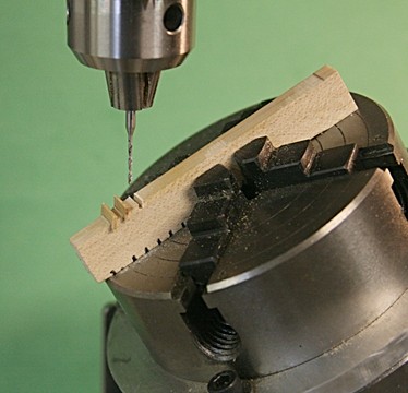
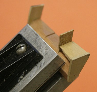
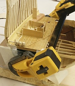
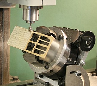
I mentioned that I had installed a rotary and tilting table on my mill. However, other than a trial run, I did not have any specific applications for their use until now. Here is one that I just came across: Making and installing stairs. In my cross section of the USS Constitution I encountered several stairs to go to the various decks. I am making all of them the same way, size and shape. (More about the 'making' later). However, the location will dictate their angle of installation. And it is this angle that led me to a situation where the raised part of the orlop deck needed to be cut at the stair angle. I clamped the 'hold deck' part in the four jaw chuck and rotated the table to the 65 degrees I needed. The pictures below explain the rest. Oh, in order to clamp this piece, I did remove two joists. but they were still loose and will be reinstalled later.
-
Time out! The admiral and I are ready for a little outing before El-Nino sets in and brings in rain (hopefully, in California). We are going to Carmel-by-the-Sea for a couple days, drive down highway-1 along the coast, spend a night in Moro Bay and visit some friends along the way. I am having some design problems with the stairs (little guy up to the hold deck and the longer one up to the berth deck). So it is good time to clear my mind, soul and body.
- 572 replies
-
- 5
-
-
- constitution
- frigate
- (and 1 more)

