HOLIDAY DONATION DRIVE - SUPPORT MSW - DO YOUR PART TO KEEP THIS GREAT FORUM GOING! (Only 72 donations so far out of 49,000 members - Can we at least get 100? C'mon guys!)
×


Modeler12
-
Posts
1,716 -
Joined
-
Last visited
Content Type
Profiles
Forums
Gallery
Events
Everything posted by Modeler12
-
 I thought about plexiglass like Mark suggested and I have used casting resins in the past. Both would require good detailing of the shape in order for the edges to look 'normal'. But I will give both more thought and a try here and there. Meanwhile I will keep the hold deck loose. Thanks for the suggestions and comments.
- 572 replies
-
- 4
-

-
- constitution
- frigate
- (and 1 more)
-
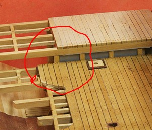
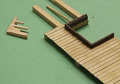
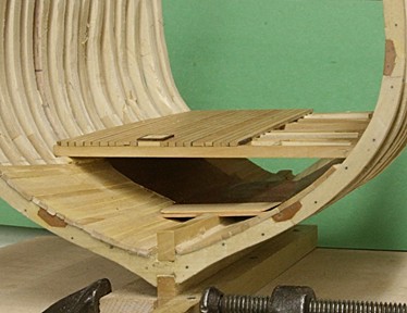
Here is the port side of the fresh water tank. Not shown are several support posts to hold the sides of this tank. The volume of water would result in a lot of pressure on those walls. I may show some of them along the starboard side. I could even notch the beam like I did on the port side and add a post there. The tree nailing of the hold-deck was done (as well as the back section of the orlop deck) but it still needs to be stained and finished. At this point it still sits there loosely waiting for the next step and I have not yet installed the baffles either. How could I show water in the tank?? BTW I have been concentrating so much about this view and almost forgot there is another side forward. I need to include the steps (up for both to the hold deck and the major one going up to the berth deck. So, having a loose hold deck is not all that bad. Here is what I was talking about. The steps need to be notched out of the hold deck.

- 572 replies
-
- 9
-
-
- constitution
- frigate
- (and 1 more)
-
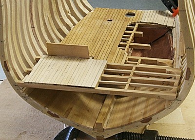
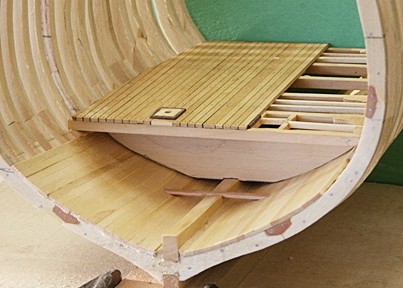
Not to worry, Mark. Cutting things out are not hard if they get in the way (both physically and mentally ). Here is the 'hold deck', loosely in place, before tree nailing and finishing. That little 'wall' you see might be the partition that separates the 'special store room' from the rest of the orlop deck. Just to the left of that will be the 'carpenter's walk'????? - more about that later. The 'fresh water swimming pool' in the basement goes next. But don't hold your breath . . . .
- 572 replies
-
- 10
-
-
- constitution
- frigate
- (and 1 more)
-
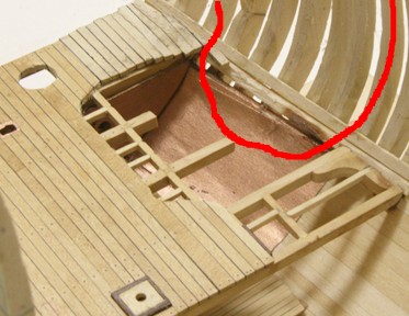
I know I am jumping around a bit, but when I installed a few more planks on the inside of the hull it occurred to me that the back part of the orlop deck needed a few more short planks. At what point do I want to cut away the part I don't want???? After all the work I put into this, it is not easy to cut it away. Some of it was because of a mistake, some because of bad plans and other simply because I had to in order to keep the 'flow of the lines'. I will be holding off a little longer until the berth deck is in place and the hull is more stable. At that point I will smooth the outside of the frames and chop away.
- 572 replies
-
- 7
-
-
- constitution
- frigate
- (and 1 more)
-
Right on Jud. If you have ever been on a cruise ship and tried to swim in a pool with choppy seas you get a ride of your life. Most of the time they empty the pool when things get too rough. In this case I will add baffles but I also need to keep the tanks tied together so you would not need to shift water from one to the other.
- 572 replies
-
- 5
-
-
- constitution
- frigate
- (and 1 more)
-
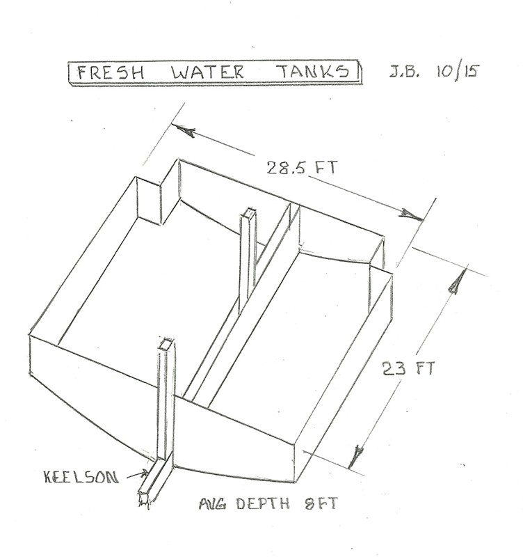
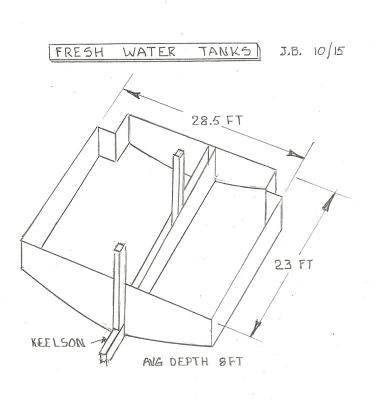
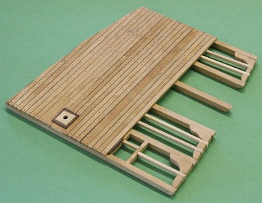
Well the orlop deck and powder room with LEDs is installed. So what comes next? I was going up to the berth deck when it occurred to me that it was there that we found the hand pump hanging from a post. Some research and lots of help from Dan and Henry let to a set of drawings that explained that around 1880 a fresh water system was installed and the hand pump could deliver fresh water to the oven. One of the drawings is shown below. It is not clear how many tanks fit in the area indicated and how deep they were. The lead lined tanks were removed probably towards the beginning of the 20th century. I took the liberty to design my tanks and do some calculations about how much water was needed and how deep the two tanks needed to be. I have no idea if this is correct, but I assumed that each person on deck would consume one gallon of water a day. Let's say there were 450 men aboard and there needed to be at least 60 days of water. That equates to 27,000 gallons of water. Assuming that the tanks would come up to the level of the orlop deck, the volume of the tanks shown below would hold roughly 30,000 gallons. Not much of margin of safety. So the tanks would go deeper than than that. If the tanks were on average 8 feet deep, the volume would be about 40,000 gallons. More reasonable. To do this the top of the tanks would need more beams and supports leading me to another series of planked deck which are about 20 inches above the orlop deck. That also jibes with the original drawing which indicates that there is a step upwards from the orlop deck to this new 'hold deck'. So here I go again. My model will stop right in the middle of these tanks, so the cross section will show water in the port side, while the starboard side still remains 'open' and the forward area (powder room and lights) should still be visible. On top of the hold deck on the port side will be barrels of food, a rack for lumber and other stuff.

- 572 replies
-
- 7
-
-
- constitution
- frigate
- (and 1 more)
-
Thanks George. I have also decided that the view above is good enough that I am cutting the front wall back to the center line. Instead of two crawl holes there will be only one in the port side. But it will be visible because I can also cut the wall to the hold back. I hope that makes sense. I have seen the details enough right now in my head. Those LEDs do show up nicely and I will install several in various places but only to provide space lights (unless I get brave enough to make some lanterns).
- 572 replies
-
- 6
-
-
- constitution
- frigate
- (and 1 more)
-
Ken, I painted the LEDs I have with some yellow and they look a lot better. When loosely installed they do give about the right amount of light in the powder room. So, I am going with that. I mentioned that I was thinking of adding a block of wood with holes to hold the LEDs. I did just that and bonded the block to the back of the rear wall where the holes line up with the 'portholes'. In addition the block has two holes on top that will line up with the slots in the orlop deck (the ones that Henry pointed out as being part of the light room) Hopefully that will cast some light in the sail-room. The back is getting rather crowded but after I cut the mast hole and the light room slots in the orlop deck, I am ready to finally put it all together.
- 572 replies
-
- 9
-
-
- constitution
- frigate
- (and 1 more)
-
Tyes, slings and halliards on a 1763 revenue cutter
Modeler12 replied to tkay11's topic in Masting, rigging and sails
When I saw this question it occurred to me, just like Henry mentioned, that the sling is 'temporary' and that, when the yard needed to be lowered, the halyard would raise the yard a bit so the sling could be slipped over the back side of the mast. The main yard would seldom be lowered to the deck unless damaged, in which case the sling would be cut.- 4 replies
-
- 3
-
-
- cutter
- Sherbourne
- (and 3 more)
-
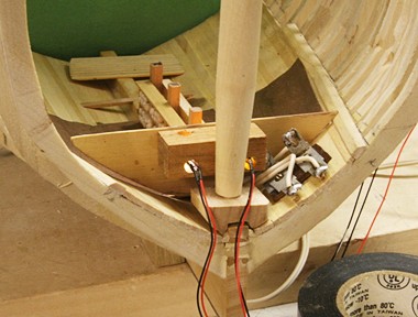
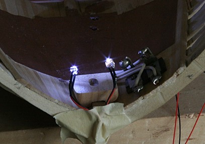
Once I decided to drill the hole through the keelson for the main connection below the stand, I figured that two of the LEDs for the powder room lights would also be right there. Hence having the connections where I put them. But then it occurred to me that having a 'bus bar' lead going underneath the floor and then out between the port frames was better than a bunch of individual LED wires. Just like you said. The connections there can be done anytime before I plank the outside hull. It is awfully warm in my garage right now, so I played around in my office with the LEDs I have for the powder room. The type I bought are very bright and I may have to add some white paint to dim them. For now I will leave them until I have installed them in the wall (yet to come). However, I am also toying with ways to hold the two in the 'light room' so they shine through the porthole as well as up into the sail-room (through those two rectangular openings in the floor, as Henry pointed out). Right now I am thinking a small block that can be bonded on top of the mast step block with a hole in the back for the LED wires and a slot on top for the sail-room opening. They would be aligned with the port holes in the wall. I would still be able to pull the LEDs out (straight back) if I have to exchange them for a different size. Here are two pictures with the bright lights. Looking at the back it is not too bad, but a head on shot is glaring. I need to order more LEDs and consider getting some of the nano lights with a soft white color.
- 572 replies
-
- 8
-
-
- constitution
- frigate
- (and 1 more)
-
I tend to agree with wq. Shot would be better stored below deck as low as possible for extra ballast. When readied for battle the shot would be brought up and stored in the rack. What strikes me as odd in a couple of the pictures shown above is that two different sizes of shot are in the same rack. Talk about mass confusion when loading the barrel during the heat of battle!!!
-
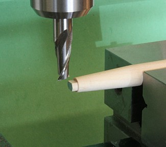
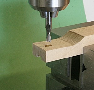
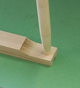
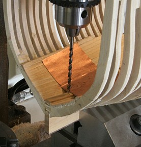
Stepping the mast I first tapered the mast section that is below the gun deck. Then I milled the end as shown below. Using a piece of birch, I milled a 1/4 inch wide slot that would fit across the keelson. Then I cut the key slot to fit the mast. Finally I shaped the block so it would fit inside the frames. I had to do some trial and error machining to make it fit. Then I cut it to length. Now that I look at the last picture, I realize that the block is too thick. No problem as long as I make the adjustments before it is glued in place. The mast will not be glued at all. It needs to be removed several times as the other decks go on.
- 572 replies
-
- 11
-
-
- constitution
- frigate
- (and 1 more)
-
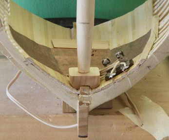
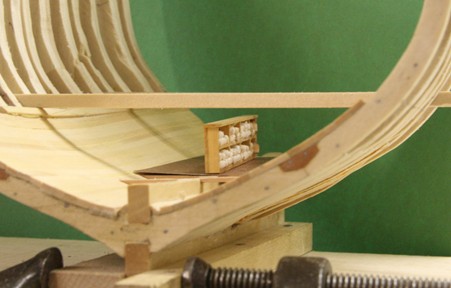
The chicken was just right (according to the admiral) and the brussels sprouts ok, while the fresh string-bean salad with olives was marginal. Maybe some ice-cream later will help. I have changed my mind about the LED terminal. I will still use the one I showed above for the two 'light rooms' (they are right next to this point). But for the others I added a line that ends up along the port side between frames. From there I can easily connect LEDs where I want them (rather than having all those little guys dangling as I proceed with the rest of this monstrosity). In either case the wires will not be visible. If some belong back or forward I can simply cut a small groove in the frames for the tiny wires. Meanwhile I cut a template for the aft wall that has the two holes for the 'light room' -not yet cut out. Will it work????? Will there be enough light?? Who knows? Maybe tomorrow. BTW the three posts you see are glued to the back of the cartridge shelf. This gives me a perfect reference and a nice 'resting place' for the center of the orlop deck.
- 572 replies
-
- 9
-
-
- constitution
- frigate
- (and 1 more)
-
Thanks Bob. I do go on as time permits. Right now I hear a timer and the baked chicken is done. Will be back with more.
- 572 replies
-
- 4
-
-
- constitution
- frigate
- (and 1 more)
-
Blackening brass is not that difficult and I would suggest to do that rather than paining, etc. For a few bucks you can buy patina from a hobby supply store that handles stained-glass items. It even comes in different colors besides black and it works on iron, copper, and other metals such as the casting stuff (brittany??) For blackening brass wire I would highly recommend that you remove the clear coating that is applied to wire to keep it shiny. Some steel wool will do it. I always do this on a large section of the spool. This also helps if you do any soldering, brazing or bonding with epoxy or CA.
-
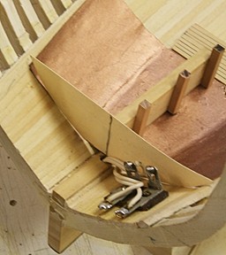
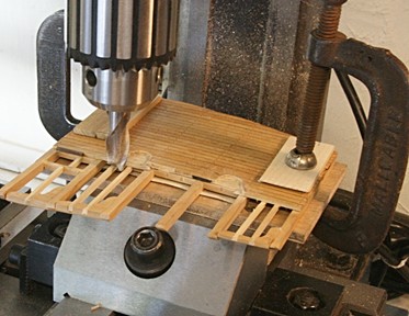
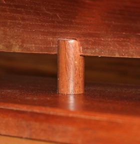
I figured that there are two ways to provide more light below. One is to install LEDs, which I will do. The second is to open up the orlop deck. The picture below shows how I used my mill to carve away some of the planking. I took it right up to the king plank at the center line. There will be posts on top and below this plank, so I did not want to go any further. By doing this the structure also becomes more visible. The cable for the LEDs goes through a hole I drilled through the keelson. The various LED wires will come together here and the whole thing will be covered with the orlop deck. The wires to the LEDs will be buried underneath the powder floor and then down between the frames where needed. I will still have access to the terminal from behind. There is still room for the large block where the mast steps. The hole through the keelson will line up with one of the two supports that will be made of mahogany dowel (just like I used on the full scale model).

- 572 replies
-
- 12
-
-
- constitution
- frigate
- (and 1 more)
-
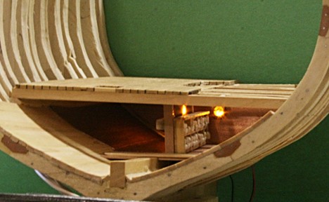
Go for it George. It is a lot of fun learning, doing and seeing the results as you go along. I keep thinking about various aspects of this project as I take my morning walks or rowing routine. Better than watching TV. Here is an example of why I want to add some LED lights.
- 572 replies
-
- 10
-
-
- constitution
- frigate
- (and 1 more)
-
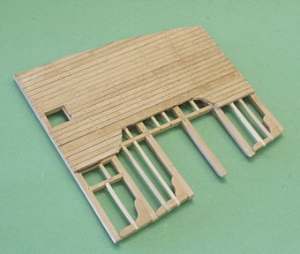
The problem is that this would not be visible when the walls below the orlop deck are added. Here is the first of two walls between the front of this model and the powder room. It still needs the cutouts for the passage in and out of the room. To show the rest, the wall will be cut away as needed. All is still loosey-goosey. My concept all along has been that (when finished) this thing would be displayed at an angle - not straight on. Hence, the finished parts to port and the details along starboard. But I may cheat here and there.
- 572 replies
-
- 10
-
-
- constitution
- frigate
- (and 1 more)
-
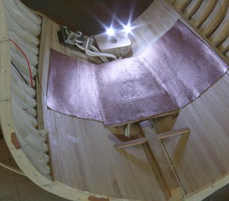
Now that the inside planking is done, I was able to trim the orlop deck to fit where it is supposed to go. I also finished installing carlings and lodging knees. I had to remake the knees for the new beam sizes and spacing, but I left out two knees and carlings where the frames will be cut later on. The floor of the gun powder room is supported by beams and is covered with copper. Here that is simulated with copper painted board. This now gives me the locations for the walls of the powder room. Earlier I mentioned that I might have to lower the shelf that holds the cartridges. Now it looks like there will be plenty of headroom, even with copper sheeting on the ceiling of the powder room.
- 572 replies
-
- 12
-
-
- constitution
- frigate
- (and 1 more)
-
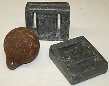
Indeed those are two lead diving weights (from my SCUBA diving days long ago) and the ball was left over from salmon fishing off the coast of San Fran.
- 572 replies
-
- 5
-
-
- constitution
- frigate
- (and 1 more)
-
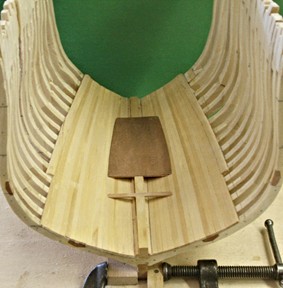
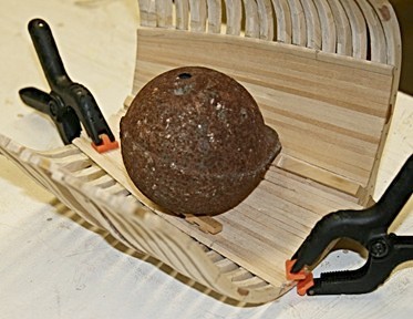
I did the same with the port side. In order to hold the center part of each plank down while gluing, I use various clamps and dead weights (along with some shims). I wonder how many of you recognize the two types of weights I show below. I did use the lead weights but never caught anything with the iron ball.
- 572 replies
-
- 9
-
-
- constitution
- frigate
- (and 1 more)
-
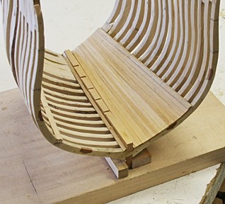
The first section of the inside planking is done. This is where the starboard side stops. In fact some of the planking (and frames) towards the middle part will be cut away to show the gun powder room (yet to be installed). The plank just underneath the clamp had to be 'custom fitted', but it all came together alright.
- 572 replies
-
- 8
-
-
- constitution
- frigate
- (and 1 more)
-
Beats me, David. It has been in my garage even before we had a garage. The only marking is in the casting 'Made in USA'.
- 572 replies
-
- 3
-
-
- constitution
- frigate
- (and 1 more)
-
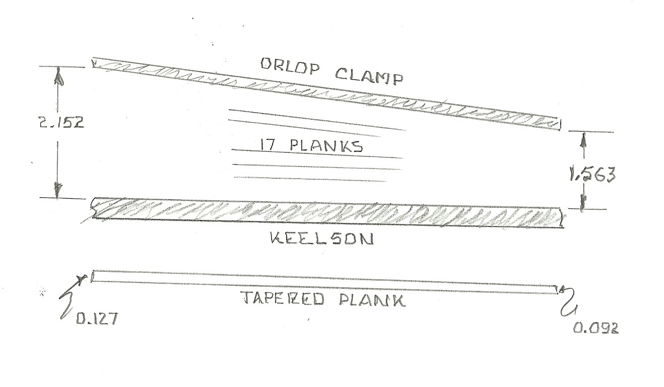
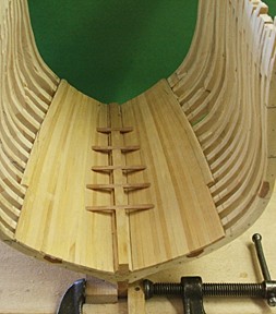
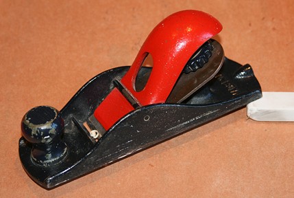
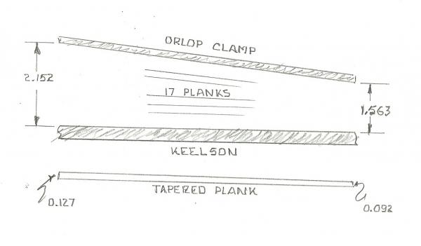
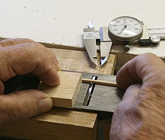
Tapering planks After the keelson and the two 'clamps' were in place, I took two of the planks and beveled them so they would fit against the keelson at an angle. They were glued in place one on each side of the keelson. Marquardt refers to them as 'lose limber planks'; mine are not lose. Now I was ready to measure the distance from the keelson to the clamp and see how many planks I needed. I am using some basswood that was ripped to about 0.131 inches. The sketch below shows that I needed 17 planks tapered from .127 inches down to 0.092 inches. I simply divided the measured distances by 17. To taper the planks I used a small block plane mounted in a vise. The wooden block is to keep the plank from rotating. The dial caliper was used to measure both ends and some sandpaper helped to smooth the rough edges. The third picture shows two planks before and after tapering.

- 572 replies
-
- 11
-
-
- constitution
- frigate
- (and 1 more)
-
Interesting. I particularly like the Polish ending: "the sun went down at noon" referring to the scuttling of one of the Swedish ships, the Solen. So, Nirvana, this new wreck was not found 'yesterday', but many years ago. I assume you found out about this 'yesterday'. Just like me, finding out about it from your post today. Thanks you.