HOLIDAY DONATION DRIVE - SUPPORT MSW - DO YOUR PART TO KEEP THIS GREAT FORUM GOING! (Only 66 donations so far out of 49,000 members - Can we at least get100? C'mon guys!)
×


Modeler12
-
Posts
1,716 -
Joined
-
Last visited
Content Type
Profiles
Forums
Gallery
Events
Everything posted by Modeler12
-

Question about stoves and how the rotisserie worked
Modeler12 replied to Modeler12's topic in Nautical/Naval History
Your example reinforces my whole concept. Turbochargers operate on the basis of lots of hot air going through the propeller (impeller) at high speed and lots of volume. This does not compare at all with a simple chimney and the upward flow of air coming from a fireplace. If an impeller were to be installed in your fireplace and it should become over burdened, the effect would be like a damper being closed. And you know where the smoke and fumes would go? Rob, you and others keep telling me that the contraption was used all over the seas and on land and I am waiting to see proof of that. Do you have a print, painting or photograph of this? The example of the museum stove for the Victory is the first I have seen. Thank you. I am not saying rotary spits were not commonly used at sea. But they were probably operated by one of those young boys turning a crank. -
I'll finish the stove, Steve. You find a turkey small enough to cook on it. But the stove will not have that rotating contraption that will not work.
- 572 replies
-
- 3
-

-
- constitution
- frigate
- (and 1 more)
-
Question about stoves and how the rotisserie worked
Modeler12 replied to Modeler12's topic in Nautical/Naval History
Having a patent does not mean that the proposed system actually works. However, if such a system was actually installed and operating in houses is an interesting side line and I would be interested in seeing any diagrams and pictures showing this. I still maintain that a childish looking fan that rotates due to hot air passing over its blades cannot and will not produce enough energy and torque to drive gears and pulleys to rotate roasting spits. The amount of air and its velocity would have to be tremendous to do so. Besides the design leaves a lot to be desired if the exterior shaft comes out horizontally and the fan drives its shaft vertically. That involves more gears than necessary and its maintenance would be deplorable. If the device really worked, why was it taken away on the USS Constitution? Do other ships that remain have this feature? -
Question about stoves and how the rotisserie worked
Modeler12 replied to Modeler12's topic in Nautical/Naval History
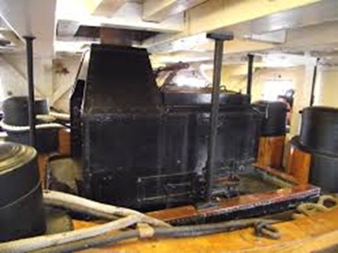
Thanks George, That confirms that at least in the last remod of the USS Constitution they did not include the pulleys and spit rods. In fact, I cannot imagine that the spits were used on a regular basis at sea. How many goats, chickens and pigs does it take to feed an army for a month or more? An open grill with pots and pans would be more likely being used for the officer's meals. The coffee pot is a real winner. Notice also that the chimney has no 'chamber with fan'. It goes directly into the stack. -
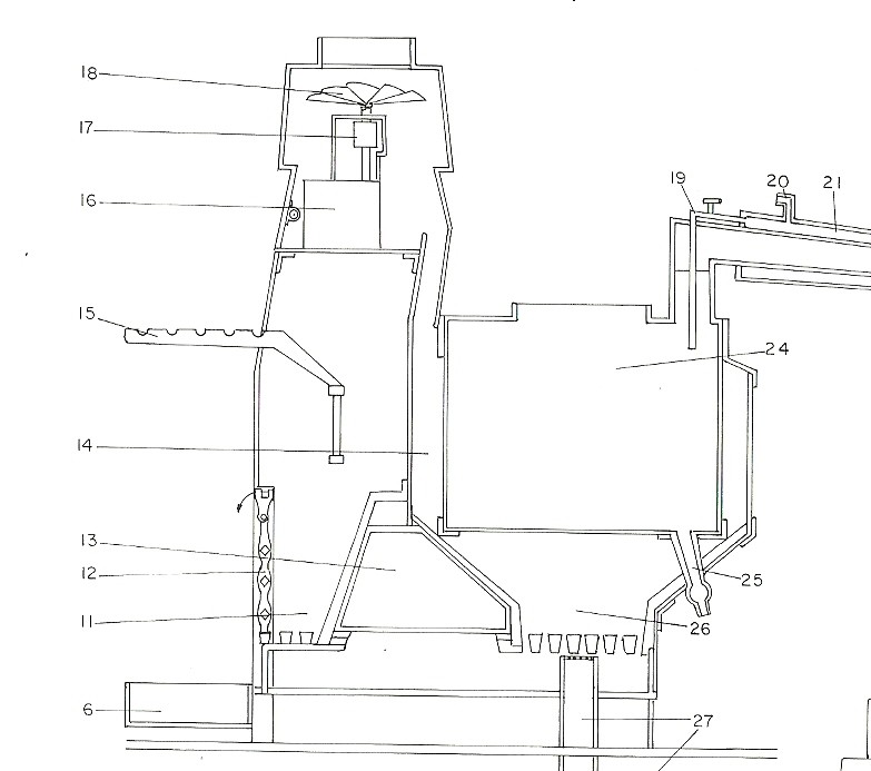
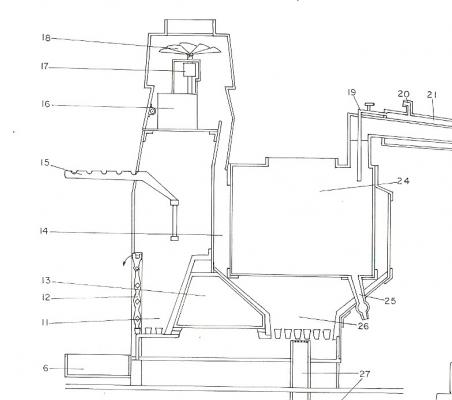
There are several beautiful models of ship stoves I have seen that are made to scale with great details. Indeed there are several pieces of literature I have seen that show the same thing: The pulleys and chains that drive the spit rods in front of the stove. But did that actually work???? The idea was (and I don’t know if that was the inventor’s thoughts or not) that the smoke and hot air rising up the chimney would rotate a fan that was coupled to the spits. Note item 18 in the drawing below. I say: nonsense. It takes a lot more than hot air to create the torque required to turn that rig (let alone the meat that would be on the spits). I think most of us have barbequed and used a rotisserie, and I know it takes some doing – by hand or an electric motor. Here are a couple pictures about the ‘fan’, etc. But they are drawings or models, no real proof! Does anyone know the story and history???
-
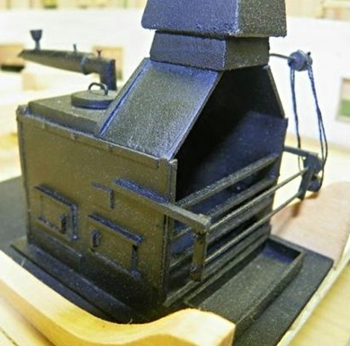
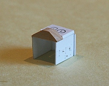
Well, let me retract that comment above. Here is a sneak preview. It is a dry fit with lots of trimming and finish work ahead. Before all is done and the little cube is painted black, I thought you might have a peek. Yet to come are the stove pipe with chamber on top of the triangular piece, the drip tray and then lots of corner details, spit rods, etc.
- 572 replies
-
- 7
-
-
- constitution
- frigate
- (and 1 more)
-
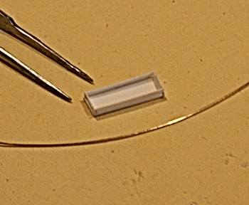
I am not going to show any more pictures of my attempts to make the stove, other than the following. It is my first try to make the drip tray (a bit wide, but that can be corrected). The length is about 0.60 inches, compared with the wire at 0.016 inch. There are a couple beautiful stoves made and published here on MSW. Both were made with brass and copper, but I am not very good with metals at this scale to do the bending, cutting, brazing, etc. So, perhaps the stove could be made out of the same material shown in the picture below; but time will tell
- 572 replies
-
- 4
-
-
- constitution
- frigate
- (and 1 more)
-
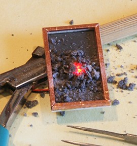
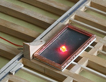
OK, Mark. While work continues on the gun deck planking (laying, nailing, sanding, etc.), I was curious how coal on top of the fire would look like. I have a long way to go with the stove, but I think some coal would diffuse the bright red. I found a piece of black lava, crushed it and will use that later inside.
- 572 replies
-
- 10
-
-
- constitution
- frigate
- (and 1 more)
-
Not to worry, Mark. In order for that little guy to go nuclear a lot more would have to be in place. And I am not only talking about logistics, politics, bureaucracy, and not to mention lack of 'control' by those who are supposed to have that ???? Please, don't get me started with this, but let me just mention that a 'fire in the hole' has nothing to do with this either. Nothing will happen, OK? I may get electrocuted, burned, BUT i will survive the LEDs experiment. Wish me luck, I guess. Just to add a footnote: I am not aware of any nuclear device as small as what you see sitting on my desk. But stranger things have happened!!!!!!!!!!!!
- 572 replies
-
- 6
-
-
- constitution
- frigate
- (and 1 more)
-
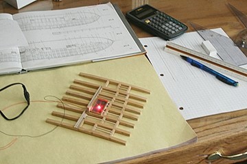
As long as I was looking at the area where the stove will go, I decided to make the platform on which the stove fits. The hearth is surrounded by a low wall covered with copper sheeting. So here is what mine will look like after the decking is all in place. Until then it is all loosey-goosey. It is a case where I will build a stove around a fire (instead of the other way around).
- 572 replies
-
- 7
-
-
- constitution
- frigate
- (and 1 more)
-
Thank you fellows. This is turning into a fun project. I was a bit curious how those heavy riding bits would line up on the two decks, but it looks like all is well in that department. It also gave me some ideas about the walls on the berth deck for the brig and sick-bay in the forward area. I have to admit that the doors for that may come from precast parts I received with the new rivets. It means painting which I don't like. Now I can take it all apart and continue with the planking of the gun deck. However, I also have to make the platform for the oven and fit that between the aft bits. So, lots of work to be done. But the admiral just informed me that it is father's day and I should relax, go out for lunch, etc.
- 572 replies
-
- 5
-
-
- constitution
- frigate
- (and 1 more)
-
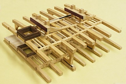
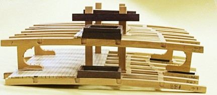
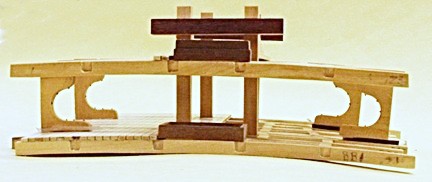
Be sure you have the time to do that. It is slow and easy. Could be done at work on a slow day, but in the long run it is worth the time (at least in my opinion). Moving along with the cross section decks and my question of the day: Will it work? I took the gun deck and berth deck and joined them. Below you can see that they should (dry fit with a bit of double backed tape to hold the C-knees on the berth deck). The first picture should confuse any one, but continue with the rest and you will see how there is lots more to be added.
- 572 replies
-
- 12
-
-
- constitution
- frigate
- (and 1 more)
-
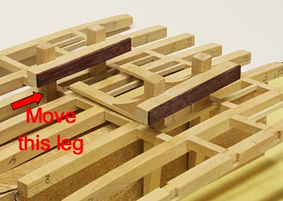
Problem resolved. Broke the riding bit, cut the main beam shorter and moved it so it fits between the carlings. Just received the order of more rivets from Itchy Train Group. Fast delivery, only a few days. Included were two packages of 'square nuts with washers'. If you have a microscope you might see the details, but for all practical purposes the rivets are good enough. Below is one of the riding bits for the gun deck with the nuts and washers installed. The picture is a bit out of focus and I will try to take another shot later. Sorry, I took another picture of the square nut and washer and still could not tell the difference. When I stare at it long enough I think I can see a nut. But maybe it is just me.
- 572 replies
-
- 8
-
-
- constitution
- frigate
- (and 1 more)
-
Here is one of those 'Gots-you'. I made such a careful point earlier that the large bits on the gun deck should not interfere with the beams below. And indeed I had to realign the carlings on the berth deck to make sure it fitted. Well, that was one, but what about the second one, towards the bow? The 'book' shows a slight change in width for the two bits and I just made both the same. Mistake. Now I have to see how I can correct my mistake.
- 572 replies
-
- 7
-
-
- constitution
- frigate
- (and 1 more)
-
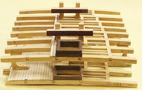
Thank you again, George and Keelhauled. I might mention, looking at the picture above, that the two open areas at each end are for a hatch cover to the left and the fore-mast towards the bow. Hence no ledges across those spaces. I also found that leaving the hatch frames off until later gives me more room to sand the deck planks. I should have done the same with the orlop deck. Some times I jump ahead too fast. Tomorrow I will show another picture of the berth deck sanded, stained, poly-wiped and (hopefully) finished. But it still will be interesting to see how the sail-room partitions and others, such as crates, barrels and other details, will effect the overall view. Much later!
- 572 replies
-
- 4
-
-
- constitution
- frigate
- (and 1 more)
-
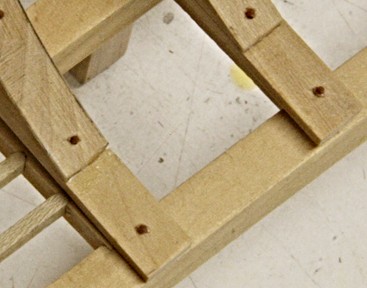
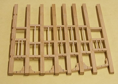
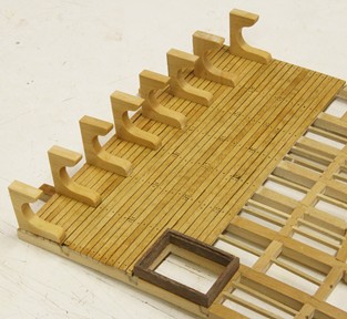
Here is the result: I should mention that the knees were giving me a bit of a thinking problem. Notice that they are alternating in orientation. I merrily went along and made them as before (all nicely in a row). Then I noticed my mistake, turned three of them over (and I still had the same mistake). The reason is that the bottom edge slants and that does not translate with a flip. The correct knees had to be redrawn and drilled, cut and sanded again. Obviously, - in the picture above - I still need to notch the new ones and add the ledges. So, now I have three more knees if anyone needs extra knees for some kind of transplant. But they are lefties and may walk a bit strangely. So, be forewarned. They also need rivets. BTW as before, I did not add the carlings and ledges on top (the port side), because that will all be covered with deck planking.
- 572 replies
-
- 12
-
-
- constitution
- frigate
- (and 1 more)
-
Have a look at this video:
-
Workshop Set Up Question
Modeler12 replied to ChrisLBren's topic in Modeling tools and Workshop Equipment
One thought about your first picture and the 'plumbing' on the studs. Is it possible to add a firring strip of wood on top of the studs so that the pipes are hidden? That way you could sheet-rock over them and have a wall to work from. I noticed in your third picture that copper pipes are coming through the wall and that could have been prevented the same way. -
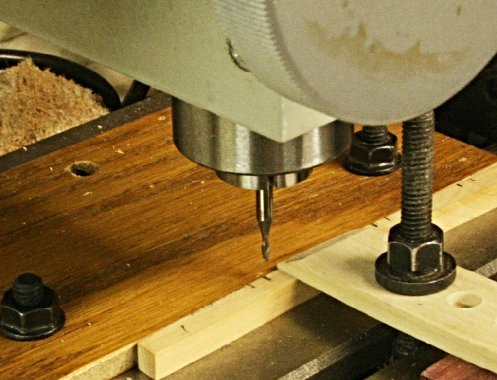
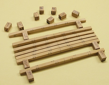
Because of my mistake with beam spacing, I am trying to be extra careful with the gun deck. I checked my drawings and they are fine. Then I made spacers to correspond to those measurements. They will help while clamping the beams together. This was also the time to mark where the carlings were to go (black pencil marks). Next comes the milling of the grooves in the beams for the carlings. Number one beam is mounted on the mill table. If I screw this up again, I quit.

- 572 replies
-
- 9
-
-
- constitution
- frigate
- (and 1 more)
-
Thank you Tim. When I considered doing a cross section of the full scale model I just finished, I looked at the kit. But since I have the equipment to do some milling, lathe work etc, I figured all I had to loose is some time and a few bucks in wood if I did it 'my way' and screwed up. Then one thing led to another and here I am. The frames have been rough cut and some assembled to the keel, but I decided to hold off with the rest until I have a firm grasp of all that is to come. For example the carlings on the berth deck had to be moved because of the large bits on the deck above. Then I decided to add LEDs to some parts and that meant going through the keel and up along the starboard side. I still need to do that. The powder room needs lots of details and sits right on top of the keelsom. So, I will continue with making the gun deck but will hold of with the spar deck until the frames are ok and the bottom decks fitted. At least that is my plan.
- 572 replies
-
- 4
-
-
- constitution
- frigate
- (and 1 more)
-
Thanks Ken. I have ordered more rivets already, but Grandline has lots of interesting stuff. When I get to making the oven, for example, I may look into some of their parts such as sprockets, etc. Another item is the window I made for the light room. My window panes leave a lot to be desired.
- 572 replies
-
- 3
-
-
- constitution
- frigate
- (and 1 more)
-
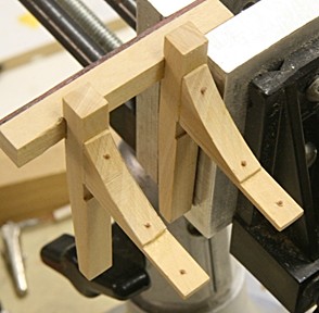
OK Mark, you all dared me and here I go again. I was actually a push-over for that on the playground. Besides that, I fell through the ice, fed a giraffe at the zoo with food between my lips, toasted mothers while in Belarus drinking vodka, etc. But that was much later. Below some C-knees lined up like 'pacman' and the little guy to be cobbled up. Actually it is my first try for rivets in the lodging knees. Now I have to spend more money on rivets I had some left over, but that is not enough if I am going to do this all the way around. I also need more drills (broke one and I am on my last one). Thanks guys!!!
- 572 replies
-
- 6
-
-
- constitution
- frigate
- (and 1 more)
-
OK JS, so if the admiral thinks I am a bit slow, I can blame it you. I hope I don't break too many drills and that I don't loose all those little brown guys. BTW the shaft diameter of the drill is not 1/8 inch, it is 0.091 inches and does not fit the collets I have for the mill. Otherwise it would be a lost simpler. The large heads you see in the photographs are not really rivets. They are nuts on top of long bolts, I believe. The place where I got the rivets also makes nuts with washers at the end of a bolt. That would have been nicer but I don't want to bother ordering those. https://www.tichytraingroup.com/Shop/tabid/91/c/ho_nbw--rivets/Default.aspx They are referred to as NBW.
- 572 replies
-
- 3
-
-
- constitution
- frigate
- (and 1 more)
-
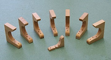
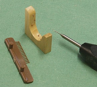
Thanks Ken and Grant. I have seen the decals but never tried them. I did try the adhesive with black paint idea and that just was too hard to control. I used a round toothpick and pre-coated the wood surface, but it did not look right. Not enough raised definition. Since you guys talked me into it, I went back to the rivet idea. This time I used a 0.5 mm drill with 1/8 inch shaft that allowed me to get inside the curve. But I did have to use a pin vise. Slow work, but it seems ok. I still need to glue the rivets in place with a tiny dab of Titebond.
- 572 replies
-
- 6
-
-
- constitution
- frigate
- (and 1 more)
-
One more picture for tonight. It is my first try to sand the berth deck with all its ups and downs and then stain it with some water-based stain (my favorite). The C-knees are more or less in position to give the whole thing some perspective. However more sanding and corrections are in order. Good night for now.
- 572 replies
-
- 4
-
-
- constitution
- frigate
- (and 1 more)