Modeler12
-
Posts
1,716 -
Joined
-
Last visited
Content Type
Profiles
Forums
Gallery
Events
Everything posted by Modeler12
-

Micro Drills, Revisited.
Modeler12 replied to Modeler12's topic in Modeling tools and Workshop Equipment
Your idea is not all that far fetched. I inherited (among other things) a large box full of drills from my father-in-law. He had a die-casting shop where they made their own dies. The machinists would replace a dull drill rather than sharpening it. My 'source' of unsorted bits took a while to sort, but, after sharpening them, I had a pocket full of nice drills. Of course, most were larger than the #60's and up. Is there a machine shop in your area? PS Drill bits are notorious for having unequal cutting edges. If the center is off a tiny bit and one edge is wider than the other, . .guess what? A bigger hole than wanted. In addition, the cutting edges have to be standing out, meaning the back of each edge should be lower. If not, it won't cut and maybe burn a hole in wood. Here is a quick video about this. http://www.gia.edu/gia-news-research-bench-tip-01 -
Because for this purchase I used a card that was never used on-line. But then again . . . .????
-
Jud, it is my understanding that to change the hardness of these bits you first have to anneal the metal and that is at a temperature well above 400 deg F. Three to four hours in a kitchen oven is not going to do it. I have just ordered some of the 'cheap' bits and will let you know what gives. . . . . Of course, delivery is not going to be quick. They probably ship direct from Asia somewhere. Total cost about four dollars. But now they also have my credit card number . . . .????
-
Thanks Frank for your pictures and explanation. Marvelous. I was not aware that Dremel makes router bits in the various shapes. So, I took a look at what is available and I was surprised. Dremel, of course, sells their own brand and they look very nice. A set of five runs about $30 US. But what shocked me were the sets from China, Hong Kong and Malasia for as low as $3 for a set of ten. Now, I grant you that the quality is questionable, but at that price I am going to give it a go. Here are some links: http://www.ebay.com/sch/i.html?poi=&adpos=1s5&ul_noapp=true&geo_id=10232&MT_ID=70&crlp=79516278875_857&keyword=dremel+router+bits&rlsatarget=aud-150920456644%3Akwd-117020436&_nkw=dremel+router+bits&device=c&crdt=0&treatment_id=7&clk_rvr_id=894839254983 http://www.toolbarn.com/dremel-tr770.html?gclid=Cj0KEQjwjrqvBRD6wf2fy-C61PIBEiQAUzKQTrf6ULwRsu1UiUtVU4i5sCh2b8smnM4A5BnUJ2SiN5waAmdZ8P8HAQ&ad=54711642134 One more thing about diamond coated bits. My trial run shown above was made with a piece of bloodwood and that may not have been fair. I know that it contains more than the usual amount of oil and tends to burn readily (like oak and other hardwoods). But even running the same tool through a piece of basswood caused some burning (10,000 rpm). Your pieces look great by comparison. Nice set up, Frank.
-
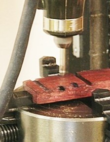
Frank, i just had to find out if the speed of the diamond coated tool has anything to do with cutting clean slots. I took my old dremmel-like tool, mounted the same diamond coated T-slot cutter, and the same piece of wood, and ran it at about 10,000 rpm or so. It burnt a pathway with lots of smoke along the way. The view is of the same piece as before, but form the other side. Sorry, but for wood I am still a believer in cutting chips rather than burning my way through.
-
Frank, your are lucky to have friends in the jewelry business and get all those nice bits. Have you used any of them on wood? Any suggestions about cutting details (speed and feed) to minimize the burning? I am sure those bits were designed for cutting metal. I really like the way you milled the slot/groove in the keel as you showed very clearly in those pictures. It is nice to be able to use all the tools you have available. Two vises for the mill is certainly helpful. Most of the time we need to improvise with what we have on hand and figure out a way to go from there. You showed us a nice adaptation.
-
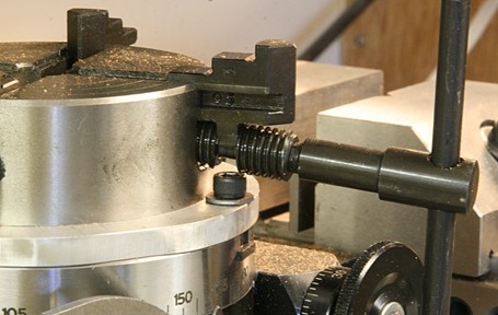
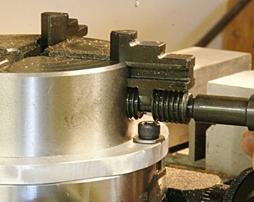
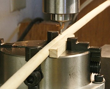
The topic is about tips and techniques. So here are a couple ideas about using the four jaw chuck (on the rotary table in this case). The question was raised about reversing the jaws on the chuck. On mine you can do that by unscrewing the jaw until you can lift it off the saddle in the crew. Don't take the screw out all the way and try to reverse the whole thing. Most likely the other end of the screw does not have a hole for the handle/key. After turning the jaw around, screw it back into the slot. The four jaws don't necessarily have to be all in the same position. Below are a couple examples how I mounted a long dowel so I could mill a slot down its center line. I am using only three of the jaws in this case. The second one uses all four jaws to hold a flat piece so I can machine a circular groove towards the tip. I only use this for light passes on wood. You might think of this as using the chuck as a vise.
-
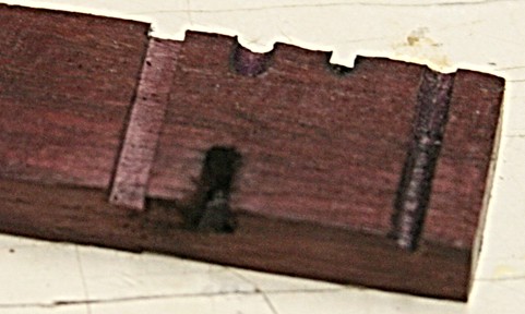
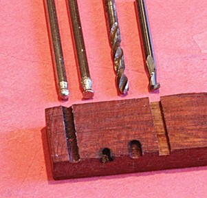
Chuck, I ran a quick experiment with those 'diamond coated bits' versus a real end-mill bit. The wood was a piece of bloodwood and the 'bits' included a short 1/8 inch diameter drill bit (just for fun, but not recommended with tiny drills because of breakage). The ball 'cut' through after two passed, but the T-slot bit just burnt and created some smoke. Same with the drill bit. The end-mill bit clearly made some chips. All were run at about 4000 rpm. The results are shown below. I still want to grind one of those old drill bits and see if I can make it work (make chips).
-
Adding accessories to your milling machine
Modeler12 replied to Modeler12's topic in Modeling tools and Workshop Equipment
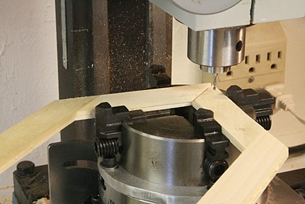
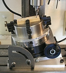
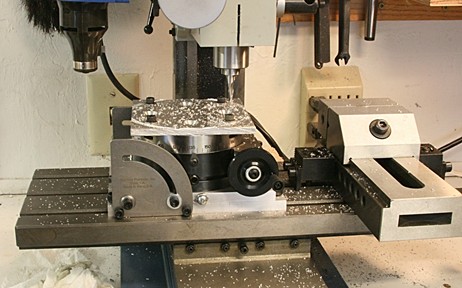
I decided to experiment with my new, modified toy and see how things worked out. Good thing; I found a couple hick-ups. Below you can see the small wooden block mounted on the rotary table using the four jaw chuck. I cut some grooves horizontally and then tilted the table as you can see in the pictures. A couple problems: 1. Mounting the chuck directly on the tilting table (using the adapter plate) is tricky because of the graduated angle pieces. The unit also sits too low so that I cannot tighten the jaws with the wrench provided. Mounting it on the rotary table took care of that. 2. The cap screws in the far right bottom corner hold the table to the mill. But I did not leave enough clearance when tilting the table. I need to take the unit apart and cut away some more metal. 3. My intent is to leave the chuck mounted on the adapter plate. However, as you can see, the cap screws that hold the plate to the rotary table interfere with the chuck jaws. Now I need to mount the chuck first with the jaws closed and then mount the work piece I should have made the holes in the adapter plate rotated -let's say- 30 degrees off center. That way I could close the jaws any time before or after. I can remedy this by making new slots or new countersunk holes in the adapter plate.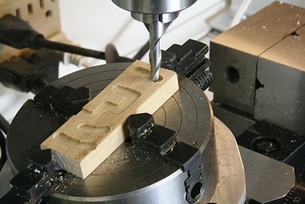
-
Adding accessories to your milling machine
Modeler12 replied to Modeler12's topic in Modeling tools and Workshop Equipment
Indexing blocks are a clever way to go. Turning the vise sideways is also a nice idea that may come in handy when milling tall parts that need to be clamped in the vise. Until I really get used to working with my mill a lot more, I think the rotary table and its very nice angular graduations will suffice for indexing. -
Adding accessories to your milling machine
Modeler12 replied to Modeler12's topic in Modeling tools and Workshop Equipment
Thanks for the link, Frank. At this time I don't want to spend another $200 for the Sherline attachment. At first glance it seems a bit complicated compared with the normal dividing plates. But until I really need to do a lot of that kind of machining, I will hold off. -
The water level was way down and launching boats required a long drive down dirt 'roads'. But the water was clear and not too cold. Warm weather helped. Now that I finished the rotary table adapter for my mill, I have no excuse not to continue with my model project, right? Unless the admiral tells me differently.
- 572 replies
-
- 5
-

-
- constitution
- frigate
- (and 1 more)
-
Thanks Dan, but all is well (relatively speaking). I had a mishap on Lake Shasta when I went flying around a turn at about 30 mph behind the ski-boat and skidded along the water surface for about ten feet, or so. I came up smiling; no broken bones, but nice bruises (with loud applause by my grand kids on the boat). I grinned and afterwards got lots of 'treatment' and comments from my dear wife. At 78 I am still their hero. I am still involved with my cross section, but have taken a bit of a diversion with my 'tools'. Namely, the attachments to my milling machine. Now that I have finished what I wanted for the mill, I will get back to the cross section (slowly) I am adding more of the frames and that is slow going. Lots of adjusting and sanding. My frames are quite wide (or thick?) which is good for all the miss-alignments that need to be taken care of. I hate sanding.

- 572 replies
-
- 6
-
-
- constitution
- frigate
- (and 1 more)
-
Tiny fake nails/nail heads
Modeler12 replied to Landlocked123's topic in Metal Work, Soldering and Metal Fittings
Sorry about my snide remark. Looking at all those details, John, I know this is not your first. Fabulous work!! Square nails or not, your brass parts are excellent. I am following your log. -
Adding accessories to your milling machine
Modeler12 replied to Modeler12's topic in Modeling tools and Workshop Equipment
Good idea, but I don't know if Sherline makes the dividing plates (and their conversion to the rotary table). Or am I missing something? On hind sight, Little Machine Shop makes a rotary table and offers a couple dividing plates that might come in handy. But again, how often do you need the kind of accuracy a dividing plate has in our modeling? Hand cranking to a scribed mark is still ok for me . The main question I still have is: to stay 'metric' or be able to convert? Of course that has been a major political problem here in the US. It is a bit like using the 'chip' in credit cards (that is finally being used by many merchants and customers here). The US is a bit slow along those lines!!! There are many good stories about that, I am sure. -
Adding accessories to your milling machine
Modeler12 replied to Modeler12's topic in Modeling tools and Workshop Equipment
That's one reason I got the tilting table ($110). It makes it easier to mount the rotary table to the mill bed and also serves me well for milling parts at a bevel or some other angle. -
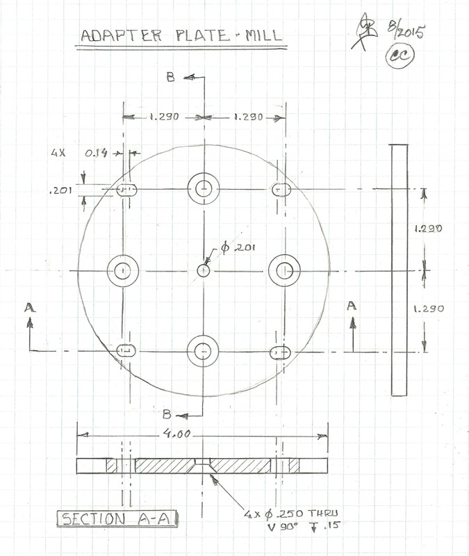
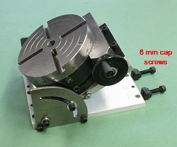
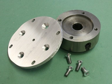
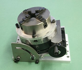
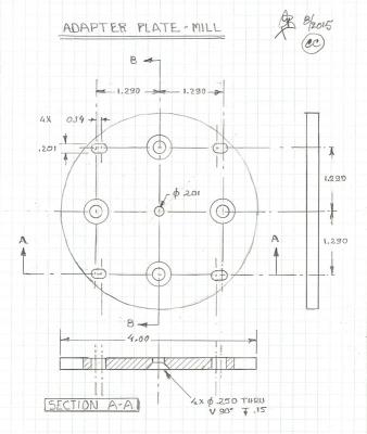
I have a mill made by Little Machine Shop. It is very similar to others such as those offered by Micro Mark, Harbor Freight and Grizzly, and - perhaps not in the same class - the Proxxon FF230. But just the same: they all have one thing in common: they use metric threads and that can cause some problems when interchanging accessories with those made on the basis of the US standard threads (for example Sherline). I wanted a rotary table for my mill: After looking at the various options offered by Grizzly (their ‘two inch self-centering vise’), and the rotary table sold by Micro Mark at a much higher price, I went with the 4 inch rotary table and tilting table made by Sherline. The rotary table is a high quality tool and the tilting table is ok, but nothing fancy. However, the combination of the two gives me a lot of possible machining options. I need to use metric bolts and T-nuts to hold the tilting table to my mill bed. But since the holes in the tilting base are US standard and don’t align with the mill table slots, I had to drill new holes in the tilting table base so it would. The four new holes are clearance holes for 6 mm cap screws and are spaced 1.78 inches apart. The rotary table is designed to clamp to the tilting table, so now I can use it without having to make new adapters to mount it to my mill table. So, far so good. How about chucks for the rotary table. You can buy them from Sherline, but I also have a mini lathe that has a three and a four jaw chuck. Again they are metric and that is where the rub lies. I don’t use the four jaw chuck very often and decided to make an adapter plate that would allow me to bolt the chuck to the rotary table. I used a ¼ inch thick aluminum plate and drilled the holes as shown in the drawing below. The countersunk holes are for the chuck and the slots are for the tilting table and rotary table mounts. The reason for the slots is that the hole-pattern in the Sherline table is all screwy and not spaced uniformly across the base plate. The two threaded holes used for the brackets to the rotary table could have been moved to 1.29 inches from center (the same as those to the right) instead of the 1.16 inch as it appears now. However, by having the slots, I can mount this new plate on the rotary table as well as the tilting table. Here are some possibilities: · Use the rotary table and tilting table for a wide range of operations without a chuck. · Mount the rotary table and tilting table along with one of the two chucks (three or four jaws). This is where the adapter plate comes into the picture. · Use the tilting table with a piece of plywood to drill holes or mill small parts at an angle (wood only). · To machine horizontal slots in shafts, spars or other parts I can take the tilting table (with chuck mounted) and tilt it to 90 degrees. Sherline makes a tailstock for their mill to do just that (it mounts on their mill bed, not mine). I like to keep my 4 inch vise where it is and I think I can make an adapter to serve as the ‘tailstock’ using wood. Besides, how often would I need that? Making the adapter plate was a nice metal working project and I got to use the rotary table for the first time. It worked great.
-
Proxxon EF vs. Dremel 7700
Modeler12 replied to rtropp's topic in Modeling tools and Workshop Equipment
They are so cheap, buy both and find out what is the best for your needs and likes. -
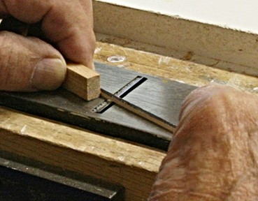
One more comment about using a small plane to taper planks. I dug out this picture when I was doing just that three years ago. i would like to point out that if you go this way, you should have some block or other way to guide the part. It is very easy to rotate and loose control of the sides. Watch your finger tips!!
- 1,354 replies
-
- 5
-
-
- constitution
- model shipways
- (and 1 more)
-
Tiny fake nails/nail heads
Modeler12 replied to Landlocked123's topic in Metal Work, Soldering and Metal Fittings
Another thread answered . . . . You are doing a nice job with your model, John. Square nails are tough. -
Design and Build a Custom Work Station
Modeler12 replied to pompey2's topic in Modeling tools and Workshop Equipment
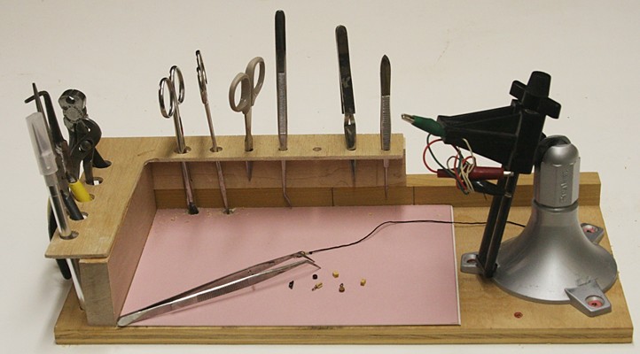
Here is my mini work station. It will fit anywhere you like.
-
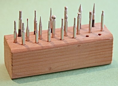
Chuck, you probably have seen these, but there are some diamond coated bits out there with a 1/8 inch shaft. I have used a couple of them and they work ok, not as good as a sharp bit, but at least there are several shapes to choose from. I am referring to the cone and cylindrical shapes. Don't bother with the straight bits.
-
Pin rails are a perfect example of drilling holes that are aligned and spaces just right. I might add one comment. My experience with building the full scale Constitution was not too good by mounting the pin rails directly against the bulwark with some glue. In other words they were butt joined and hard to keep aligned. Next time I want to make the rails wider and extend them into the bulwark and frames (if necessary). This could mean cutting tendons, something easily done on a mill.
-
I like to respond to a couple posts regarding using my mill for drilling. I understand that cranking the z direction feed can be a pain. I did not realize that some mills don't have the feature I have on mine. That is, with a simple push of a button I can change the z feed from cranking to a lever action such as used on a drill press. In other words I can readily change my mill to a drill press. In addition, I can mount a dremmel like tool on the head and use it for drills down to the #80 size while indexing the x and y according to my needs. Like most other operations with tiny bits, I just have to be more careful with the feed rate and not move the table while drilling. One example that comes to mind is drilling hundreds of small holes for tree nailing deck planking. As far as I am concerned, I agree with John that a Vanda-Lay mill seems like a waste of time and money when you consider its very limited capabilities.
-
Great work, Frank. And I find it interesting that you use the mill a lot. I just ordered the tilting table and rotary chuck from Sherline and am looking forward to doing some experimenting. I am sure it will take some time to do what you showed above. But it is all in the name of 'having fun with new toys'. Would you explain what a Sensitive Drilling Attachment is and how it works?