Modeler12
-
Posts
1,716 -
Joined
-
Last visited
Content Type
Profiles
Forums
Gallery
Events
Everything posted by Modeler12
-
 The first thing I did is make the keelson. There was a lot of controversy about this earlier. I saw drawings with different shapes depending on the time frame. Several of you provided me help, but in the long run I decided to draw up my own plans on the basis of what I learned back then. So, the keelson (not yet glued on) was notched for the small frames that support the copper bottom of the forward gun powder room. I hope there is enough clearance for the 'book shelf', but if not, I may have to cut the top part so it fits in the cramped space. The next strep is to install the first set of 'clamps' for the orlop deck and then fill the inside of the hull with planking. I already know that because of the hull shape, I have to taper some of these planks.
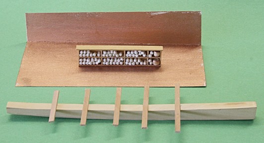
- 572 replies
-
- 9
-

-
- constitution
- frigate
- (and 1 more)
-
Thanks guys. At one time I put all decks together and it was scary indeed. Now I am going along with the assumption that a lot of the deck beams and some frames along the starboard side will be cut away to see the inside.
- 572 replies
-
- 8
-
-
- constitution
- frigate
- (and 1 more)
-
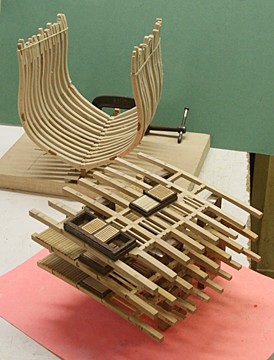
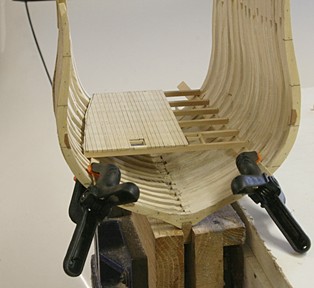
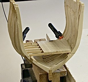
I think it is going to work! All along I have been wondering if my approach of prefabbing the decks would come together. Here is the orlop deck viewed from both ends. I need to do a lot of additional work with the keelson, clamps (the beams that support the deck frames along the hull), the knees, etc. The inside of the port hull will be planked and then the deck will be fitted again. Meanwhile I will be cutting and fitting the walls of the powder room and more details (including stepping the mast).
- 572 replies
-
- 9
-
-
- constitution
- frigate
- (and 1 more)
-
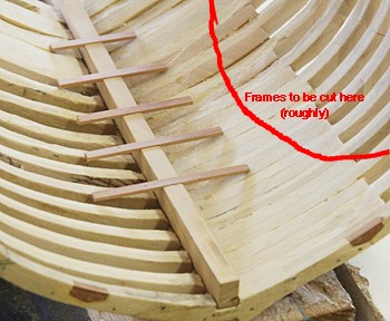
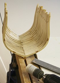
The frame works. It has been a while since I worked on the main frame. It was simply a matter of procrastinating while the inevitable was waiting for me. In the six inch long section there should be 31 frames, but I only will be showing (in part) only 16. Here they are attached to the keel with some of the 'in-between' frames partly shown. Towards the bottom there will be planking in and outside of the frames, nevertheless, there is a lot of filing and sanding to be done in order for this to look halfway decent. When the inside is done to my liking I will start the supports for the four decks and see how things go from there on. The outside of the frames comes later and I will not be concerned about that unless the frames get too thin as I am filing and sanding away . I also need to remember where the wires go for the various LEDs.
- 572 replies
-
- 7
-
-
- constitution
- frigate
- (and 1 more)
-
As the web site Frank mentioned, the most common alloy is 6061 and I am willing to bet that is what you used. All the others would have be bought from a special metals shop. When employed, I worked a lot with other alloys in the aircraft industry. 2024 for example was used a lot on the F-14 (Navy fighter) because it is also corrosion resistant compared with the others. 5052 was used a lot on skin panels, honeycomb and other structural parts. But again they are not your common Home Depot variety.
-
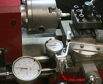
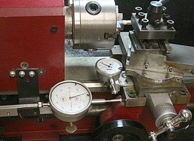
Thanks George and Frank. I am taking my time with this project, Frank, so you won't see a lot of progress shortly. As I am going along I get distracted easily with new ideas on how to use my tools the best way. Another example is the bracket for the mini lathe that holds the cross feed dial indicator. It is now a section of aluminum bar bent to shape and attached as shown below. The bottom part can be swiveled out of the way (with the wing nut) when I need to move the cross feed more than the 1/2 inch max for the dial indicator. There is also a 8-32 set screw marked 'zero adjust'. At any rate, for the last few barrels I used both indicators to locate and cut the grooves for the bands.
- 572 replies
-
- 6
-
-
- constitution
- frigate
- (and 1 more)
-
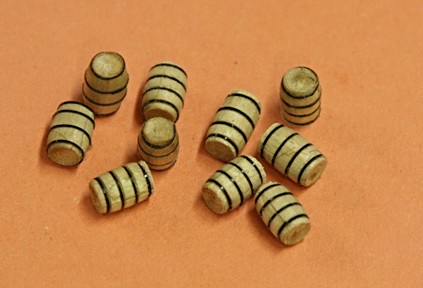
A few more and then it is onto something else. The main frame, perhaps.
- 572 replies
-
- 7
-
-
- constitution
- frigate
- (and 1 more)
-
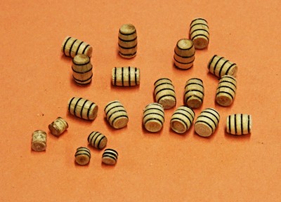
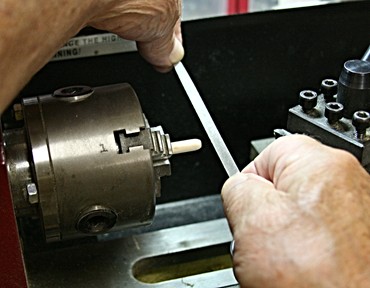
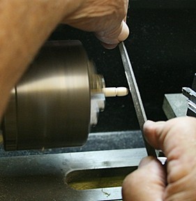
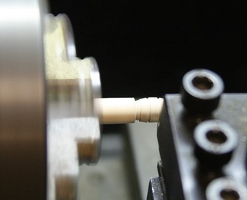
There is always a way to improve. In order to make the band spacing more uniform I decided to use my earlier modification by installing two dial indicators on my mini lathe. The picture below shows how the traverse head travel can be measured to the nearest 0.001 inch. -- I did not need to use the cross-head travel, so ignore the small dial indicator. It is perfectly safe where it is. To cut the grooves, (after shaping the barrel form) I position the narrow cut-off bit just to the left of the end. That gives me a 'zero' and will be the first band towards the end of the barrel. I cut the first groove, back out and move the head to the left using the indicator for an accurate position for the next groove, etc. In the case of these barrels I used a spacing of 0.090 inches. The two barrels to the far left were my earlier attempt. The others, I think, are more uniform. I need a few more of this size and then will make some more that are shorter and bulkier (like wine barrels). I do have a chart showing various sizes of barrels used in the olden days and will use that to 'comply'.
- 572 replies
-
- 12
-
-
- constitution
- frigate
- (and 1 more)
-
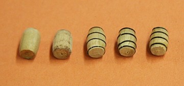
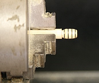
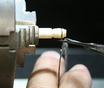
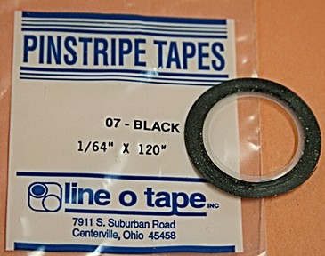
Barrels I was not at all satisfied with the powder kegs. The bands are too wide and look sloppy. So I decided to experiment with making barrels of a bit larger size. I will need several in the hold later on. Standard dowel is not the best choice but I went ahead and used 1/4 inch diameter for these trials. It is probably made out of pine. The main thing is that I wanted to use some narrow tape for the bands rather than painting them. Let me show you my various approaches and the final method I have settled on thus far. I have a small mini lathe (used but from Harbor Freight) with lots of attachments and cutting tools. I modified a cut-off bit and thinned it to 0.032 inch. I will use this later to cut some grooves for the tape. The black tape is 1/64th inch wide and, although it has some adhesive, it does not really stick that well. I ended up relying on the wet poly wipe to keep it in place (and even then it was a bit of struggle). Here are the steps. First I clean off the end of the rod and indent it with a simple turning bit. Rather than turning chisels I use a triangular file to round off the end and cut the groove to the length of the barrel. Both ends get rounded to my eyeballs. Nothing sacred. After all, coopers used the same eye balls. I finally settled on resting the tape inside a tiny groove as shown. This gives me much better spacing and more uniform looking bands. I may still modify this, but so far it works.
- 572 replies
-
- 10
-
-
- constitution
- frigate
- (and 1 more)
-
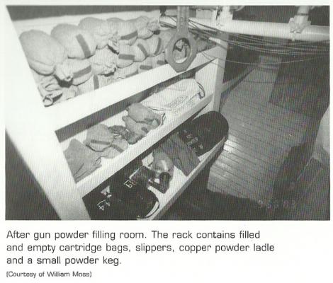
Here is a photograph of the shelf in the aft filling room. It is probably taller than the one in the forward room because there should be more head room. Notice the bags and other items listed. There are still some discrepancies since other pictures I have seen of the aft filling room show copper plates on the floor. Here it shows bare planking which appear to slope up to the right (hull shape?). Also I see sprinkler pipes that are very low. At any rate, I doubt that this shelf was brought here just for this picture.
- 572 replies
-
- 5
-
-
- constitution
- frigate
- (and 1 more)
-
The picture was provided by JSGerson who found it at the following site: http://www.asailorslifeforme.org/educator/scene_magazine-in-battle.php This seems to correlate with the photos sent to me by Henry (Popeye2sea), the local expert in Boston. http://www.asailorslifeforme.org/educator/scene_magazine-in-battle.php
- 572 replies
-
- 4
-
-
- constitution
- frigate
- (and 1 more)
-
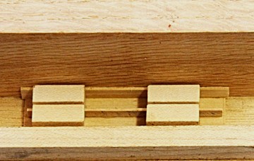
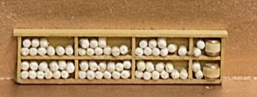
So here we go with the next increment of this cross section (which will take a long time to complete). Gun powder cartridges: The lowest usable section of this parts of this ship will be the gun powder room, water tanks and other storage areas. Earlier I mentioned the confusion about the powder room in the forward section and how it relied on the various modifications of the ship. The part that struck my fancy was the last revision that made the powder room(s) way down deep below the orlop deck, and a drawing provided by Jonathan is what I will go by. I have made book shelves in the past, but never this small. I started with some 1/32 inch thick boxwood for the back, shelves and sides. Then I cut some blocks for the spacers and coated them with wax. The following pictures show how I assembled the storage shelves for the gun powder cartridges and two small powder kegs. When assembled, the room will be lined with copper sheets.


- 572 replies
-
- 11
-
-
- constitution
- frigate
- (and 1 more)
-
I bought some disposable cotton brushes that work quite well. They are made in Japan from compacted cotton. The tips are nice and sharp and stay that way with the paint I used on a couple tiny gunpowder barrels. They come in a pack of fifty with tips at both ends. I got mine at Hobbyworld for a couple dollars.

-
- 4
-
-
To come back to the original question about modeling the James Caird ship, I would recommend to contact the following: http://www.jamescairdsociety.com/ If there is a model kit, I am sure they would know about it. If not, ask for plans and scratch build. The history is great and deserves attention. A ship model would be appreciated.
-
Since fingernail polish remover is acetone, how many women do you know who have had problems breathing the stuff?
-
Turning a Lathe into a table saw
Modeler12 replied to lehmann's topic in Modeling tools and Workshop Equipment
Great job, Bruce. I have an old Shopsmith that I used as a table saw for many years. Then I added a table on top of the 'table' (pun intended), and mounted a four inch blade, etc, etc. It works for me. I also like your usage of the malimine (sp?) board. I have it on my workbench and several other places where I need a smooth, flat surface. What is involved in changing from the lathe back to the saw and visa versa? -
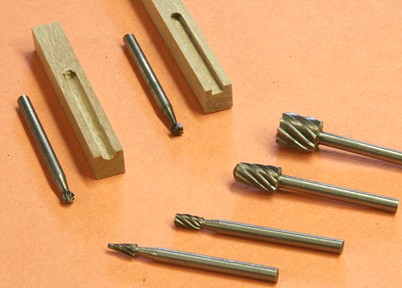
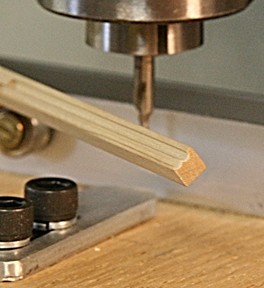
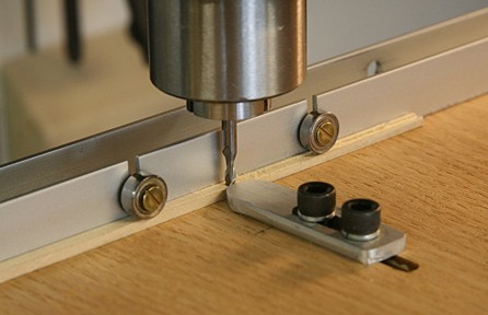
About ten days ago I ordered a set of six bits from Ebay. The price was under $3 plus around a dollar for shipping. I used Paypall to pay. Yesterday I received them in the mail from China. They were made in a small town about 150 miles southwest of Shanghai. I tried a couple on my mill and the results are shown below. They all have a 1/8 inch diameter shaft. I ran them at about 5000 rpm but for the smaller sizes it might have been better to use a higher speed. Notice one is actually a dove tail. At any rate, for less than $4 for six bits I cannot complain and I may order a few more of different shapes.
-
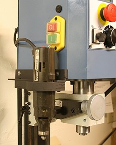
Frank, I should have explained that some time ago I added a clamping fixture to the side of my mill to hold the dremmel like tool. Perhaps the picture below makes that clear. The mill has two ways to move the z axis. There is a long screw in the back that raises the whole head up or down while the blue section can be moved with the quill and knob shown in front. I can also use the lever barely shown to the far right. The quill has two worm gears. One attaches the 'drill press lever' to the quill to move it up and down by hand. The second one activates the calibrated knob in front. There is a button (barely visible on the black tapered part) that engages this worm gear for fine z tuning. The four jaw chuck you see is still mounted on the mill bed (via the tilting and rotary tables). So the router bit is mounted on the mill bed and the Monkeyward's tool does the grinding.

-
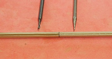
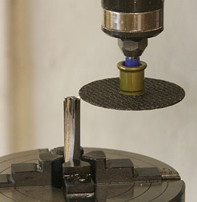
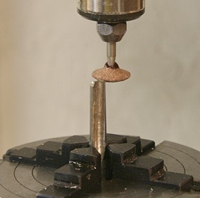
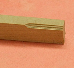
I have always wondered about making my own milling bits to the shape I want. This is my first attempt to do that. I took an old 1/4 inch router bit, mounted it in my rotary table and used the old 'Monkey-Ward's' (Dremmel like) motor with a grinding stone (cut-off wheel or shaped disk). Safety glasses!! I then moved the mill to the area on the bit that I wanted to remove. Here I get confused all the time because of the 'image' problem. Meaning that what you remove is not what the final routed shape looks like. How do I describe this? I had to do this on both sides of the bit by turning the rotary table 180 degrees. I also had to be careful of the angle the grinding wheel makes with the leading edge of the bit (clearance for the cutting edge). My first tries were very gentle and nothing too exciting, but I proved to myself that this works. It is safe as long as I take small bites for the grinding process. Note this is not like holding the dremmel tool with bit to do this by hand. I never liked that idea. I have made scrapers out of saw blades, but even then mounted the old piece in the lathe toolpost and the grinder in the chuck. I tried the minute grooved router bit on a piece of boxwood and the results are below. Now I am ready to try a much larger shape. BTW Don't try this on a bit that has a carbide insert. All it does is grind the grinder!
-
Walnut and basswood would not be my choice when it comes to carving small items like cleats. The grain is too large for walnut and basswood tends to create fuzz and soft spots. The shape of cleats includes a small base to anchor it to the yard (or where ever) and it is this part that splits off easily with large grain wood. Drilling holes makes this problem even worse. I would really suggest you get some boxwood, holly or pear wood. They are marvelous when it comes to machining or carving. I have used pear for tiny parts, stained them and coated them with wipe-on poly, and they came out very nice and even looking.
-
Microlux=Proxxon?
Modeler12 replied to Ulises Victoria's topic in Modeling tools and Workshop Equipment
As Mark mentioned, there may be similarities, but most features in all the equipment are different. To the best of my knowledge, the milling machines and lathes sold by Micro Mark are made in China, and almost the same units are sold by Harbor Freight and others. Proxxon is a German company with sales offices around the world, but their equipment such as the mill and lathes are quite different. Perhaps you were thinking of Proxxon's Micromot line of tools. -
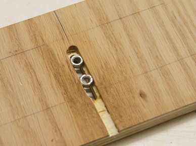
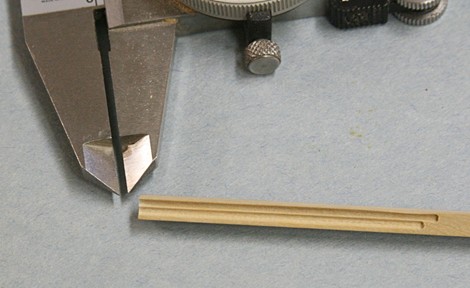
I like this router table. A bit of experimenting with cutters yielded this one. A 1/8 inch center drill has the tip diameter of 1/16 inch almost round. I used it on a piece of 5/32 inch boxwood and cut two grooves right next to each other. The calipers in the picture is set at .062 inches, the width of the grooves. This could be used to make decorative fluted columns, for example. I would need to include two stops.
-
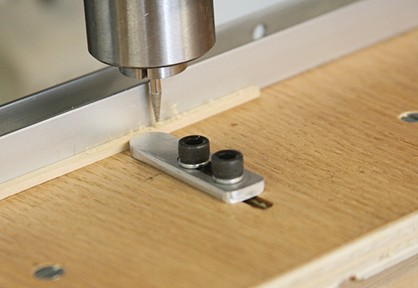
Yes, Frank, I am familiar with these nuts and have used them in the past (although the ones I have are 1/4-20). Meanwhile I have added a couple ball bearings on the fence. Using the same piece of wood as before (1/8 x 5/32 basswood), I routed it and it was very easy to push through with no chatter or up and down variations. There is a small nut on the back side of each bearing to hold it in the slot. I am limited to about 3/8 inch vertical but for any wood that thick, I don't think I have worry about using the hold down feature. In the picture you can also see the slot in the table as well as in the metal guide. That way I can move the whole thing back and forth about 3/4 inch. It goes to show that there are different ways of doing things like that.
-
9-11 how can any one forget this one?
-
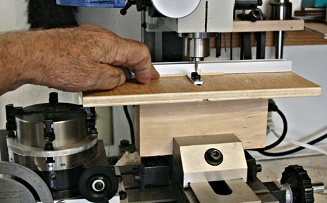
Frank, I liked your idea for the router table enough to jump in and make me one. I adapted it to my mill where I try to keep the 4 inch vise and rotary table mounted on the bed as much as possible. For that reason I raised my router table on a block of wood which can then be clamped in the vise. I wasn't sure how you hold your guide with the two cap screws, but in my case I routed a slot underneath just wide enough for two hex nuts to slide back and forth. The brown spots you see in the picture is some paste wax. This allows me to route planks from zero to 3/4 inch wide. Anything wider can be done without the guide. I have not yet cut the fence for cutter clearance and will wait until I get some cutters. Meanwhile I tried to route a piece of basswood (1/8 x 5/32 inch) using a 1/16 inch diameter end mill and another diamond coated bit. Going with the grain helps to reduce burning, but when I stopped too long there was some darkening of the wood. The edges of both cuts were a bit fuzzy. And I need to do some fine tuning. For sure, I want to add a feather board to hold the work piece down (maybe one on each side). The sample was too flexible and had a tendency to lift up. I want to thank you, Frank, for sharing this nice idea. One more comment about the 'fuzzy edge' etc. When I looked at the slot cut by the end-mill, I noticed there was a visible difference between the two edges. The one towards the picture was sharp and very thin and clear. The other side was not so. The direction of the router bit rotation (and work-piece movement) have a lot to do with this. Climb cutting gives a smoother edge because the wood is sheared and the chips pulled around and away. Perhaps the picture below explains it better: