

Tigersteve
-
Posts
1,314 -
Joined
-
Last visited
Reputation Activity
-

 Tigersteve reacted to Chuck in Sloop Speedwell 1752 by Chuck - Ketch Rigged Sloop - POF - prototype build
Work continues on the forecastle area. With those first two beams in position I can now start working on the bulkhead that sits against them.
In this first picture, I am just test fitting the three sections of laser cut bulkhead. These (like all others) are laser cut slightly wider and taller than needed.
First...work on getting a nice fit on the center section between the riding bits. Only worry about the width on both sides...dont worry about the height of these yet. The two pieces on either side are next...sand the outboard side ONLY to reduce the width and get a tight fit against the riding bitts. There will be a space between the frames and the bulkhead where the inboard planking would have been. Try and make it a consistent width. Again dont worry about the height.
Only after you get the widths taken care of should you then sand the top of each bulkhead section down so the height is flush with the top of the lower beam. The photo shows the three sections with a proper fit all around...now its time to detail them.
Remove the three sections so you can add the uprights and simulated deck beam. First up...sand the char from the laser cut beam pieces. These are glued to the top edge of each bulkhead flush. They are laser cut longer than needed so you can sand the sides flush as well.
Then the uprights go in position. These are the uprights for the cabins on the lower platform. We will be adding them a little later. But it is easier to add these now. They are just 1/8" x 1/8" strips cut to length and glued in place. There are laser etched lines that show you exactly where they should go.
Then glue the three sections in position permanently on the model. Note the riding bitts will not be glued on permanently yet. They will just get in the way when we are doing so many other things in this chapter. So make sure you can remove it after the three sections are glued in place.
Riding bitts removed.
Now for the next layer above that. this is handled in the exact same way. I could have just included these on the first three section only a bit taller, but I wanted to be able to paint them cleanly and get a crisp edge. But the same principle applies here. Sand the widths of each first....then get the heights done. These are flush with the top of the fcastle deck beam. Then remove them.....
Paint them red. Then add the laser cut and etched molding along the top edge. The molding was rounded off on top and bottom. You could also scrape your own if you want to.
Then sit this on top of the lower sections of bulkhead as shown below. The riding bitts are still removable but you must use them to get a good fit. Glue these bulkhead sections in position now as well.
Top this off with the margin plank along the beam. Cut a 1/4" x 3/64" strip for this. Basically, just like you added for the quarter deck margin plank. It hangs over the bulkhead a little bit. The aft edge hanging over is rounded off a bit to your liking. The forward side will leave a nice ledge or rabbet for the fcastle deck planking.
The only difference here is that you must notch out this plank for the riding bitts.
see below. Also the riding bitts are not yet glued in position...I will let you know when its best to glue that in position. BUT I did finally glue the fire hearth in place permanently. Just remember to do so without its stack. That will just break off later without a doubt. And if you want to add anything else to the galley...do it now. We are about to close her up for good with deck beams and knees, etc.
The three fcastle deck beams were cut to length and are just resting on the deck clamps. I must locate their exact positions using the plans.
Thats it for now...BUT I did get a chance to cut the plan sheet up to see how my planking design will look. Its always tricky deciding how much planking to add or leave off the model. I think I am liking this particular cut-away with some planking removed. You can still see quite a bit of stuff down there...
The hearth stack was just placed on top for giggles and a test.
I also did the same for the quarter deck...once again plenty of detail is still viewable down there. I will live with these templates for a while and mull over some other possible planking schemes. But so far I think these will do just nicely. What do you think?
-
 Tigersteve got a reaction from archjofo in HM Cutter Cheerful 1806 by Erik W - 1:48 scale
It’s perfect!
Steve
-
 Tigersteve got a reaction from Ryland Craze in HM Cutter Cheerful 1806 by Erik W - 1:48 scale
It’s perfect!
Steve
-
 Tigersteve got a reaction from mtaylor in HM Cutter Cheerful 1806 by Erik W - 1:48 scale
It’s perfect!
Steve
-
 Tigersteve got a reaction from Canute in HM Cutter Cheerful 1806 by Erik W - 1:48 scale
It’s perfect!
Steve
-
Tigersteve reacted to Erik W in HM Cutter Cheerful 1806 by Erik W - 1:48 scale
One last photo for the week. I drilled the interior scupper holes. This was a bit nerve wracking. I hadn't anticipated how easy it would be for the 1/32" x 1/32" waterway strip to split while being drilled. I wound up starting with a much smaller drill bit and then using three more progressively larger sizes to only take a slight bit of material off at a time. I made sure to turn the pin vice really slowly. If the waterway split, the split part was still attached at one end. I took a sharpened toothpick, applied a tiny amount of wood glue, and glued the fragmented sliver back down. I had to do that with three of the holes. The splits are invisible. Glad I'm done with that part!
Also, I'm not sure of the properties of wood in general, but I'm curious if my boxwood, which I've had for 9 years in an inside climate that has a humidity of around 25% most of the year, splits easier because of that.
Erik
-
Tigersteve reacted to Erik W in HM Cutter Cheerful 1806 by Erik W - 1:48 scale
This week I decided to mix things up a bit, taking a break between making the backstay plates and the chain plates. I made the 22 eye bolts for the hull exterior and cap rail top. While I have every manner of small diameter wire - lead, brass, copper, phosphor bronze, steel - down to .002" diameter, I didn't have the type of wire best used by ship modelers for these types of things. So after some research on this forum I ordered both 24 and 22 gauge Hillman Group dark annealed wire. I must say, trying to make 22 identical eye bolts was more of a challenge than I thought it would be! I never did get to a point where they were consistent. That said, I selected groups that were close to identical to one another to fasten in the same area. I figure if the port side eye bolts are slightly different than the starboard, a viewer would never know since you only see one side of the ship at a time. I followed what Mike (Stuntflyer) had done in his Cheerful build log, and filed a little channel around the holes so the eye bolts snug down a bit.
I also drilled the scupper holes in the outside of the hull. This was pretty straight forward, other than when I went to photograph the model I could see the bright wood on the inside of the bulwark. I wound up taking a fine brush and painting the interior black, followed by running a pencil around the plank edge of the hole.
My next step will be to drill the scupper holes on the interior bulwark/deck area. Does anyone have any advice or wisdom on that? Am I drilling all the way through the interior planking? I know I need to make the holes so they notch into the lip of the waterway at deck level.
Erik
-
Tigersteve reacted to Erik W in HM Cutter Cheerful 1806 by Erik W - 1:48 scale
A little bit of progress this week. I'm new at metal working, so it took some trial and error to figure out how I am going to make the backstay plates and chain plates. One of the main issues to getting the ball rolling was figuring out how I was going to make these without the availability of 1/64" x 3/32" brass strip. It would appear that K & S has discontinued nearly its entire line of brass strip, and I couldn't locate any of the size I needed in my internet search. Many years ago I had bought a package of various sizes of 6" x 12" brass shim stock (used to shim the plates when molding parts in plastic injection molding machines so that they align correctly) just in case I ever needed sheet brass. These sheets came in thickness of .001", .0015", .002", .003", .004", .005", .006", .007", .008", .010", .012", and .015". The .015" thickness is the decimal measurement of 1/64". So I have my material. I used a pair of ancient tin snips I have in my toolbox to cut 3/32" wide strips off the sheet. I then had to flatten the strips since they curled both along the face and the edge. Next I filed the sharp edges flat. Then used flat pliers to eliminate the lengthwise cupping caused in cutting the strips off the sheet. Now that I had my self-made strips ready, I then shaped the backstay plates following Chuck's instructions in his monograph. Since the strips I created were rough and with blemishes, I polished the finished backstay plates with a fine file after shaping was complete, just because I'm a perfectionist, and that's how I roll! Yes, I know they'll be painted black. Haha.
Erik
-
Tigersteve reacted to Erik W in HM Cutter Cheerful 1806 by Erik W - 1:48 scale
Not a ton of progress this week. I did finish fashioning and installing the boarding ladders and channels though. I must say ripping the boards by hand out of sheet stock to make these parts is a bit of a pain in the rear. lol. Also, it was tough getting the pattern cut into the scraper to make the boarding ladder profile. I think my limitation there was my lack of precise small files. I deliberately made the filed notches in the channels that will house the chainplates narrower than they'll be. I just wanted to get the notches placed correctly and the angles in, according to the plans. I'll finish the notches up when I fit and attach the chainplates.
And lastly, I'm patting myself on the back. My third photo below manages to capture the elusive and hard to photograph lower step of the Cheerful's boarding ladder (located on the wale and painted black). Haha!
Erik
-
Tigersteve reacted to Tom E in US Brig Niagara by Tom E - Model Shipways - 1:64 Scale
Evening,
Hope everyone is well and warm.
It's been a cold snowy and icy week of work. Too exhausted to build, but I think an update will suffice.
With the fore lower shrouds in place and the sheer poles installed.
I wanted to get the Tye and Halliard for the topsail yard rigged in before moving onto the rest of the shrouds.
My thinking, it will be easier to do first, before setting in the topmast and topgallant stays.
In the end it was all fiddly but was more difficult in my head.
The set up will be fully installed on the pin rail with a rope coil done later.
What you do to one side, you do to the other.
Ship building at its simplest.
With things falling into place, I could move onto the topmast backstays.
Just worked my way down that side of the ship.
I would alternate when installing shrouds. Set two on one side, then the other.
I never favored one side, finished it, then do the other side.
Tried to be as symmetrical as I could.
The topgallant backstays could then be set in.
Once both sides where completed, it put a fair amount of tension into the rigging running to the bowsprit.
This was by design.
The royal backstay will be installed next.
Be good,
Tom E
-
Tigersteve reacted to Chuck in Sloop Speedwell 1752 by Chuck - Ketch Rigged Sloop - POF - prototype build
Thanks Mike. I am working on it a lot lately. Mostly because I lack the wood to make many parts that are now out of stock. So as I get more I will be busy with inventory. So while I wait...
I managed to get the transom beam in position. Much like the Winchelsea, it was made in layers to simplify it. These are all laser cut. But slightly longer than needed just in case. They were pre-bent in a jig set up. This is crucial. I used some scrap 3/16 x 3/16 wood under the center to bend it. I just clamped the end and then blasted it with the hair dryer on super hot. Note the wood scraps on the ends too. This protects the ends from denting and other damage. All of the layers are done like this. Using the 3/16" x 3/16 strip makes the perfect bend we need..
Testing it in place. Layer one. Not glued in yet. but pretty tight.
Then repeat with layer two on top. No need to bevel the back edge. Just slide it against the stern frames. Then glue the top layer onto the bottom one while on the model. I found that helpful. You will be able to remove the whole thing because the bottom layer isnt glued in. This way you can sand it a bit if needed and clean it up.
Testing the transom beam with the other six. They should be the same height and a test with a strip of wood confirms this. The deck planking will lay nicely on top.
To finish off the transom beam, you can glue the final 3/64" thick layer on the top. This one will show so take your time cleaning it up. The back side was beveled to sit flash against the stern frames. The same was done on each end against the bulwarks so I got a tight fit. One of the red arrows shows this top layer. Note that it is narrower and leaves a nice rabbet on the forward side to accept the qdeck planking.
The other red arrow shows a laser cut filler on the 3/64" thick. This is glued to the bulwarks and will be important in the next step.
And finally...the iron straps are added. These are laser cut on black laser board. Each iron strap is in two pieces. One on the beam and the other curved section on the deck clamp. These will hardly be seen. In fact I think they are mostly covered later...what a pity.
Next up was the planked inboard side of the transom. This is laser cut in one piece with etched lines to show the planking. Just bevel the sides for a tight fit. Also bevel the bottom edge as well. This was actually pre-bent in that same jig set up to establish the curve. It worked great. Use the 3/16" x 3/16" strip in the center like before. Once I got a tight fit I removed it and painted it red before gluing it in permanently. This helps me keep a crisp edge on the bottom with no sloppy paintwork. Then glue it in...
The top of this area was prepared next. It is laser cut in a way that the grain makes it super easy to bend. So no jigs are needed. In fact be careful as it is delicate. The top is done in two halves. I have given folks and extra set just in case. There are notched for the stern frames. They are laser cut smaller than needed so you will need to enlarge them to fit tightly around the stern frames. The back edge was also beveled so it fit nice and tight.
Then repeat with the other side. Note how the top is flush or nearly flush with the cap rail.
Then a front mold piece finished it all up. Sanded to fit tightly and all prepared for painting. It is also 3/64" thick.
Then its all painted and cleaned up...once the paint work is tidied up, this really finishes off the inboard side of the transom well.
Next up I remove those six qdeck beams once again and start work on the locker benches and rudder trunk.
-
Tigersteve reacted to Erik W in HM Cutter Cheerful 1806 by Erik W - 1:48 scale
Pop the champagne, I'm finished with the deck planking! While a challenging and rewarding experience, I'm happy to be finished with planking. Like everything else with this build, planking the deck didn't quite go as planned, even with the tick marks and planks drawn out beforehand. And as you other perfectionists out there can sympathize with, there are a bunch of things that didn't turn out the way I would have liked. That said, I'm happy with the results, and the quality of the deck planking is in line with the rest of the build. Which is all I can really ask for as someone being new to this wooden ship building thing.
After thoroughly cleaning my hobby area of sawdust, which is also my home office, I'm happy to be moving on to less dusty parts of the build! I plan on starting Chuck's mini-kit of the windlass this weekend.
Erik
-
Tigersteve reacted to Chuck in Sloop Speedwell 1752 by Chuck - Ketch Rigged Sloop - POF - prototype build
I finished up the aft platforms...
They were both planked with the scuttle lids being finished as described earlier. But then two upright timbers were cut to length (3/16 x 3/16) and placed on both sides of the open hatchway. This gives it more support so you can Carefully cut away the beam between them. It will look like the pic below when done.
Then you can make the short ladder that goes in that opening between platforms. This is typical and laser cut for you. The only difference is that this ladder is tilted or skewed sideways. Its an interesting detail. The reason for this will become clear when we start building out all of the cabins. There is a small square with the angle you will need for this ladder on the plans. See below.
This is what it looks like in position. Brutal close-ups...
Then I figured it would be fun to build and install the shot lockers.
All pieces are laser cut. The sides were glued on top of the back piece first. They were placed at right angles neatly.
Then the front is added...which is shorter and has laser etched plank details.
Next comes the top piece. This was laser cut a bit wider than needed for wiggle room. It was glued on top and then the back side was sanded flush where the top hung over the edge. The lids were also prepared. It is one piece with some laser etched details. Basically you have to bevel the top and bottom edges. Quite a bit as you can see.
Here the lid piece was added. It has etched reference marks for the hinges. The hinges are laser board and added the same way we did them for the fire hearth. The top and bottom halves of the hinge are separate pieces. They are glued on first. Then to finish them up a small length of 24 gauge black wire was used to simulate the hinge pins between them.
And finally added to the model...you may have to adjust the height of the shot locker AS you are building it. It all depends on whether or not you placed the height of the aft platform differently. Maybe you placed the platform lower and thus your shot locker may have to be shorter. Measure twice and cut once sort of thing...its so important to get the platform heights correct. But if you didnt, thats OK...just do some problem solving and with some adjustments you will be just fine. I would even go as far to suggest that you test the back piece in position before you assemble the shot locker. Then you will know if its too tall or short and you can adjust accordingly.
-
Tigersteve reacted to Erik W in HM Cutter Cheerful 1806 by Erik W - 1:48 scale
Thanks for the likes and the encouraging comments. I finished more of the deck planking this week. I did my first scarph joints on the deck. The remaining planking will be more time consuming since it involves cutting the planks out of wood sheet. One note on planking color. Since I have 2 different batches of 3/16" wide wood for the main planking I used, which are both different from 7/32" wide planking I used, which is different again from the wood sheet, I decided to deliberately mix up the planks of different shades from the beginning. The plank color would vary anyway, and this kept it varied throughout the deck, rather than having bands of different shades as I transitioned from the planking stock to sheet stock. The photos were taken after a quick first sanding.
Erik
-
Tigersteve got a reaction from Canute in HM Cutter Cheerful 1806 by Erik W - 1:48 scale
Keep up the momentum. It’s looking great Erik.
Steve
-
Tigersteve got a reaction from Canute in HM Cutter Cheerful 1806 by Erik W - 1:48 scale
Looks really good.
Steve
-
Tigersteve got a reaction from Canute in HM Cutter Cheerful 1806 by Erik W - 1:48 scale
Welcome back! I doubt anyone has forgotten your build of this. I was wondering when you would return. Lol
Steve
-
Tigersteve reacted to Chuck in Sloop Speedwell 1752 by Chuck - Ketch Rigged Sloop - POF - prototype build
Step by Step...
1. Laser cut cedar brickwork. Lightly sand the char. But not so much that you remove the etched mortar lines. Just a little. Especially on the edges of the pieces. Many have bricks etched on both sides.
apply wipe on poly when finished...this is important to seal the wood a bit.
2. Yes its bright!! But this is just the initial steps. I used a red promarker, you can see which color to add the base coat of red to all faces of the brickwork. Also note the two pieces that make up the sides have been glued together. Make sure you have the holes and pieces facing the correct direction.
3. Glue the sides to the back wall. Keep nice right angles. Also add the front piece. This is left a bit long and you will have to trim it to fit. DO NOT glue to the base. This will be done much later in the project. Much, much later.
4. Using weathering powder add some red/brown colors and dark browns to suit. It depends on how weathered you want to go with the fire hearth. You will see this at the end. Spray all the pieces lightly with some matte spray fixative when you are done.
5. This is where the magic happens. You could use white weathering powder but that would also pigment the bricks. You dont really want that. So instead use regular white flour. Brush it on and push it into the mortar lines which are made pretty deep for you. Dont go for a perfect even coverage here. Experiment a little. Push it in the cracks with your finger....pack it in there. Then brush it off the brick faces with a light touch. Experiment for the look you really want...use some additional weathering powders if you want to add soot and ash. Make it a used hearth or a relatively new one!!! Also note the frame on the base was painted black. Dont spray with fixative. The normal humidity in the air will fix the flour in position on its own. It may take a day or so depending on the weather.
6. 1/32" brass wire/rod (not included) were blackened and added as shown above.
7. The hood...laser cut from 1/64" thick boxwood. Glue the shorter back piece on the base first. It should be a at a perfect right angle vertically and centered.
8. Add the two sides. You will need to bevel the bottom to sit flush on the base.
9. Add the front piece...which is taller than the back piece. Note how the front hangs over the the front of the base just a bit. That is done on purpose. It is correct.
10. Finally add the top and front pieces. apply filler to all the cracks and sand smooth for painting. Also build the stack the same way and prepare for painting.
11. Hinges are laser board. Construct them in the sequence shown above...left to right. First add the bottom half of all the hinges. Then the hinge pins are glued along the top edge. Use 24 gauge black wire for that. To finish that up, set the top half of the hinges above the wire. An eyebolt is also added in the center. You can see that in the photos below of the finished fire hearth. There are two of them shown...
A beat up used and weathered fire hearth....and a shiny almost new hearth. Have fun with it and weather to your preferred tastes. LOL
NOTE....the hearth is NOT glued to the base yet. And the stack is NOT glued to the hood yet. It is best to keep them separate for now.
-
Tigersteve reacted to Chuck in Sloop Speedwell 1752 by Chuck - Ketch Rigged Sloop - POF - prototype build
Finishing up the platforms with the ringbolts for the scuttle lids. I also made a quick mock-up today of the fire hearth. Unlike the Seawatch books I am deviating from the traditional stove. I have built a lot of traditional iron stoves in my time. Based on the original drafts and on the draft for the similar sloop Fly I am going with a brick fire hearth. The contemporary draft is shown in the photos below. You can clearly see the bricked up hearth. I think it is a much more interesting fixture and its something I have never modelled before. You guys can go either way...its up to you. But I will only be making a mini kit for the fire hearth for the model. This was actually very typical for sloops of this time period and I found a great deal of source info for these.
All of the brickwork is lasercut cedar. The hood parts are thin boxwood sheet with laserboard hinges. I will of course have to make another because I didnt take step by step photos. I used a really easy and neat technique to weather those bricks. I will detail that when the time comes.
The fire hearth isnt permanently added yet. I will however glue the base onto the platform at this time.
-
Tigersteve reacted to Erik W in HM Cutter Cheerful 1806 by Erik W - 1:48 scale
It's been a couple of weeks since my last post. I'm taking my time planking the deck. Like everything on this build, it's more complicated and challenging than I had initially thought it would be. Haha. I've managed to get eight more rows of planks down since my last post. I only did a rough sanding, which is why it still looks a bit crude. I'll do a final sanding once the entire deck is planked. Even though I have tick marks on the deck and the planks drawn in, it still takes some effort to get the planks a uniform width, and the run of each plank to flow smoothly when viewed down the length of the hull. At any rate, for a first deck planking job, I'm happy with the results so far.
Erik
-
Tigersteve reacted to Chuck in Sloop Speedwell 1752 by Chuck - Ketch Rigged Sloop - POF - prototype build
Before I can begin placing the beams for the lower platforms, I must make a height gauge first. There are many ways to do this and a system will be very important to have moving forward on this project. Greg describes one method in his books on Speedwell. I have decided to go another way. I prefer to make a depth gauge of sorts.
Here is a photo...you folks can of course select any method you prefer. I am fond of this one and such a gauge can be made with readily available scrap strips...Note how the pointer is a separate it to be slipped onto the lower shaft. It is basically a very large T-square. I used 3/32" thick strips but they are fairly wide so they wont bend or flex. The center of the "T" is thinner at about 1/16" thick.
The pointer is meant to be slid onto the center shaft of the "T". Everything is squared up and at perfect right angles. Nice and neat.
Basically take the measurements from the plans to find the depth of any beams etc. Like the forward platform beams. The underside of the "T" is set flush with the sheer on the plan. Then I mark the top of the platform beam on the center shaft...without the pointer on it. Just a pencil tick mark.
Then the pionter is added to the shaft and lined up with the tick mark. The pointer must fit nice and snug so it doesnt shift around. Its a very tight fit on purpose. Then the depth gauge can be brought to the model as shown. Repeat on both sides for each beam end. I am marking the height for the tops of the beams. Find where that beam should be and mark its height on the model. Repeat this process for every lower platform beam end. Then connect the marks to find the proper height for the platform. Basically repeat this on both sides. Hope that makes sense.
I am basically trusting that my sheer on the model is correct and even on both sides. I am confident...
But if your sheer is off you have bigger problems anyway. No matter what method you choose there will be issues. This is just one method that can be used. I did this for all the lower platform beams which are 3/16" x 3/16" cedar. That is except for the most forward platform which has 1/4" x 3/16 beams just under the stove. Check you plans carefully. The beams have no roundup and are just cut from strip stock. They are carefully measured and shaped to fit snug. Placement is important here.
In fact the placement of the first 1/4" x 3/16 beam of the forward-most platform is very important. It is exactly 5/16" away from the beam aft of it on the lowest platform. So a small jig was laser cut to help find its location. This will be provided. It sits on the lower platform beams which went in first. It has laser etched marks to help you place that first beam in position correctly at the right height and the right distance from the lower platform beam.
Once all seven of the forward platform beams were in place I tested my placement with the a cutout of the plans. Everything is level and the plans fits pretty darned good.
Next up is to add the a bulkhead and some additional framing on these platforms before I plank them.
Hope this makes sense...
Chuck
-
Tigersteve reacted to svein erik in US Brig Syren by svein erik - Model Shipways - 1:64 - 18 gun brig
Hi, oki, its bean some wile since i worked on the syren, maby i will finished it in 2024? 😉
am trying to get all of the bits and peaces glued on and make up all the masts etc so i can
startthe rigging , so i have some hope this year😉
svein.e.
-
Tigersteve reacted to Erik W in HM Cutter Cheerful 1806 by Erik W - 1:48 scale
I thought drawing in the tick marks and drawing the placement of the hook scarph joints wouldn't take too long. Well, after about 12 hours over the last week, I'm finally happy with the way everything looks on the deck, and I'm ready to proceed with the deck planking. Getting the drawn-in planking to look and flow the way I wanted it took so many adjustments and needed to be redone so many times I actually had to go out and buy more erasers! The last redo was actually after these photos were taken. I moved the rear of the aft scarph joints back a bit after viewing the photos, in order to have the taper of the outer 4 planks better match the inner 6 planks aft of the skylight. I also tweaked a couple of other areas after viewing these photos. Since I've never planked a deck before, my goal was to spend as much time as necessary to get the planking drawn in on the deck. Sort of the planking version of adding training wheels to a kids bike, or having bumpers in the gutters when kids bowl at a bowling alley. I'm trying to minimize my chances of screwing the deck planking up since it will be a very visible part of the build. The saying, proper planning prevents poor performance, comes to mind. One note when looking at the photos - since the plank lines were drawn in straight lines between the tick marks, it doesn't flow as smoothly visually as the actual curved planks will.
Erik
-
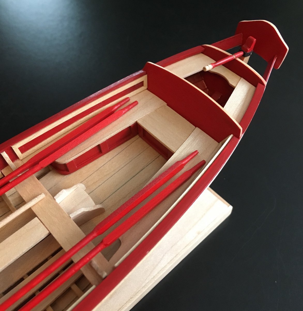
 Tigersteve got a reaction from KennyH78 in 18th Century Longboat by KennyH78 - FINISHED - Model Shipways - 1/48 Scale
Congrats!
Steve
-
 Tigersteve got a reaction from Nirvana in 18th Century Longboat by KennyH78 - FINISHED - Model Shipways - 1/48 Scale
Congrats!
Steve