


RFP
-
Posts
49 -
Joined
-
Last visited
Reputation Activity
-

 RFP reacted to jbelwood in Portland by jbelwood and norm1116 - BlueJacket Shipcrafters - abandoned
Finished the Portlands skylight. I started by making a pattern of the rabbeted base on a piece of manila folder.
Decided to have the vertical window framing 1/2" apart. Measured around the perimeter of the pattern and
drew a line every 1/2" and place a blue dot on each for identification.
Here you can more readily see the idea. At this point I painted the window wall with Floquil Engine Black. When dry,
I burnished it with a soft cloth which produced a nice sheen.
Fastened the pattern to the base with double sided tape and added the frame work. Used 1/32" x 1/16" bass wood strip along the base
and uprights. Used 1/32" square where the window wall meets under the roof.
Painted the roof Floquil CN Gray with a white stripe around the edge. Not glued down yet but here it is finished.
John Elwood
Stratford, CT
-
 RFP got a reaction from etubino in Portland by jbelwood and norm1116 - BlueJacket Shipcrafters - abandoned
John, you're awesome!
-
RFP got a reaction from etubino in Portland by jbelwood and norm1116 - BlueJacket Shipcrafters - abandoned
I've got a question about the paddle wheel and it's 'box.' There is a lot of 'headroom' at the top of the wheel... what is all this space for? In the real world, does the wheel move up and down (like the wheels/tires of a car) and the space is needed for that travel. I know my question has nothing whatsoever to do with the build log, but I'm wondering...
Rob
-
 RFP got a reaction from norm1116 in Portland by jbelwood and norm1116 - BlueJacket Shipcrafters - abandoned
John, you're awesome!
-
RFP reacted to jbelwood in Portland by jbelwood and norm1116 - BlueJacket Shipcrafters - abandoned
Just thought I'd throw this photo in for something different. Perhaps the most
photographed scene on my layout.
John Elwood
-
RFP reacted to jbelwood in Portland by jbelwood and norm1116 - BlueJacket Shipcrafters - abandoned
Hi there Norm,
Thanks for all those photos. I've heard many very positive comments about the museum from fellow modelers
who have visited there. From your many photos, I can see why.
I have yet to get back to the Portland. My overall health has slipped to a point where the passion to build has
diminished considerably. I did finish the trestle however.
Although it doesn't show, there are 374 pieces in this model, all cut from sprues. I estimate 70+ hours of work. It is to
be installed on a friends Northern Pacific layout over Elwood Gulch. You couldn't pay me to build another one.
John Elwood
-
RFP reacted to norm1116 in Portland by jbelwood and norm1116 - BlueJacket Shipcrafters - abandoned
John,
Take care of yourself, and get well. That trestle looks spectacular!
In a million years, I might be able to produce a model half as good as what you have produced. Your train stuff is unbelievable. I wish I had the skill you show in your work!
-
 RFP got a reaction from Nikiforos in Santa Lucia by AntonyUK - FINISHED - Panart - 1:30 scale - Sicillian Cargo Boat
Thanks for the update. I've been really looking forward to this build. I am fascinated with these little 'working boats' and know that your build will be very instructive to a newbie like me. As soon as i tidy up about a g'zillion other (non-model) projects, I am going to build this beauty. Again, thanks for such thorough posts.
Rob
-
RFP reacted to norm1116 in Portland by jbelwood and norm1116 - BlueJacket Shipcrafters - abandoned
Priming, Hull Paint, Waterline, Keel, Stem Post, Stern Post
I learned a lot about painting. Actually I remembered most of it from the past, but it came rushing back while painting the hull.
I suck at painting.
Spray, brush, you name it, I am no good at it. So here goes...
I felt that I did an OK job getting the hull ready to paint. I figured after a coat of primer I'd notice a few spots to fix. Let me tell you, painting the hull showed me how wrong I was. My hull has many more imperfections than I would like to admit to. I'm letting many of them go since they will not be visible on display, but they are there!
I did a couple of primer coats using a white spray primer.
You may have noticed that I forgot a step. I need to refer to that manual more often. I should have installed the keel, stem post, and stern post first. To get there, I needed to take care of my display needs.
I purchased the optional stanchions and display board. Both are exceptional. I knew the keel would need to be removed where the stanchions are located. They recommend and send 3 stanchions for the Portland, but I want to try only 2. My thought is I could set it up for 2 and add the third later if needed.
I pulled out the display board and decided how I wanted the boat to sit on it. I drilled holes for the stanchions.
I used my string to find the center of the hull. I set the boat on the stanchions where I wanted it to sit, lining up the center as close as possible. I then pushed a screw up through the stanchion to mark where the hole would need to be drilled in the hull. I drilled that 1 hole on the center line, and mounted it to the base. I aligned the 2nd hole, and marked it with the tip of a screw through the stanchion. I unscrewed the hull, adjusted the 2nd mark to the center line, and drilled the 2nd hole.
I remounted it all to see the results. Check out that display board. It is really top notch.
I'm sorry I didn't take any photos bending the wood around the bow, but I followed the manual and here's what I ended up with. Using the plans, I tried to have this part meet the keel where the thickness changes. I don't remember the exact measurements, but the keel is the same thickness until it approaches the bow, where it thins out a bit.
I knew the keel would need to be cut out for the stanchions, so I added the first piece.
I added the keel between the 2 stanchion holes, and the keel post.
Using a sanding block, I sanded this area so the keel smoothly rounded the bow. I left the bow part thicker than the plans show. I may need to resand it later, but I wanted a bit if insurance just in case. You can see the final product below:
I used calipers to measure where the waterline is on both ends of the boat and marked the hull at those locations.
I needed a flat area to do this work, so I used the kitchen island. I liked John's use of a large mirror, but if you saw me you would understand why there are no large mirrors at my house.
Using my highly professional Norm-O-Matic waterline marker, version 2.0, I lined my pencil to the mark on the bow.
The pencil did not align at the stern.
I added the necessary shim to raise the stern to the correct height.
That did it.
The next step was to make sure the port and starboard heights were the same. I used the square and made necessary adjustments. I went by the deck height. It worked out alright.
I drew the line around the hull. Be careful around the sponsons. It felt tricky.
If I took a photo of both sides of the boat, the waterline looks "off" a bit. But I think it's because of how I built the sponsons. Not really noticeable, but it's there.
I think the first place I heard about Tamiya tape was on Dan's Portland page. Then John mentioned it also. So, I decided to buy some from Amazon. Worth every penny! I don't know how others do the waterline thing, but my thought was to use the tape to cover the line I drew, then mark the line again for cutting. It turns out that the Tamiya tape is kind of see through!
So, using a fresh X-Acto blade, I carefully trimmed the tape at the marked waterline.
I do not have a photo, but I added a 2nd layer of tape below the first so I wouldn't have any slip ups. So here's the first coat of red, hand painted with the paint I got from BlueJacket. Another plug for them. It is really nice paint.
A bit of sanding and a 2nd coat.
More sanding, a third coat, and remove the tape! I have a touch up or two to take care of, but in display mode, I'm accepting my work as it appears.
Thanks as always!
-
RFP reacted to norm1116 in Portland by jbelwood and norm1116 - BlueJacket Shipcrafters - abandoned
I went to Annapolis to visit the Naval Academy Museum. They have quite a collection of models and other items. Some of the models are as old as the original ships. They have a model of a walking beam engine. It is displayed in a position where it is difficult to get a shot of the back of it. Also, it is attached to an electric motor and gear so you can see how it worked. That part was out of commission, but there is a youtube video of it.
Here's a video of the walking beam engine I took. If it doesn't work, message me.
Walking beam video
Here's a few pictures I took while I was there.
-
RFP reacted to norm1116 in Portland by jbelwood and norm1116 - BlueJacket Shipcrafters - abandoned
Here's a kit model for anyone that likes walking beam steam engines - it is 41" tall and over 175 pounds! It could be one heck of a build log!
https://downrivertools.com/marine-beam-engine-castings-and-drawings-set.html
(This link appears to be unavailable as of 07/18/2020. Really cool model though!)
It interests me that the walking beam in the kit photo is red. I noted that Dan painted his red, and the 1996 kit has a brass walking beam with red tinting - see the brass photos in the 1996 kit section.
After reading RFP's post, I went on youtube. If I read it right, there is a video of a working walking beam engine that is being used in an RC paddle wheeler. There is also a video of a walking beam model at the Naval Academy. I'm an hour away from there and will go and get some photos of it. I'm not going to go crazy, but I'd like to represent the engine as best as my skill allows. I may reconsider using the red tinted walking beam from the 1996 kit.
Here's the link for the walking beam engine the builder is using in a RC paddle boat:
RC paddle boat
-
RFP reacted to norm1116 in Portland by jbelwood and norm1116 - BlueJacket Shipcrafters - abandoned
Sponsons
My stepson and I got this far when he started his Portland back in 1996. At the time, the plank on frame instructions did not seem to be the best way to conquer them. I'd like to show what we did back then, then I'll show the 2019 model.
In 1996, we decided to make the sponsons out of solid balsa. It actually worked out!
Having stored the kit for 23 years, one of the sponsons was dented.
Not bad! We only got 2 completed. That was the end of the 1996 build. I considered doing it again on the 2019 kit using basswood this time.
I couldn't remember how we got the shape down so well the first time. After some consideration, I abandoned this method.
I really liked John and Clarence's method described by John in his sponson post. I got everything together successfully, but didn't feel I could hold it in place to glue it down. Then I saw Dan's sponson build. He used 3 frames as a support for a one piece sponson like John's. I went one step further. Probably overkill, but It kept my brain on the right track.
Using 2 sided tape, I taped the back of the plans to a 1/16th basswood sheet and cut out the sponson profiles.
The stern sponson profile for under the deck was too wide. I trimmed it back so the clearance to the deck edge was the same as the plans.
I cut some spare profiles out of old file folders.
The additional step I took was to cut out an additional deck and hull profile out of 1/16" basswood. On the deck profile, I scribed back 3/32" to accommodate for the angle of the one piece sponson. I also cut it off where it will meet the formed rounded tip of the sponson.
I glued that piece down. It's just framing.
I cut out a hull profile and scribed it 5/32", 3/32 for the angle, and another 1/16" for the thickness of the other profile. Again, I cut off the rounded end where I would place the tip of the sponson.
I installed 3 frame pieces.
I shaped the rounded end from the basswood supplied with the kit and glued it in place. John mentioned he cut a rabbet to slip under the one piece sponson. It provides a lot of additional support and was easy to add. Thanks John!
I used John's method to determine the size of the sponson. That worked perfectly. I cut out those parts. I soaked the thin end of the sponson so I could get it against the hull. I CA'd the part into place. The molds were probably overkill, but it really kept me on track.
Once it dried, I started using filler.
I'll sand this out and add more filler as needed. So I'm calling this "1 out of 4 done". I'll add more photos as I move through the filling/sanding, and I'll add a few photos of the remaining 3 sponsons.
I'm sure it's been done successfully, but the plank on frame method does not appear to be the easiest way to go. I'd like to thank John, Clarence, and Dan for getting me where I needed to be on sponsons!
Lots of filling and sanding to do, but here's the 2nd sponson.
I started one of the forward sponsons today. I had made measurements per John's instructions, and cut out 2 sponsons a few weeks back. Both looked good, but I still wanted a bit more support behind them. I went a different way with this one. I glued 1/16" strips on the back of the sponson.
I sanded the edges so the entire thing would sit in place correctly.
I CA'd the first 3 inches, and continued until it was in place. I worked on the bull nose piece.
I have plenty of filling and filing to do, but I'll do that after completing the 4th sponson.
Monday 08/12 I installed the 4th sponson. I will post additional photos after the filling/filing/sanding ritual that is next.
-
RFP reacted to jbelwood in Portland by jbelwood and norm1116 - BlueJacket Shipcrafters - abandoned
Have been away from my computer for the past week. Spent the week visiting my daughter and SIL
in their summer cottage in Digby, Nova Scotia. Photo was taken in November last year. All last week
the Bay of Fundy was extremely calm. Digby is advertised as the World's Scallop Capitol. Bought them
fresh off the boat.
Thin line in my photo of their photo is due to failed pixel sensor.
John Elwood
-
 RFP got a reaction from GrandpaPhil in Portland by jbelwood and norm1116 - BlueJacket Shipcrafters - abandoned
I've got a question about the paddle wheel and it's 'box.' There is a lot of 'headroom' at the top of the wheel... what is all this space for? In the real world, does the wheel move up and down (like the wheels/tires of a car) and the space is needed for that travel. I know my question has nothing whatsoever to do with the build log, but I'm wondering...
Rob
-
 RFP got a reaction from Nunnehi (Don) in Portland by jbelwood and norm1116 - BlueJacket Shipcrafters - abandoned
I agree, Dan, this is a great build log. I am so glad that real craftsmen are working on the Portland now... I'm ordering mine in September, and the work chronicled here will be massively helpful. ;-)
-
 RFP got a reaction from mtaylor in Portland by jbelwood and norm1116 - BlueJacket Shipcrafters - abandoned
I agree, Dan, this is a great build log. I am so glad that real craftsmen are working on the Portland now... I'm ordering mine in September, and the work chronicled here will be massively helpful. ;-)
-
 RFP got a reaction from J11 in Portland by jbelwood and norm1116 - BlueJacket Shipcrafters - abandoned
Wow, John, you're awesome!
-
RFP reacted to jbelwood in Portland by jbelwood and norm1116 - BlueJacket Shipcrafters - abandoned
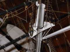
It's been a while since anyone has posted here so I thought I'd bring it back to life.
Putting the paddle wheels together is a bit tricky so here's what I did.
I cut two lengths of wood approximately 7/16" wide and clamped them between the
wheel formers. after spending some time finding three radials where the spokes and
rings coincided. Once that was established I added the paddles with CA being careful
to orient them properly. Take your time here as the paddles are easily broken.
Unfortunately, I couldn't find a way to clean the brass prior to painting. Would suggest
washing the oils off your hands prior to working on this assembly. I finished by spray
painting two coats of Floquil Santa Fe Red onto each wheel.
John Elwood
-
RFP reacted to jbelwood in Portland by jbelwood and norm1116 - BlueJacket Shipcrafters - abandoned
Here is the final finish on the hull. The photos speak for themselves. I forget
what I used for the bottom color. Again, large rattle can.
The last photo gives away a secret. Yes, I am also a model railroader, have been
for more than 40 years. The two on the left display cover articles that I had in
Model Railroader magazine and Railroad Model Craftsman more than a decade
ago. The layout itself has more than twelve feet of maritime scenes.
John Elwood
-
RFP reacted to norm1116 in Portland by jbelwood and norm1116 - BlueJacket Shipcrafters - abandoned
Rob,
Thanks, and I agree! John's info is going to be instrumental in my success, as is the build log Dan Evans recently started.
John,
Great paint shots. I'm working on the deck mock up now. I want to be sure the paddle wheel sub assembly fits in properly, so it will be a few days before I get there. I set the salon decks and took them off as they are not straight. Going to reset them in the next couple of days.
I have just started a part time job with the main goal of getting some exercise through work. The other option was to join a fitness center, send them money each month, and probably never go.... I'll work on the Portland, but things may slow down a bit.
Keep the photos coming (everyone!!) As we go along, I'll include each segment in the index for future builders.
-
RFP reacted to jbelwood in Portland by jbelwood and norm1116 - BlueJacket Shipcrafters - abandoned
Hull primed with Rust-Oleum flat gray primer.p
-
RFP reacted to norm1116 in Portland by jbelwood and norm1116 - BlueJacket Shipcrafters - abandoned
Deck mock up
I drew center lines on the main deck and attached them to the hull temporarily.
I tried to check the measurements in a few spots.
I thought I did a good job lining the deck up to the hull, but missed by a bit. Took it off and got closer on the 2nd try.
You can see by the stern marking that I'm still off by a small amount. I'm weighing whether I should try again or let it go.
I did a quick mock up with most of the deck pieces in place.
I'm hoping jbelwood and others can give me some tips on this process. What did you do to keep it all aligned? How many spacers did you use on each level? Any other hints/suggestions?
Thanks!
Edit -
During a more detailed deck mock up, it appeared that the "saloon deck fore" was about 3/16" thinner than the "main deck fore". I thought they should be the same so the walls would be perpendicular to the deck.
I attached a 1/16 x 1/8 strip to both edges of the deck from the paddle wheel end through where the two decks were the same size.
It wasn't enough, so I glued a 2nd strip on each side.
Once the glue dried, I clamped the 2 decks together. Using an X-Acto knife, I trimmed off the excess wood on the strip that was added to the edge. It came out very well.
A bit of sanding and it looked good.
I started to line up some of the spacers and decks, and got about this far -
The last 6 photos, everything was loose. I attached it, didn't like the fit, took it off, re-positioned it, attached it, didn't like the fit and went in a different direction.
I used a drill press to drill holes through the spacers. If the holes were at an angle, tightening the screw would pull the deck out of alignment, (or so my thought process told me). I made the holes just large enough so the screw could pass through it with minimal friction.
I drilled holes in the upper deck so the screw could pass through with minimal friction. I put the screw in the deck, put CA glue on the spacer, and glued the spacer to the underside of the upper deck. This kept the screw upright as I adjusted the position of the deck.
I used small binder clips to clamp strips of wood on the deck edges to keep them straight.
I aligned the decks using the paddle wheel opening as a reference.
At that point in time, I pressed one of the screws into the wood below it and started screwing it in. Did the same for the other 2 screws. Tightened all 3.
I am really happy how this turned out so far. But now another issue came up. The screw heads need to be flush with the top of the decks. I had to remove both! Because I glued the spacers in place, it was no problem at all. I removed the screws, countersunk the openings, and put it back together.
I measure up more decks, and tack them on with short screws, and end up with this:
This last photo just does not look correct. I'm still happy with the center line, but it all looks out of alignment in the paddle wheel box area. I feel I must have done something wrong. I'm going to build the paddle wheel boxes and temporarily put them in place to be sure all of this is moving in the correct direction.
If anyone has ideas/feedback on this part of the build, feel free to chime in!!!
-
RFP reacted to jbelwood in Portland by jbelwood and norm1116 - BlueJacket Shipcrafters - abandoned
Sponsons for the Portland.
First off, I want to thank Clarence Borgmeyer for suggesting this idea for the sponson build.
I first cut the sponson profiles from plan Sheets 1 & 3. Then traced them onto manila folder
paper and cut them out. Traced the outlines of these onto the respective hull sides and bottom
of main deck.
Here was a major problem. As you can see, the three frames are too long for the application.
Did away with frames altogether.
Here is where I established the shape of the one piece cover to come. Taking the two manila
cutouts, I over lapped them and positioned them against the sponson outlines. Then taped
the two pieces together and then to the hull to check the fit. If you look closely you can see
that there are two pieces forming this shape.
th
Then I placed the cutouts onto a sheet of 3/32" basswood and cut out the new sponson covers.
Glued them in place with Titebond. The "bullnose" ends were shaped with a belt/disc sander. Use
the paper forms to draw the outline on the square blocks. Carved a 3/32" notch into the bullnose
flat end and slid it under the basswood. Very little sanding and filler needed.
I'm quite happy with the results.
John Elwood
-
RFP reacted to dan evans in Portland by Dan Evans - FINISHED - BlueJacket Shipcrafters - Side Wheeler
Windows and paddle wheels.
This entry is about the construction of the paddle wheels and windows. the wheel are very nice in the kit. The brass is accurate and the paddles fit well. One has to be careful with the wood on the paddles. It is very thin and the slots crack easily.
Now the windows are pretty simple. The instructions call for wood trim around the outside and then painting red curtain on acetate on the insdie. The wood seemed out of scale. i found a source for HO scale windows. They come from Tichy products and are ina Victorian pattern .This is the company that produces the windows.Here are some of the windows.Here are a couple of windows in place . I think they look better than a wood frameThis shows the frieght windows (wood frames) compared to the plastic windows.This pictures shows the wood detailing. i chose to use less wood and keep it simple.This show the wheels in place.After painting the wheels look pretty good.
-
RFP reacted to dan evans in Is anyone working on Bluejacket's 'Portland?'
Hi Rob,
I am working on a build of the Portland for about 6 months. I decided to replace the windows with HO Scale windows from Tichy. Also I illuminated the engine room and opened it up to expose the walking beam engine. I will try to attach some photo s to this post.