HOLIDAY DONATION DRIVE - SUPPORT MSW - DO YOUR PART TO KEEP THIS GREAT FORUM GOING! (Only 72 donations so far out of 49,000 members - Can we at least get 100? C'mon guys!)
×


rwiederrich
-
Posts
5,518 -
Joined
-
Last visited
Content Type
Profiles
Forums
Gallery
Events
Everything posted by rwiederrich
-
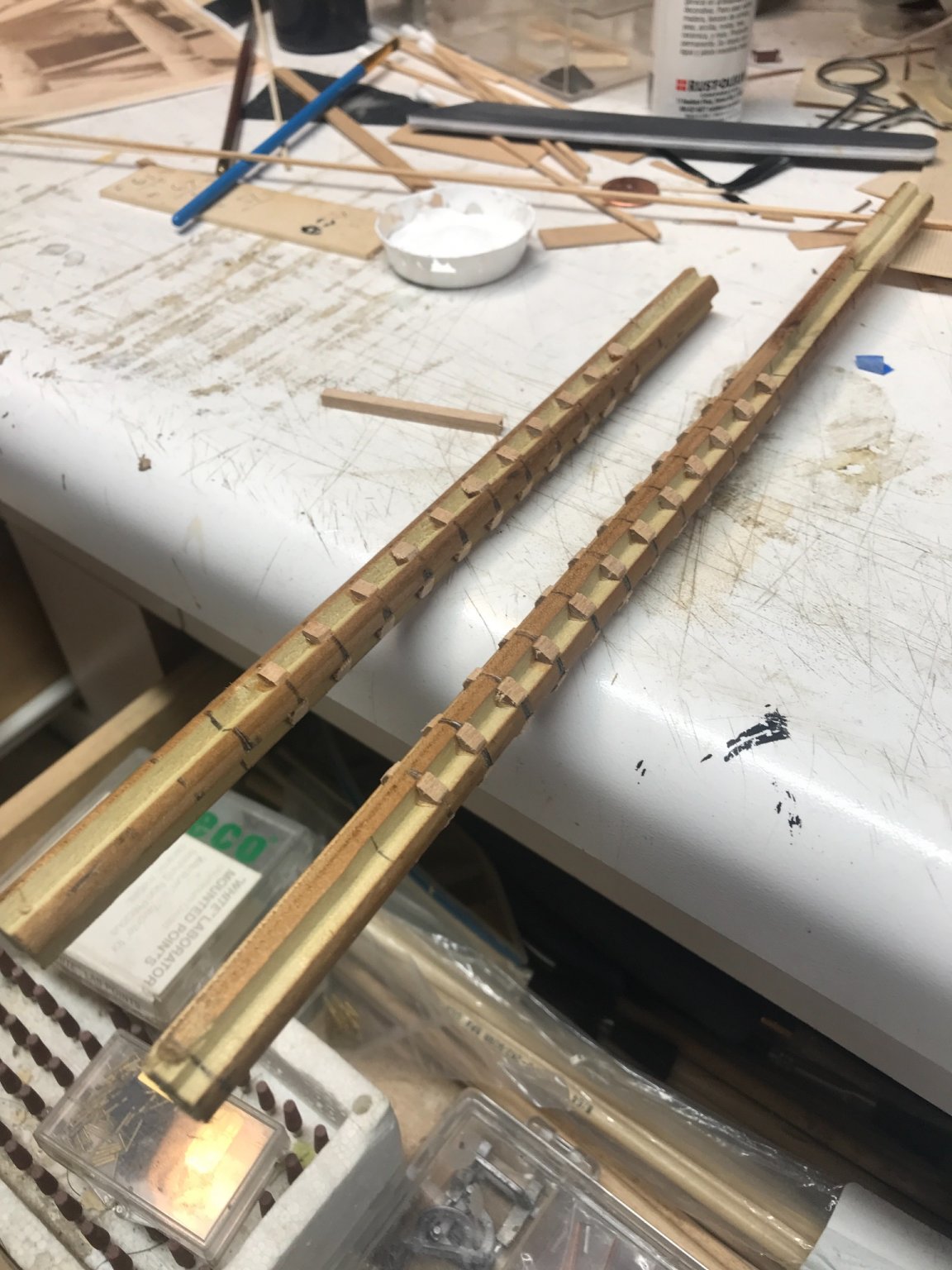
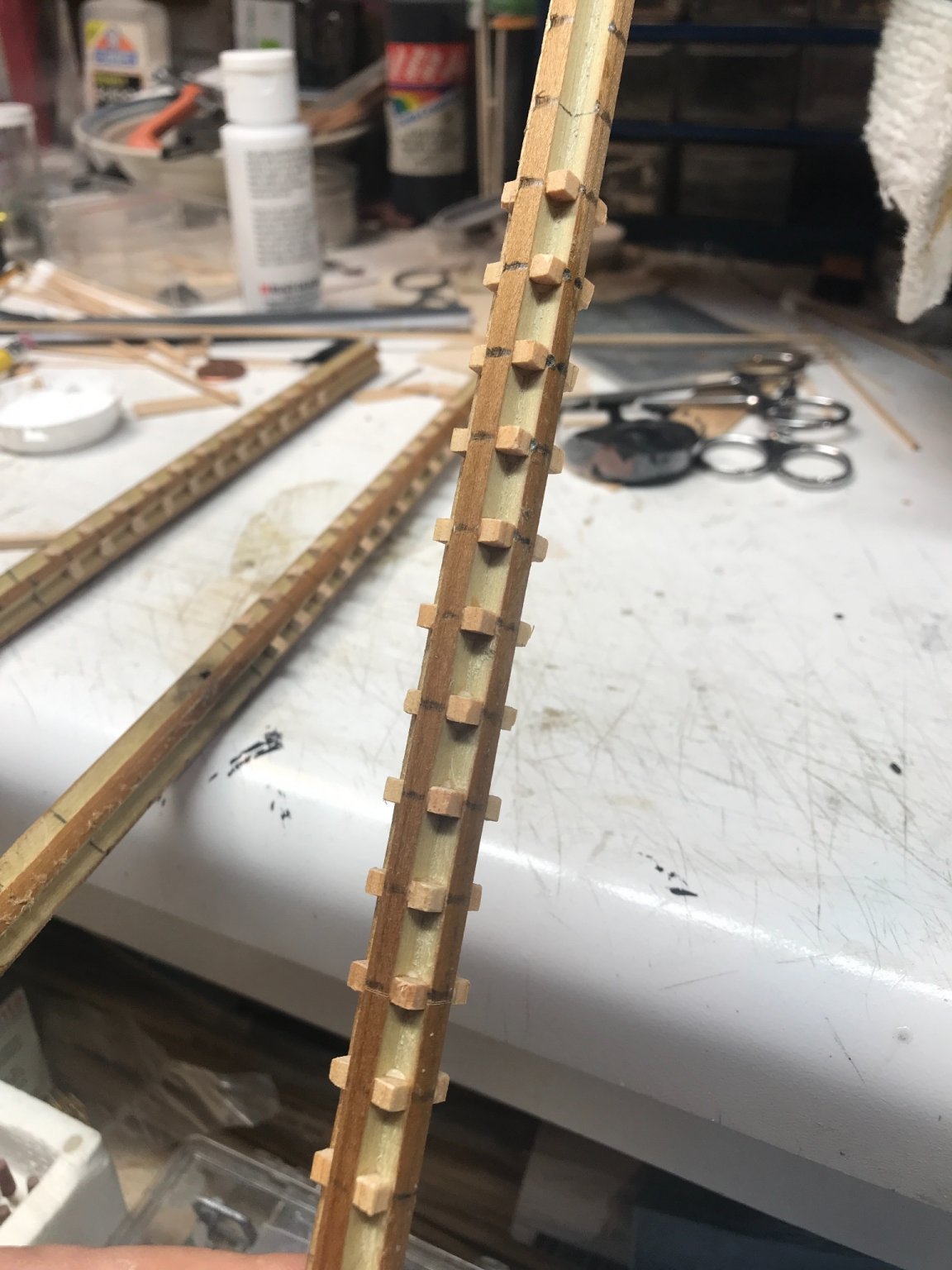
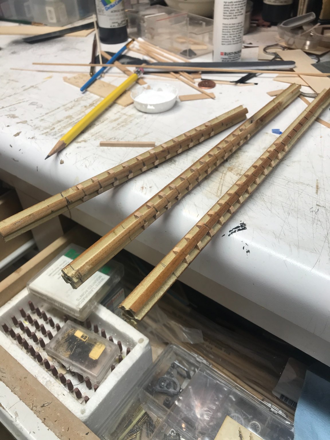
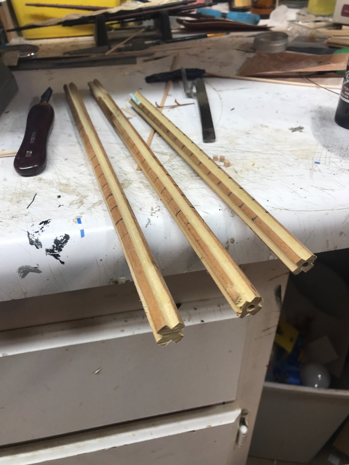
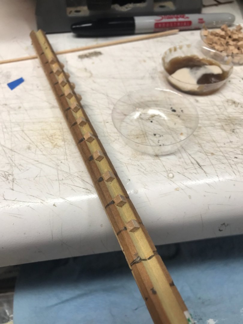
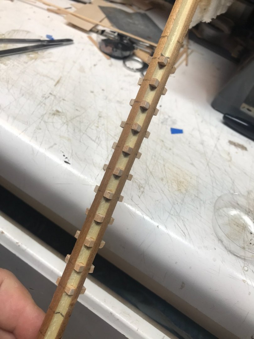
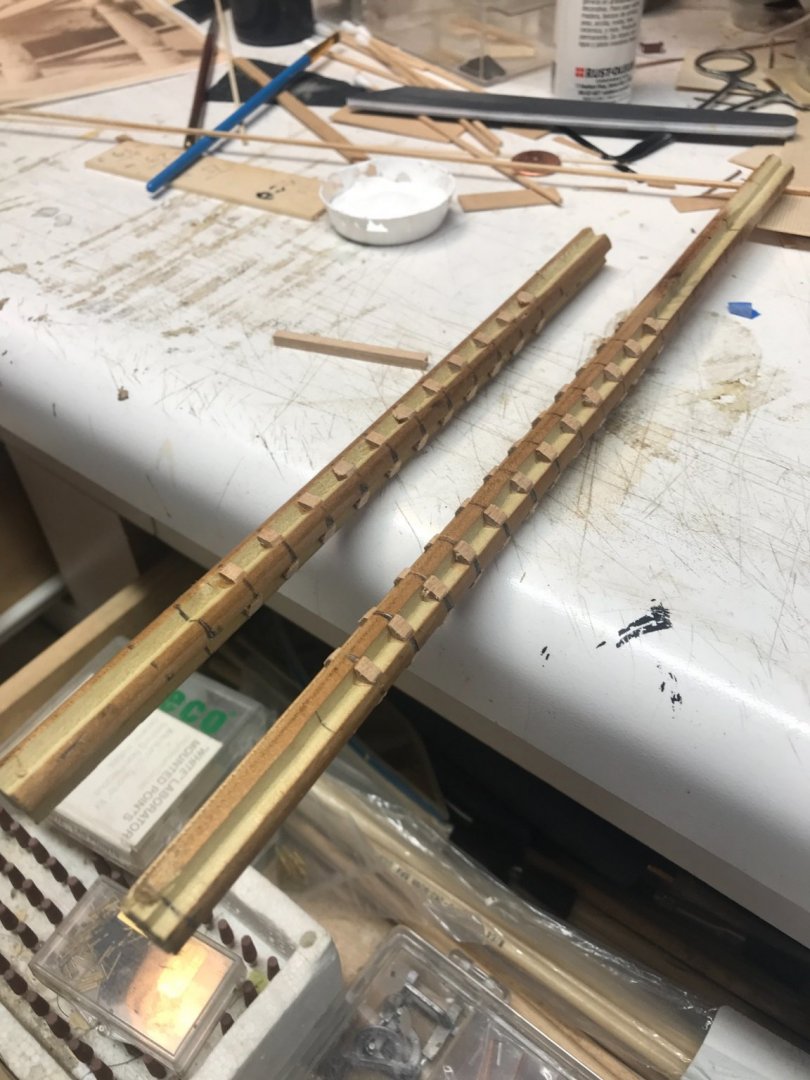
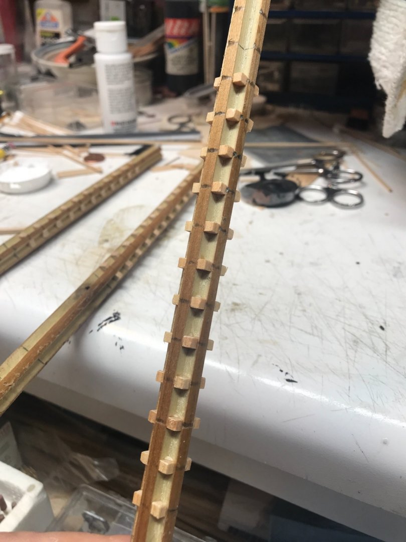
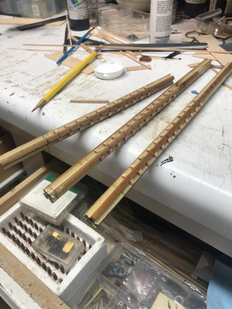
Next are several photos showing all of the chapel spacers glued into each mast . I will now take all the masts out and turned them on the lathe. First I sanded the high edges of, so as not to create undue stress while turning to the proper diameter. Rob
- 3,560 replies
-
- 4
-

-
- clipper
- hull model
- (and 2 more)
-
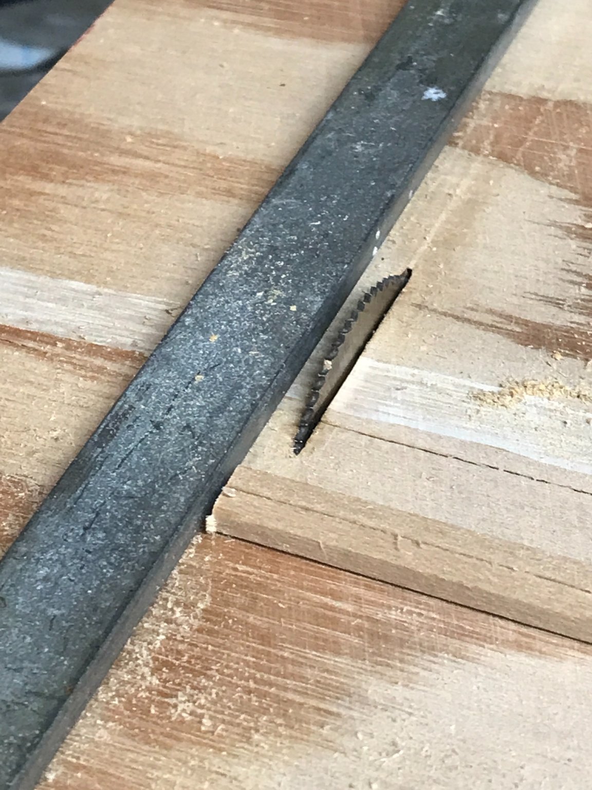
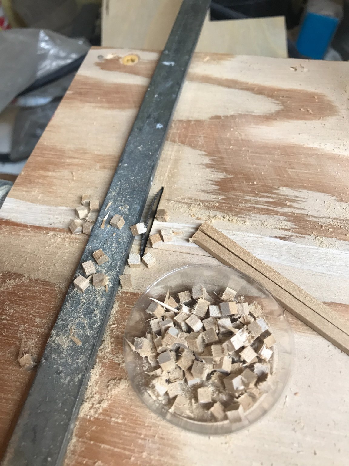
Next I set up the mini table saw and began to cut the spacers


- 3,560 replies
-
- 4
-
-
- clipper
- hull model
- (and 2 more)
-
Well here we go. I firstI took the wood over to the router table and cut in the four notches.
- 3,560 replies
-
- 3
-
-
- clipper
- hull model
- (and 2 more)
-
Hopefully I will take more images this time around. Rob
-
Like the Israelites, it was self inflicted…….and again, like the Israelites, only a remnant made it into the promised land. Shedding off our wandering , we entered into Glory’s rest…… mmmmmmmm. Rob
-
That, right there my friend, is clear as crystal...... Thanks, Rob
-
🤪 66' fore mast from deck, 72' main mast from deck, and 61-3=58' for mizzen from top of carriage house roof. It's like extracting a tooth slowly...... We'll get there, but we're gonna feel a little pressure...... Thanks for all your help. I'll use dead reckoning to determine the actual length of the doublings....based upon the known distance of 3" of distance between each mast band.
-
66', 72', and 61' is the actual length. Round Banded portion and the square banded doubling portion? The 5' addition that you added was that for the distance of the doubling portion or something else? Rob
-
OK......As much as I dooly appreciate all the fine mathematical wizardry, and how much sincere thought went into factoring in keel and backbone dimensions, which directly contribute to mast total length....and how much I am amazed at your dizzying intellect in compiling all this rich data, basically I'm a simple man...and a simple length for each mast from the deck to the mast cap would suffice for my simple purposes. I gather that the actual length of the masts (from deck to mast cap) are now 49', 55', and 47' respectfully.......is that correct? Rob(Not to be disrespectful in any way)
-
63.5, 69.5, 58.5 Riiight. Rob
-
Good mathin....... Rob
-
I thought the mast measurements were from deck level for the lower masts? That is all I really need......right? My calculations from my last build, gave the mast length from Deck level to top cap of the doubling. Rob
-
I don't want to find a rare colorized image of her some day....that will probably blow everyone away. I'm sorry I haven't put any work into Glory for a week or so. We watched the 5 grandbabies last weekend(I took Friday off), and this week has been delivery of gravel...grading..cleaning up foot deep piles of leaves and.....well...I barely had the time to go to the bathroom. However...I will go and get the dowel material needed and I will work(I took this Friday off) all day on the lower masts, getting them cut, turned and chapeled. I hope to *bust them all out. Once done...I will follow the construction process I used building the mast of the Great Republic. All done off model. Thanks, for your continual encouragement. Generally I do not have a second set of eyes(3 sets in this case), keeping the details fervently in front of the construction process.....checking(double checking) accuracy. Now that the construction of the hull, deck furniture, houses is all complete.....I can settle back into the routine of constructing her masts and spars and the miles upon miles of rigging that will be necessary to make her complete. These items are not so much ship specific, so my experiences in fabricating them will make this job relaxing. Rob
- 3,560 replies
-
- 2
-
-
- clipper
- hull model
- (and 2 more)
-
Keith…… glad you are moving forward. I love rigging and so much is typical, so you should have good success. Rob
-
Well Pat, I can correct the mast issue…….but the other issues are what they are. With that said, it was the idea of making a true to reality hull of Glory…… and that was the original intent. These minor(I call them minor), elements are not deal breakers in the least. Only true Glory geeks would make them so, and even then it’s not the end of the world. Thanks for the continued confidence. Rob
- 3,560 replies
-
- 1
-
-
- clipper
- hull model
- (and 2 more)
-
I'm glad he approves...even though I have managed to reproduce some blatant errors Namely the carriage house aft reduction and the forecastle height discrepancy. I made these egregious mistakes, even after having all the correct information right in front of me. My anxiousness to get her built, violated several of the greatest modelers tenants. Patience and accuracy. Today I re-evaluated my composite mast construction technique and, again, I think I am going to change the construction process up again. I'm going to work from dowel material and use my table router to remove the chapeling material. Turning the mast on the lather from glued square stock resulted in slightly off center round masts. It is slight and thusly is caused the 4 chapeling segments to be slightly unsymmetrical. It is hardly noticeable, but to me it is unacceptable. This is what I referred too as slight blemishes, in an earlier post. I'll set up a jig on my router table and cleanly cut even grooves. This is how I did it on the masts for my Donald McKay clipper...but I used a home made mini table saw then. This go around I will use a nice router bit. Then as before...add the chapeling spacers and again, paint, and sand till clean and smooth. Things will run truer on the lathe this time....resulting in much nicer composite masts. IMV. Rob
- 3,560 replies
-
- 3
-
-
- clipper
- hull model
- (and 2 more)
-
Thanks Rich. I haven’t been in contact with Mike for a while. I hope he enjoys the images you sent. Rob
-
These curvilinear sterns still don’t match Glory’s images. Plus I think we are missing the greatest comparative discrepancy. Glory was a full bodied MEDIUM clipper. All of these examples presented are from extreme clippers. An entirely different MODEL of clipper. Requiring completely different structural considerations when wood was the primary building material. Something to think about. Rob
-
Well, if we look up the word Curvilinear. We will see that it means: Formed, bounded or characterized by curved lines. In essence, it is s subjective word. A word describing curved lines that are linear....(Together), but not straight. I see her curve as not a true spherical, but more oblate...where the apex of the fantail is the FLAT pole point and then it forms spherically as it terminates at the flat sides. I see why Duncan used the subjective term Curvilinear....the current vernacular or a looser translation would be...Roundish.... This all plays into the spectacular design parameters that McKay availed upon. His entry and exit designs were his *trade* secrets and since, apart from his two pares of sister clippers, Star of Empire/Chariot of Fame and Commodore Perry/Japan, he never reproduced exact duplicate designs. He kept improving, changing, experimenting. Circlic designs are far more robust. Rob
-
The lower angle is most advantageous because it aids in identifying the stern as more calendrical then abrupt with oblate edges. Clues, clues, clues help evaluate reality. Rob
-
This circle matrix is representative of a vertical circle under the stern......I wanted to use a visual to aid in identification of what distortion hides. Rob
- 3,560 replies
-
- 1
-
-
- clipper
- hull model
- (and 2 more)
-
Why I still reserve the right to think the stern is more round then oblate on its edges. I used a simple drawing program to illustrate the more circular stern and slightly flat on the central fantail. I used a circle templet and imposed it against the rail on the starboard side and it matches pretty close. Follow along the edge of templet and the edge of the rail and the edge of the planksheer.

-
Now that looks much better, that I can agree with. Could be even slightly rounded with that flatter fantail. Great job Rich. I like it. Rob(but who am I)
- 3,560 replies
-
- 1
-
-
- clipper
- hull model
- (and 2 more)
-
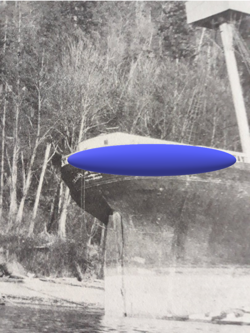
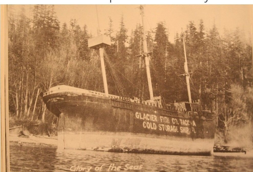
I agree about the carriage house curving to accommodate the curve of the hull. I made my carriage house curve, but not enough, and I didn’t make the roof follow the slight curve of the walls, so it gets unnoticed. However, that is where we part. The image of her on the beach shows clearly, if you follow her rail, that it slowly curves around her stern. Look closely….see her starboard rail curves slowly…….not abruptly as depicted, but slowly. Im still convinced she has a nearly round stern , slightly ablate at the fantail, or slightly “curvilinear”. Kinda Like what you depicted but far less extreme Sorry . Rob
- 3,560 replies
-
- 1
-
-
- clipper
- hull model
- (and 2 more)
-
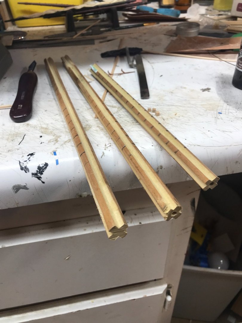
They are not perfect, there are slight imperfections in the paint and turned surfaces. When it dries I’ll work it a bit more. Rob