HOLIDAY DONATION DRIVE - SUPPORT MSW - DO YOUR PART TO KEEP THIS GREAT FORUM GOING! (89 donations so far out of 49,000 members - C'mon guys!)
×


Tomculb
-
Posts
345 -
Joined
-
Last visited
Content Type
Profiles
Forums
Gallery
Events
Everything posted by Tomculb
-
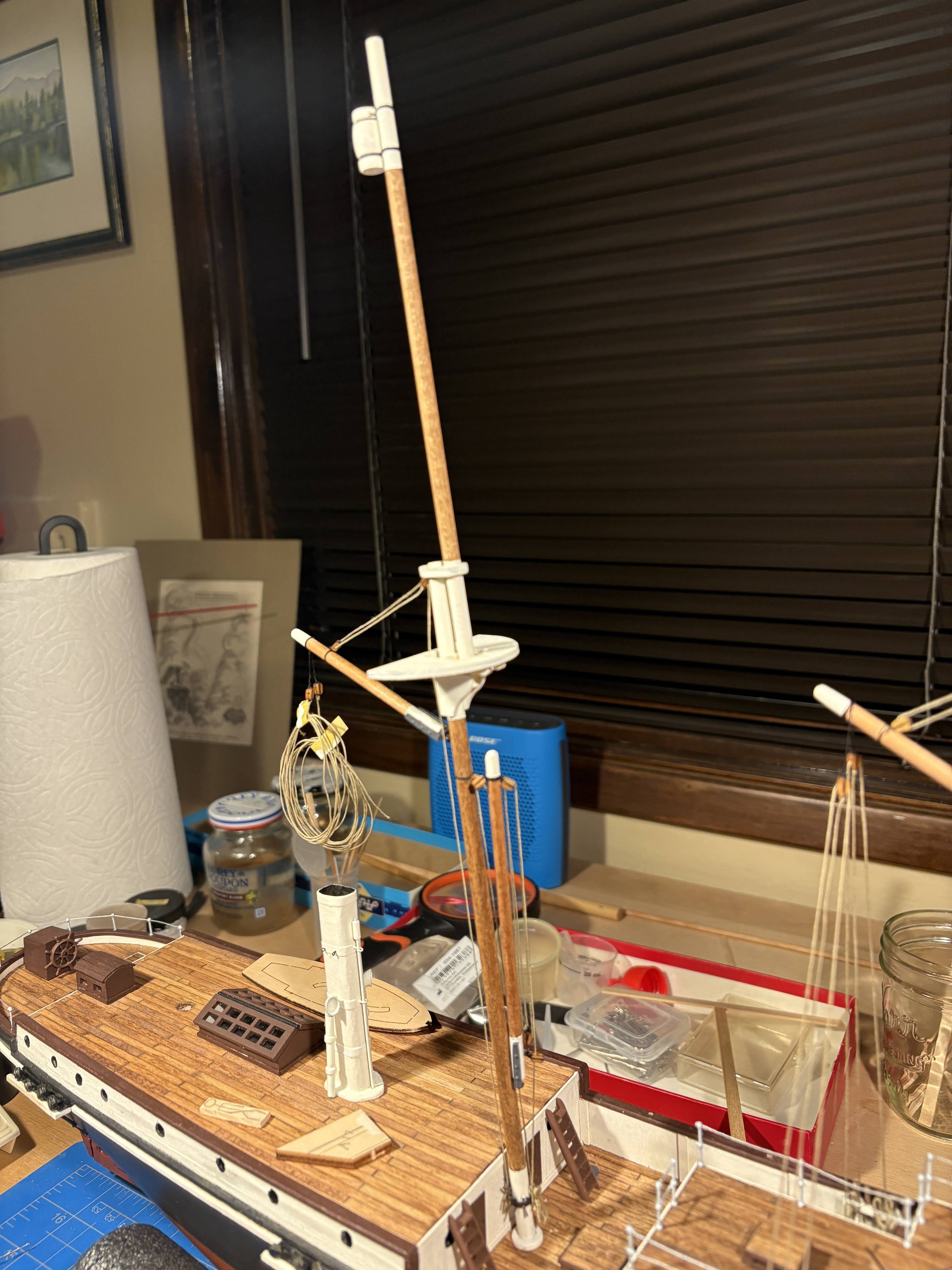
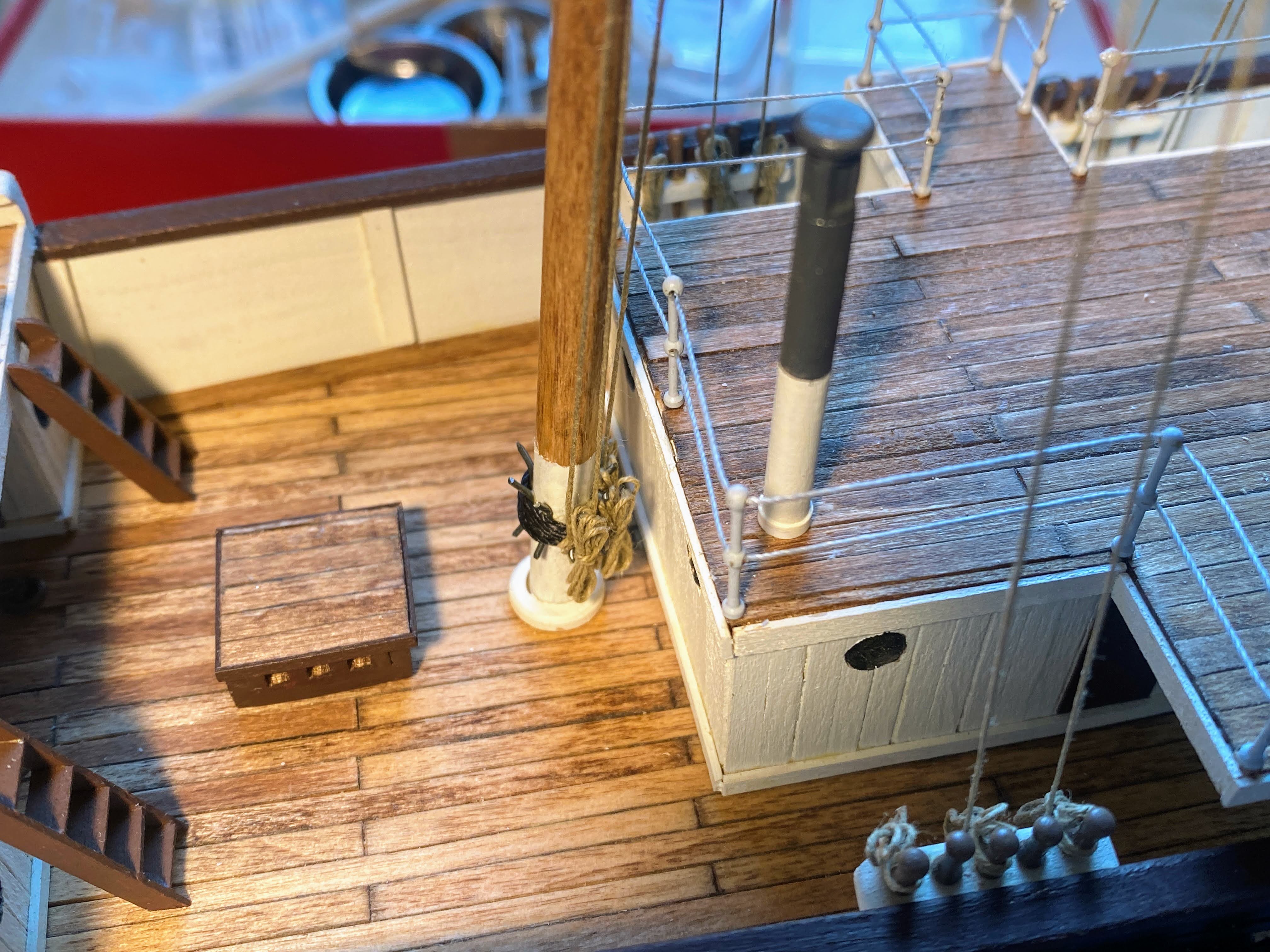
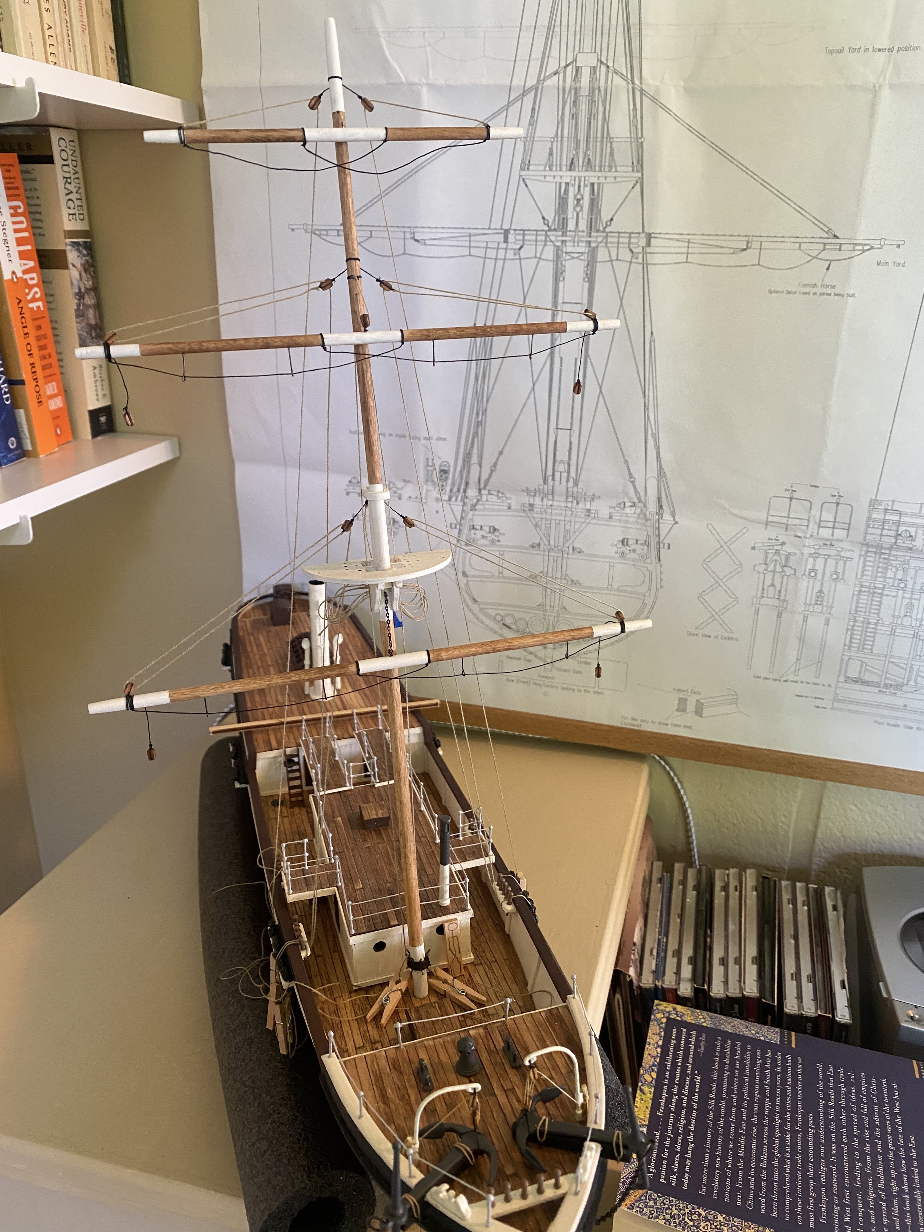
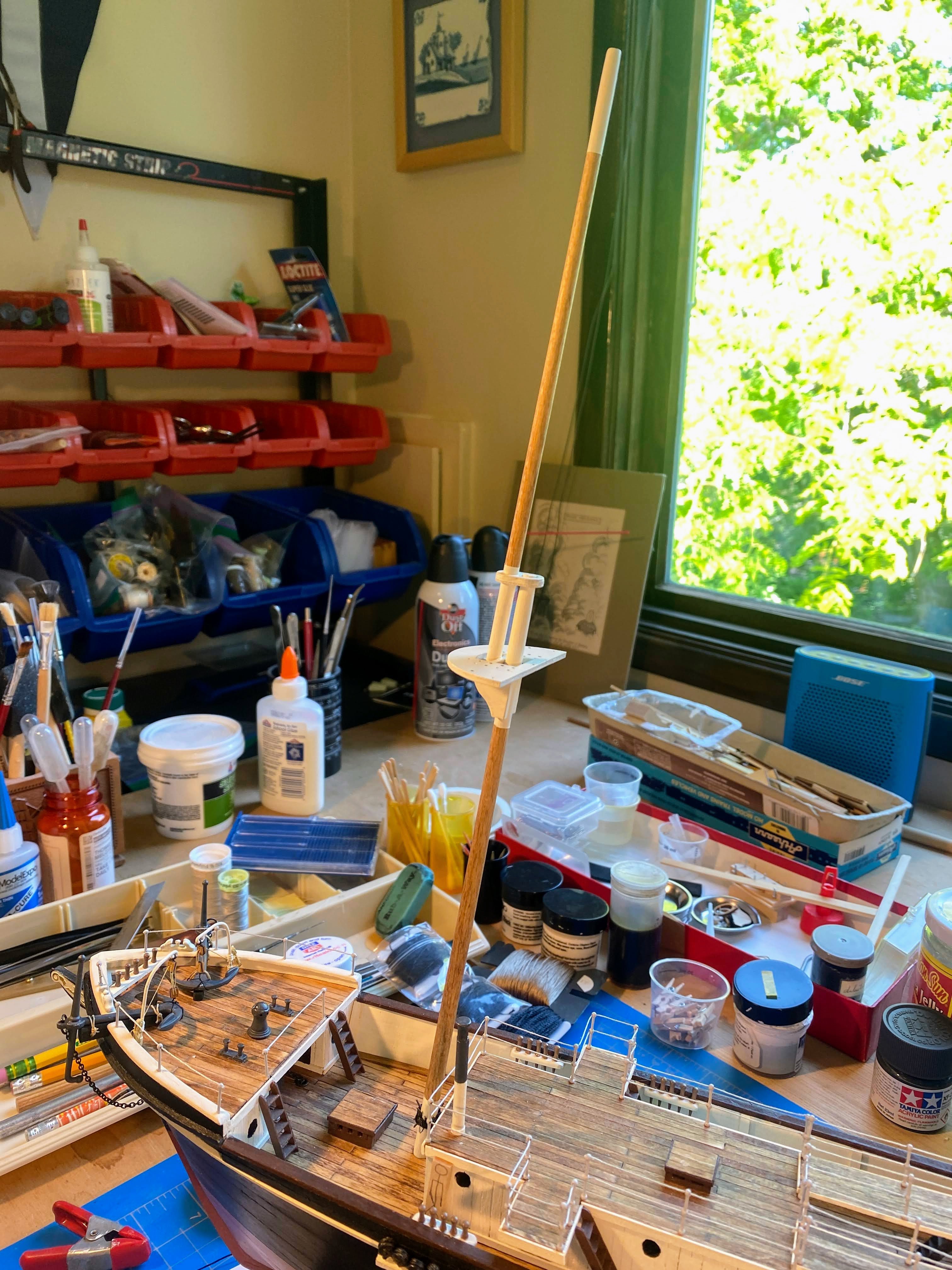
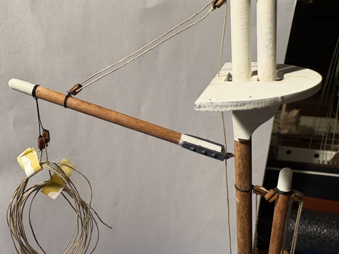
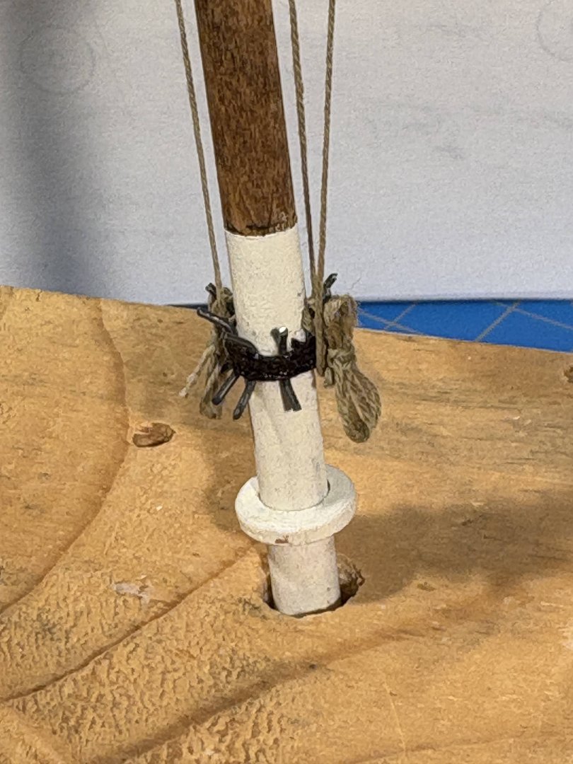
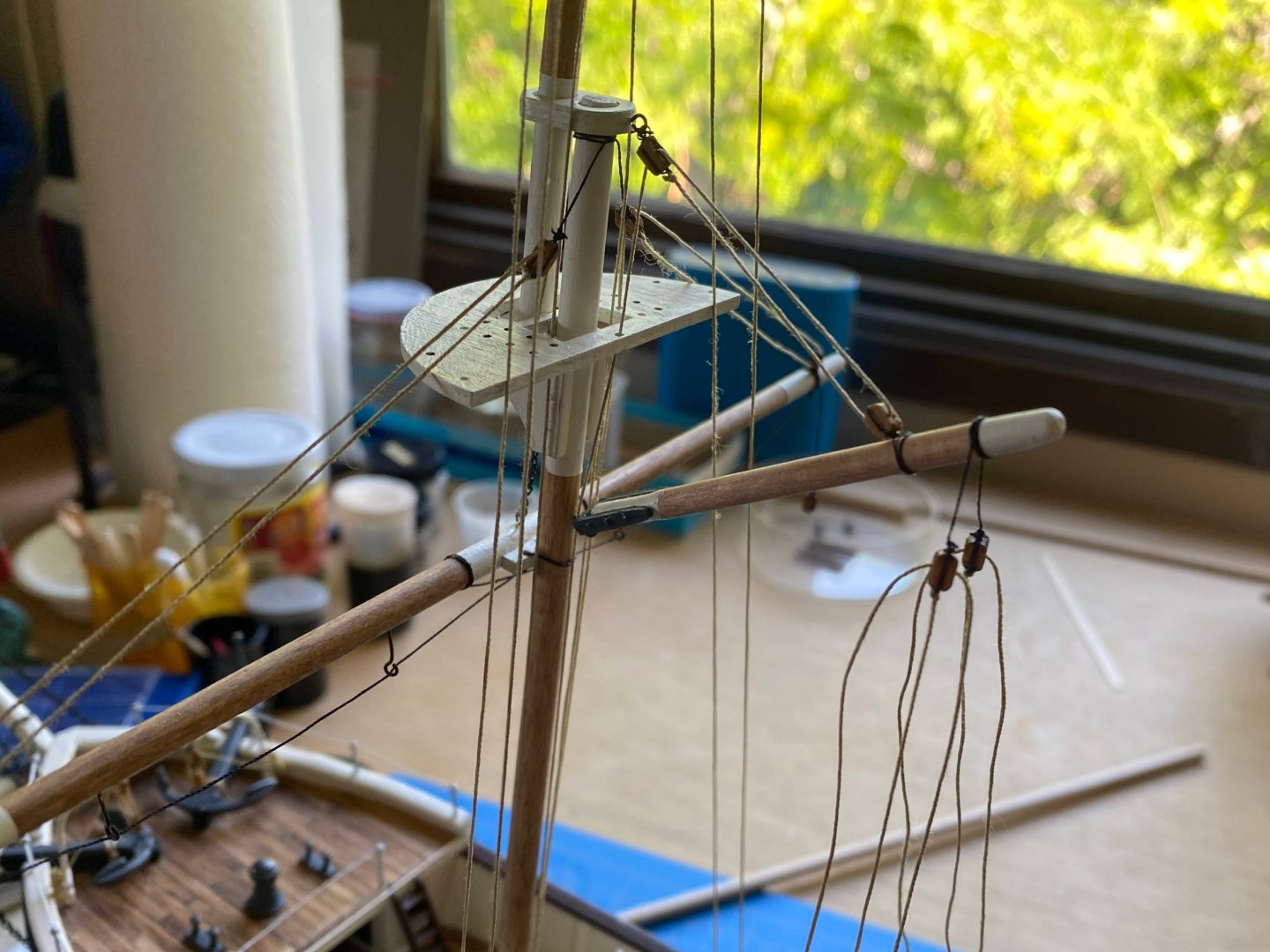
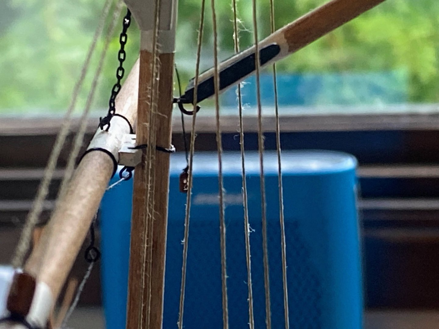
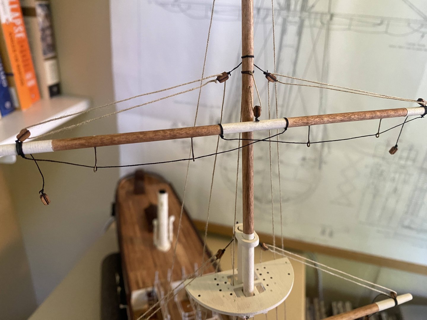
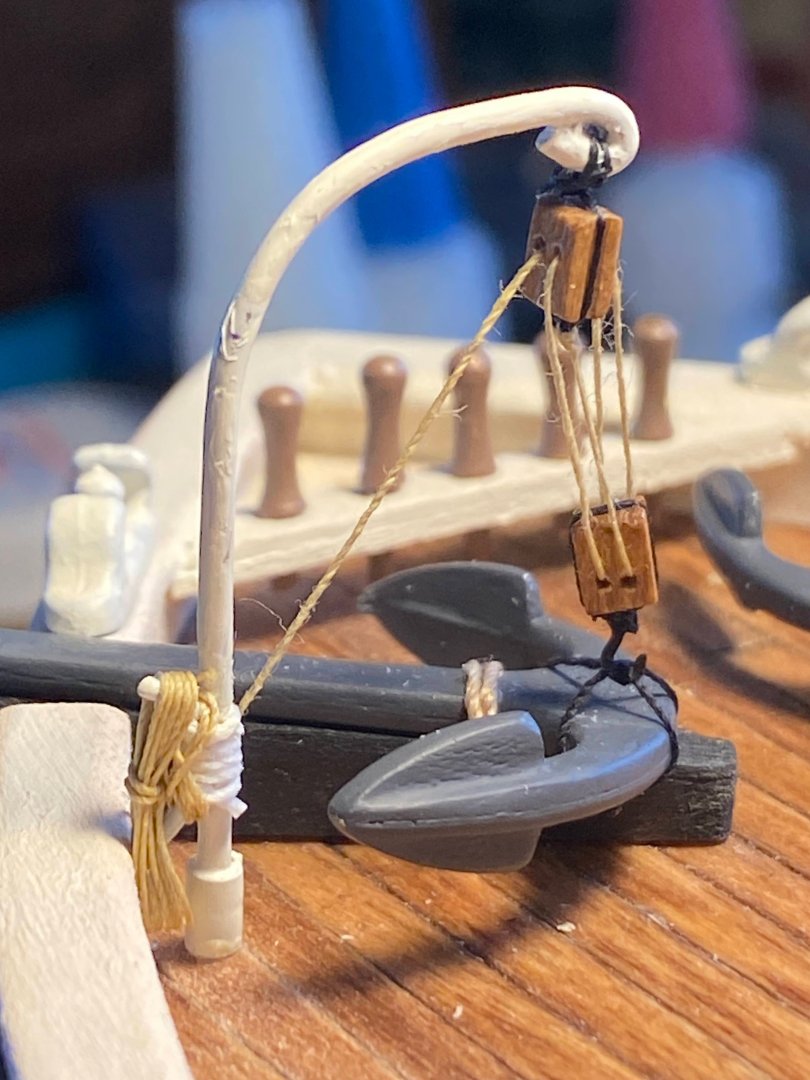
 I have built the mainmast and installed the gaff, crane and crow’s nest barrel. One of the pictures below shows the mast installed on the ship, but it hasn’t been glued there yet. Among other things, I will probably rig the upper shrouds, futtock shrouds and ratlines with the mast temporarily installed in a 2x4, which makes it more accessible. The only thing deserving comment at this point is the crane/boom, which I thought seriously about not installing. I think I’ve only seen one or two photos in which it appears, and I’m guessing it would be used only when loading things on and off the ship. It might even have been removed except when needed. The lower stay between the foremast and the main mast would have to be unrigged for the crane to be useful. As you can see below, I chose to rig it pulled up tight against the mast. I have two sizes of photo etched hooks left over from prior builds, I feared the larger ones were too big, and I used one of the smaller ones. Now I think that was a mistake as it can hardly be seen, but not important enough to redo. OcCre has the loose end of the hook’s tackle tied to an eyebolt at the boom’s inner end, a place which probably couldn’t be reached by anyone. I ran it through a block on the inner end of the boom, then down to the forward cleat on the spider band at the bottom of the mast. That’s also where the working end of the boom’s peak halyard is secured. There’s really no other good place to secure it. There are 8 cleats on that spider band-- one for the gaff peak halyard, six (three on each side) for the foremast braces, and one for the crane rigging.
- 206 replies
-
- 4
-

-
- Endurance
- Shackleton
- (and 2 more)
-
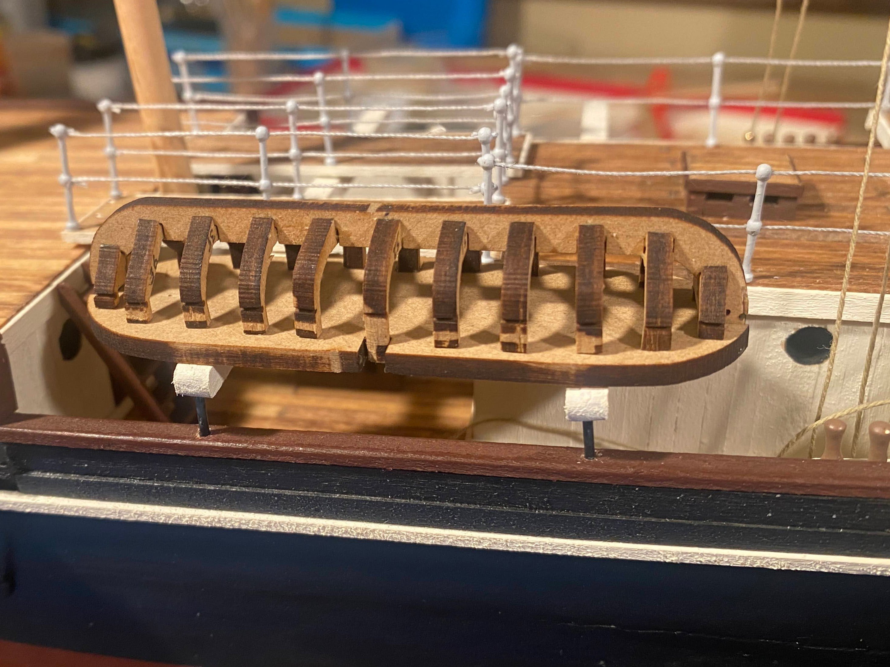
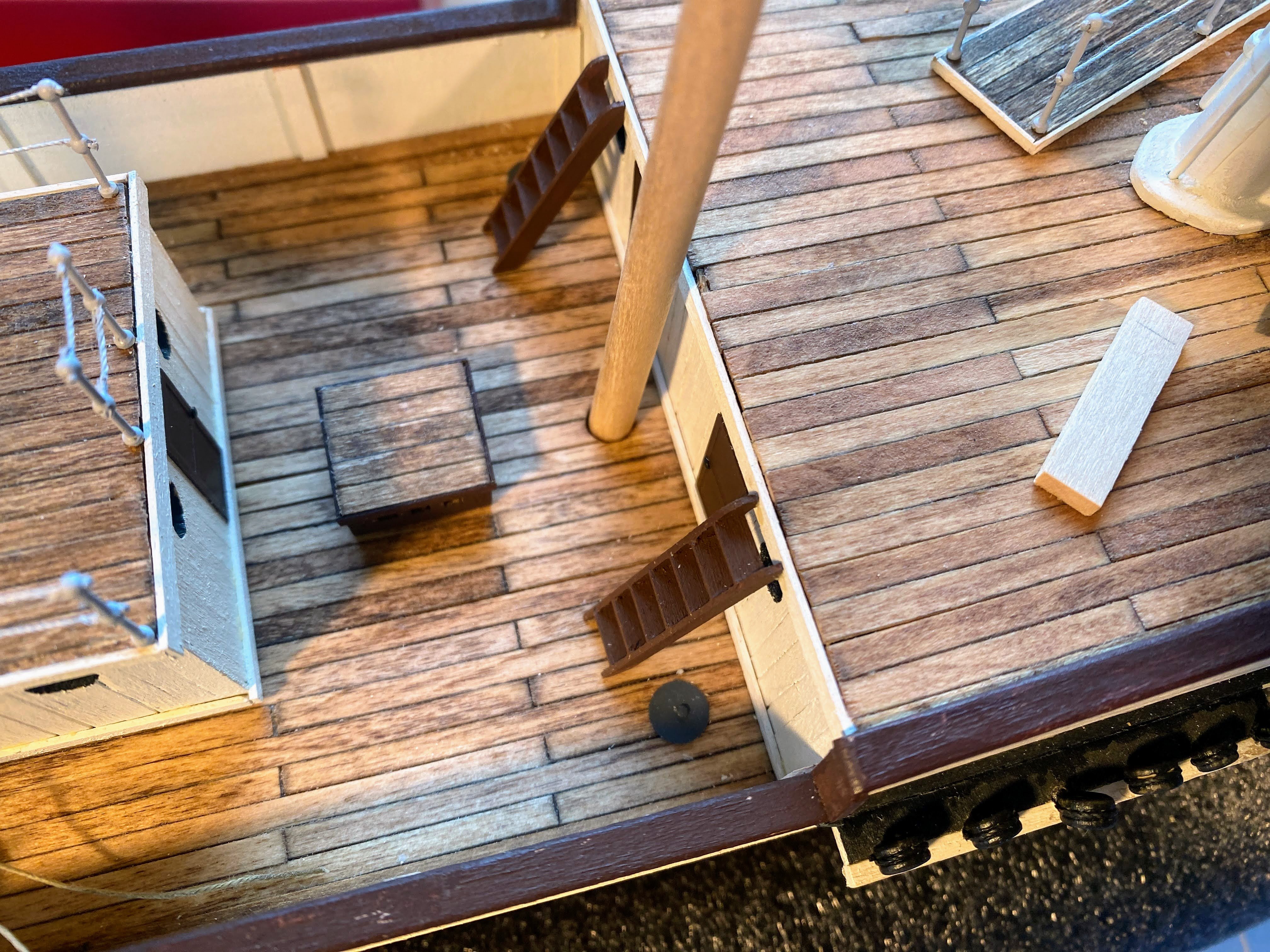
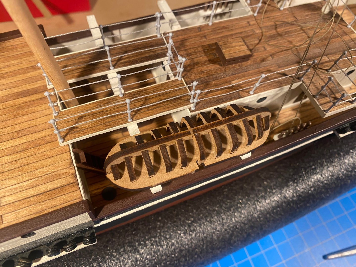
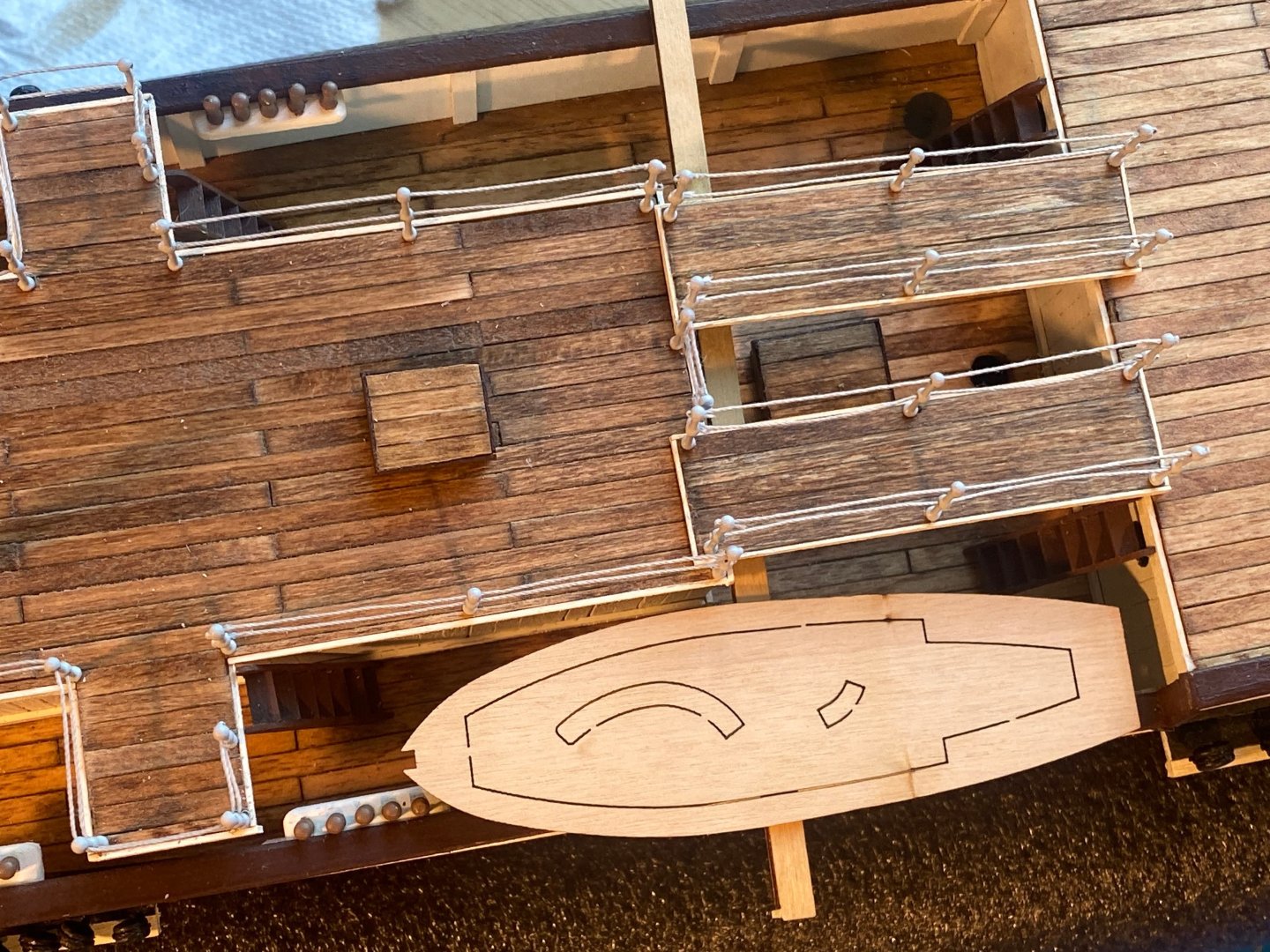
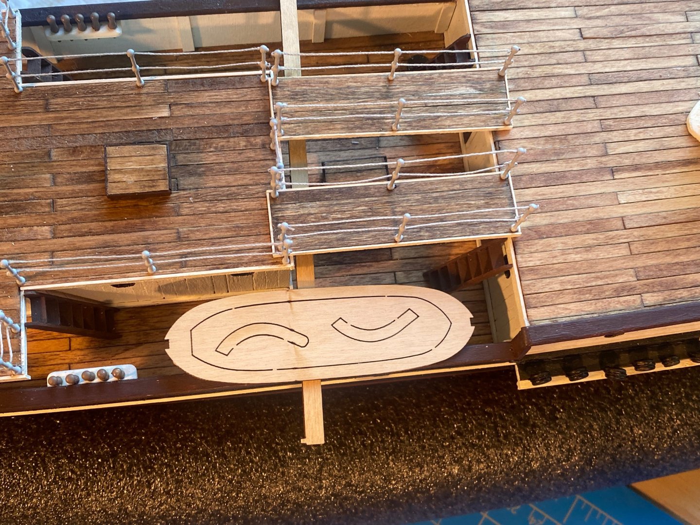
Unrelated, but my wife and I just returned from a trip, and I posted here about the amazing ship model collection at Amsterdam’s Rijksmuseum. I mentioned previously that I intend to place the forward ship’s boats on racks inboard from the bulwarks, instead of outboard hanging from davits as OcCre intends. The ship’s plans I refer to and a number of the Frank Hurley photos show the forward boats stowed that way. Before leaving on our trip, I built the basic frames for this stowage, and I partially assembled one of the boats to see how everything would fit. I had already determined that the smaller boats fit better forward, with the larger boats aft, the opposite of the way OcCre places them. Neither these racks nor the deck gangways are glued in place yet. I will assemble, rig and install the mainmast before these things are glued in place.

- 206 replies
-
- 3
-
-
- Endurance
- Shackleton
- (and 2 more)
-
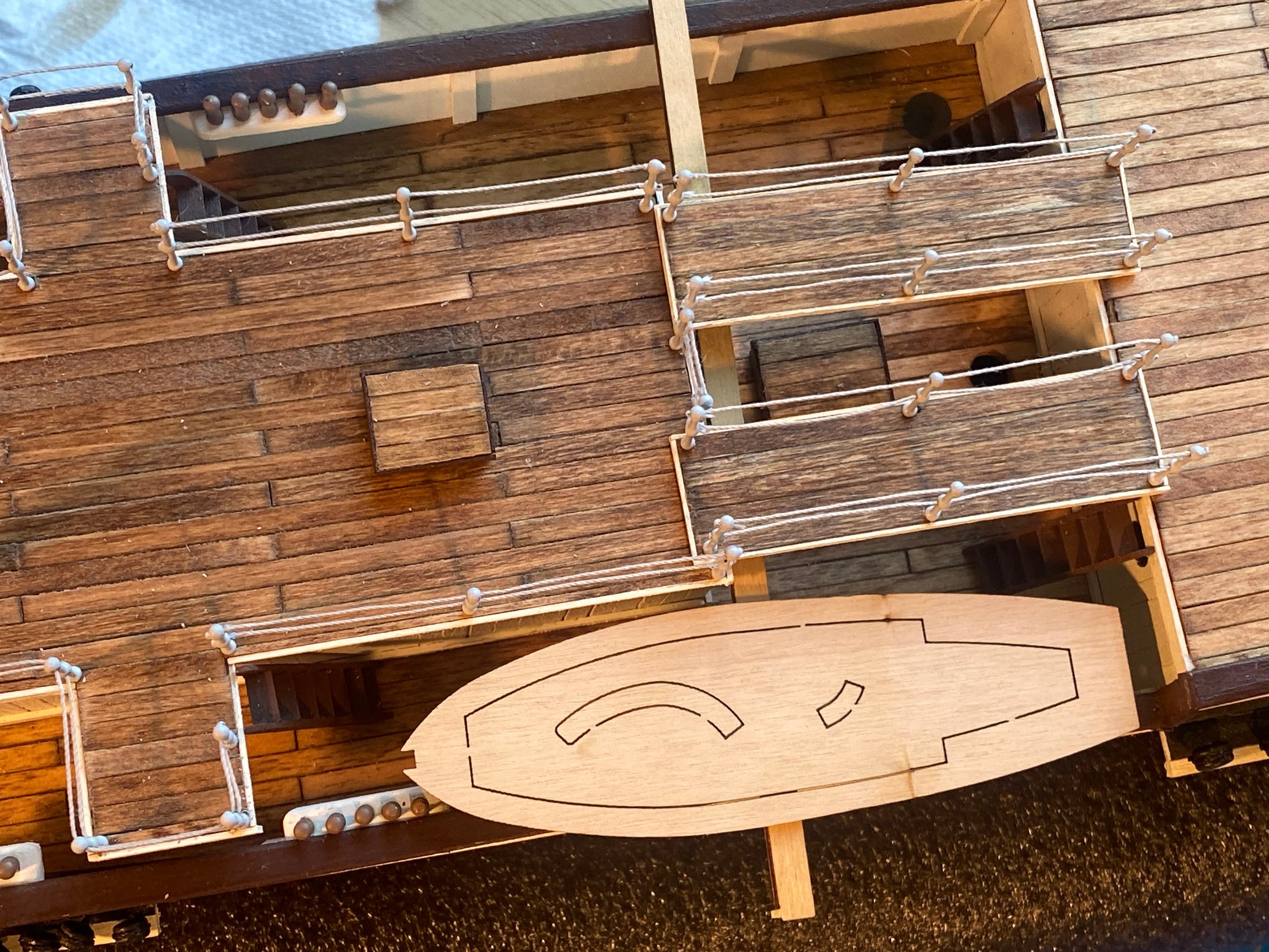
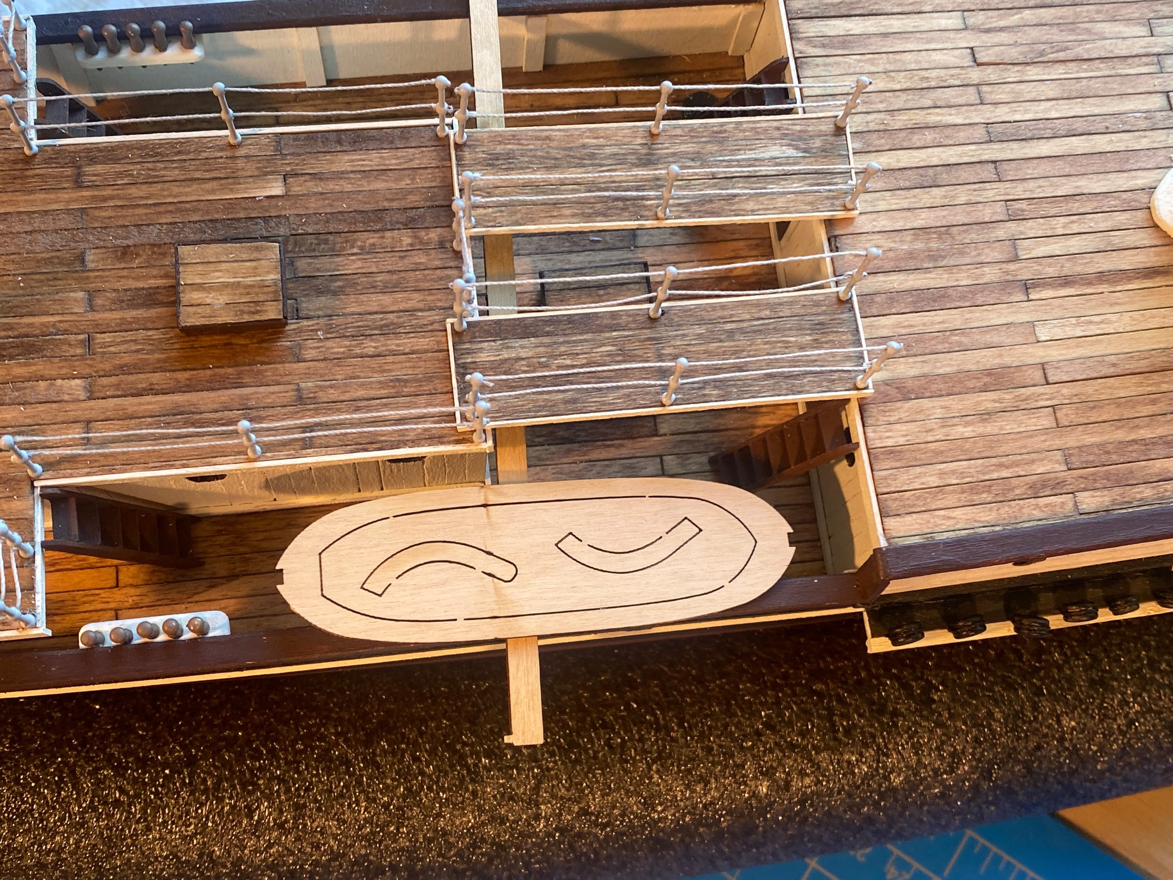
Thanks SHJ. I wish I was smart enough to deserve the credit you gave me. Actually I didn't paint those lines at all. What I did is find some grey thread which I used untreated, then mixed some white and grey paint to give the brass stanchions a color that is at least close in color to the lines. The goal was to have the lines look like wire cable.
- 206 replies
-
- 2
-

-
-
- Endurance
- Shackleton
- (and 2 more)
-
At long last the time has come to glue the deckhouse in place. As I mentioned in an earlier post, OcCre shows a stay running from half way up the main mast down to an eyebolt at the front of the deckhouse roof/deck. Stays are frequently rigged with a lot of tension, they should be fixed to something having plenty of strength, and what could be stronger than the base of Endurance’s foremast? I stared at it for some time, trying to figure out how I was going to get my big clumsy fingers in there to wrap the thread around the mast a couple of times and then using thin thread, tie half a dozen or so half hitches around the two parts of the stay, all without disturbing the lines tightly secured to the mast’s spider band and the bulwark pinrails. Eventually I decided that it can’t be done (only barely acknowledging that it can’t be done by me). So I installed an eyebolt to the deck of the deckhouse as instructed and secured one end of the stay to it. I then loosened the gaff sheets to make room, applied glue to the bottom of the deckhouse, gently slid it in between all the running rigging, and glued it in place. I was then able to tighten and secure the gaff sheets to the pin rails and glue the remaining ladders in place.

- 206 replies
-
- 3
-
-
- Endurance
- Shackleton
- (and 2 more)
-
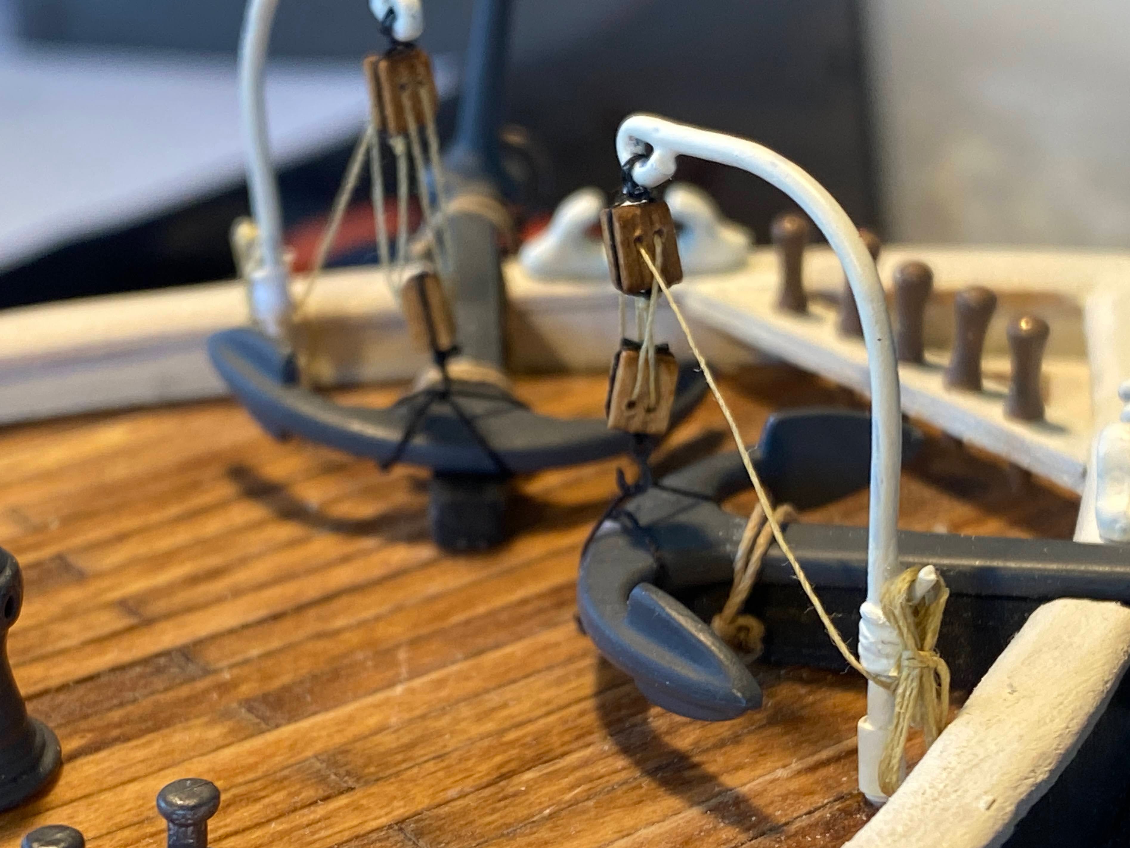
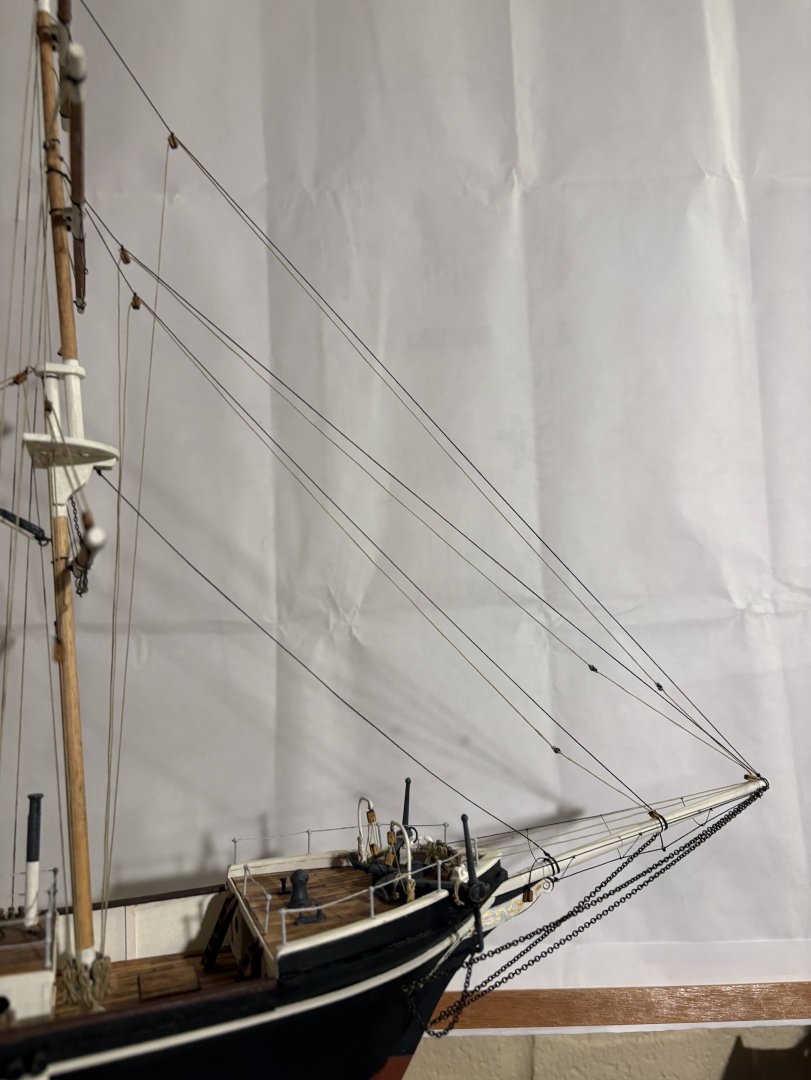
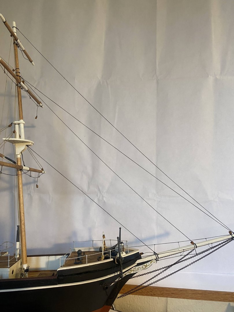
After some delays, I have now finished rigging the headsail halyards and the downhauls. There are four headstays. OcCre has you install running rigging and sails on the inner three, consistent with plans and some photos I have. Other photos show running rigging on the outer three. For no particular reason, I chose to do the latter. In each case, OcCre's instructions show a halyard and two downhauls on each designated stay. One downhaul is attached to the head of the sail and one attached to the tack. I have been on many sailboats but never one with a downhaul attached to the head of the sail; the weight of the sail was always sufficient to bring it down when the halyard was released. Also, the tack was secured to a fitting on the bow (on the bowsprit here), and the purpose of the downhaul was to adjust the tightness of the luff (leading edge of the sail). As such, the bitter end was attached to the bow, and the line ran up through a grommet a short distance up the sail and then back down to a block and then aft. But then the largest sailboat I’ve been on was about half the size (by length) of Endurance and about half a century newer, so what do I know? In any event, I opted for one downhaul and linked it to the halyard. Keep in mind that I decided not to install any sails. The loose ends of the downhauls and halyards were then secured to the forward pinrail and the foremast’s spider band respectively.

- 206 replies
-
- 4
-
-
- Endurance
- Shackleton
- (and 2 more)
-
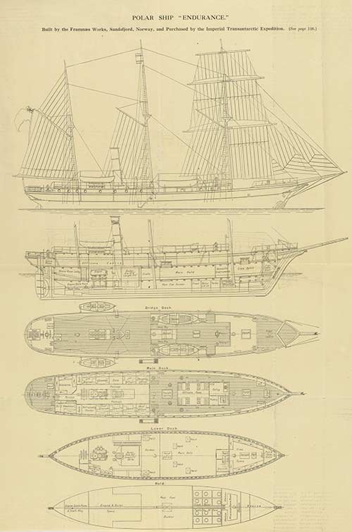
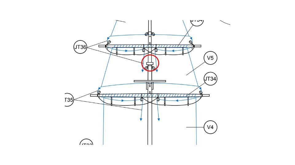
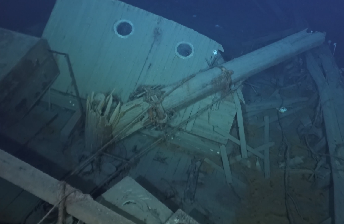
Putting aside the things I was thinking about in my last post, I installed the head stays between the bowsprit and the foremast. For thread I used a very dark brown by Gutermann that I ordered online. It turned out to be too dark, brown instead of black only on close inspection, but I used it anyway. In the photos below it certainly looks black. The OcCre supplied thread is a mid brown color; not dark enough in my view. It is also half a millimeter thick, which translates to almost 1.4 inches thick on the real ship. I doubt that Endurance’s standing rigging was that thick. I’m not sure what the thickness of the Gutermann thread is, but it is something less than half the thickness of the OcCre thread. OcCre has the lowest stay secured to the mast at the mast cap. As can be seen in the second picture below (from the rigging instructions), that would put the stay right smack in the middle of the topsail. You would have to cut a hole in the topsail for the stay, which makes no sense. I ran it to the mast at the foretop.

.png.d015d3ea7ebf78fcbd73e9536e38cec6.png)
- 206 replies
-
- 4
-
-
- Endurance
- Shackleton
- (and 2 more)
-
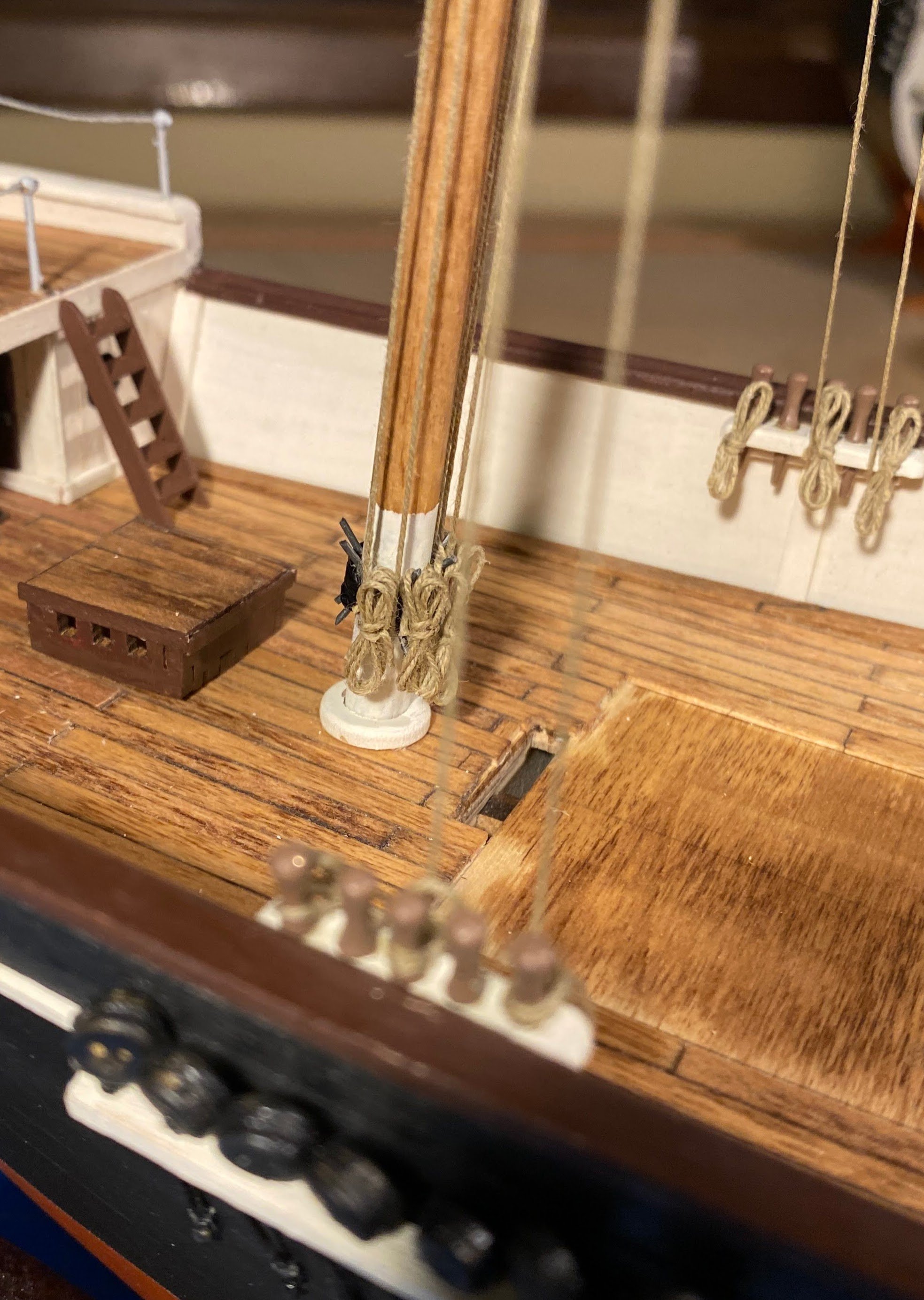
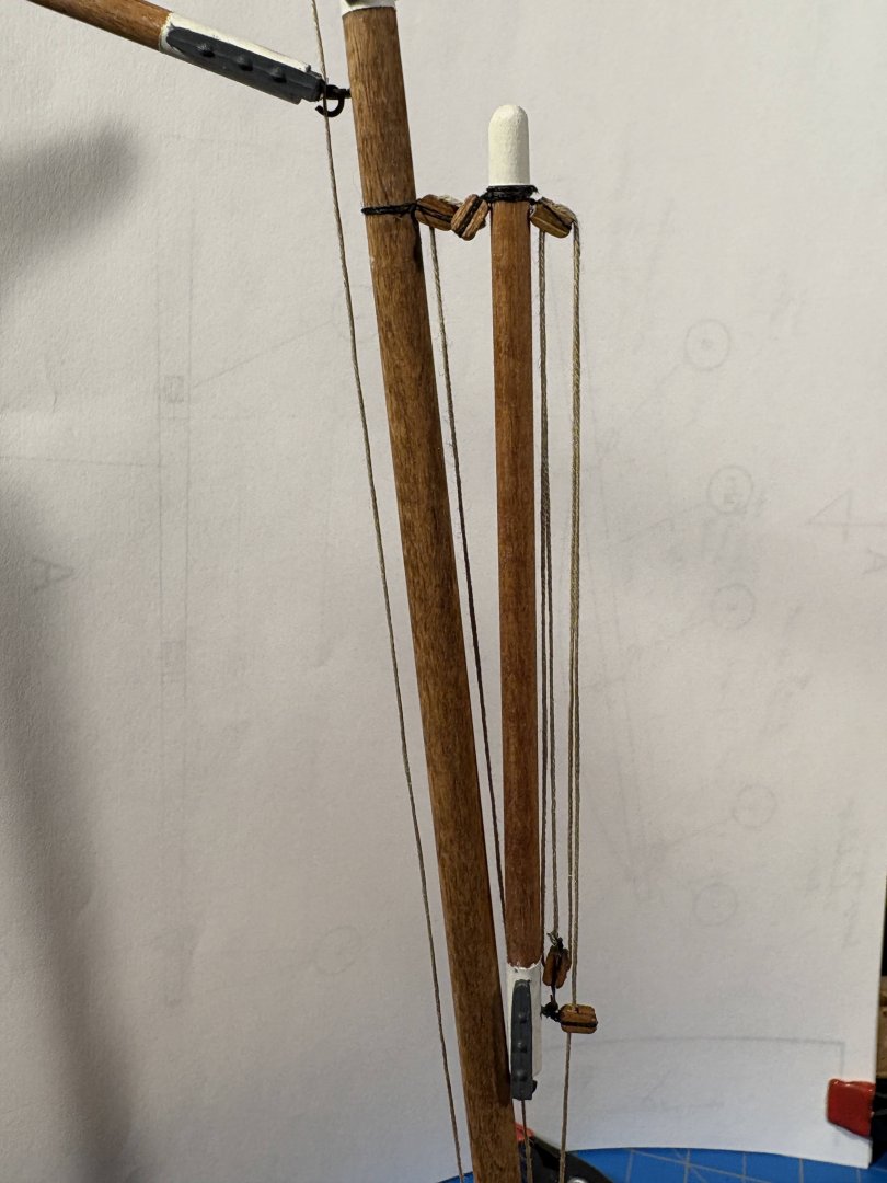
Progress report . . . I installed the gaff, with a couple of eyebolts imitating a gooseneck. I then brought the gaff peak halyard, the topsail and topgallant yard halyards, and the main spar lifts down to the cleats at the base of the mast, where they were secured. I then separately made rope coils and draped them over the cleats. That’s a total of five lines, leaving three cleats available for the headsail halyards. Since none of the installed lines are attached to the hull anywhere, I was able to do this rigging with the mast off the ship, which made things a lot easier. Then after securing the mast to the hull, I brought the topsail and topgallant spar lifts down to belaying pins in the bulwark pinrails, secured them and added rope coils. As I mentioned previously, the deck cabin is only dry fit in place, and removing it made it a lot easier to secure these lines and add the coils. I installed paralls at the back of each of the yards. Had I given it any thought, I would have installed them before installing any of the other rigging; securing them with the spar lifts and halyards in place made things considerably more difficult. The gaff sheets are still loose, but they do run through blocks I installed in the deck below the aft pin rails, where they will be eventually secured. Fortunately I recognized that putting the deckhouse back in place would be very difficult with those sheets fully rigged. Same issue as to at least one stay that will run between the mainmast and an eyebolt on the deck house deck (or as I prefer, to the foremast). On the other hand, with the deckhouse fixed in place, it will be a lot more difficult securing those sheets to the belaying pins as I intend to do. Hmmm . . . Some other issues I need to think about. . . As I said it was a lot easier securing lines to the cleats at the base of the foremast with that mast not attached to the ship. Most of the lines that will similarly be secured on cleats at the base of the mainmast (that is, the braces attached to the foremast yards), can only be installed with the mainmast installed on the ship. And the bulkhead immediately behind that mast obviously cannot be temporarily removed. Maybe I will secure those lines to the cleats first (before the mast is installed), then once the mast is installed run them up to, and attach them to, their yards? Or will I attach the lower end of the braces to pinrails I could install at the aft end of the bulwarks?? Or run them to the cleats on the mast as I originally intended after the mast is installed??? As did @HakeZou, I want to build cradles for the forward ship’s boats, stowed on board rather than hanging from davits. A number of Frank Hurley’s photos show them stowed that way, as do the ship’s plans I refer to frequently. Obviously they would need to be stowed in such a way as to not interfere with any rigging. As supplied by OcCre, the boats come in two sizes, with the forward ones being larger than the aft ones. After test fitting laser-cut one-piece railings for each size boat, I think I want to reverse that, as Hake did. Regarding those boats, someone(s) mentioned that ship's boat kits manufactured by Master Korabel and available in different sizes are much better than those included in this kit. I gave some thought to purchasing four of those kits, but everywhere I looked they were out of stock. Not surprising given that Master Korabel is apparently a Russian company.


- 206 replies
-
- 3
-
-
- Endurance
- Shackleton
- (and 2 more)
-
That's really interesting George. I never would have spotted those blocks in the photo you posted. I am beyond the point of rigging my model that way, but some other builder will likely benefit from your research. Thank you.
-
Thank you George. Your builds are really coming along nicely. How you can do two of them simultaneously (especially one that is scratch built) is beyond me! Holes in the top that are fairleads is new to me. On both my Niagara and my Constitution cross section, lines secured on or near the base of the mast went through lubber's holes. Amazing how much I learn with each new build. I'm not sure what you are referring to with regard to deck mounted tackles. Probably a good indication that there isn't any such thing on Endurance, or at least on OcCre's Endurance. Nice summer outdoor distractions are limiting my time in the shipyard . . . no complaints there. Probably another week or two before I get another update posted.
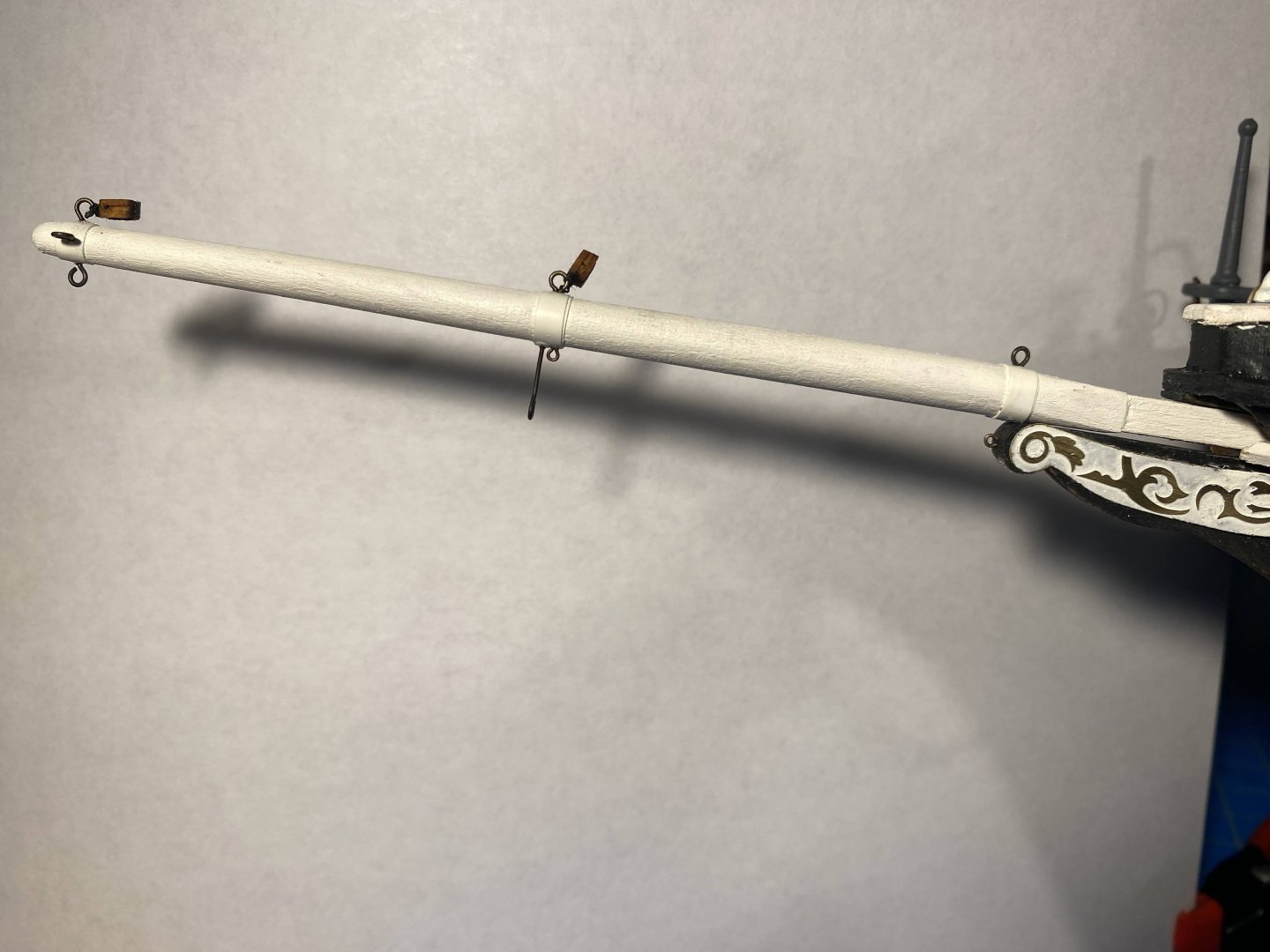
-
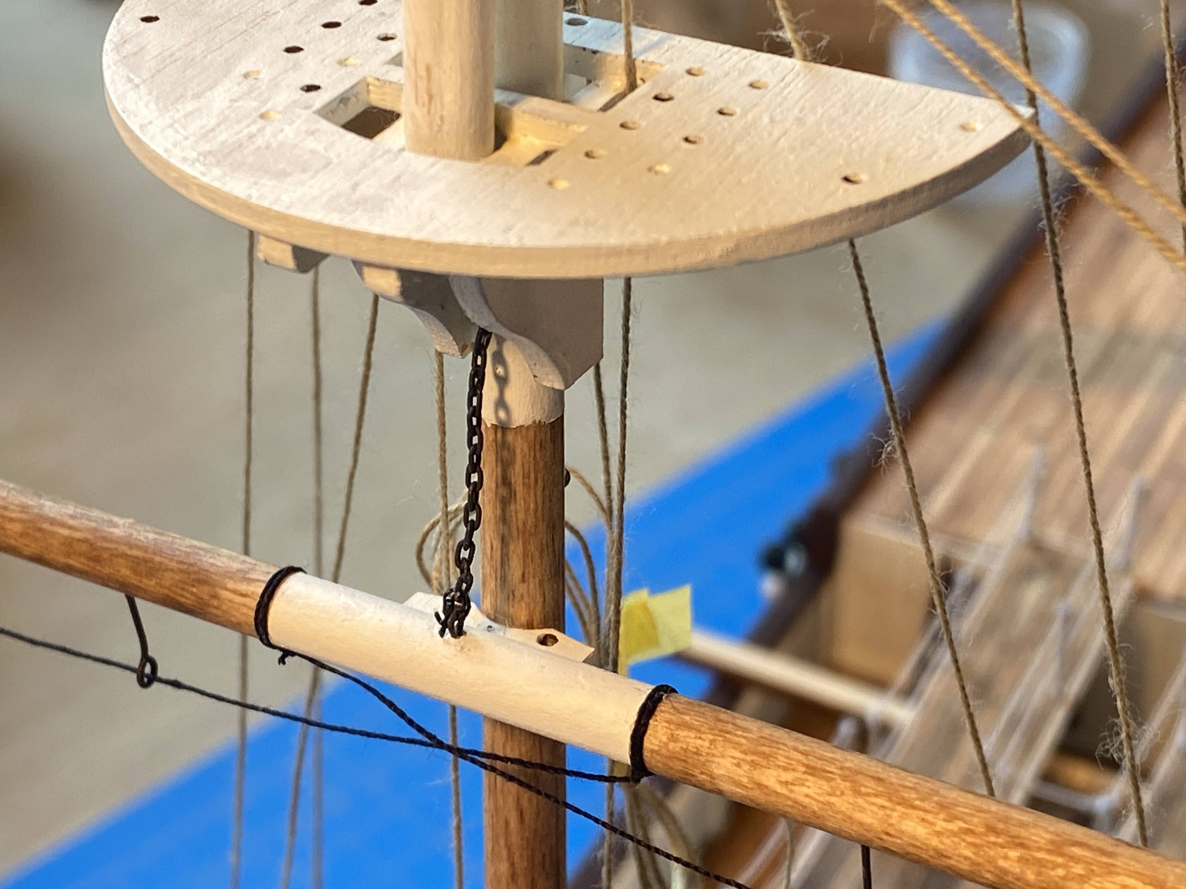
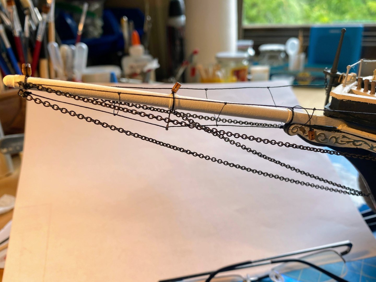
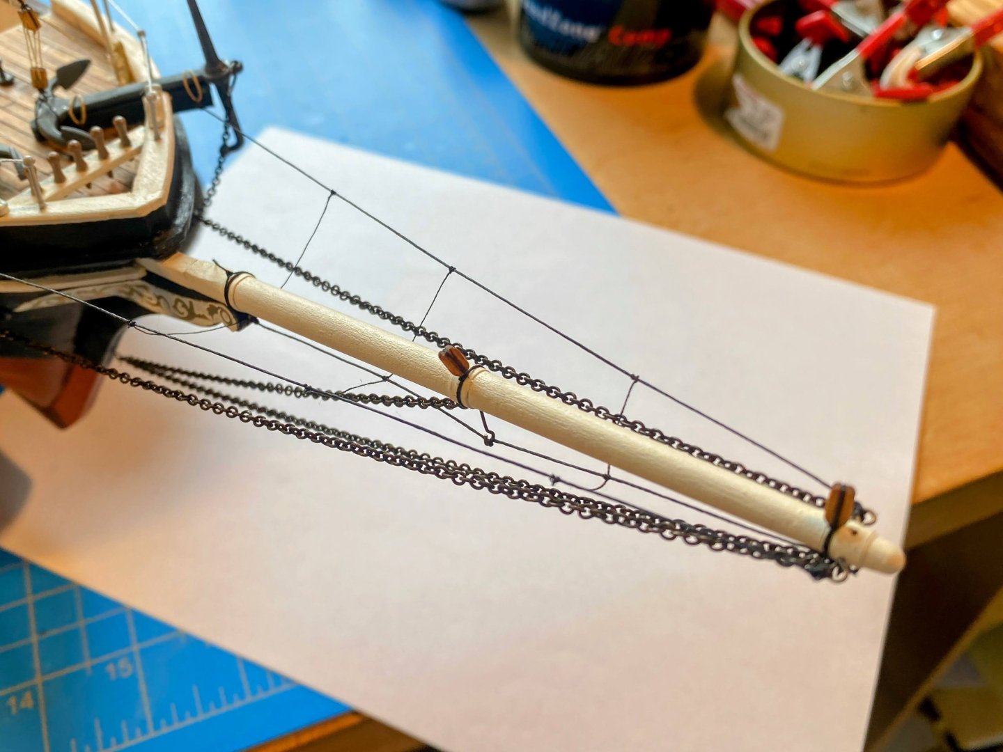
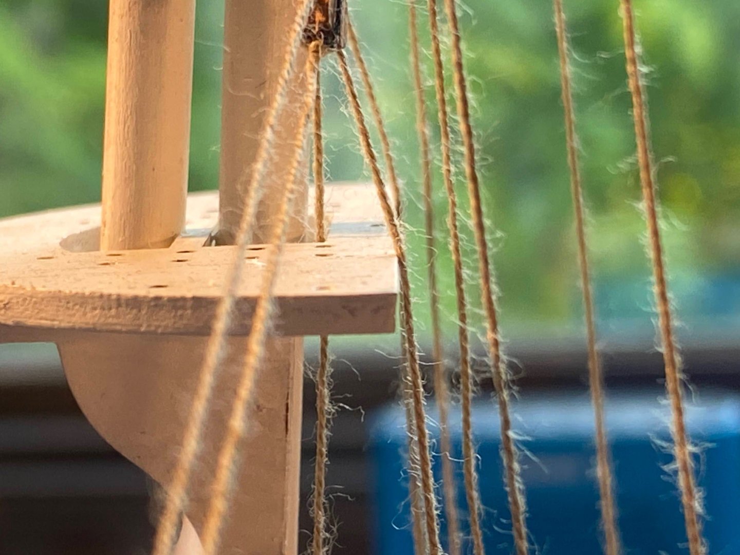
I have completed, glued in place and rigged the bowsprit. Other than blackening the chain (rather than leaving it bare brass), nothing worth commenting on that I can think of. In my last post I mentioned two things I wasn’t happy about: running rigging that rubs against structural pieces, and fuzzy rigging thread. The rigging that rubbed against the mast top was main spar lifts, and I have reduced (but not completely eliminated) that problem by running those lines down through holes OcCre drilled in the top. Those lines will now be secured on cleats at the base of the mast; previously they were to be secured on the pin rails at the bulwarks. As I mentioned in response to Gimp’s post, I have run about half of the installed running rigging through bee’s wax. That worked pretty well on a test piece of thread, but not as well on the installed rigging. You should be able to tell the difference in the pictures below (roughly the thread to the left in the pictures below have been waxed; the ones to the right have not). I know I should buy (or make my own) better thread, but the idea of completely redoing the rigging I’ve done on the foremast doesn’t excite me at all.

- 206 replies
-
- 4
-
-
- Endurance
- Shackleton
- (and 2 more)
-
Thanks for your kind words Chimp. It's been a fun build, and OcCre kits leave lots of room for some "kit bashing" (an unfortunate term, IMHO, but just about everyone on these boards knows what it means). I really like your Beagle. That kit is definitely among those I'm considering for a future build. If I do build it one day, I'll be reading your log carefully. Thanks for the rope walk suggestion. As a relatively quick break between this and my next build, I may do the NRG rigging project, which would be a perfect opportunity to learn to make my own rigging thread. What are you working on now?
-
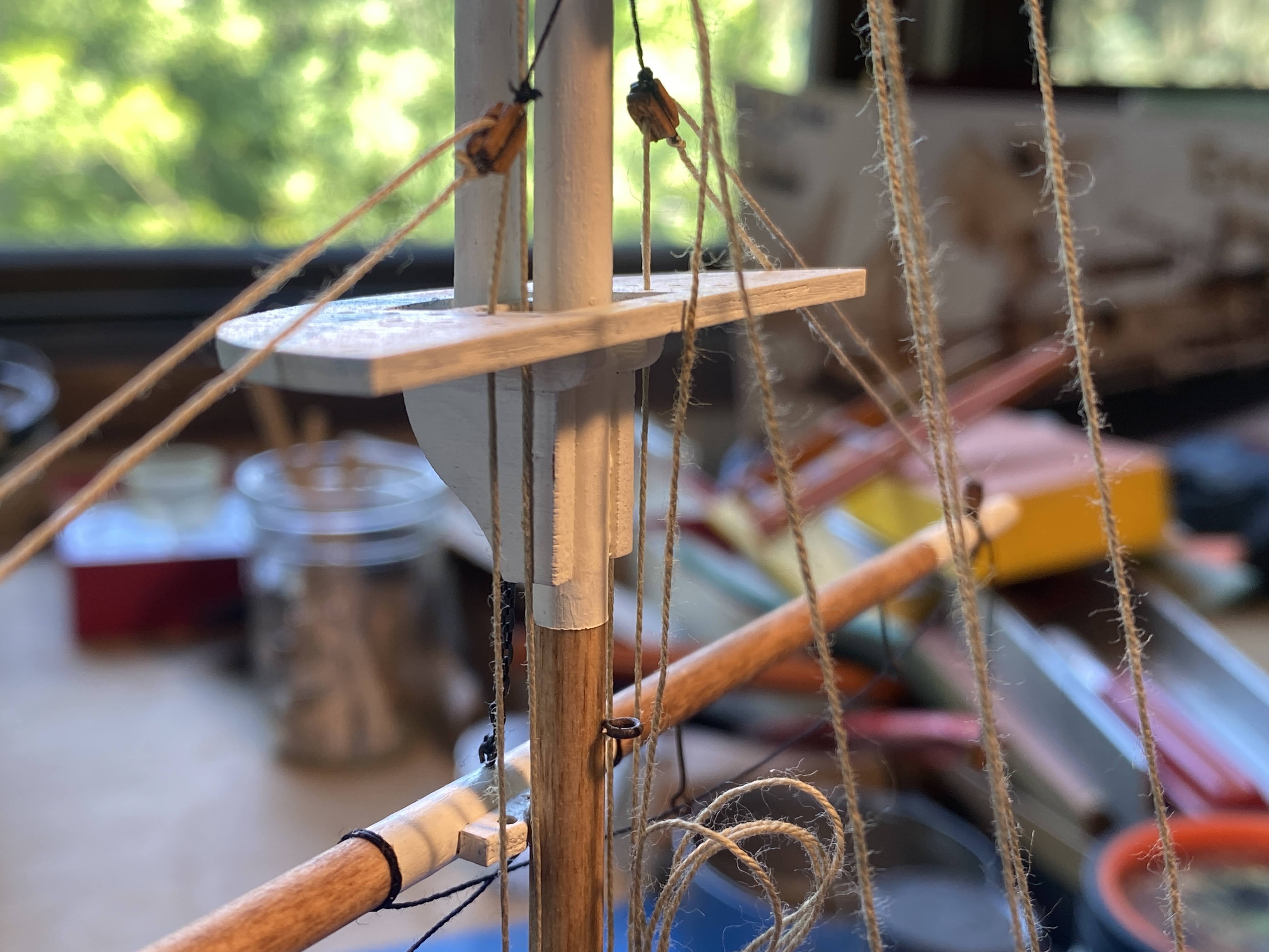
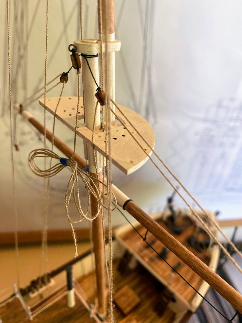
The yards have been glued to the mast and the running rigging is in place. Both the mast and the deckhouse are still loose fit; not ready to glue them yet. Similarly the working ends of the running rigging are not yet secured. The most difficult part of this was securing the chain sling to the eyebolt in the main yard. The eyebolt pulled out twice as I was trying to tie the chain to it. The last time I glued it back in place, I used thin CA glue, and some of it got on the chain, with the result that it is not quite straight. I managed to keep the swearing under my breath, so my better half wasn’t aware of my frustrations. 😀 I have not attached parrals (the collars that wrap around the back of the mast) to the yards yet. I added a block to the topsail yard so that there would be a double purchase on its halyard. Even the smaller yards are heavy, and I felt that a single purchase on that one would be inadequate. The same could probably be said about the topgallant yard. I haven’t put the gaff together yet, but I did hang some line off the stern of the mast cap for the gaff’s peak halyard. OcCre would have you also install a throat halyard, which makes no sense to me, since the gaff is attached to the mast with an immovable gooseneck. This is the case with all the ship’s gaffs. As I mentioned in my prior post, I’m trying to keep the rigging relatively simple, and not having throat halyards helps. I have not yet determined for sure where I want to fix the running rigging; that is, how to allocate it between the cleats at the base of the mast and the belaying pins on the bulwarks. I’m not paying much attention to how OcCre does it. In the photo below I have preliminarily fixed the yard halyards to the spider bands and the lifts to the belaying pins. When installed, the jib halyards will also be secured on the spiderband cleats. If my calculations are correct, the stick figure leaning against the deck house represents a crew member about 5’10” tall. One thing I want to avoid is running rigging that rubs against anything, as can be seen in the photo below. I have to figure out how to avoid that. That photo also shows how fuzzy OcCre’s rigging thread is. I have some bees wax which does a pretty good job of taking care of that problem. I forgot to use it, but I should be able to unrig the lines, apply some wax, and rerun them through the blocks.


- 206 replies
-
- 3
-
-
- Endurance
- Shackleton
- (and 2 more)
-
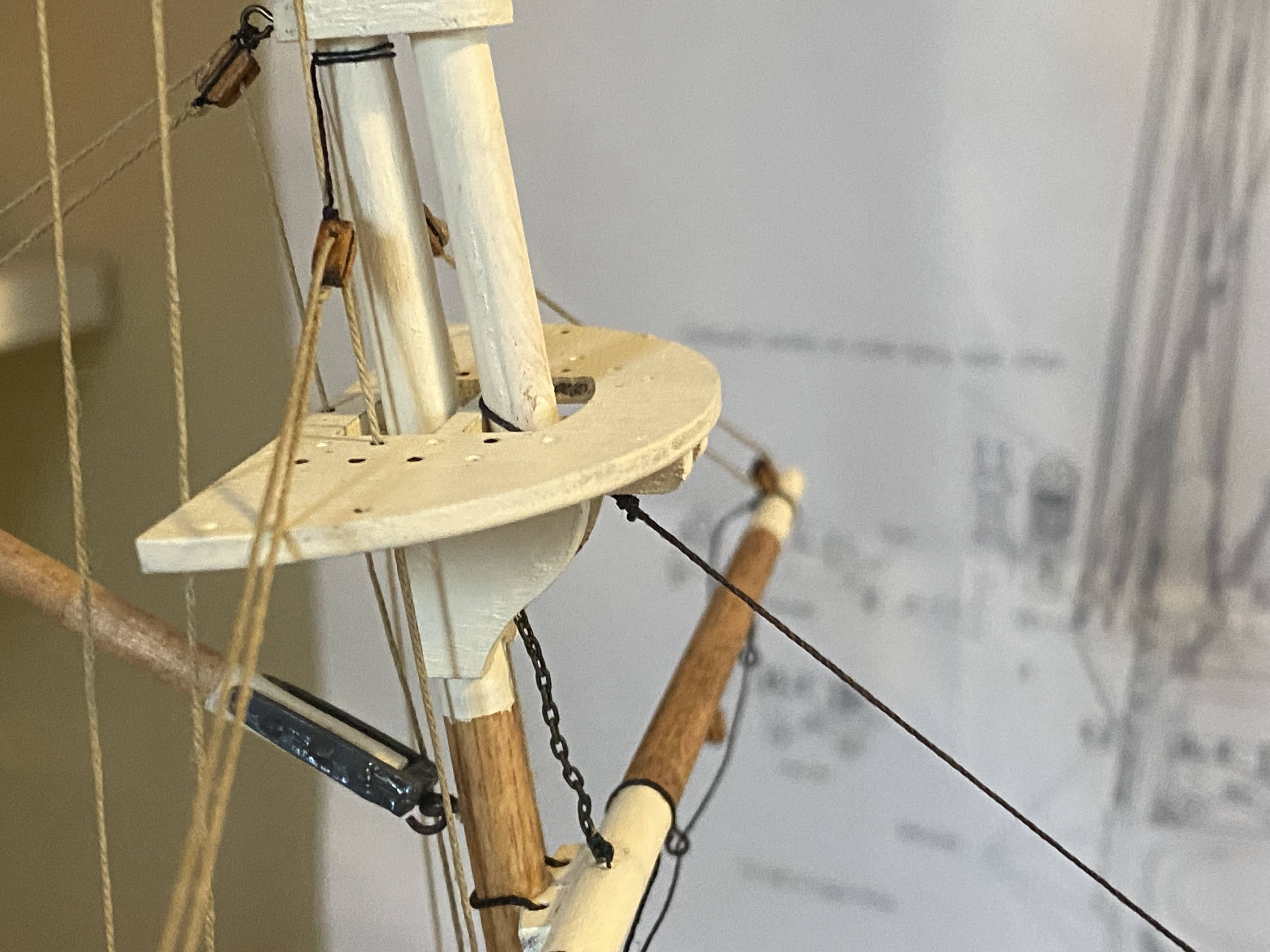
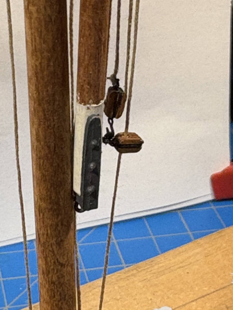
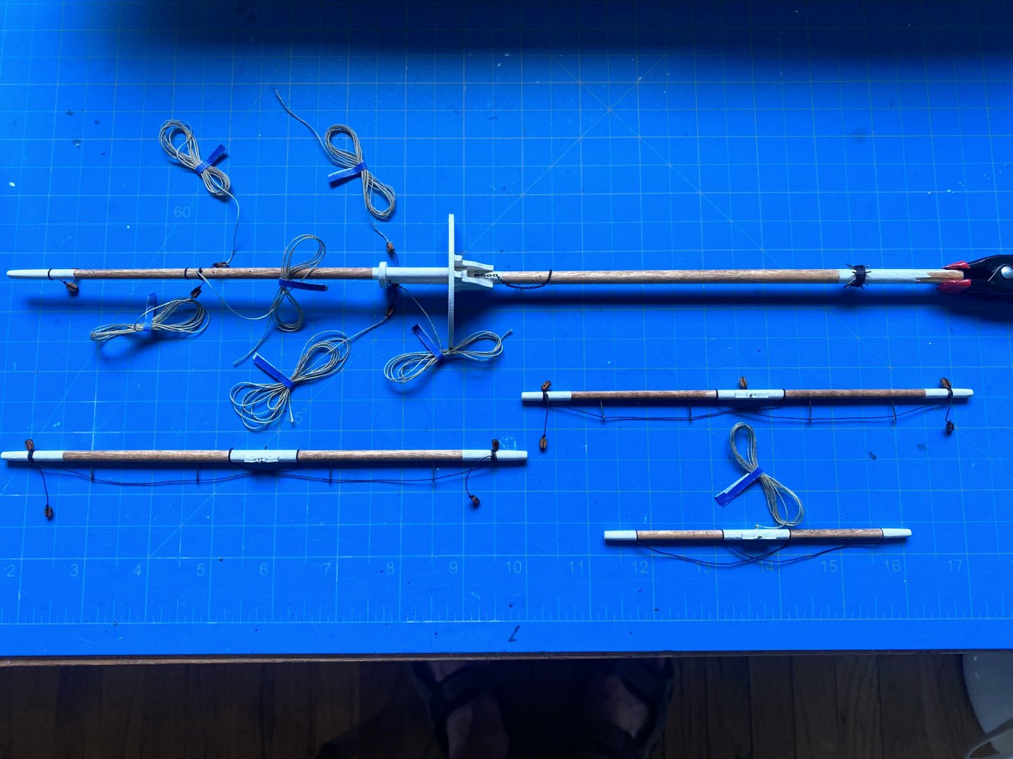
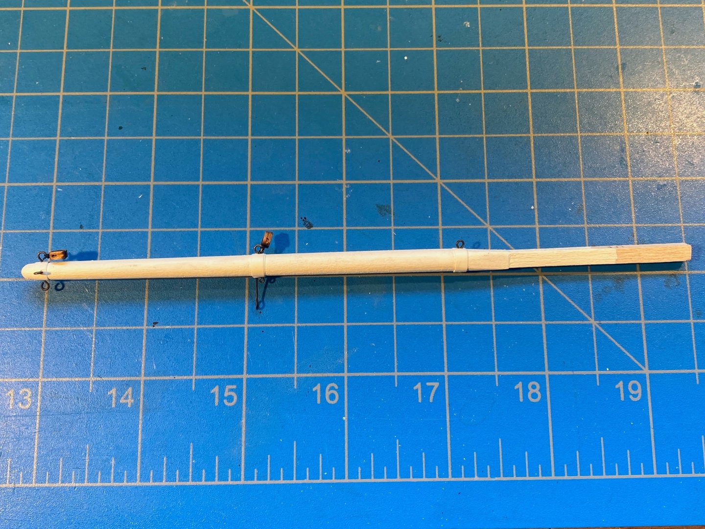
The foremast has three (instead of the more common four) yards: main (or course), topsail, and topgallant. If there were four, the highest one would be the royal yard. After cutting and tapering the yards, I chose not to paint them all white as OcCre does, but partially white, partially stained, as seen in the photos below. No authority I can cite for that; I just like the look better. You can see that I put a pin in each yard where it joins the mast (and drilled a corresponding hole in the mast) so as to attach the yard to the mast more securely. I then rigged footropes on all three yards, with jackstays on the main and topsail yards. Next step was attaching blocks and running rigging. A few general comments: Although OcCre has supplied them, I have decided not to put sails on my model. Personal preference. As a result, I decided to make the running rigging simpler, by not installing running rigging that is attached to the squaresails (as opposed to attached to the yards). So no sheets (lines running from the bottom corners of the sail [the clews] down to the deck) and no clewlines (running from those corners up to the yard the sail hangs from). I’m not crazy about the light color of the OcCre supplied blocks. I have quite a few darker blocks left over from prior builds, and I decided to use them instead. Also, they are slightly smaller than OcCre’s, which I think looks better. OcCre supplies a lot of beige colored 0.15m thread which I decided to use. Not bad quality, but not as nice as what’s available from Syren and other sources. I had thought about ordering some of the latter, but I hadn’t done it yet when I got to this stage of the build, and rather than wait for it to arrive, went ahead and used OcCre’s thread. Looking at the photo below, The topgallant yard has a halyard attached at the center. The topsail and main yards have blocks at each end for the yard lifts, and blocks with short lanyards at each end for the yard braces (fore and aft lines used to pivot the yard around the mast). The topsail yard also has a block in the middle for its halyard. Starting at the top, the mast has a pair of blocks for the topgallant yard lifts; a pair of blocks with lines attached for the topsail lifts and a block with line attached for its halyard; and a pair of blocks with lines attached for the main yard lifts, a chain for the main sling (no halyard), and a block with line attached at the back of the cap for the gaff peak halyard. Now I just have to put it all together.

- 206 replies
-
- 2
-
-
- Endurance
- Shackleton
- (and 2 more)
-
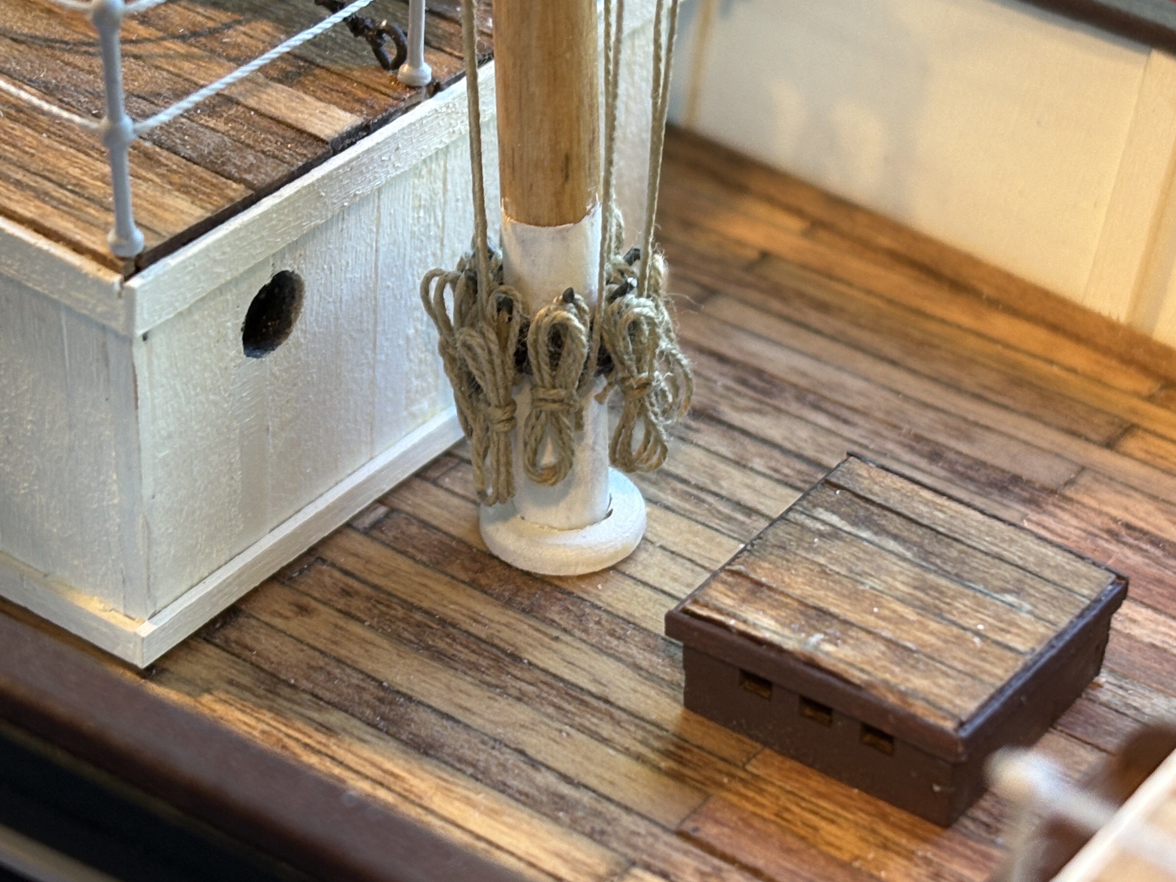
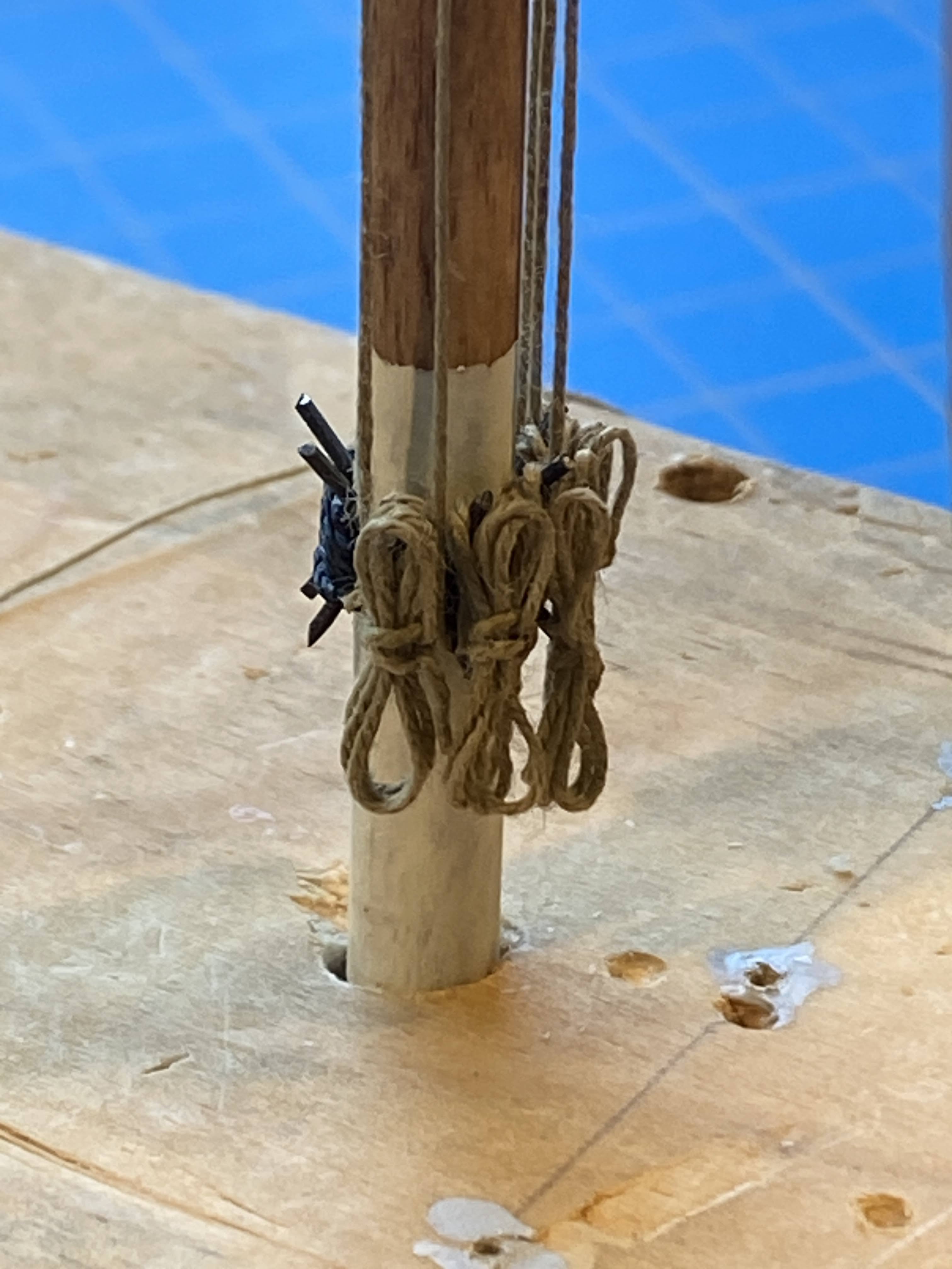
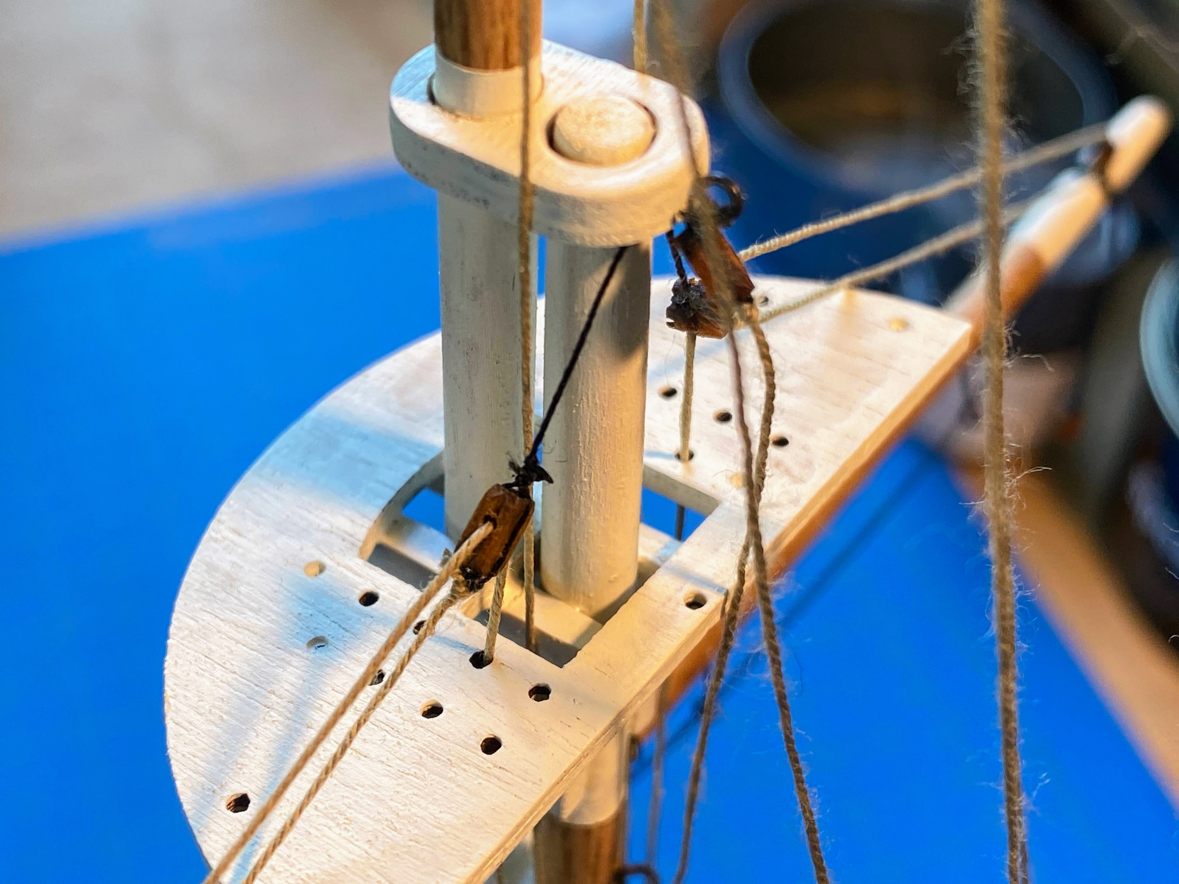
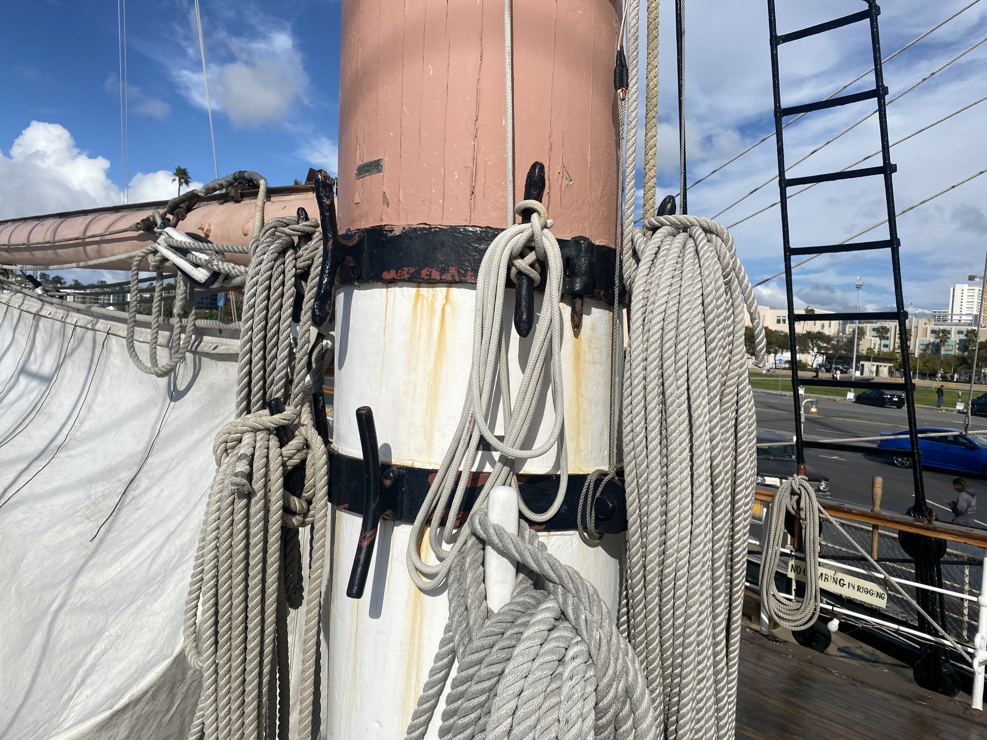
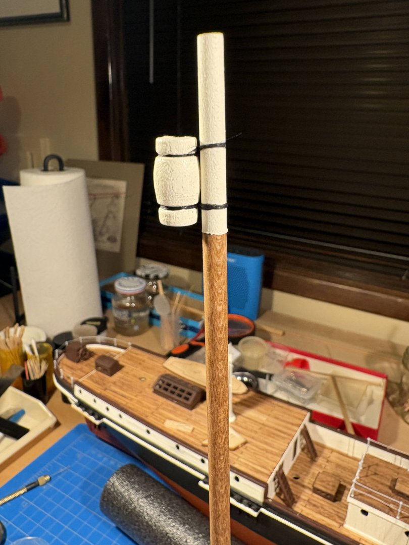
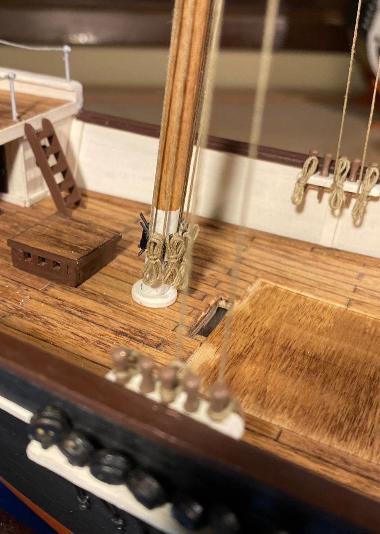
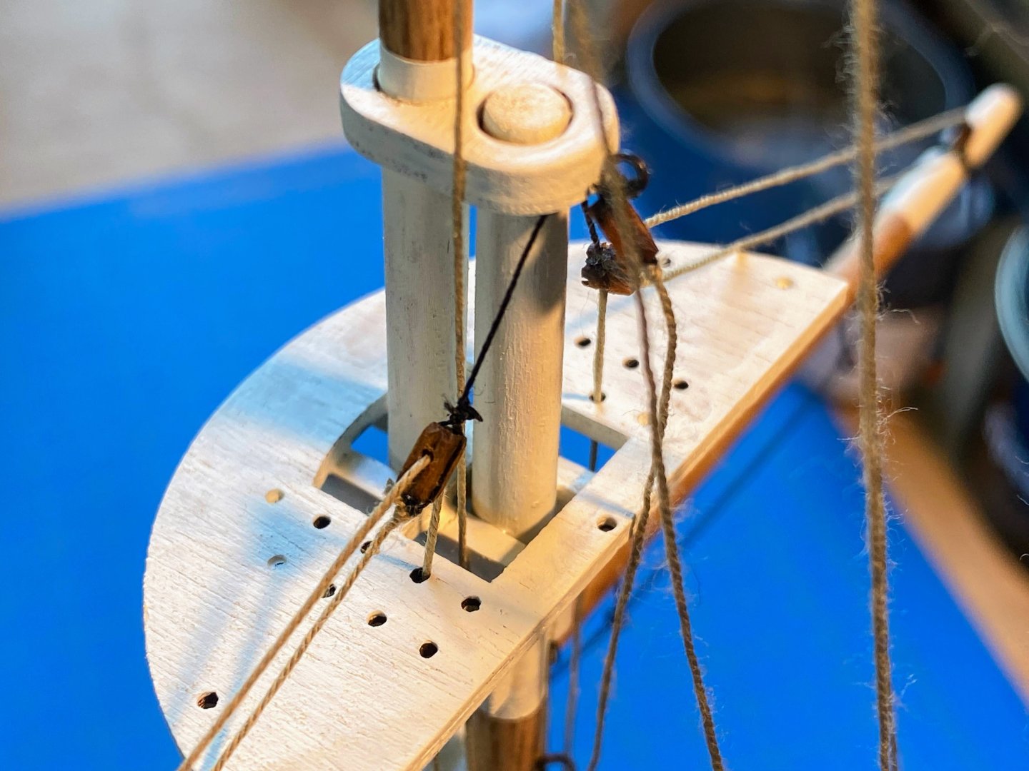
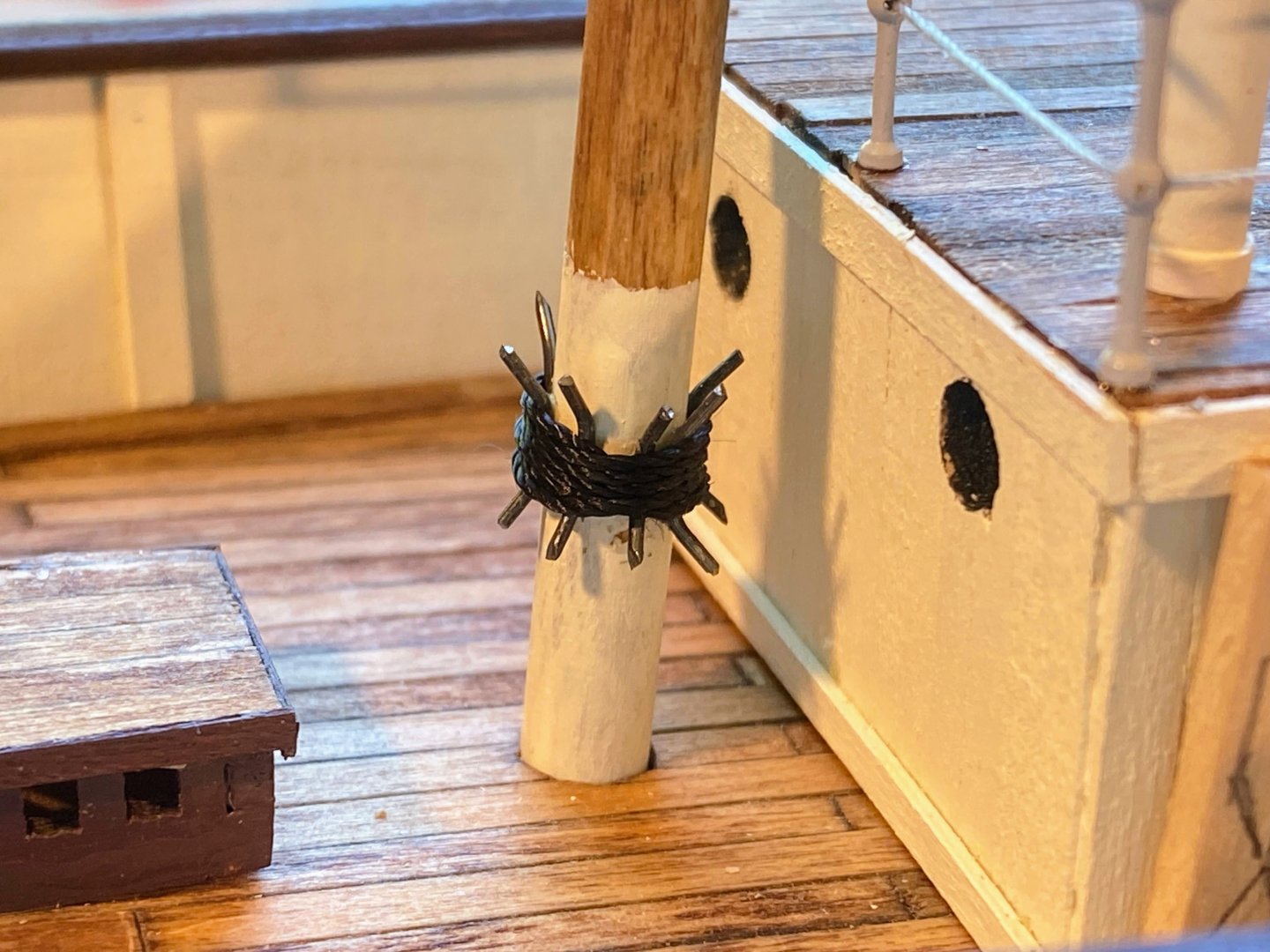
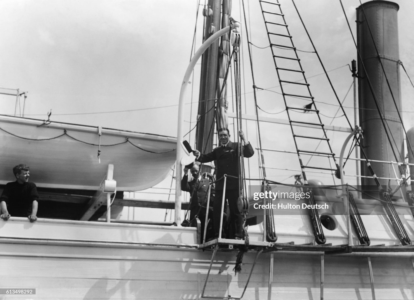
I decided to work on the foremast next. The basic assembly and painting was pretty straightforward . . . ….. with one exception. There was a discussion some months ago about how the loose end of the running rigging was secured near the base of the mast. There was general agreement that tying the lines to eyebolts in the deck, as OcCre would have you do it, was not realistic. Once the original ship was discovered a couple of years ago, a photo surfaced which showed a pin rail ring around one of the masts. You have to look carefully to see it in the first picture below. I was concerned that if I tried to fabricate something like that, the model’s too-fat belaying pins would make the whole thing stick out too far from the surface of the mast to look right. Earlier this year I had the good fortune to pay a visit to San Diego’s wonderful maritime museum. The second photo is of a spider band around one of the masts of the clipper ship Star of India, which is birthed there. I thought maybe I could duplicate that, and even if it is not quite authentic, the bulk of it would be hidden by rope coils, and the end result might look pretty good. I bent some wire to make cleats, glued the cleats to the mast using wood glue, wrapped some medium thick thread around them, and doused the thread with white school glue to better secure everything. It looks a little ugly now, but should look much better when rope coils are added.


- 206 replies
-
- 5
-
-
- Endurance
- Shackleton
- (and 2 more)
-
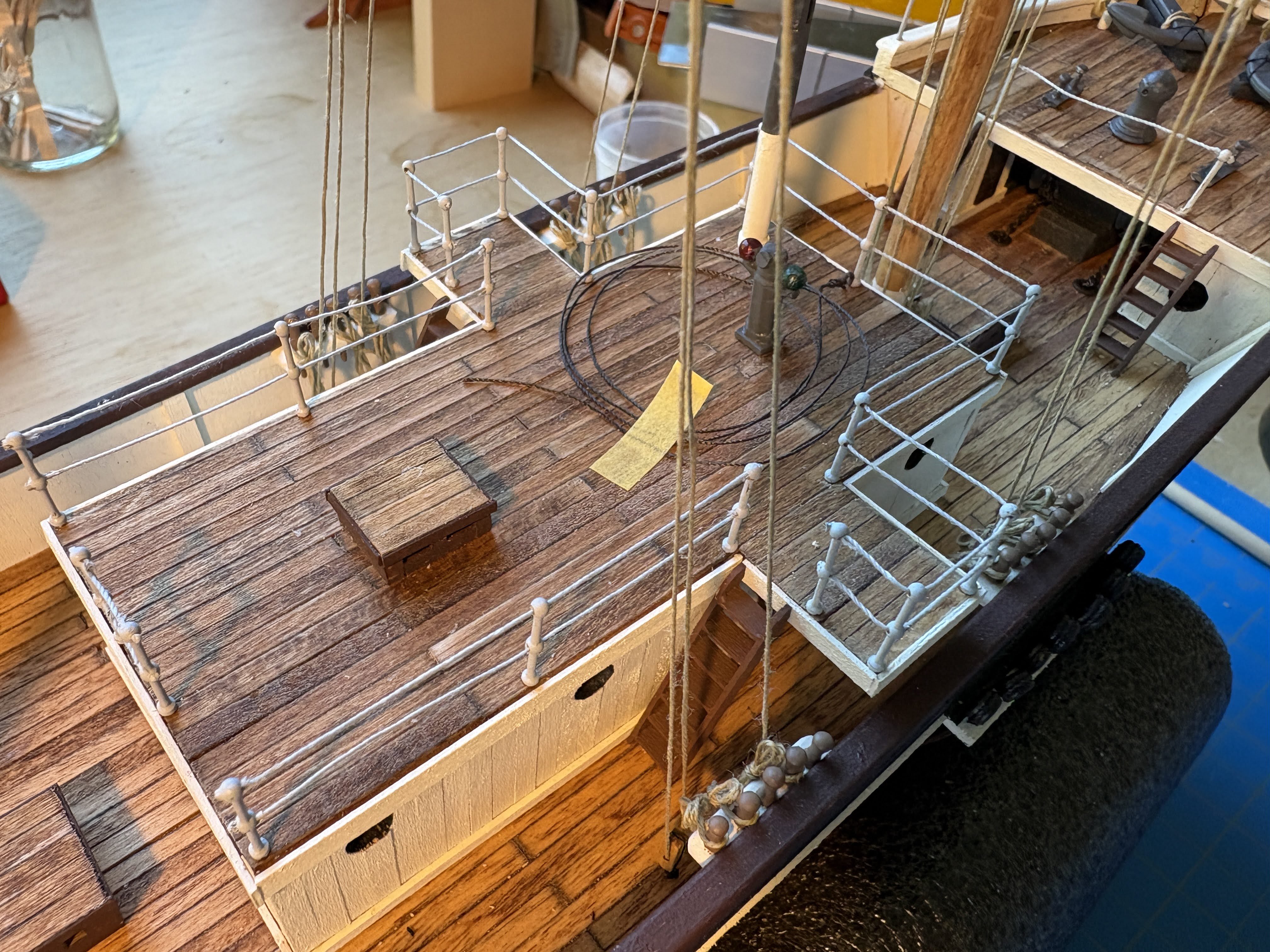
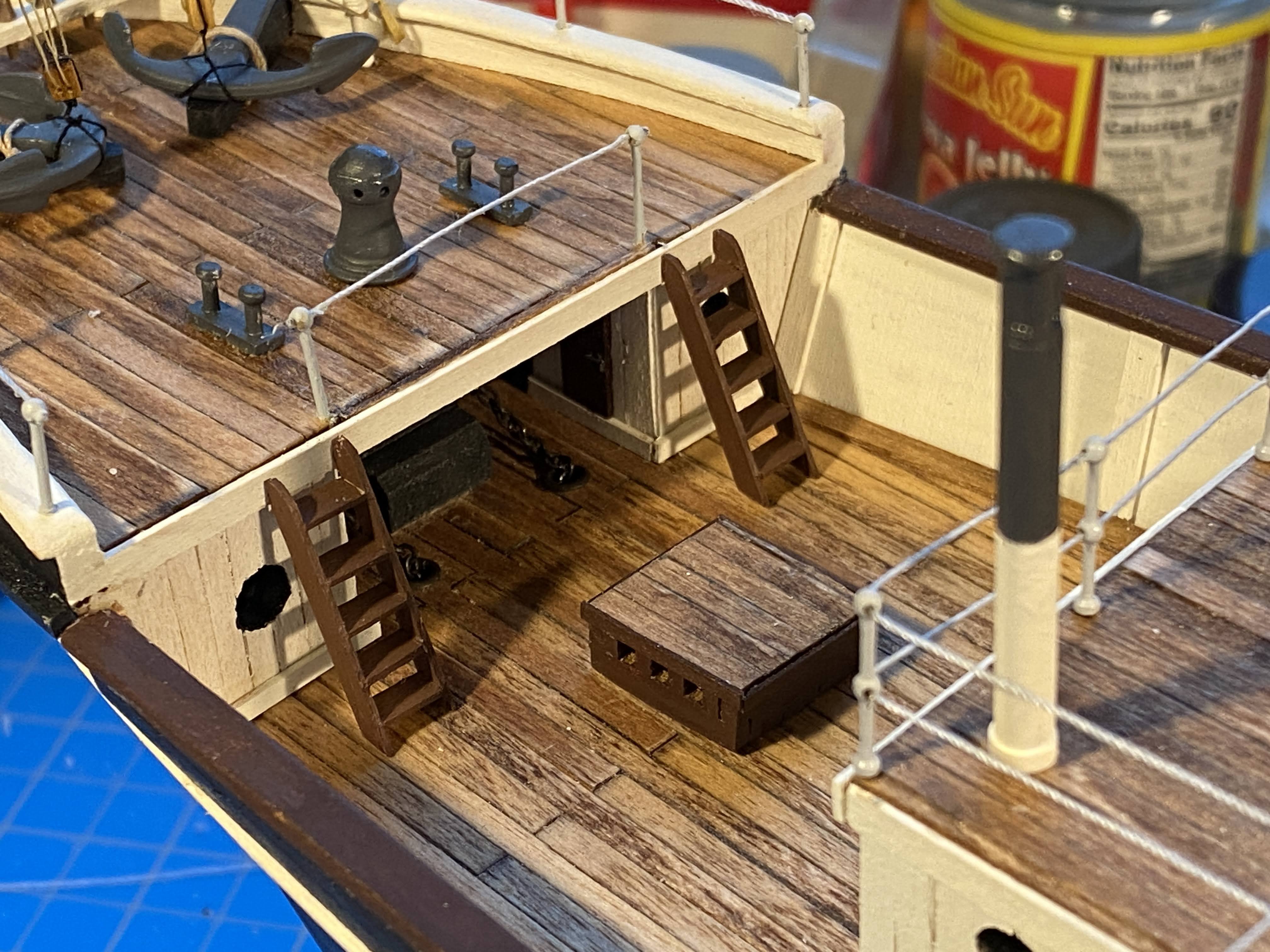
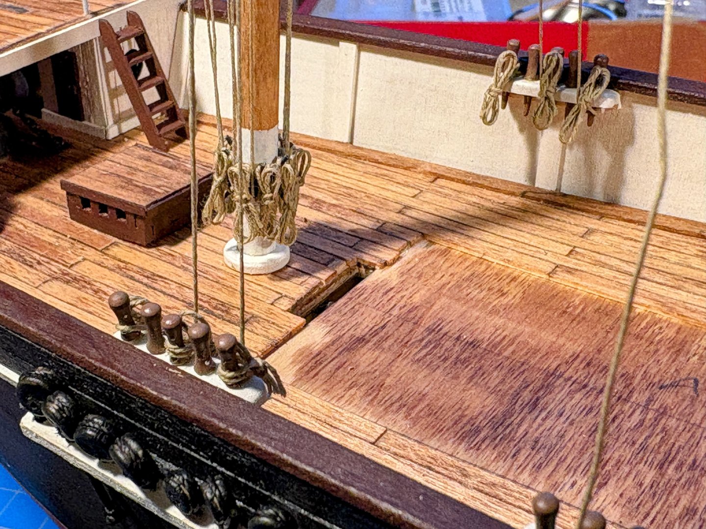
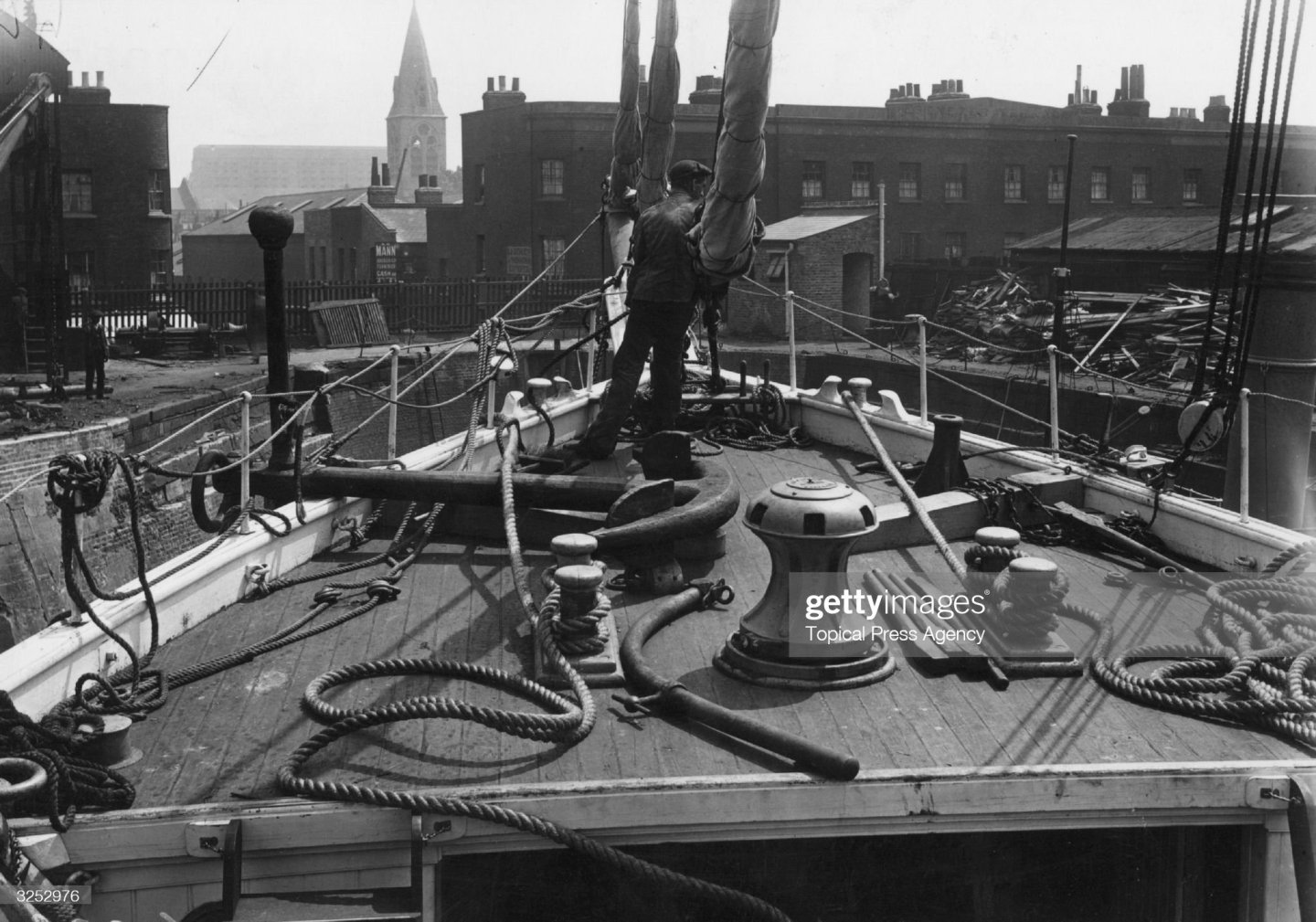
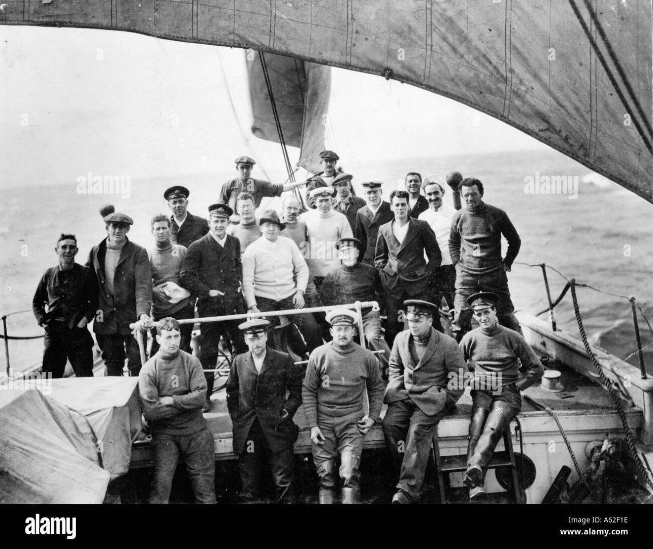
Anchor deck and aft deck stanchions and railings completed. With regard to the anchor deck, as you can see below, there are photos out there that both show a railing running between the two ladders and show no railing there. The latter railing must have been added later in the voyage. I opted to put that railing in. Obviously the no-railing photo was taken in a port, but I have no idea where. The stanchions for the aft railing are closer together than the other ones, in order to maintain the curve around the stern. After completing the aft railings I noticed a big mistake I made. There is a wooden cap that is the top of that railing, which I had seen but forgot about. I simply did what OcCre did. Whether I go back and redo it remains to be seen, but if it happens, it won’t be anytime soon. I am delaying working on the railings for the deck immediately forward of the aft deck. I need to think about the order in which I install the shrouds and ratlines, the dog kennels and those stanchions and railings. One will likely get in the way of the other, and the railings are fragile, susceptible of being snagged when I’m tying the ratlines, for instance.


- 206 replies
-
- 2
-
-
- Endurance
- Shackleton
- (and 2 more)
-
Thank you George. I just now looked at your Discovery and Kearsarge builds, which are coming along nicely. I don't know how I'd find the time to do two simultaneously.
-
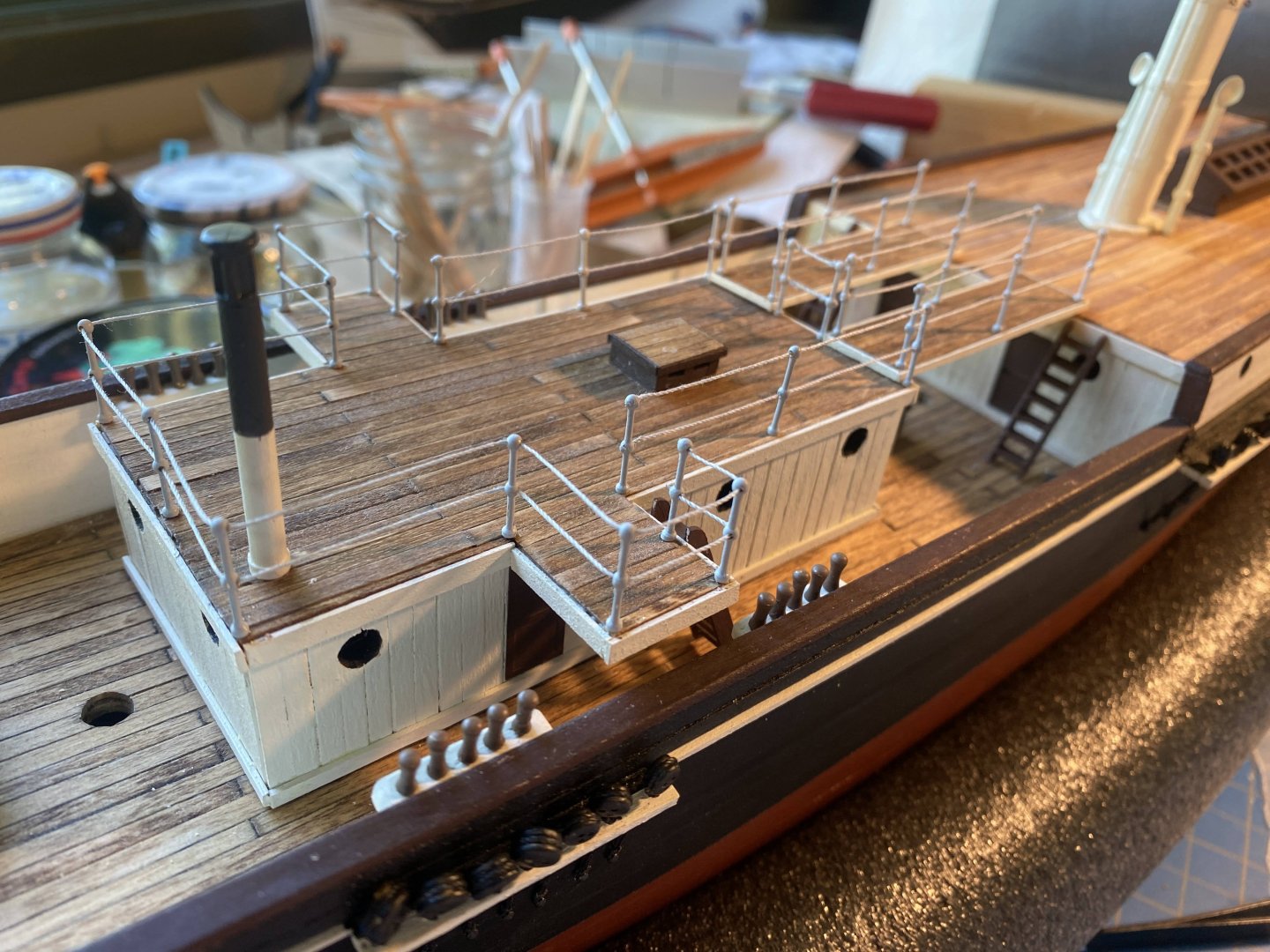
Deckhouse stanchions and railings completed. OcCre has the stanchions placed quite a bit closer together generally than they are spaced on the planks between the deckhouse and the deck behind it. I decided to space the rest of the stanchions as they are on those planks, about 31 mm apart. I just thought that looked better. On those planks I tried to cut off the loose ends using scissors, and I wasn’t very pleased with the result. On the deckhouse, I used (gently) a brand new X-acto blade with much better results. Deckhouse, planks and stairs are still only dry fit. I don't see how rigging could be secured to the lower part of the mainmast with those things glued in place.
- 206 replies
-
- 4
-
-
- Endurance
- Shackleton
- (and 2 more)
-
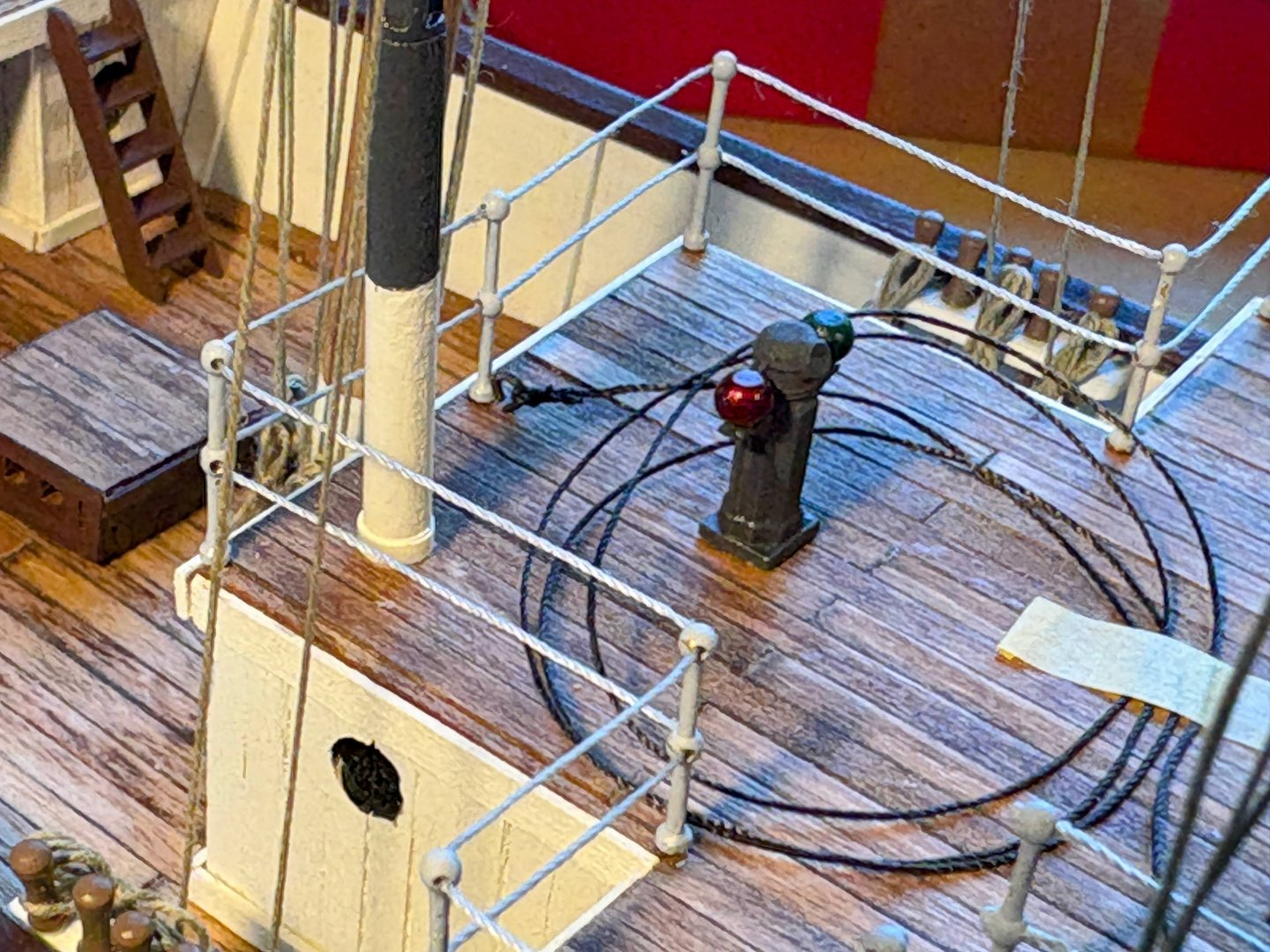
Thank you SHJ. I always appreciate your comments. As I look at the Hurley photos, it appears that the railings between the stanchions are sometimes wire cable and sometimes a fixed rod or bar. By using thread, I’m choosing to simulate cable throughout. Thus the railings at the bow and stern will run straight between stanchions and will not match the curve of the hull at deck level. Not so obvious at the bow, but will probably be noticeable at the stern. But I can live with that.
-
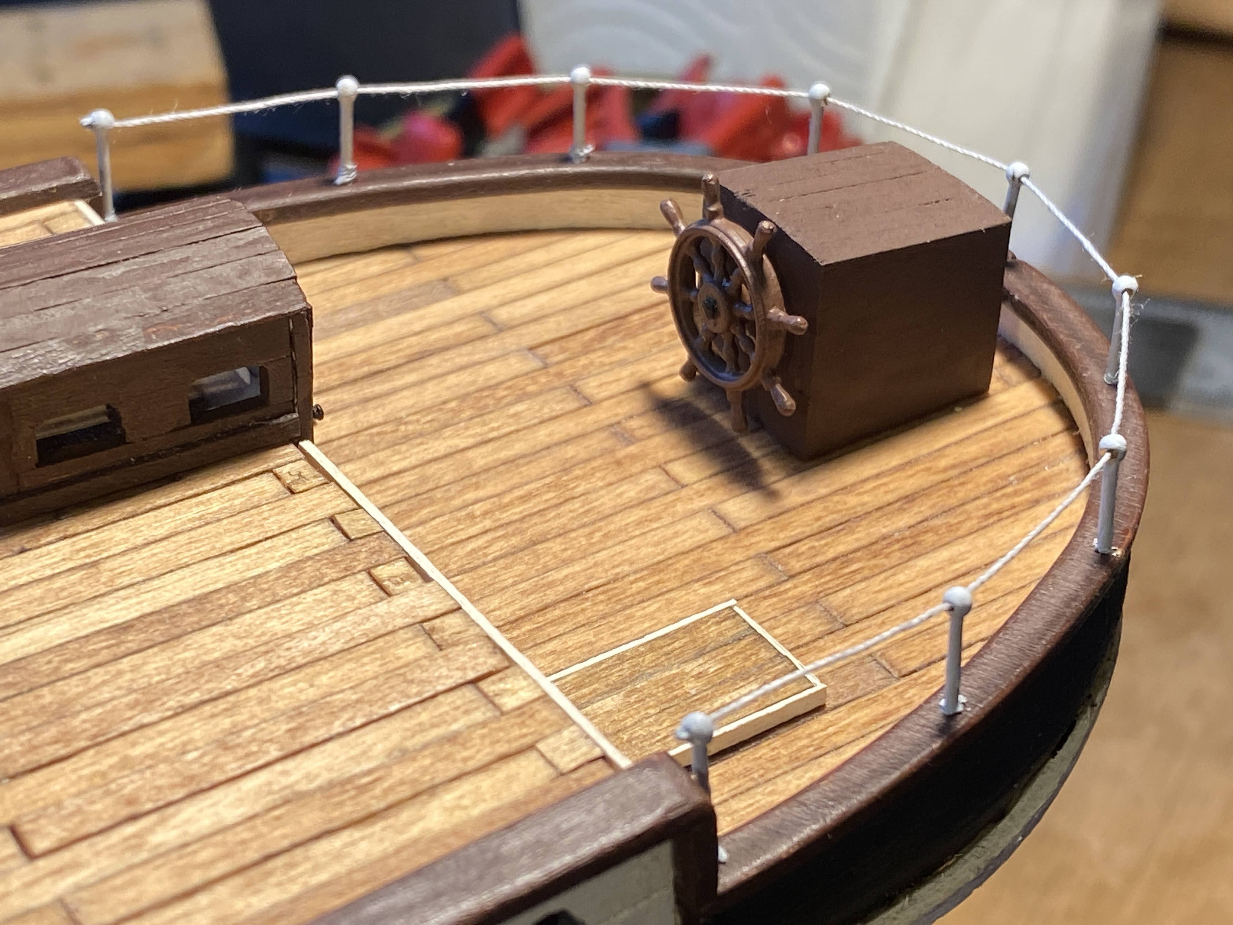
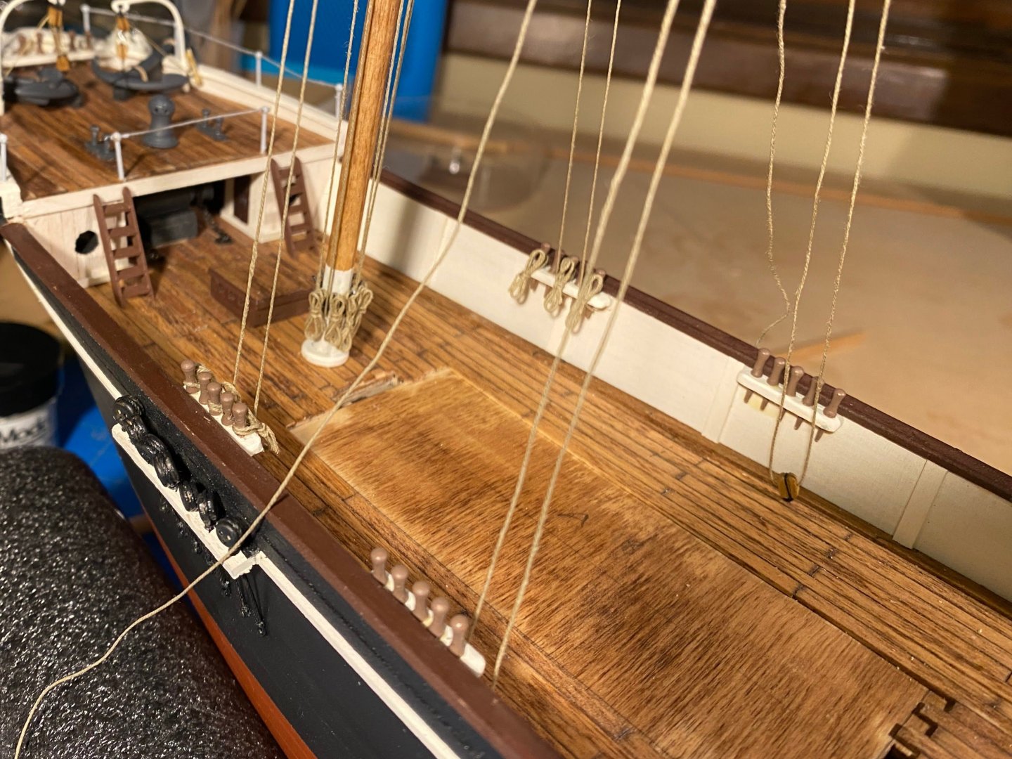
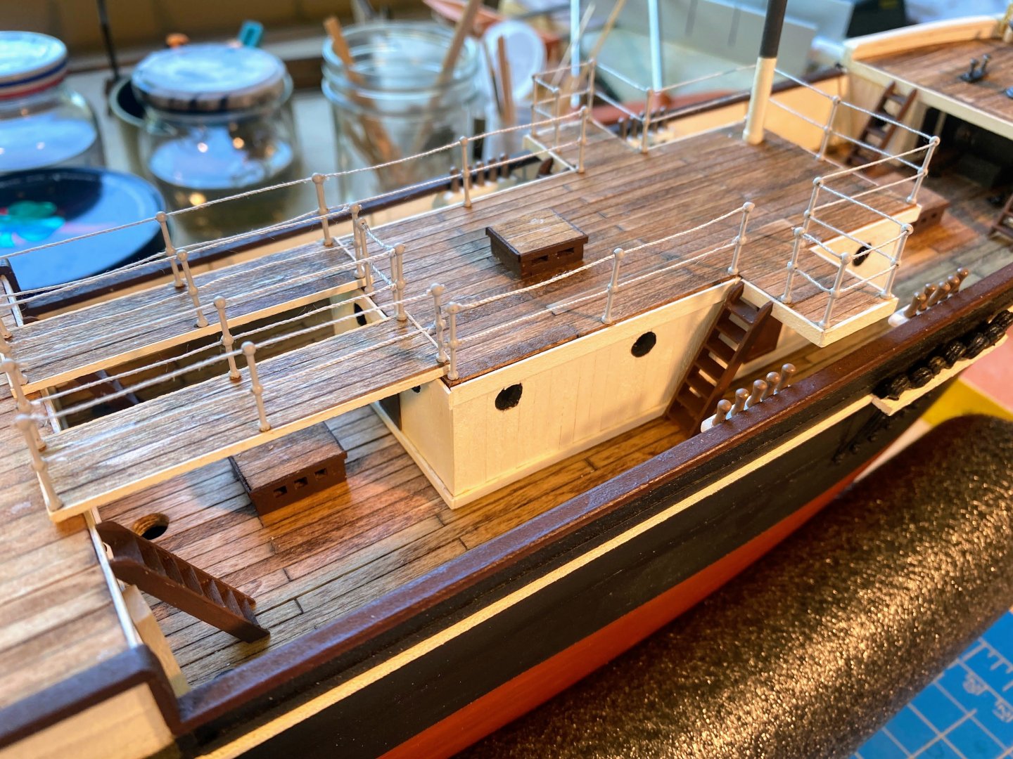
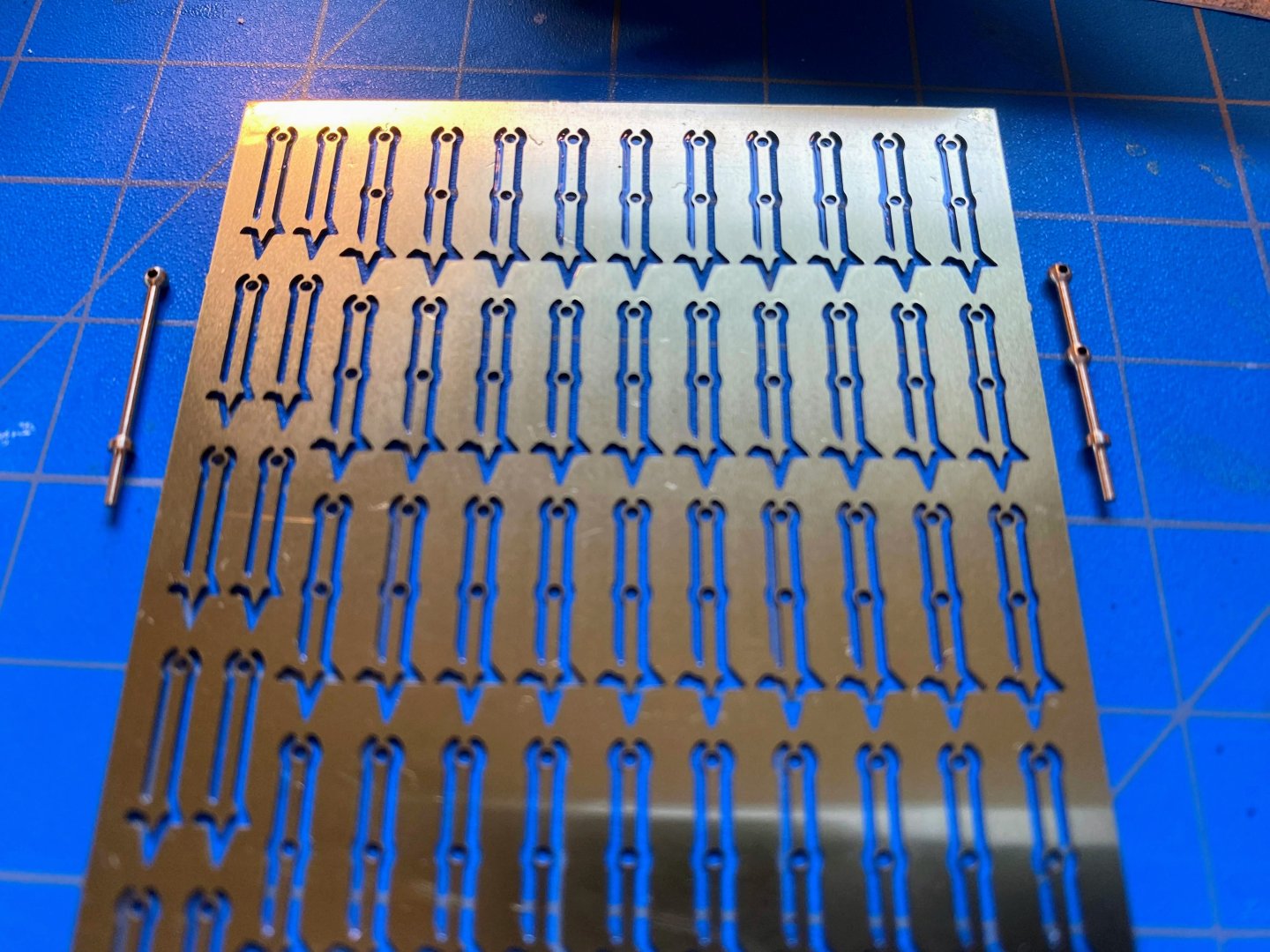
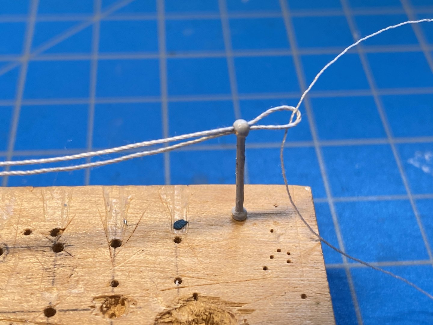
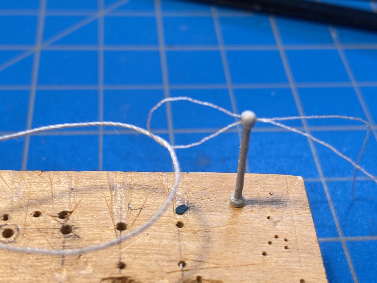
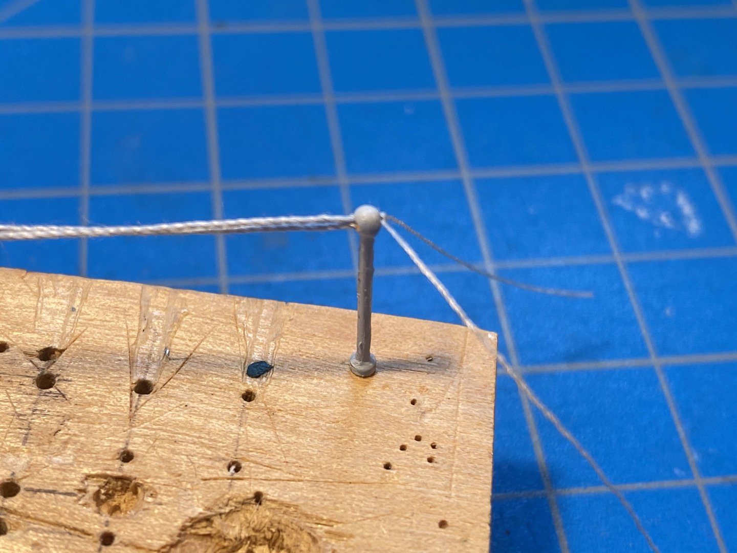
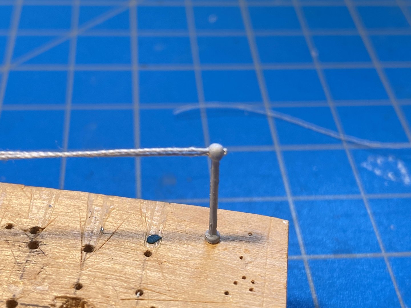
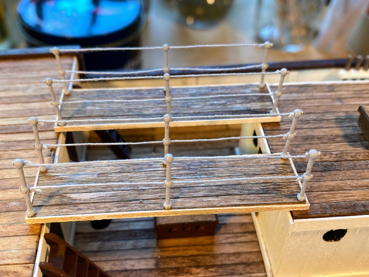
It’s been almost a month since I last posted. Summer weather (no heat dome here yet) and other interests have slowed down work in the shipyard. I finished the channels, deadeyes and chainstays on the starboard side. Pretty much like the port side, but I learned how to do it a little bit more efficiently. Stanchions up next. Comments: As many others have done, I purchased brass stanchions which look a lot more realistic than the photo etched ones furnished by OcCre. I got them from Cromwell Model Boats in the UK. Cost and time to ship to the US were quite reasonable. Both one and two hole stanchions are 15mm above the deck, which is 3mm and 5mm taller (2 hole and 1 hole respectively) than OcCre’s stanchions. The difference is acceptable (at least to my eyes) as to the 2 hole stanchions and can be remedied by cutting the base and mounting pin off the 1 hole stanchions. For whatever reason, to me the stanchions look more realistic if they aren’t bright white, and I mixed up some light gray paint to use instead. To each their own I guess. Similarly I used gray thread for the cables running between stanchions. I used a loop of thin thread to pull a loop of the thicker thread through the hole in the stanchion, then with the thin thread in place, pulled the thicker thread taut, and pulled the thinner thread clear leaving a tiny bit of the thicker thread’s loop showing. I sealed the deal (I hope) with a drop of diluted white school glue. Finally, after trimming the loose ends, I added a drop of light gray paint to the slightly exposed part of the thicker thread’s loop. These pictures should be clearer than what I just wrote. . . I started with the planks running between the deck house and the deck behind it. This close up makes the trimmed ends much more evident than they are from a normal viewing distance. The deck house will be next.
- 206 replies
-
- 3
-
-
-
- Endurance
- Shackleton
- (and 2 more)
-
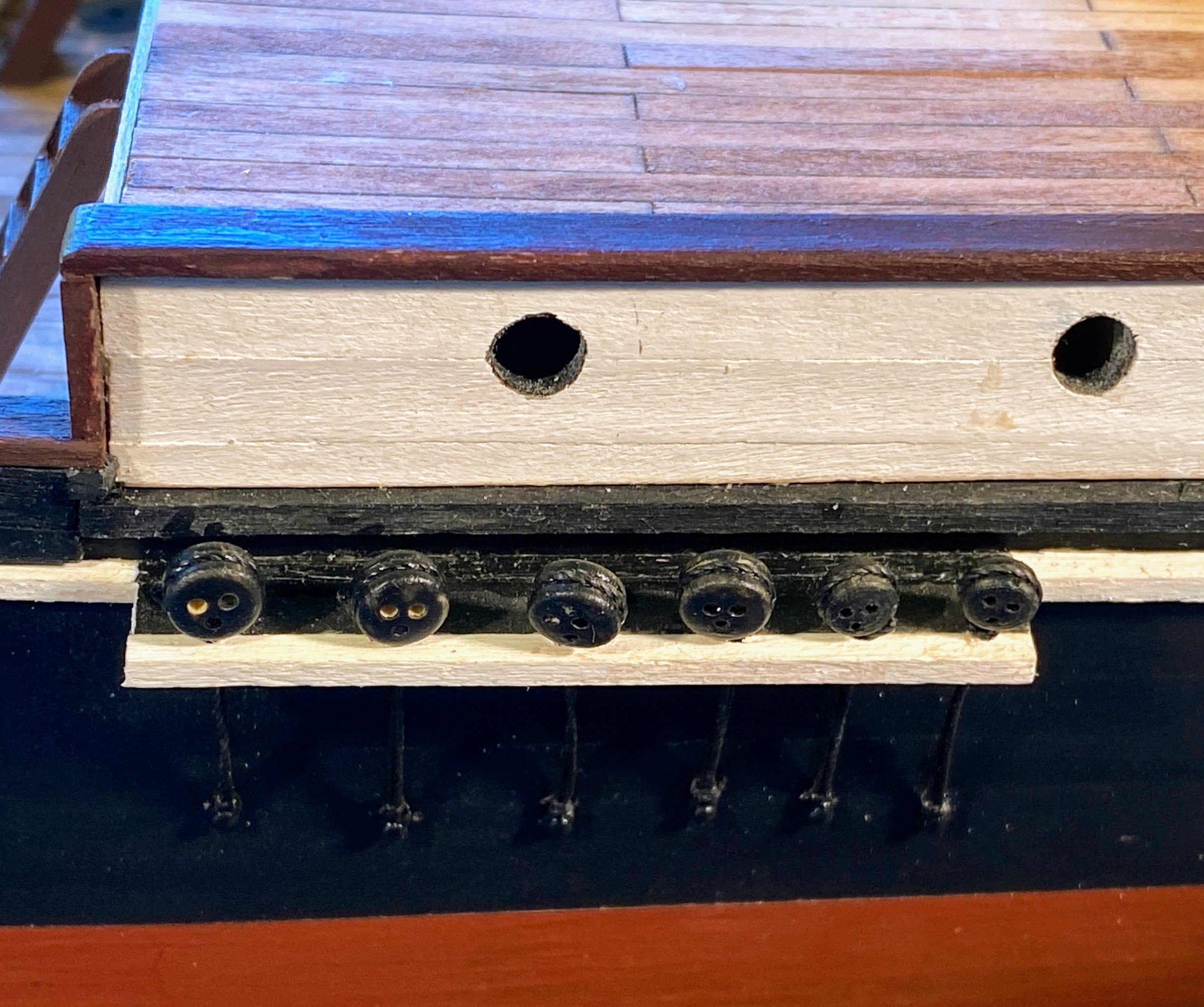
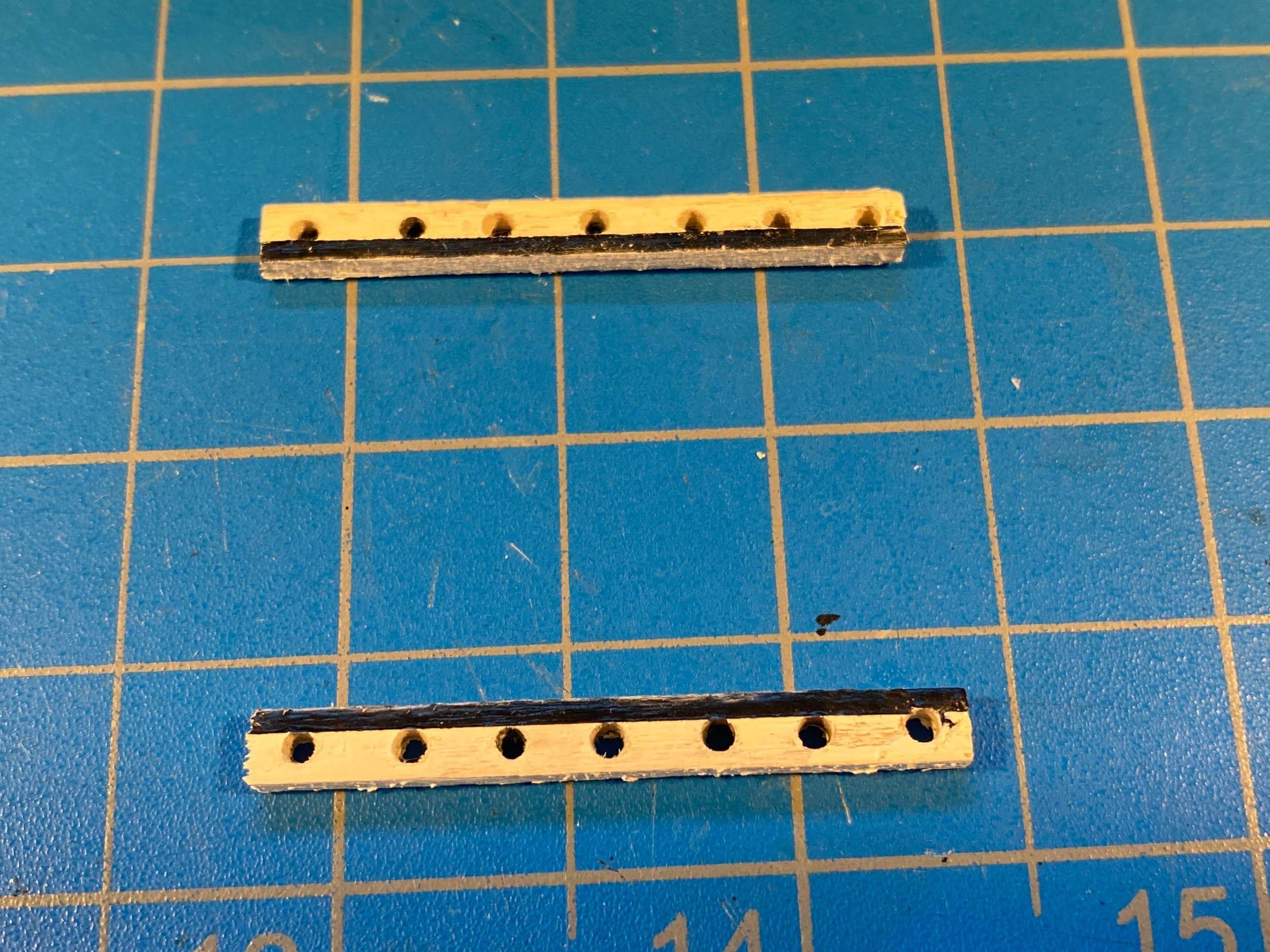
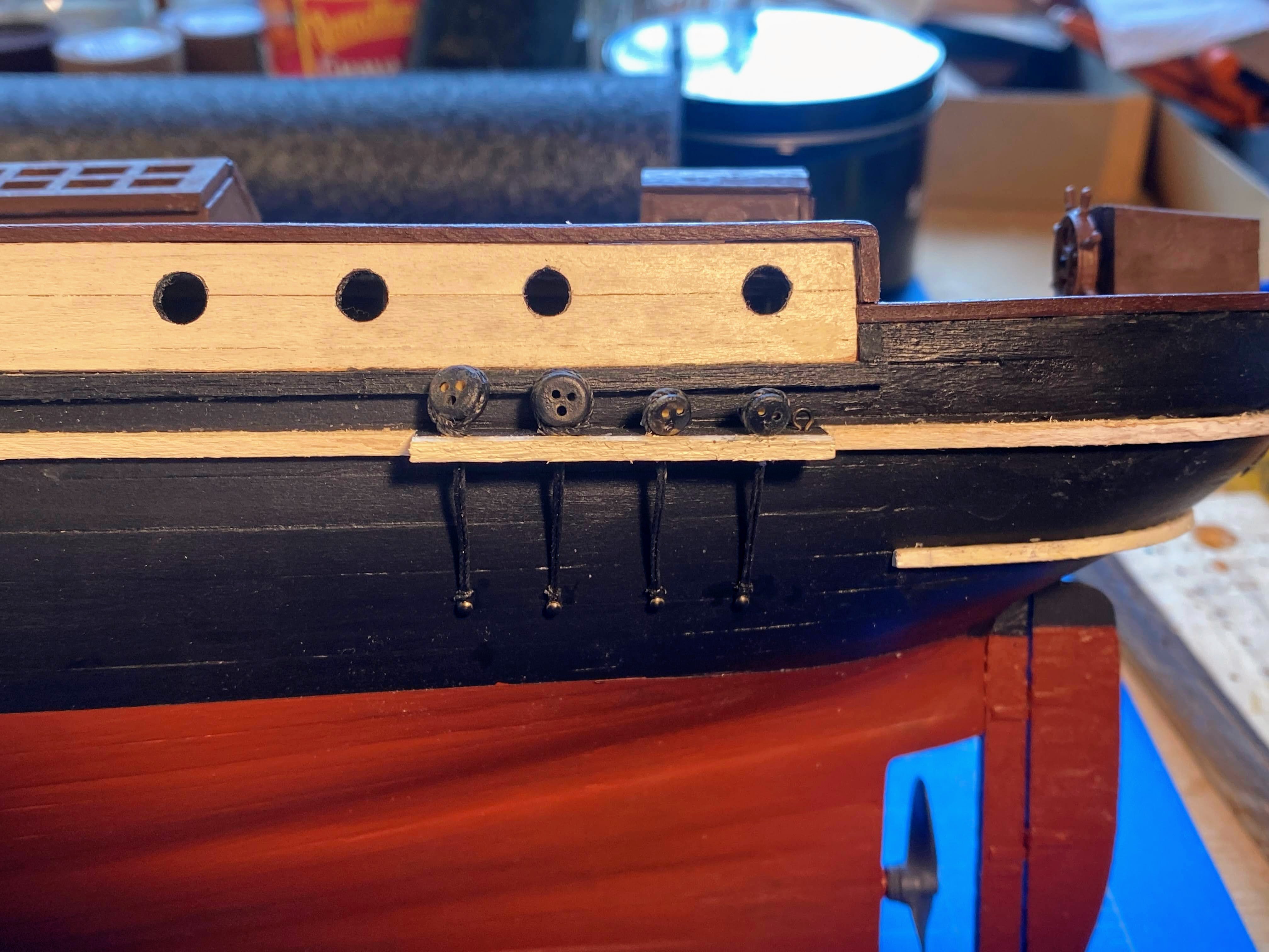
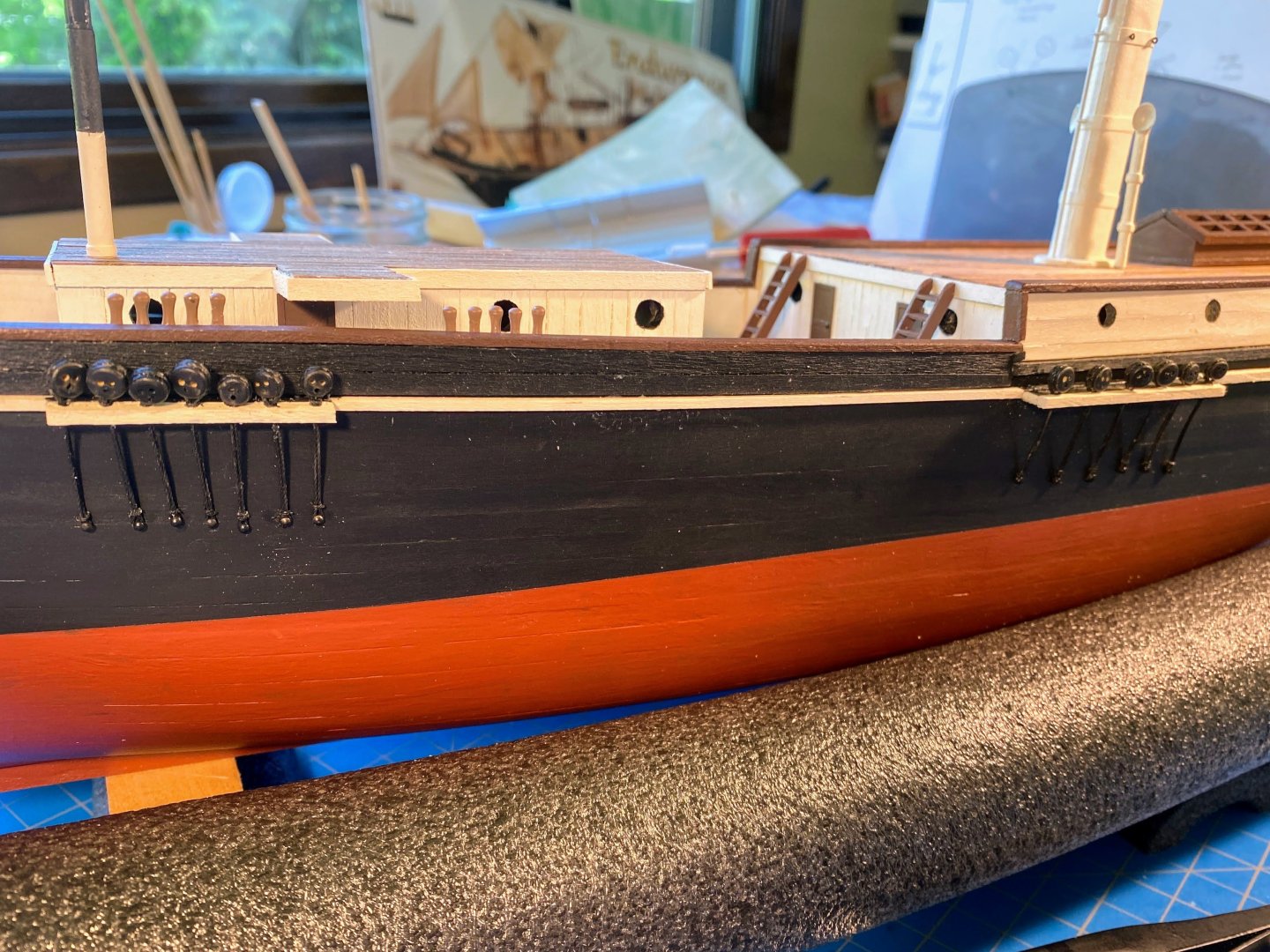
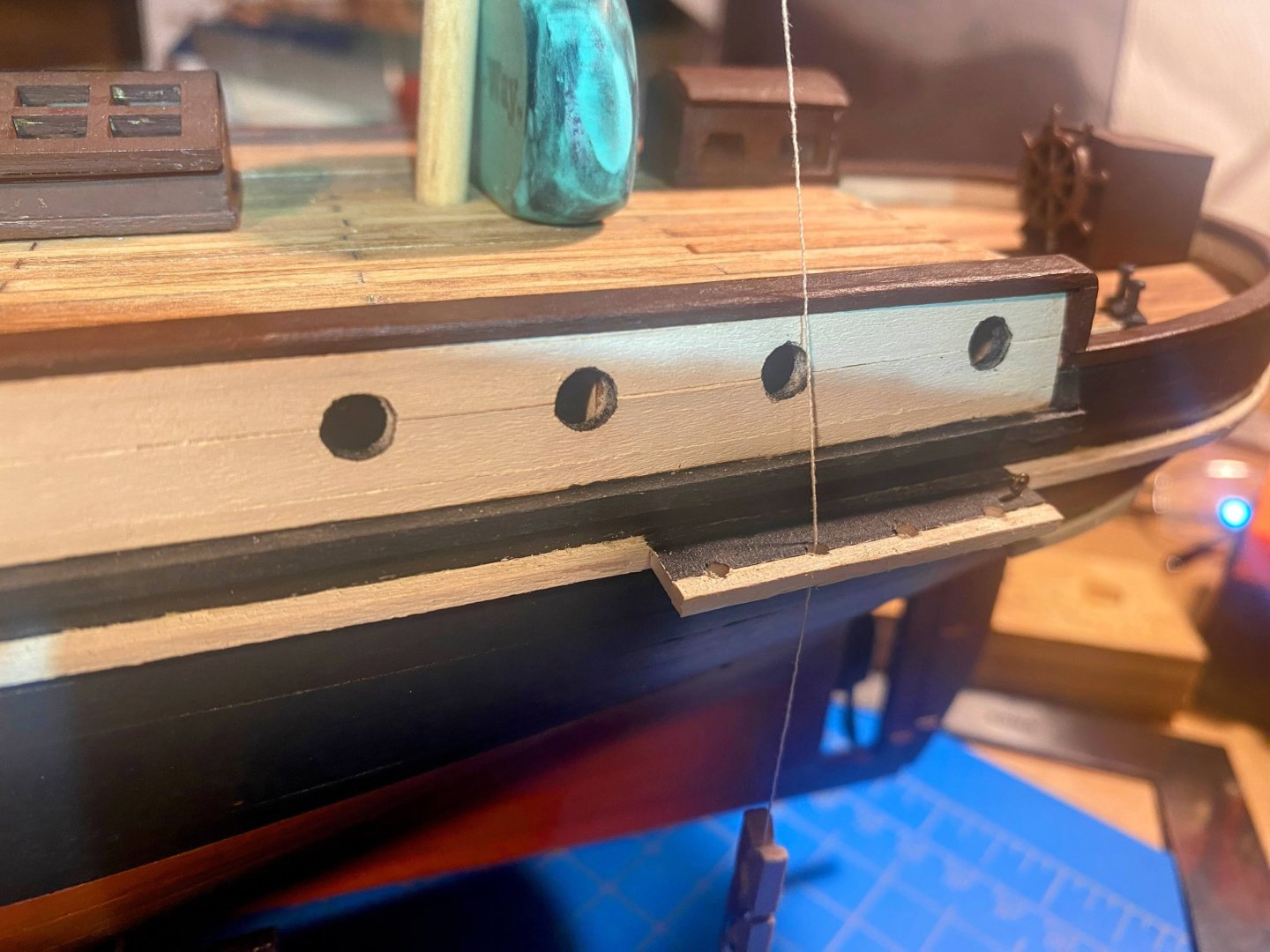
Putting together and gluing in place the next 13 deadeye/chainplate assemblies on the port side took no more time than the first four. Practice didn’t make perfect, but it did contribute a lot to efficiency. Another contribution was using a foot of 2x4 for a roomier jig. Putting together four of these at one sitting is about my limit. 😐 First the mainmast channel. . . For the foremast, OcCre has you simply tie the deadeyes to eyebolts in the caprail, then run the chainstays over the edge of the caprail down to a nail in the hull. That doesn’t look very realistic to me. Also, I remember a discussion in one of the Endurance build logs which raised the subject of a foremast channel, and the consensus was that Endurance did have narrow foremast channels. Without going back to find that discussion and without looking for a photo of the foremast chainplates (not a smart way to proceed), I decided to make my own foremast channels, paint them black and white like the others (but using only a single strip of wood instead of two) and glue them to the white rubrail like the others. One concern I have is that the narrower channels will leave too little room between the deadeyes and the hull to thread the lanyards that connect the lower and upper deadeyes. A challenge for another day.


- 206 replies
-
- 1
-
-
- Endurance
- Shackleton
- (and 2 more)
-
Question Josh, did you do anything special to the brass stanchions before you painted them? And did you use acrylic paint? Your paint job really looks great. And my apologies if you already covered this in your log. My stanchions arrived in the mail today, and getting them ready may provide a nice diversion from working on the channels, chain plates and dead eyes. Thanks
-
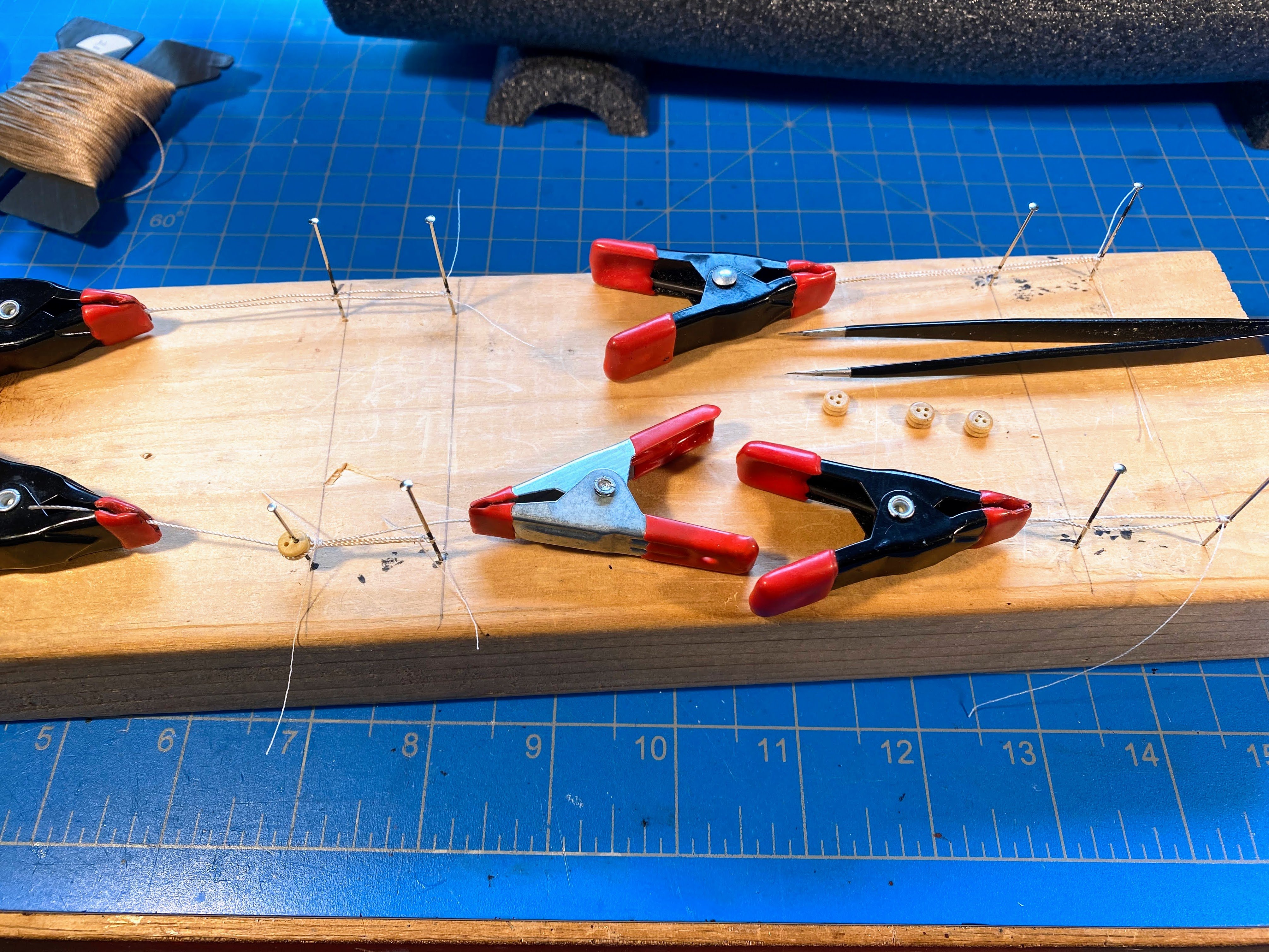
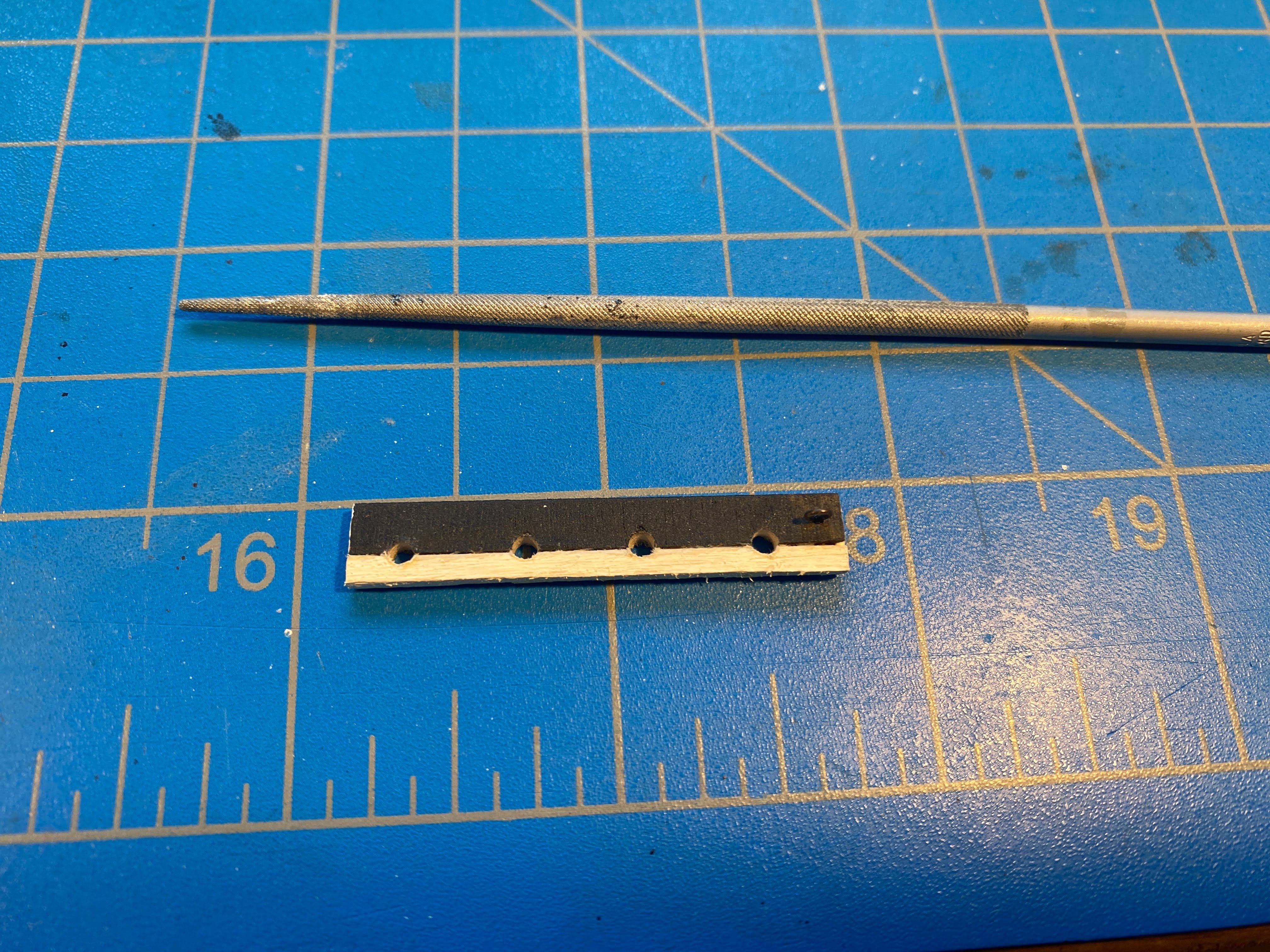
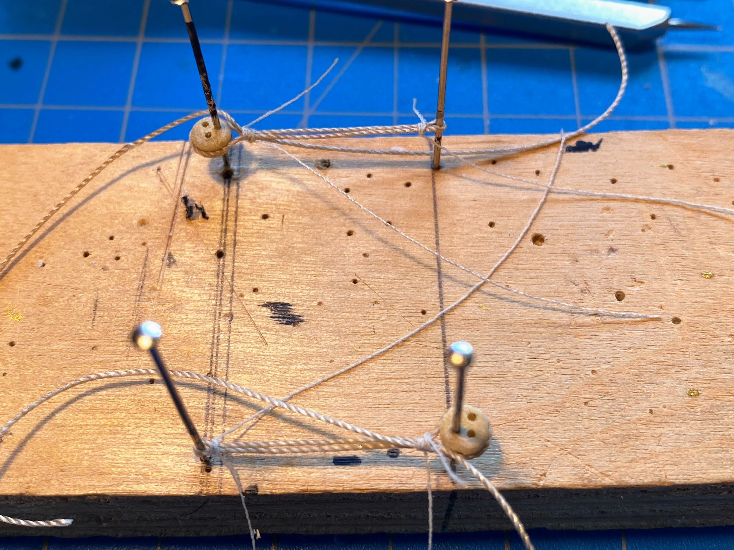
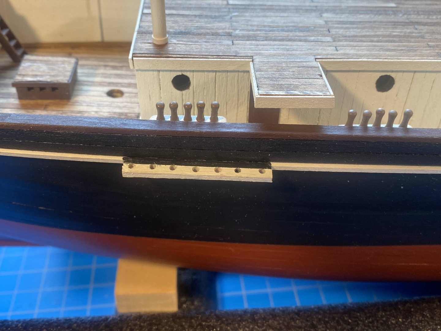
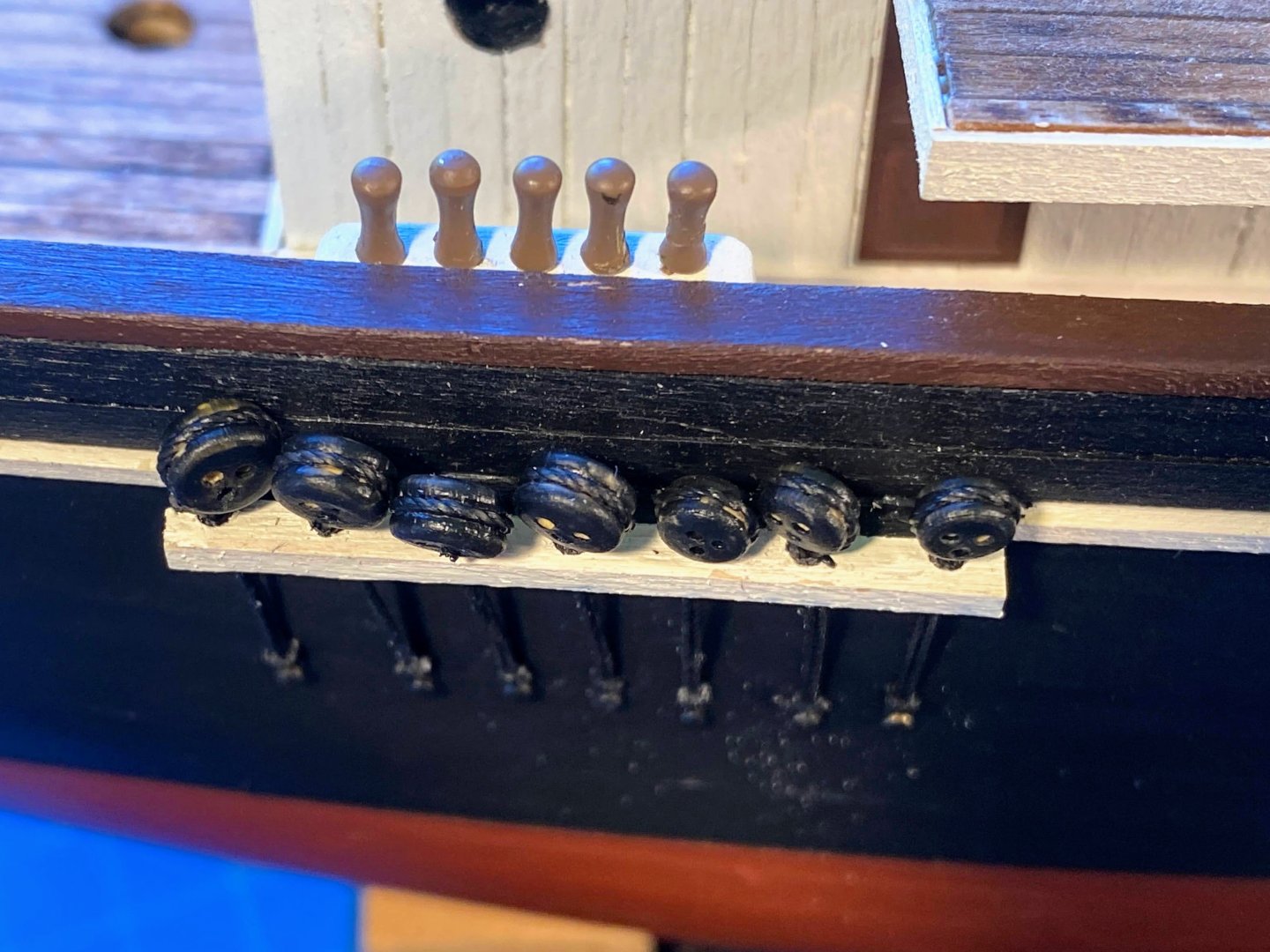
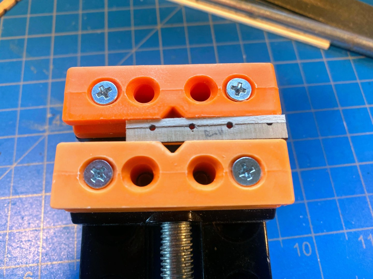
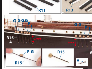
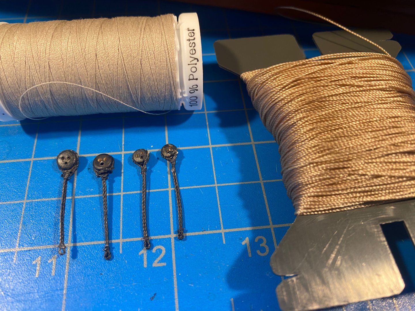
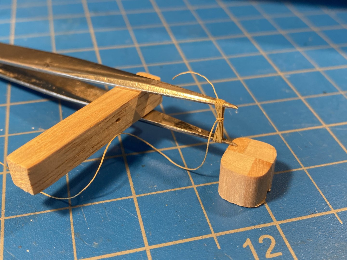
Latest work is on channels, deadeyes and chainplates. OcCre supplies laser cut pieces for part of the mizzen and main channels, including half circle cutouts for the chainplates to pass through. Each channel is to be completed with a 2mm x 2mm strip. Convenient to use two pieces since the laser cut part is to be painted black and the strip white. However the cutouts in the laser cut piece are way too small, as can be seen in the first picture below. I used a 1/16” drill bit and a rat tail file to make the holes larger, but after fabricating a chainplate/deadeye assembly, I found that even 1/16” was too small, and I enlarged the holes a bit more with the file. I spent a lot of time trying to figure out how I was going to make my chainplate/deadeye assemblies. OcCre’s instructions are uncharacteristically unclear at this point, other than they show 0.5mm thread between the deadeye and the nail which secures the lower end to the hull. I interpreted the instructions' photo as wrapping the thread around the deadeye, then twisting the two lengths of thread down to the nail where they would be tied together. The OcCre video (which I looked at only much later) shows simply tying one end of the thread to the deadeye and the other to the nail, and securing the knots with what appears to be CA glue. The best photo I could find of the real chainplates shows straight parallel rods or cables, and Josh (@theoracle09) did a masterful job of soldering wire to duplicate that. I have virtually no experience with soldering and ended up using thread. I started with some leftover thread that was a little thinner than OcCre’s 0.5mm, and took one loop around a sewing pin, then seized the two parts together with thin Gutterman brand thread (also left over). The seizing was simply three hitches. I then pinned the deadeye about 22mm away, looped one thread of the chainplate around the deadeye, brought the other thread up to the deadeye, and created a throat by seizing these now three threads with five hitches of the thinner thread, as can be seen (with some difficulty) in the second photo below. The first two deadeyes I rigged were upside down, and when I first posted this photo, I mistakenly wrote that the deadeyes in the photo were upside down. Not so; I had taken a picture of the do over. Before trimming any of the thread, I doused everything with a generous portion of diluted white glue, my go-to approach to securing knots. I then painted everything black. Only after all of that dried did I trim the ends. The combination of glue and paint makes it all pretty stiff and hopefully assures that none of the seizing will come undone. (I added an extra knot at the throat of the two deadeyes on the left, which I later decided was unnecessary and which I did not do with the other two.) After gluing the channel to the white rub rail, I put a 6mm dowel in the mast hole after marking where the upper ends of the shrouds will be. I then ran some thread from those marks down through the holes in the channels, so I would have some idea how to align the chainplates with the shrouds, which won’t be installed for some time. Despite these efforts, I don’t think I did a very good job of properly aligning the chainplates. Hopefully the fact that the black chainplates don’t show up all that well against the black hull will mean that discrepancies won’t be very evident from a normal viewing distance. But maybe that’s just confirmation of my optometrist’s advice that my eyes are prime candidates for cataract surgery. 😵💫 Only time will tell. At this time I have only 4 of these assemblies completed. That’s out of a total of 34. It’s definitely going to take some time before this part of the build completed.


- 206 replies
-
- 4
-
-
- Endurance
- Shackleton
- (and 2 more)
-
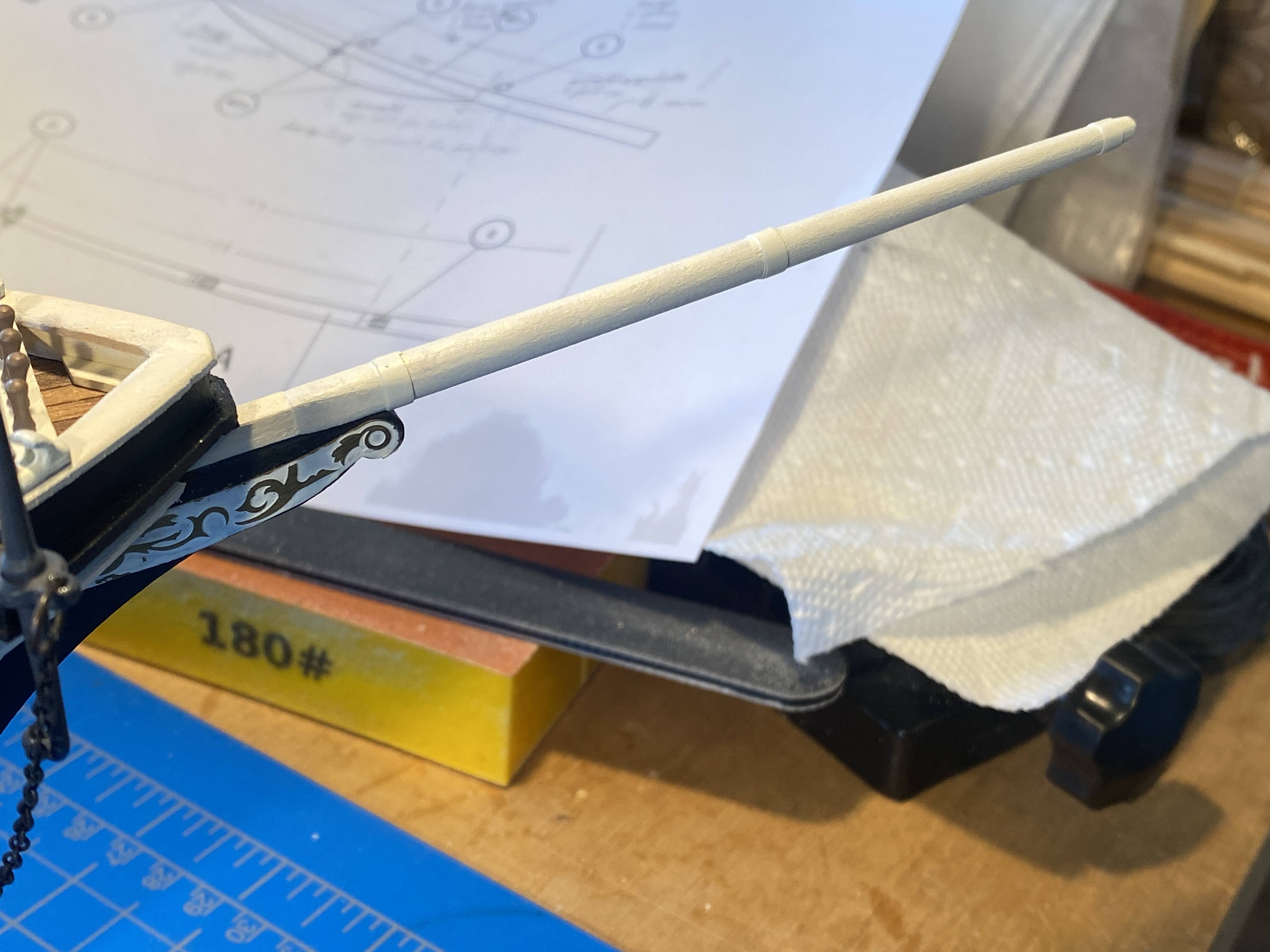
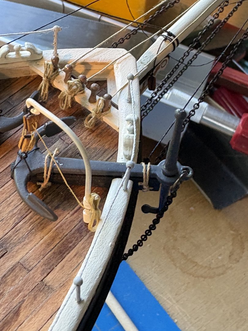
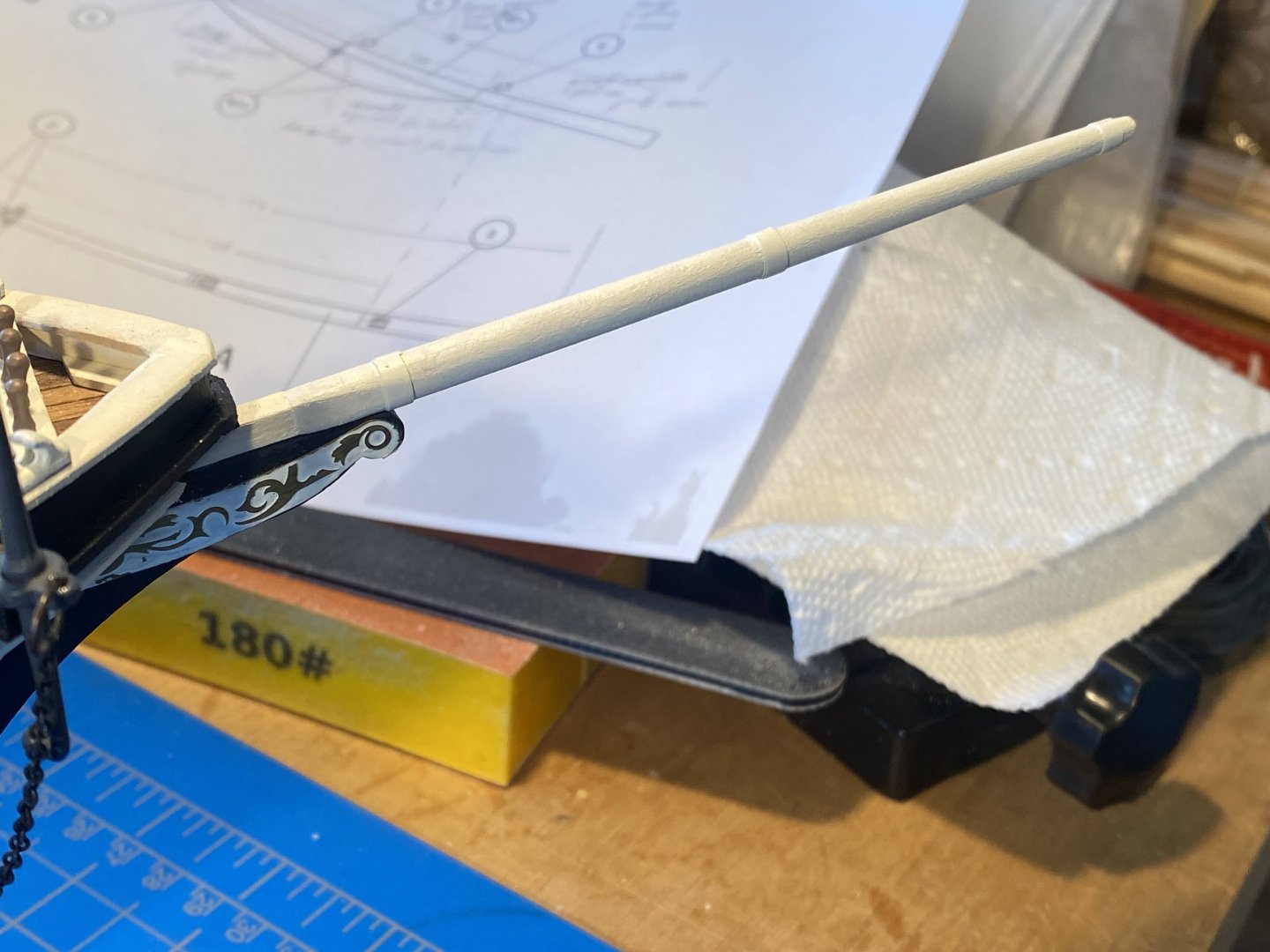
Some time out of town and other activities have slowed things down in the shipyard, and I’m falling behind in my posts to this log . . . A couple of weeks ago I took a break from deck furniture and put a bowsprit together. Two things deserve comment. First, the instructions provide that the bowsprit is to be made from a 6mm dowel, which after some tapering certainly looks like the right size. However, the slot it’s to slide into in the false keel is only 4mm, same as the thickness of the false keel. A long time ago cheeks were glued on either side of that slot, to make a 4mm hole into which the 6mm bowsprit dowel is to fit. Bowsprits and masts frequently have a square base, so I used my Dremel to try to have my 6mm dowel transition to a 4mm square. I made a real mess of things trying and ended up cutting the mess off. I then found some 4mm square stock, and glued it to the inboard end of the now shorter 6mm dowel. Up close it doesn’t look great, but I think from a normal viewing distance it won’t be too noticeable. In any event, I think this is a significant gaffe on OcCre’s part, as it should have provided for a 6mm square slot into which the bowsprit dowel can be snugly fit. Second, without looking at the instructions I installed bands and eyebolts as attachment points for the forestays, and later noticed that the instructions’ photos show the forestays wrapping around the bowsprit. I haven’t found a Hurley photo (but haven’t looked very hard yet) that shows how those forestays were actually attached. Also, the innermost block will have to be attached with a lanyard, so that the line which runs through it has a straight path to the belaying pins, without being dragged across the bow railing.
- 206 replies
-
- 2
-
-
- Endurance
- Shackleton
- (and 2 more)
-
Hi Bill, thanks for dropping by. One of my gripes about OcCre's kit (I assume all of their kits) is that there aren't really any plans. If you download the instructions from OcCre's website, you'll see everything in the kit that's on paper. There is a deck plan, split in two, but that's about it. I do recall seeing though somewhere on these boards hull lines for Endurance, but I don't recall whose log that was in. My recollection is that whoever posted that was showing that the OcCre hull has some inaccuracies. Building the kit exactly as envisioned by OcCre results in a very nice model, but as you can probably tell from my log, I'm enjoying doing some kit bashing. Good luck with your build! Tom
- 206 replies
-
- 1
-
-
- Endurance
- Shackleton
- (and 2 more)
-
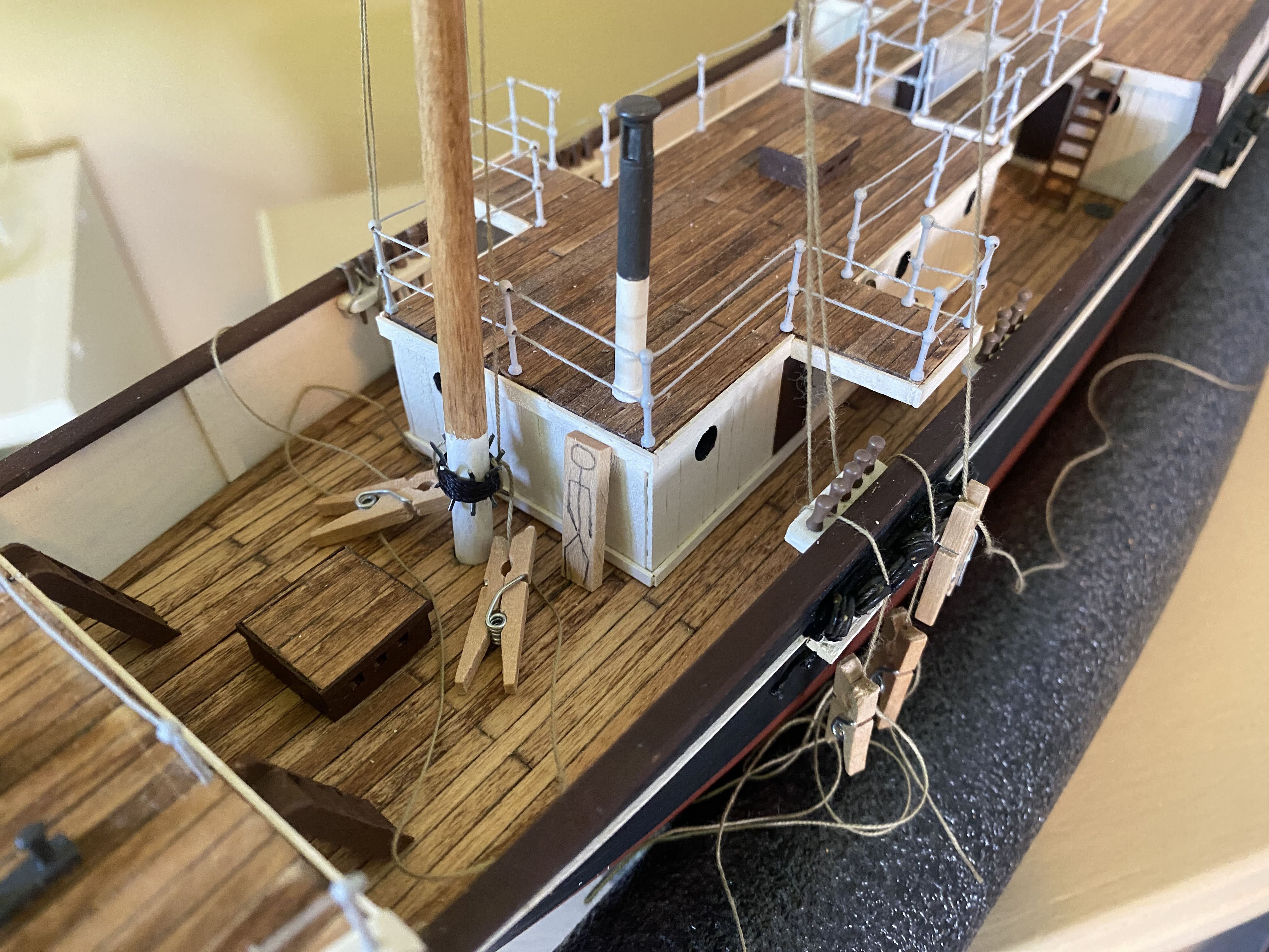
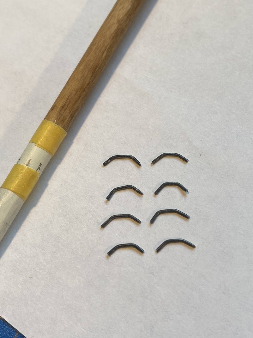
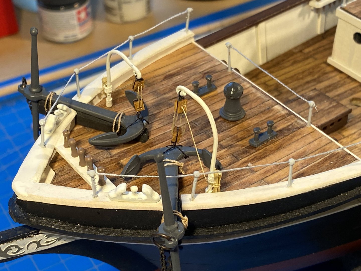
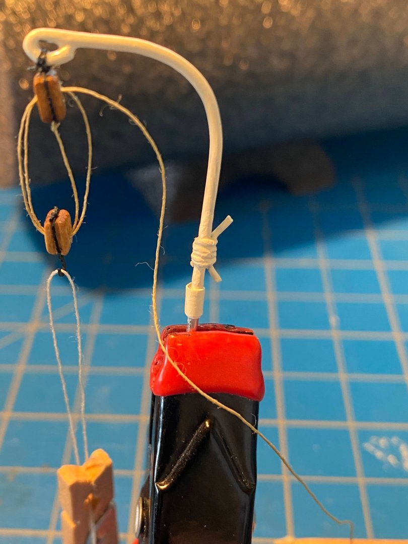
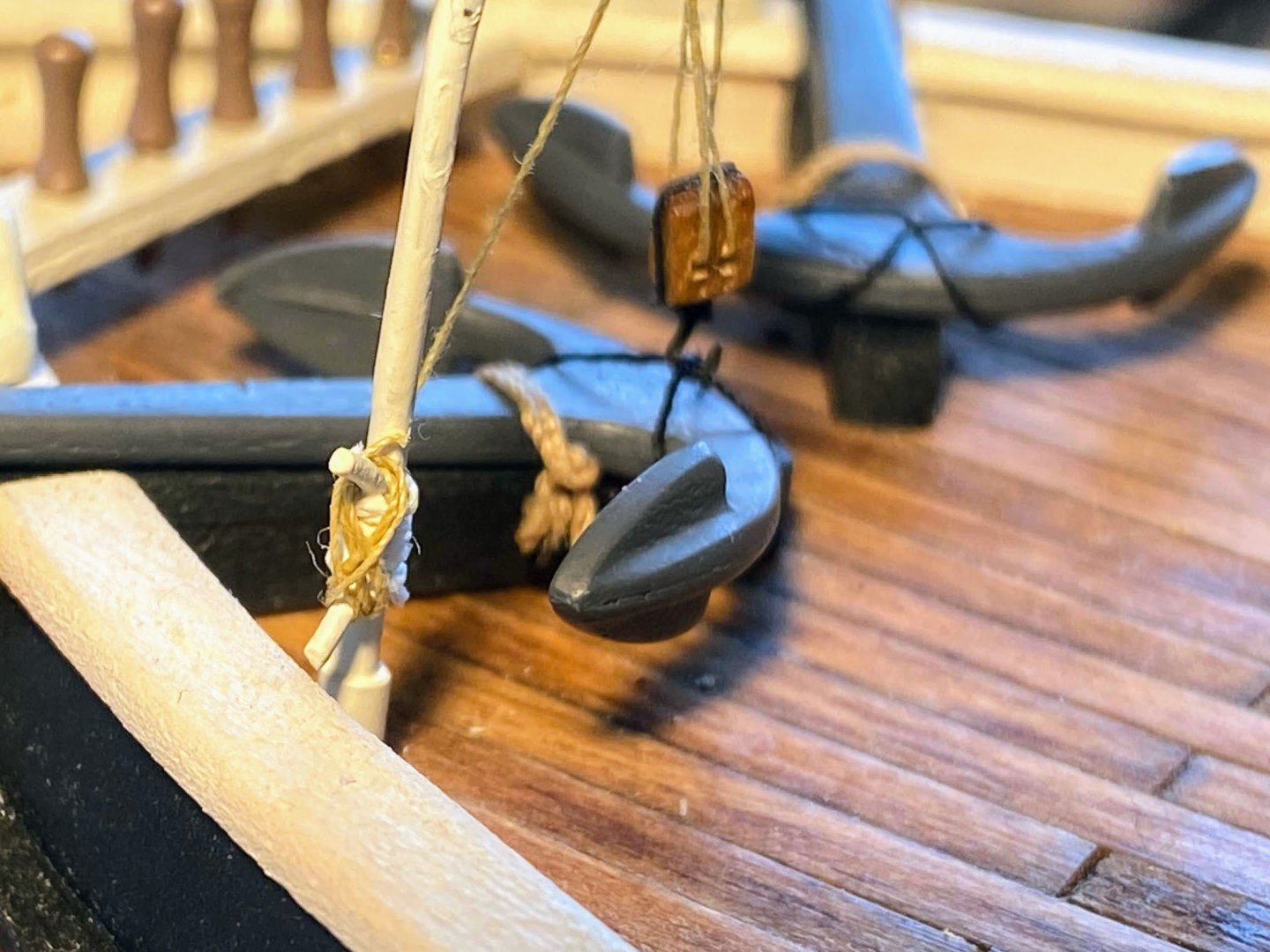
Several weeks ago I built and put in place a couple of anchor davits. But they lacked cleats to secure the working end of the tackle, a project I left for another day. Another day (actually a week or so) arrived recently, as I pondered away many an hour wondering how I would make a couple of cleats. While not simple getting there, the solution I finally came up with was quite simple. I took about ¾” of an inch of small gauge wire and bent the outer third at each end about 30°. I then lashed the cleat to the davit with some relatively thick thread. I “secured” the thread with a hitch at each end; otherwise the two pieces were simply wrapped together. I doused the thread with diluted white glue, and when that had dried, I painted it white. The glue and paint meant all was secure, not merely “secure”. After cleating the tackle in place, I cut it short and added diluted white glue. Finally I created two rope coils using tweezers as a jig. You might recognize the block the tweezers are lying on: that is the piece I cut off from the wooden core of the funnel, described in my recent postings. Incidentally, the small clothespin you see in the first photo below was part of a great Amazon find . . . dozens of cheap, very light weight, 1” clothespins, that I have found to be an invaluable aid in rigging.

- 206 replies
-
- 4
-
-
- Endurance
- Shackleton
- (and 2 more)