HOLIDAY DONATION DRIVE - SUPPORT MSW - DO YOUR PART TO KEEP THIS GREAT FORUM GOING! (89 donations so far out of 49,000 members - C'mon guys!)
×


Tomculb
-
Posts
345 -
Joined
-
Last visited
Content Type
Profiles
Forums
Gallery
Events
Everything posted by Tomculb
-
 Years ago I used Bondo, but it's fumes are terrible and I don't use it (or recommend it) anymore. I think it was Nic at BlueJacket that suggested spackle, which in my experience is used mostly for small holes and cracks in drywall. It's most commonly found in powder form, which needs to be mixed with water, but I found some spackle paste lying around the house, which is pre-mixed. I usually find myself "digging" a shallow hole in what's in the container and mix in a few drops of water to get the consistency I want. I find it works really well and is very easily sanded. Only drawback is that it's white, so it's only appropriate for wood that's going to be painted.
 -
Nice work Chris as an interviewee, although I suspect all of us at MSW would appreciate your holding on to your day job as a model ship kit manufacturer, saving your stage and screen career for the occasional cameo appearance. 😀 Since the subject of future projects has come up on this post, I thought I would throw in my two cents. How about a model of the HMS Beagle? Although initially launched as a brig sloop (perhaps a successor to Harpy?), she was converted to a bark before she went anywhere, and she came along several years after that ship. And although launched as a man-of-war, she was used almost exclusively for surveying. Most obviously, what made her famous was the renowned scientist on her second voyage, Charles Darwin. Given her design, era, and history, I think she would be a unique addition to your collection of kits. And after my recent experience with OcCre’s Endurance, I know you would produce a far better kit. Personally, I am itching to get started on Grecian (which I bought several months ago), but given the holidays, it may be a while. I may do a build log, but only if I feel I can add something to the excellent logs of those who have preceded me. This looks like a magnificent kit. This is the first time I first chose a kit based on the manufacturer, then only with that decision made, chose the ship I would model.
-
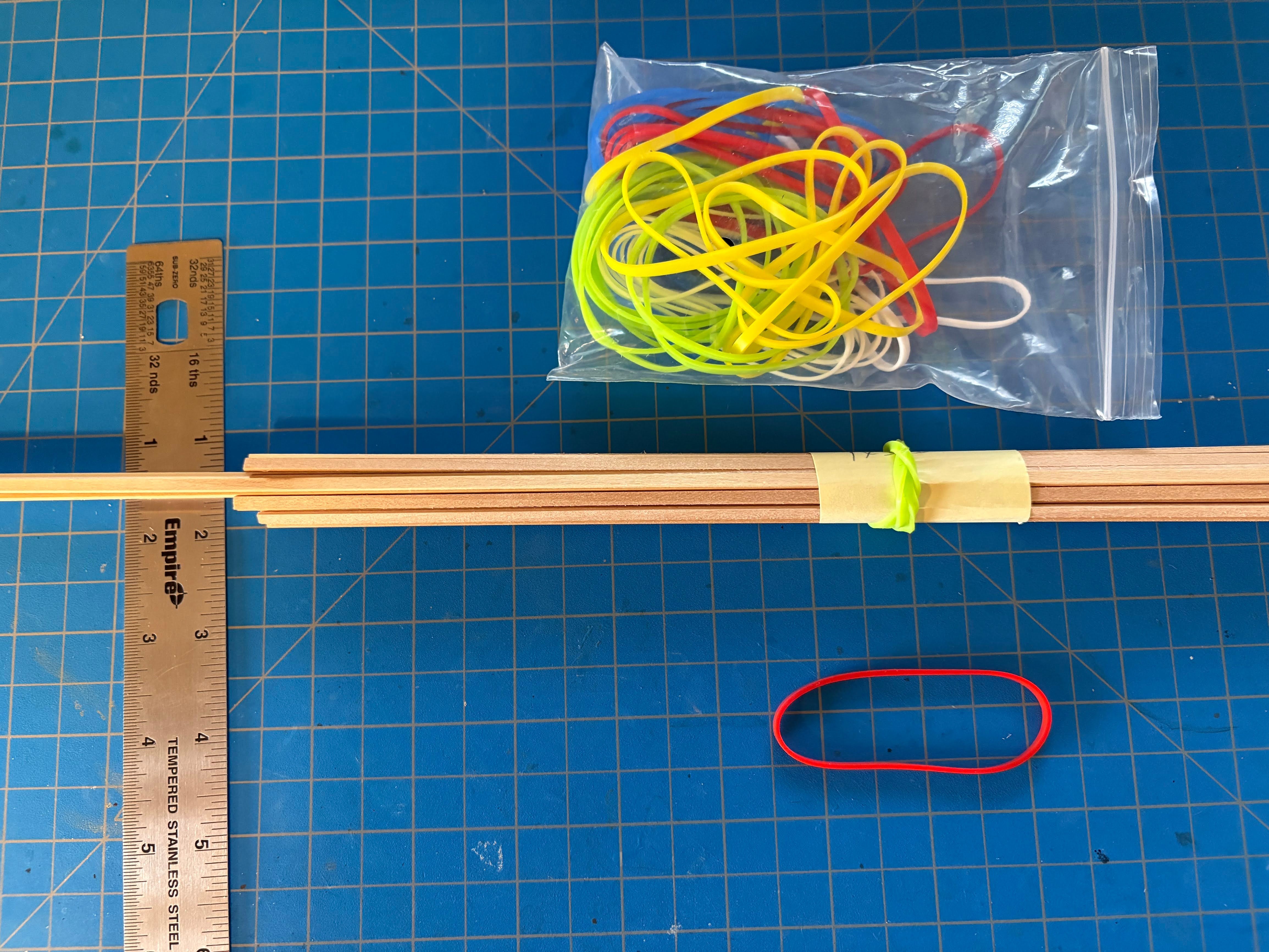
I suspect what you really meant was bicycle tubes, not tires, as you really can't stretch bike tires. Tubes are much more stretchy, so if you cut a few 1/8" bands from a tube, you might have something like a rubber band. I usually have reasons to visit bike shops with some frequency, so I'll give that a try. My only concern is their durability, if they are in fact made of rubber like rubber bands are. A bike tube lives a very long time (assuming you don't get a flat), but it lives in a sealed environment, unlike rubber bands. Let us know if you've used your bike tube bands long enough to know whether they won't deteriorate after a couple of years or so. Doing some Google sleuthing, I learned that the best bands for durability are silicone bands. They are widely available on Amazon. They are used for a variety of purposes, including cooking, since they do not melt at temperatures used in cooking. Their downside is that they don't stretch very well. I bought some 3" long ones, seen in the picture below. Triple banding one so as to hold the roughly 3/4" diameter bundle of strips in the picture below took enough force that I was afraid I might crush some of the wood. Double banding was too loose to hold the wood together. Bottom line is that they don't work very well for my purposes.

-
Your offer of a loan is most generous Tom, and I would think of something to assure you that you'd get it back. Bit of a moot point now as I'm guessing it would be another 2 or 3 years before I want to tackle Beagle, and a lot can change in that amount of time. But many thanks for the thought.
-
A bit belated on my part, but . .. congratulations on a great build, Chimp. Beagle is on my "someday" list, so it's nice to know there's another log for me to follow when I get around to doing my build. In addition to being a pretty ship, I like the idea that Beagle is best known not for its prowess as a ship of war, but for its most famous passenger, Charles Darwin. If you ever get to Ushuaia (assuming you haven't been there already), you'll find that it sits on the Beagle Channel, and its museum has a nice model of the Beagle. Again, congratulations on your beautiful build, and for the great work you're doing on Granado.
-
I haven't been to the post office yet, but the USPS website shows maybe 2 dozen boxes they have available, and none of them are what I want. Thanks for your suggestion Dziadeczek, but the space I have available is horizontal, not vertical. Also, many of my wood strips are considerably shorter than others. My plan would be to cut off the lids, thereby opening up the entire length of the top of each box to facilitate finding what I want.
-
Of the various methods of storing and organizing wood strips described in this forum, the one that would probably work best for me are the 2x2x24 inch mailing boxes. Going online, I see that they are readily available, but only if you want to buy 50 of them for about $50. Far more than I need. Also looked at the UPS Store and similar outlets, without any luck. Has anyone found a source for maybe 10 of them, at a reasonable price?
-
Thanks for the likes and all the kind words. I do hope others will find some usefulness reading my log, since I have been inspired by the logs and comments of many many others on these boards. I hope to see some other Endurance builds; it's definitely a fun project.
-
Several posts on this board reveal some great ideas for storing and especially organizing quantities of wood strips. Often I find it useful to put say all 2mm thick strips in one tube or bag, then separate in that tube or bag the 4mm and 5mm wide strips using rubber bands. But a year later when I need a 2 x 4 strip, the rubber bands have disintegrated into hard brittle pieces. Does anyone know if there is such a thing as a durable rubber band, that will serve its purpose more or less indefinitely? I haven't found one.
-
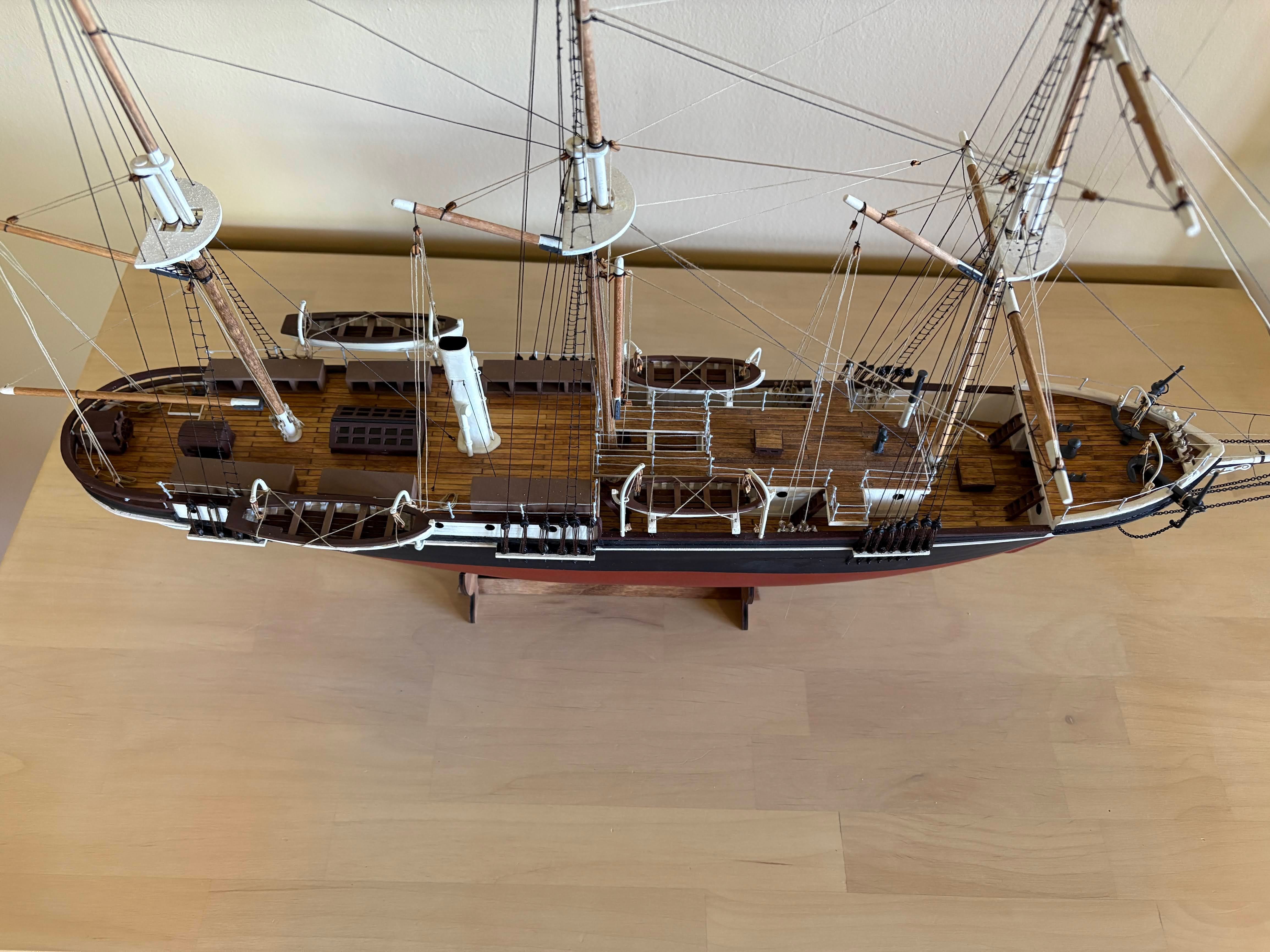
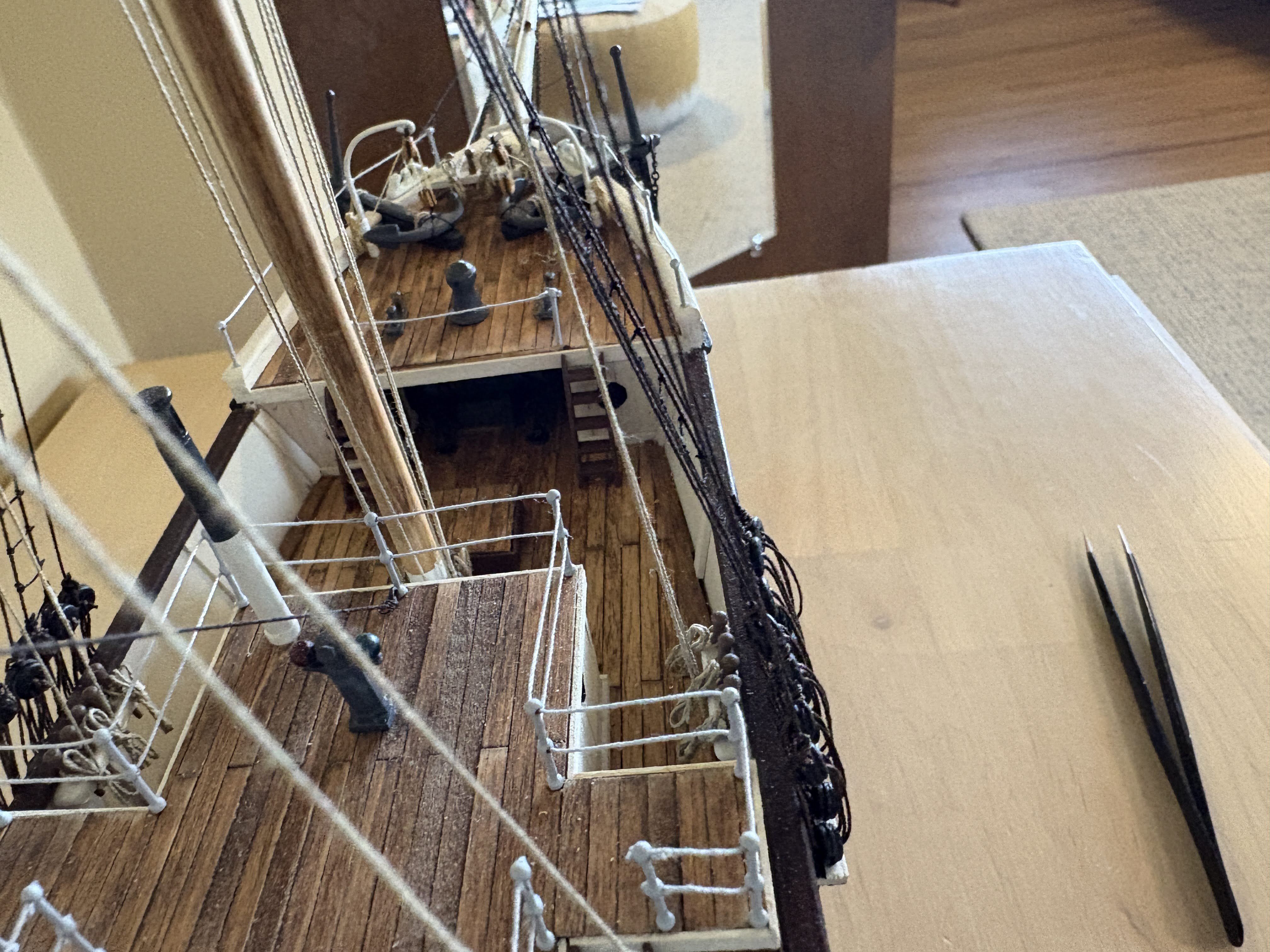
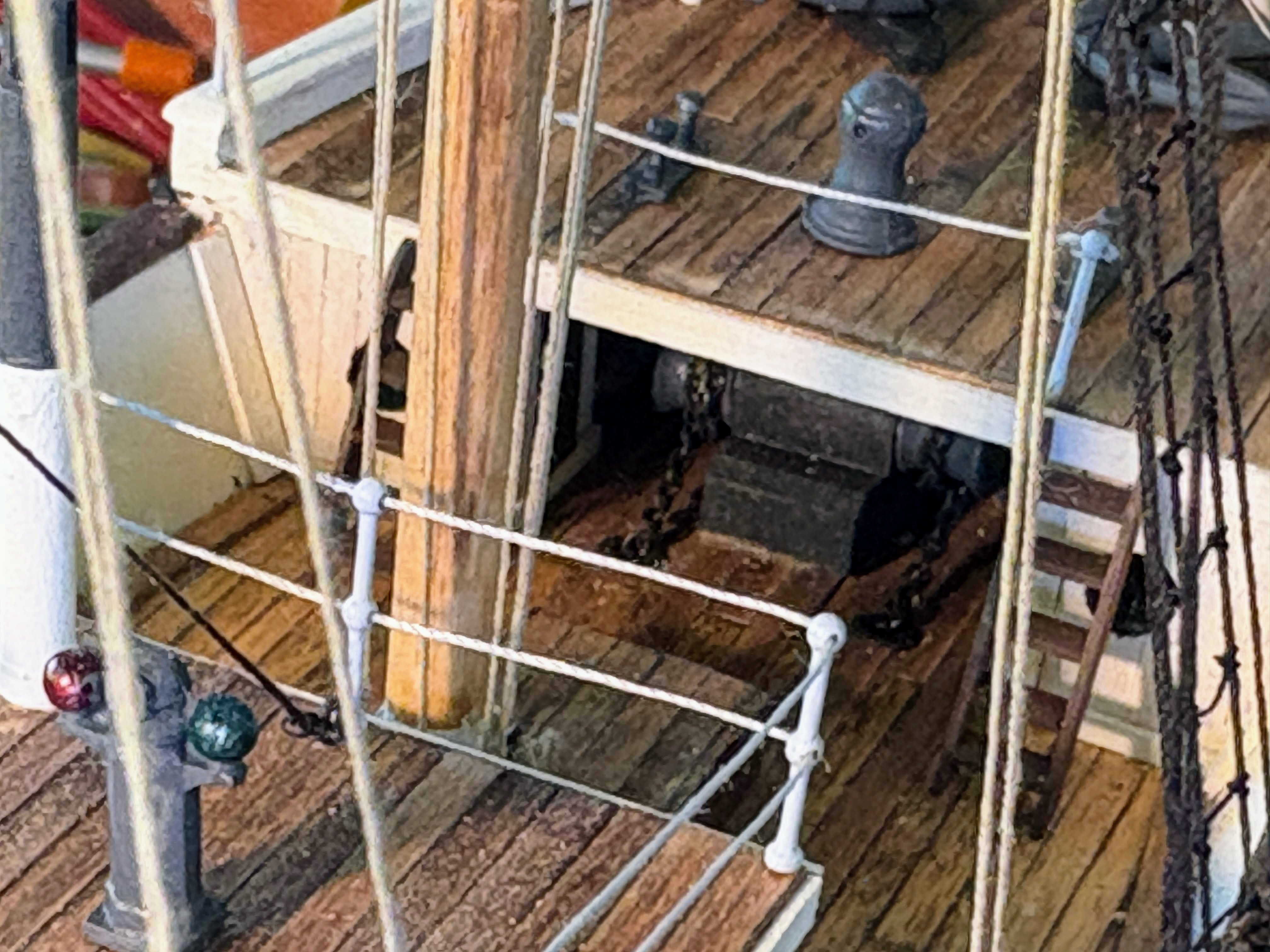
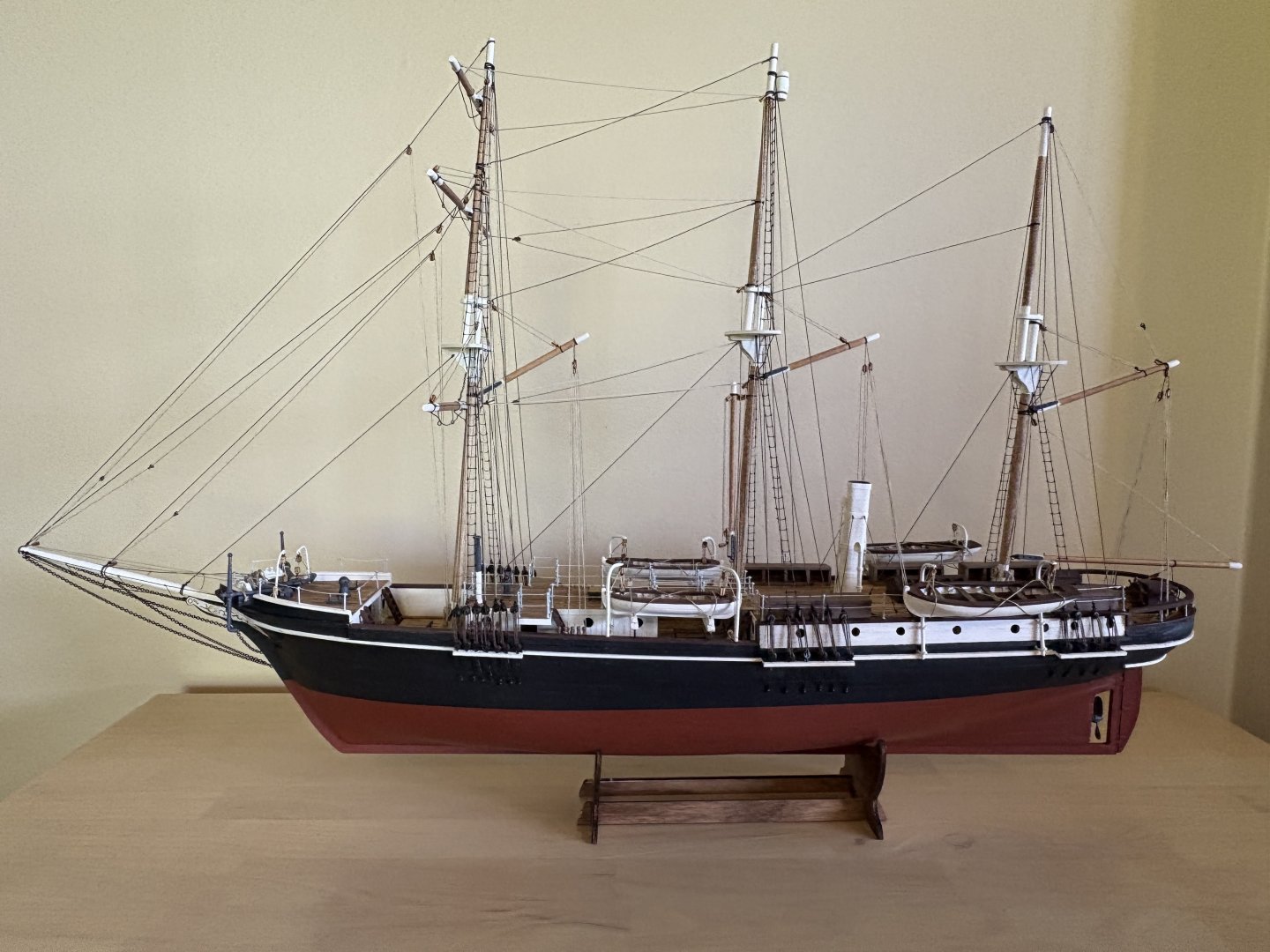
I can now say that after more than 2½ years, my Endurance build is finished. And it has been a wonderful journey. This is my first build with considerable kit-bashing. Doing a lot of research, especially Frank Hurley photos of the ship posted various places online, and then incorporating what I found into the build, was fun and rewarding. I also enjoyed and benefited from others' build logs, but at the same time I was a bit disappointed that so many that were underway when I started (at least a dozen or so) had disappeared unfinished by the time I finished. I think Chris Coyle’s @ccoyle review of the kit matches my sentiments pretty precisely, when he says “The new OcCre Endurance is not what one would call a great kit, but it is by no means a bad kit either. OcCre has economized here and there . . .”. The many modifications I made along the way are described in my log, and there are many more things I could have done but didn’t. Among the latter would be planking the insides of the bulwarks, using better blocks and line from the likes of Vanguard and Syren, and building ships boats that looked more like Endurance’s boats and not so much like OcCre’s. The one thing I did do for which there is no historical justification was to break up the two rows of dog kennels. I’m a little doubtful as to whether that was the right decision, but I’m not losing any sleep over it. I have two kits awaiting my attention: the NRG’s half hull project, and Vanguard’s Grecian. I would like to develop the skills which the NRG kit would hopefully provide me, but Grecian would be a lot more interesting and fun, so I’m almost certain that will be next. It is the first time I have selected a kit manufacturer, then decided on the specific model I wanted to build. I’m thinking it unlikely that I will be doing a build log since there are already quite a few excellent complete ones for both kits. I don’t know that I’d have anything to add to what is already out there. On the other hand, I had that concern about doing a log for Endurance, and now I’m glad I did it. Finally, here are some photos (some better focused than others) . . .


- 206 replies
-
- 12
-

-

-
- Endurance
- Shackleton
- (and 2 more)
-
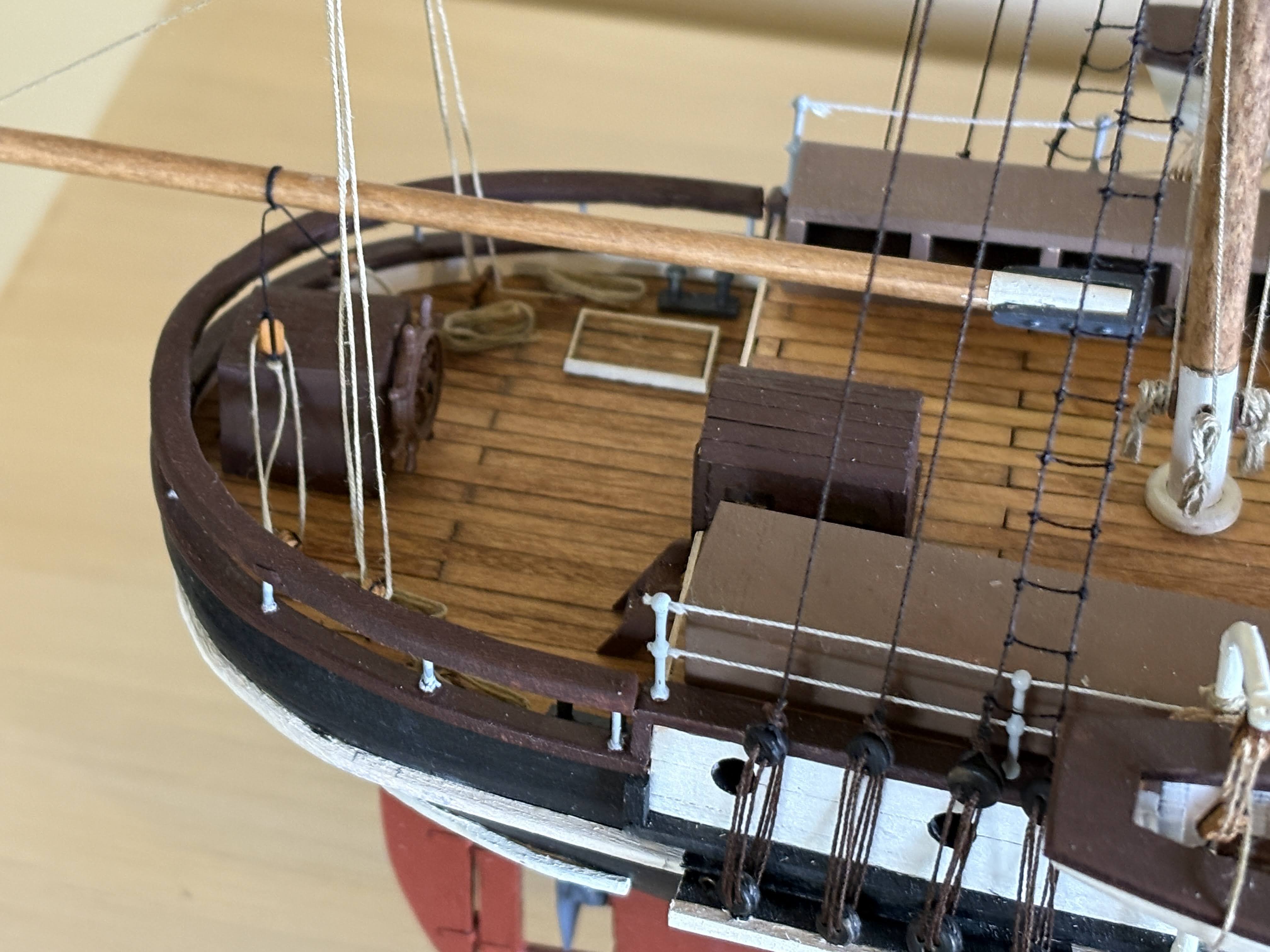
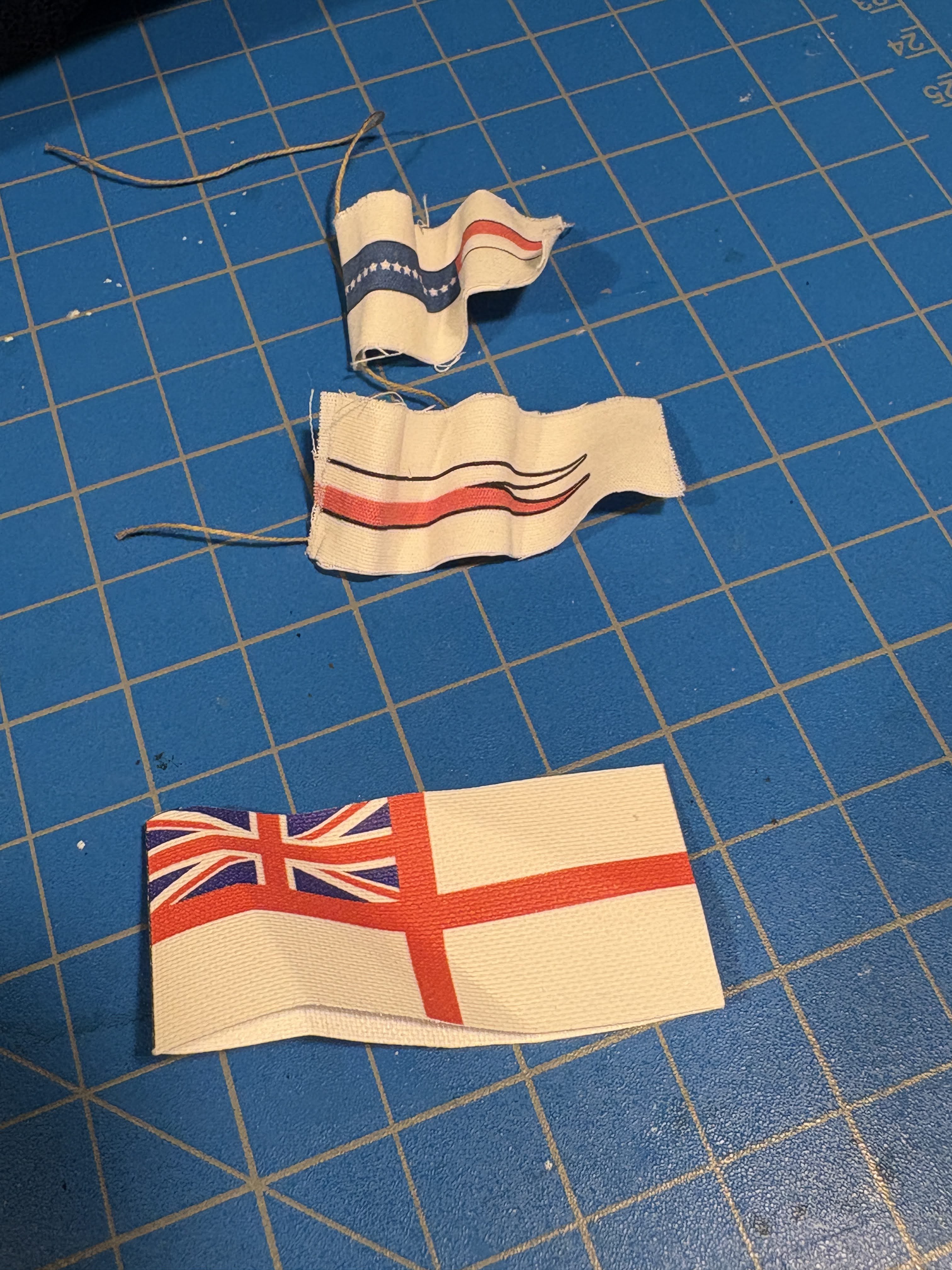
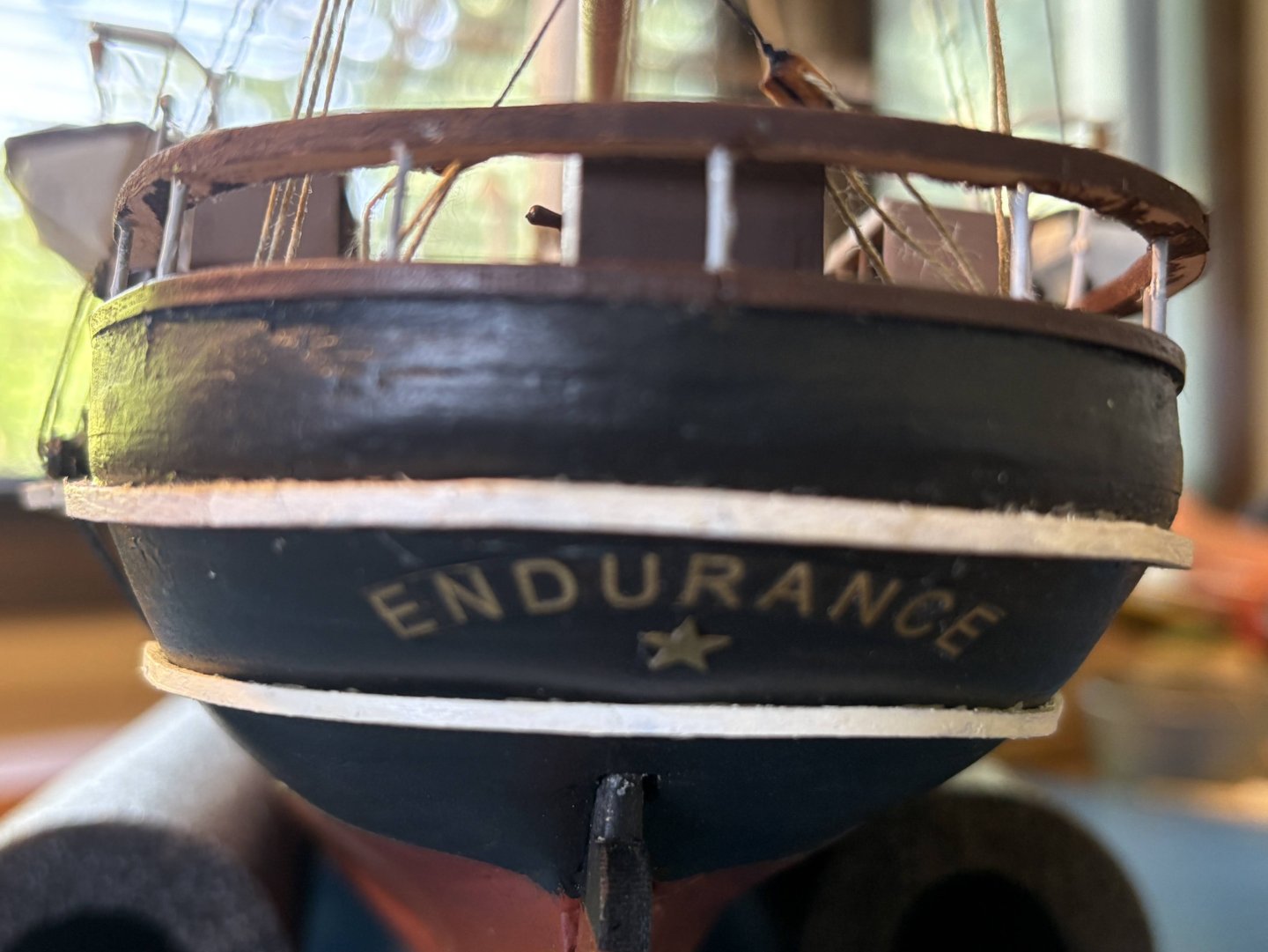
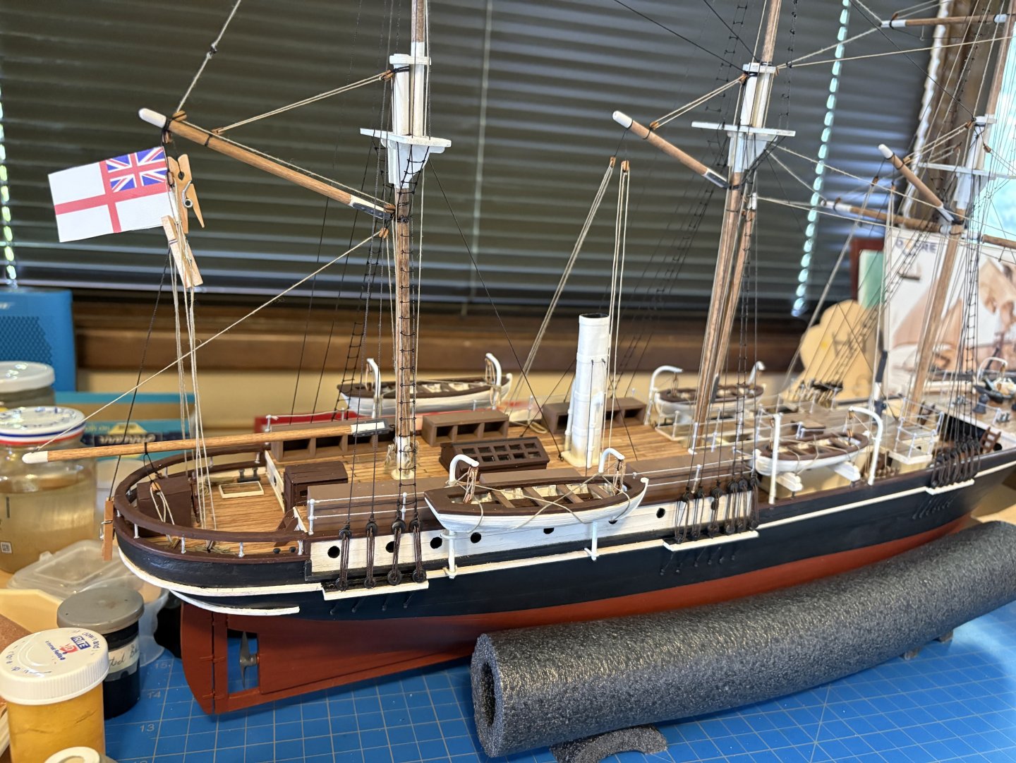
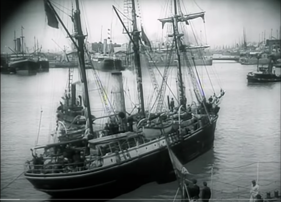
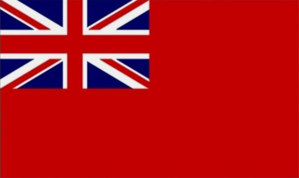
The final task I have been working on is installing the OcCre supplied flag onto my ship. That flag comes as one piece, to be folded in half so that you end up with a flag showing on both sides. After reading a few posts on these forums about making flat flags look much more realistic, I experimented with a flag (cut into two flags) I had left over from a prior build, also intended to be folded in half. I coated the back side of the experimental flags with diluted white school glue (what I use on knotted rigging), lay a piece of thread down the middle as its halyard, and folded the flag in half and let it dry overnight. Once dry, I found I could bend it around a small dowel and I could unbend it and try again if I didn’t quite get the look I was hoping for. So I got up the courage to try this with the Endurance flag. The halyard stayed loose despite the glue, but with the help of some of my tiny clothespins, I hung the flag from the block I had tied to the end of the mizzen gaff months ago. Even before trying to give it some curls and furls, I wasn’t too happy with the result. To my eye, it looked too big and too bright. I calculated that the real thing would be 12' by 5.5’. On the model, it would be the first thing an observer’s eyes would be attracted to. Also, the flags I experimented with were made of somewhat different material from the OcCre/Endurance flag. Unlike the first material I worked with, when I tried to fold and curl the Endurance flag, it didn’t want to stay that way, and the two sides of the flag began to separate. After digging through lots of photos of the real thing, I found one showing Endurance leaving Buenos Aires with a flag which looks noticeably smaller. It was also dark, not mostly white. That led me to inquire of Professor Google, who informed me as follows. The white ensign supplied by OcCre was/is for British naval vessels. British commercial ships display the red ensign, three quarters of which is red, not white. Endurance wasn’t a naval vessel, so its flag should be the red ensign. If any of our knowledgeable British friends (or others) on these boards know otherwise, please let me know. Bottom line, I decided to abandon the flag. My final, finished post will come along shortly.

- 206 replies
-
- 5
-
-
- Endurance
- Shackleton
- (and 2 more)
-
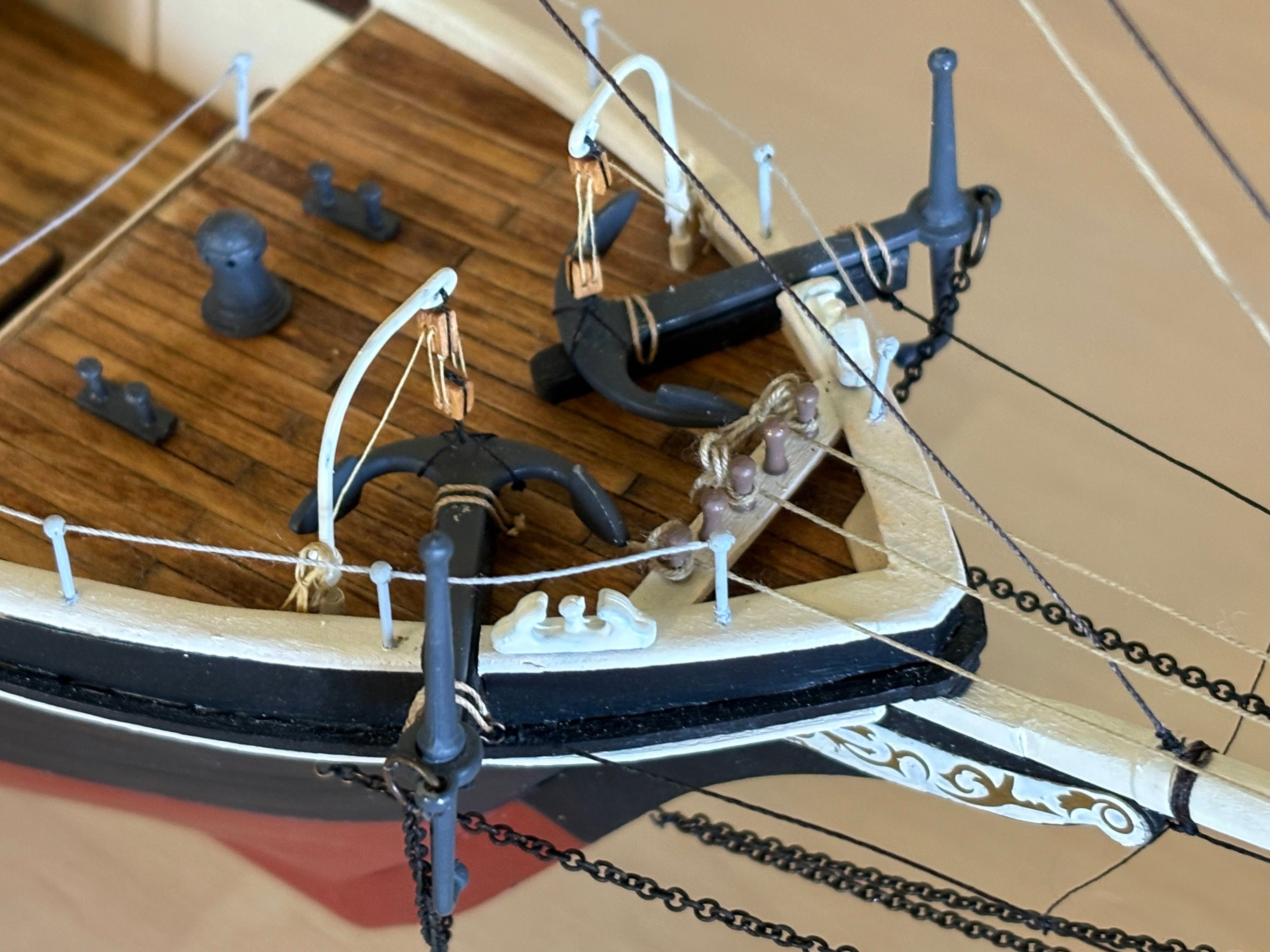
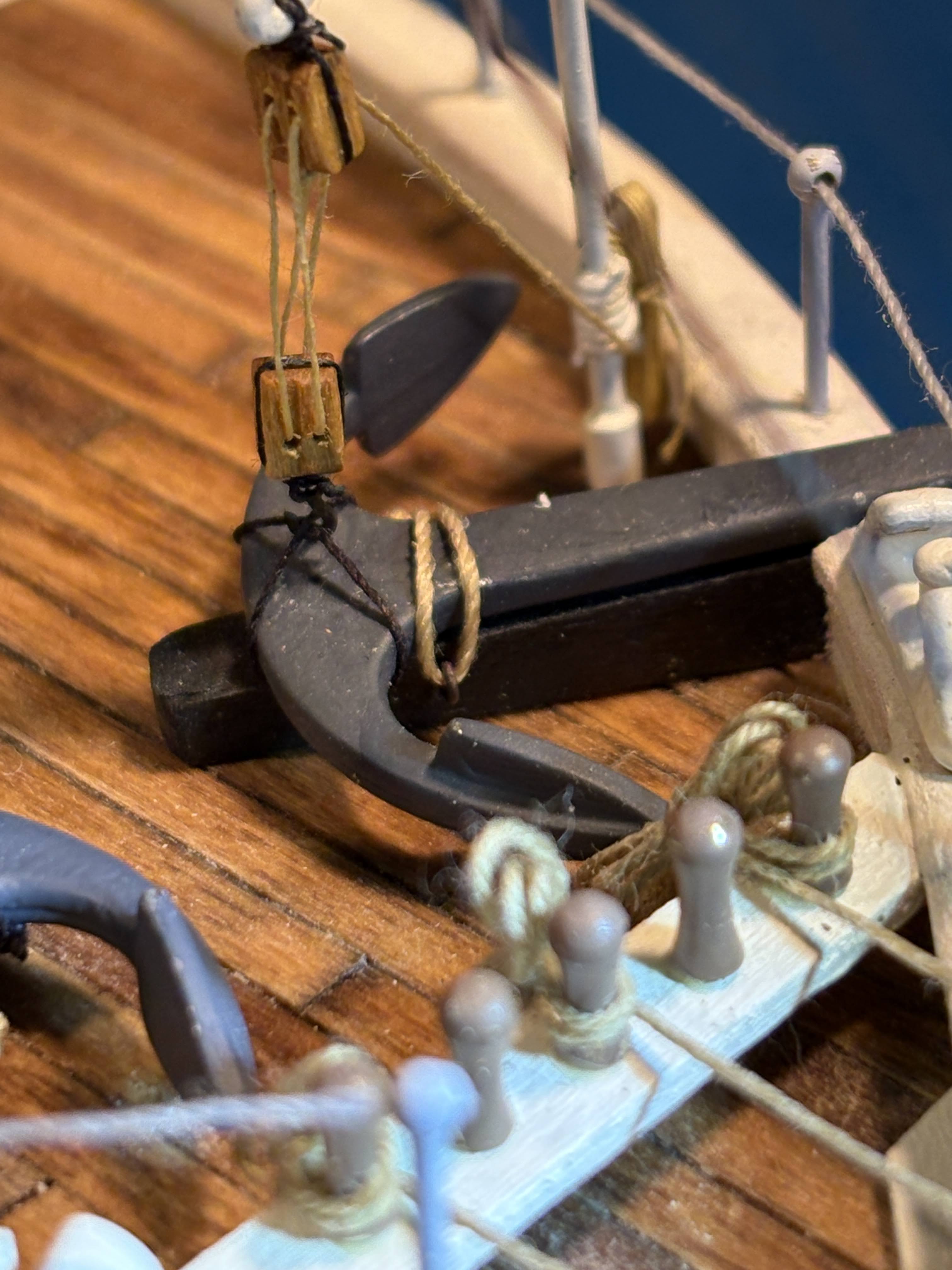
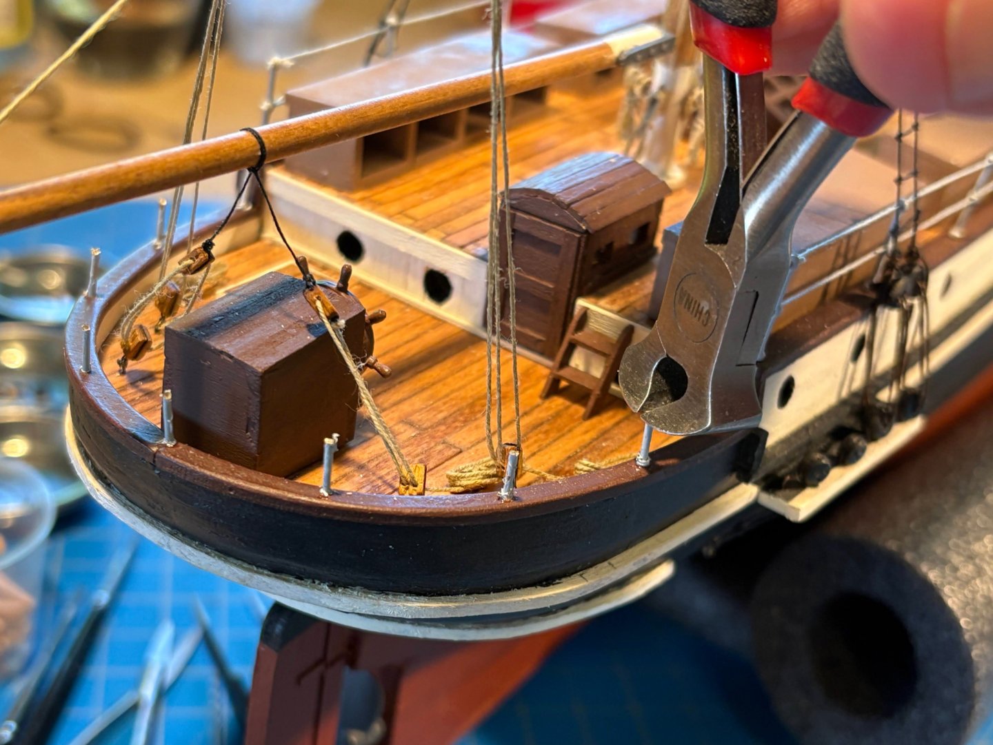
One thing I forgot to mention. The most recent issue (Autumn ‘25) of the Nautical Research Journal has an article by Dick Ritchie entitled “The Twelve Rules of Successful Model Building”. While I think most of the article would be a must-read for beginners (and many of the rest of us), I take issue with his Rule 6, when he says “Identify and fix mistakes before moving forward.” Sometimes subsequent building will render a later fix too difficult or impossible, but if that is not the case, I usually wait for another day to fix mistakes. The reason is that if I do the fix right away, my mind is at least half occupied wondering why I was so stupid as to make the mistake. If I wait a while (sometimes a long while), my mind is completely dedicated to the fix. I mention this because at least a year ago I snagged one of my anchors on something, dislodging the cathead from the deck and pulling out one of the eye rings used to lash the anchor to it. A few days ago I finally got around to doing the fix. It was difficult given all the rigging and fixtures which surround it, but it was doable since my mind was in the right place. I didn’t take a before picture . . . only after. One more task and I'll be finished! 😄

- 206 replies
-
- 4
-
-
- Endurance
- Shackleton
- (and 2 more)
-
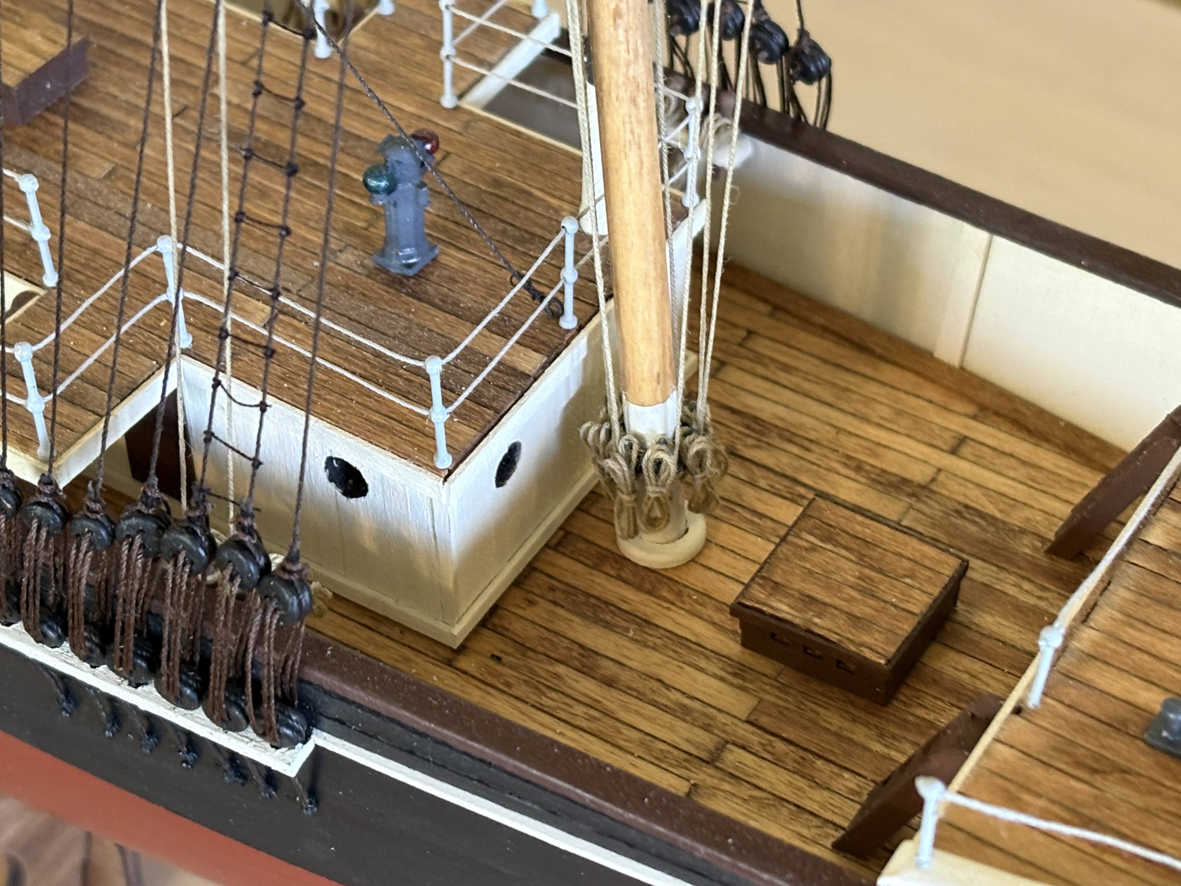
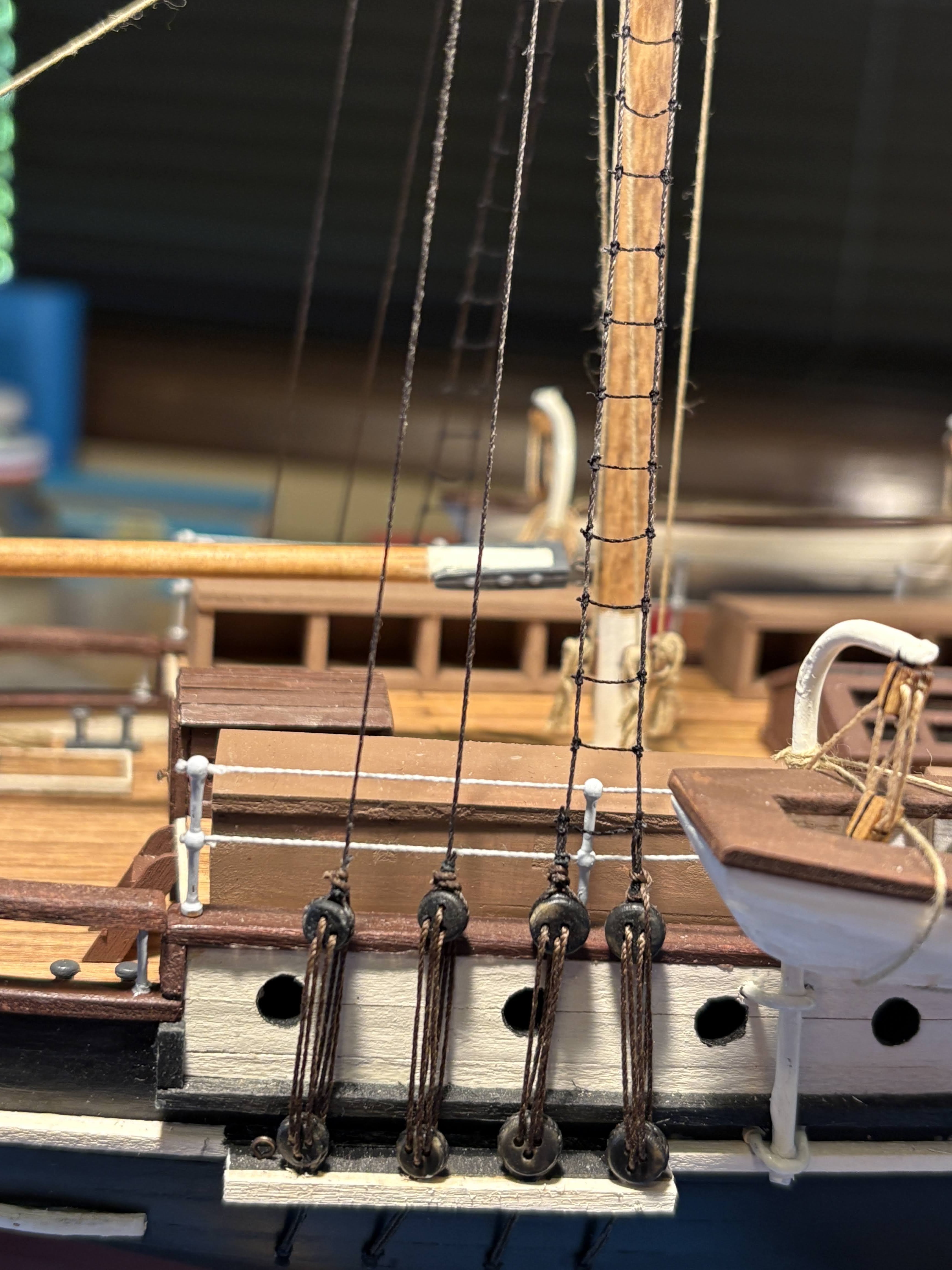
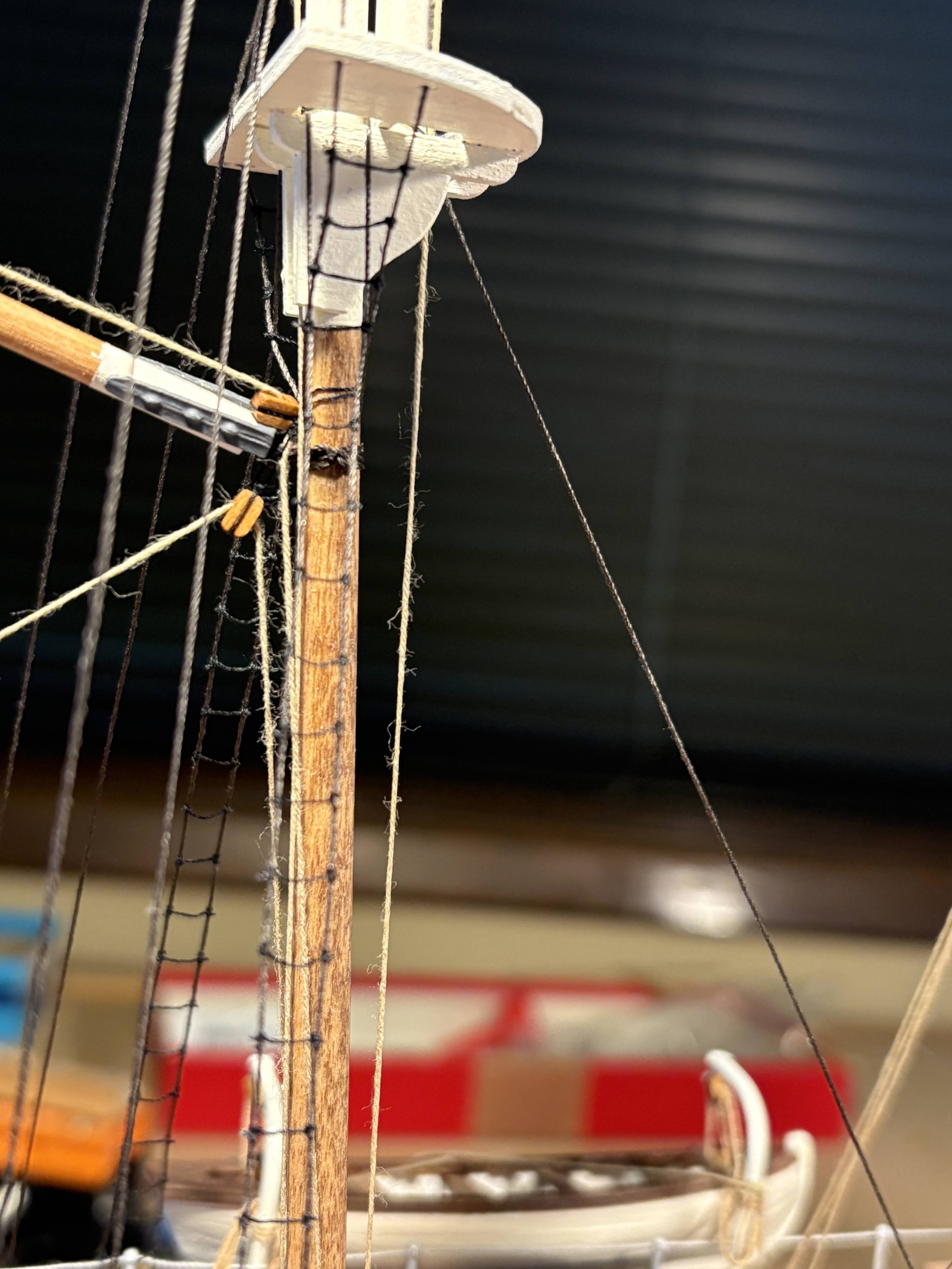
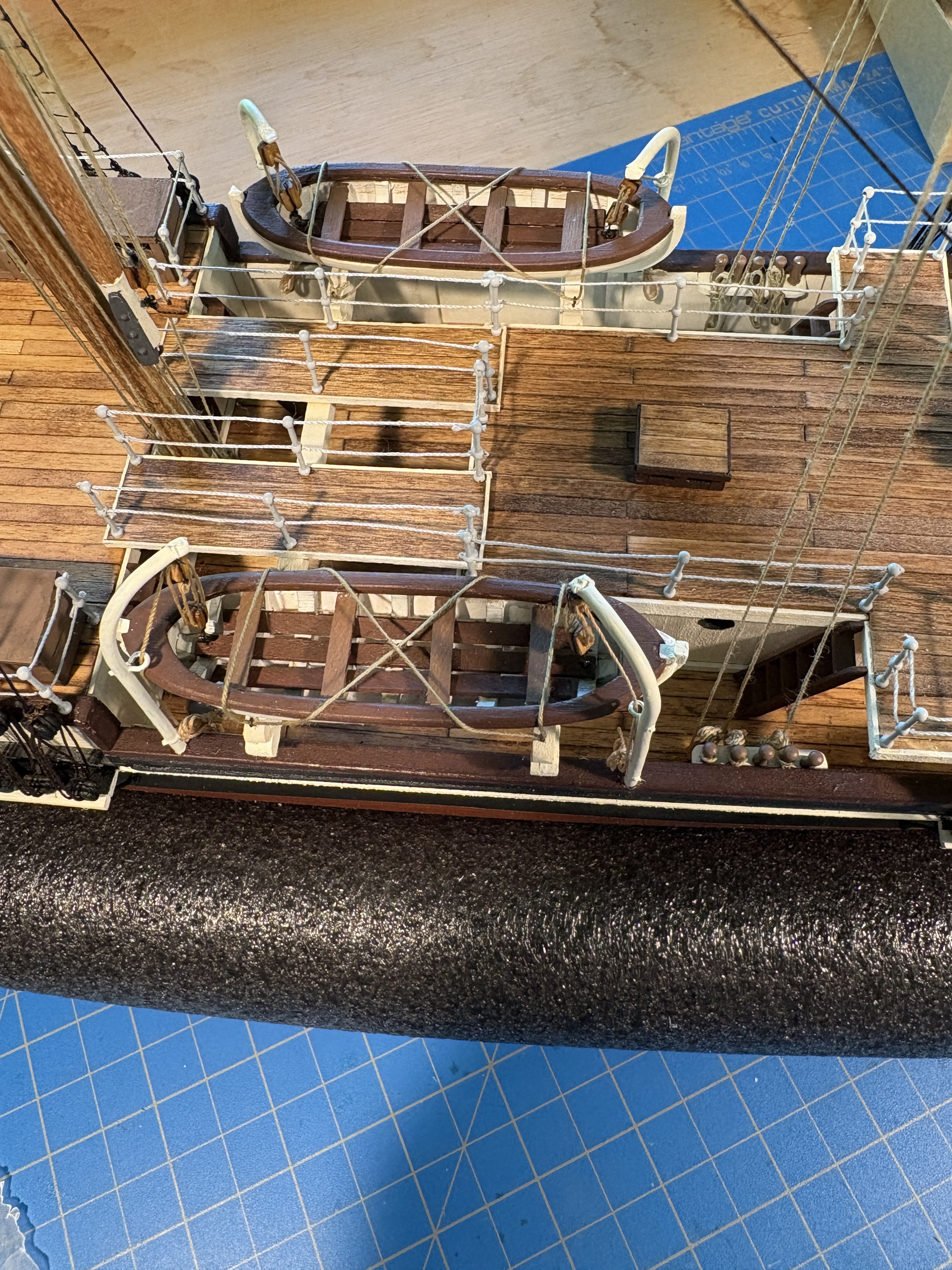
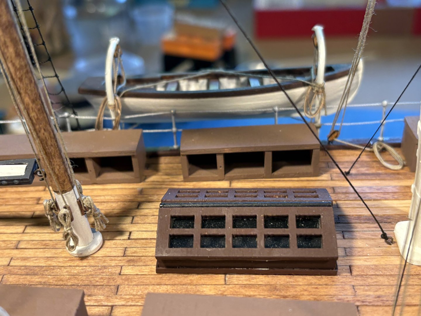
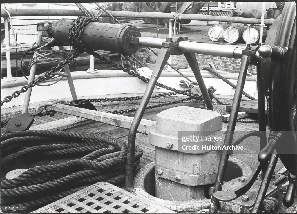
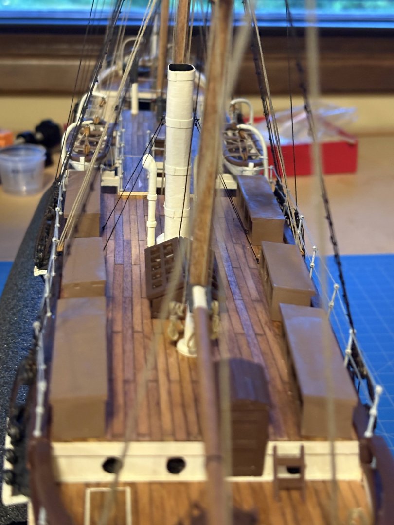
A few small things since my last post . . . Finished the mizzen ratlines, including those on the futtock shrouds . . . Added aft two pair of mizzen shrouds . . . Did a do-over of the port aft ship’s boat aft lanyard coil. Decided to leave well enough with the forward one of those coils. Some time ago I glued a couple of OcCre supplied bollards to the aft deck (in addition to the two already on the anchor deck). OcCre would also have you place bollards at the fore and aft corners on either side of the lower deck, which raised an issue in my mind. Bollards like that are usually used for docking and perhaps towing lines only, not standing or running rigging. But such docking lines would be led directly from the bollard to the dock, not up and over the bulwarks as would be necessary as placed by OcCre. Which made me realize that dock lines would best run through scuppers, whose main purpose was to drain water off that lower deck. But neither OcCre, nor any of the plans I have seen for Endurance, show such scuppers. Were there some sort of internal drain pipes to drain water? Scuppers would be more efficient and more common, in my view, but what do I know? Had I thought about it at the time I probably would have drilled or carved some scuppers along the bottom of the bulwarks, but it’s too late now. In any event, I chose not to install bollards on that lower deck.


- 206 replies
-
- 4
-
-
-
- Endurance
- Shackleton
- (and 2 more)
-
I have heard people say that water based acrylics raise the grain, but that hasn't been much of a problem in my experience. I apply at least 3 or 4 coats of paint, with some sanding in between each of them, and what little grain that has been raised disappears.
-
Sad news indeed. Back in the 70s and 80s I spent my first 18 years of young adulthood living in Hawaii. Most of those years I raced Hobie catamarans, first 16s, then 18s. One of those years I served as fleet captain and arranged to have our end-of-the-season awards dinner catered aboard the Falls of Clyde. It was a glorious evening I'll never forget. While I have been back to Oahu and other islands a number of times since then, I was unaware that she had fallen into such serious disrepair. She was a beautiful ship and certainly appeared to be well cared for and was well loved. It's a tragedy something couldn't be done to save her.
-
Tom, you're doing great work on your Beagle. I have bookmarked your build log. Beagle has been in my "I wanna build it someday" category for some time now, but probably a year or two away at best. I'm just finishing OcCre's Endurance, and as I did with that build, I would want to kit bash a Beagle build enough that it doesn't look like, and is more accurate than, a typical OcCre kit. My next build is Vanguard's Grecian Baltimore clipper, and I may try to talk Chris into putting out a Vanguard kit for Beagle. I might even offer to buy your AOS book when you're finished, but to be honest, if I got a similar request I'd probably be inclined to say "I'm not interested in selling." In any event, I hope you enjoy your Beagle as much as I have enjoyed my Endurance.
-
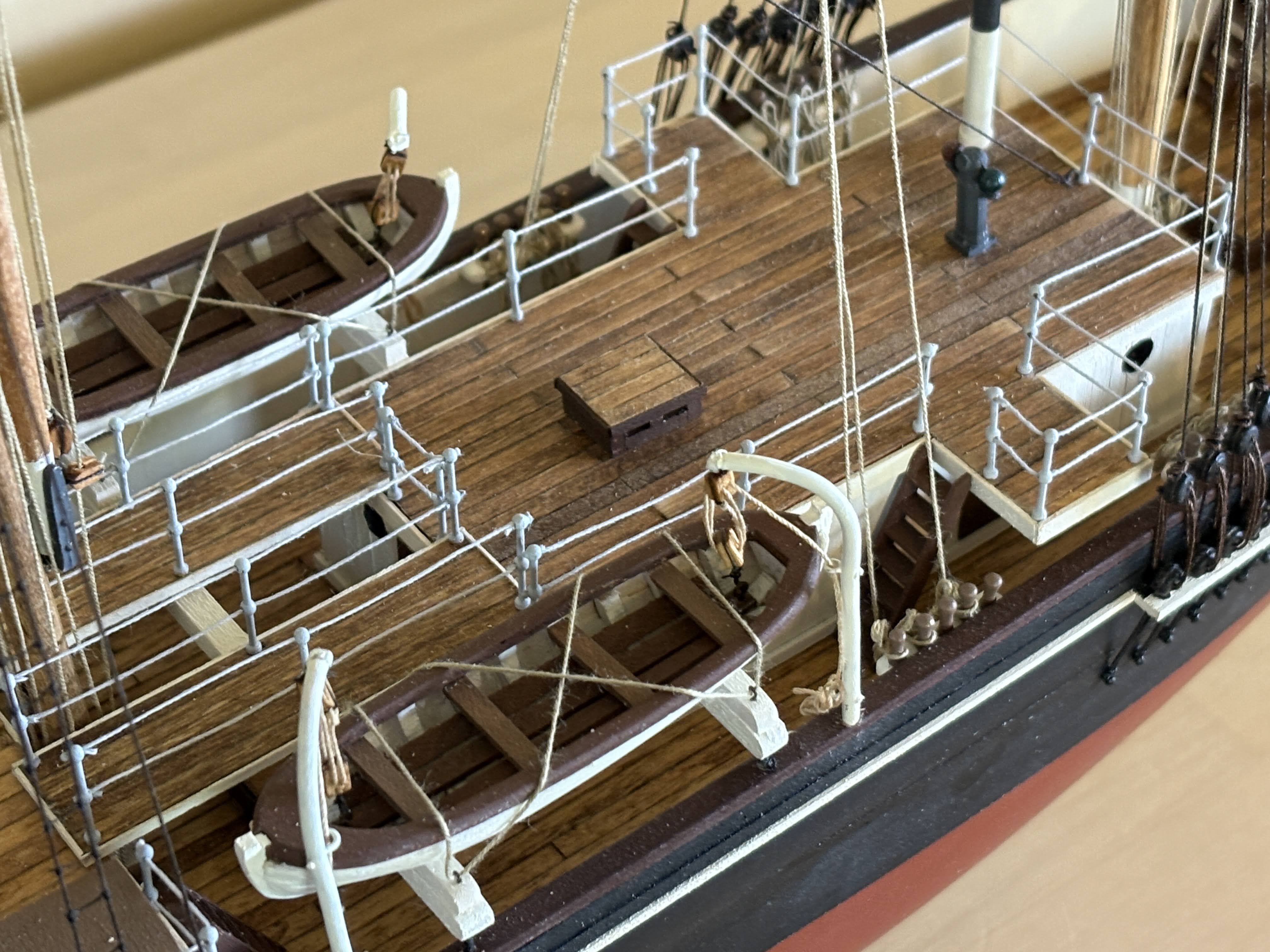
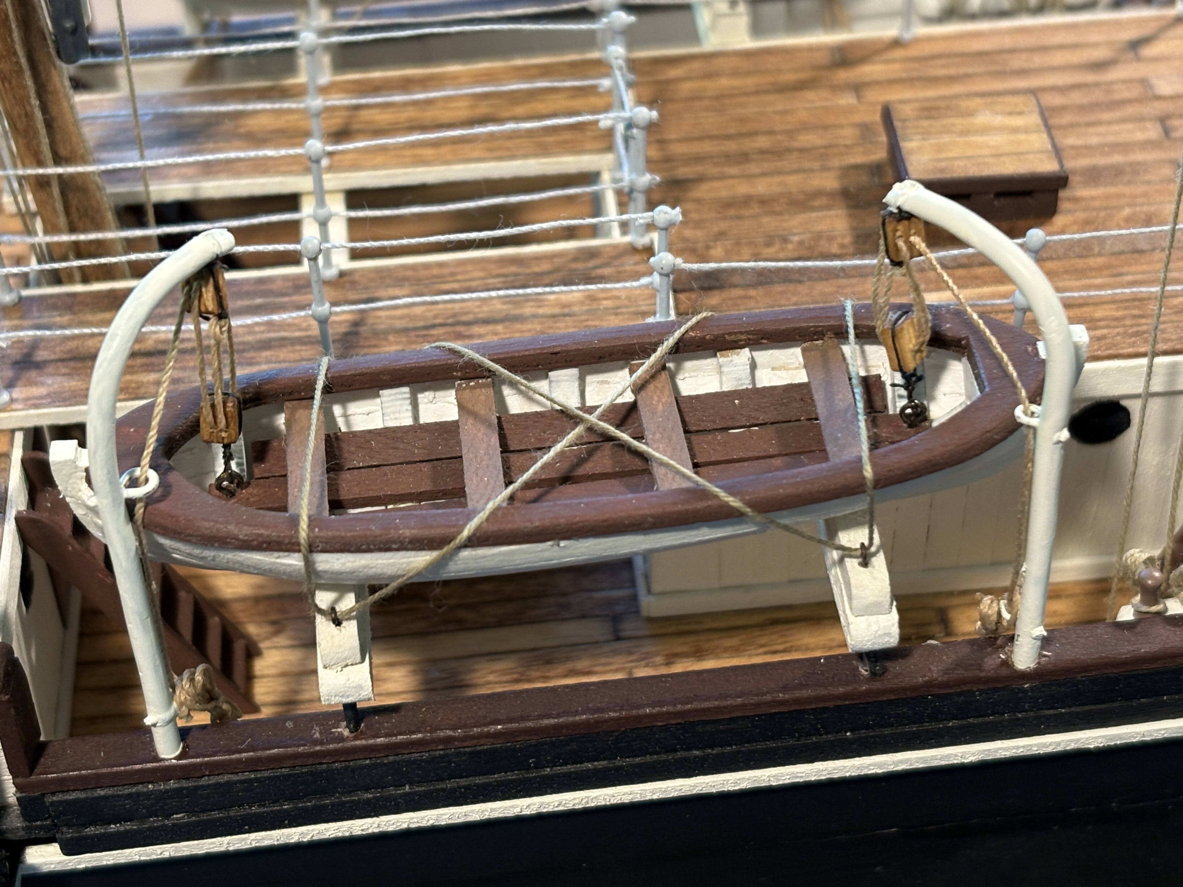
Six or seven weeks have gone by since my last post, and all I have accomplished in the meantime is building the one remaining ship’s boat and building and installing davits for it to hang from. Some great travel and nice autumn weather have kept me outdoors and away from the shipyard. As I did with the forward pair of boats, the lower block of the tackle is attached to the eyebolt in the boat’s hull with a hook; obviously that block would not likely be tied to the eyebolt as OcCre would have you do it. This time I cut the line in that tackle long enough so that I could make a rope coil to hang from the davit. The coils look a lot better than what I did on the opposite side, where I will do a do over. The light at the end of the tunnel is getting brighter, but still a number of things left to do. 🙂


- 206 replies
-
- 7
-
-
- Endurance
- Shackleton
- (and 2 more)
-
I'm slowly getting to the finish line with OcCre's Endurance, and among the many areas in which I felt the kit fell short, it didn't include any plans, other than one of the deck. I love just looking at plans, in addition to they're being invaluable in building the model. Grecian is on deck in my shipyard. I bought the kit several months ago fearing supplies may run low with our administration's destructive tariffs. It is the first time I have chosen the manufacturer first, then chose which kit. I'm very excited about experiencing a Vanguard build.
-
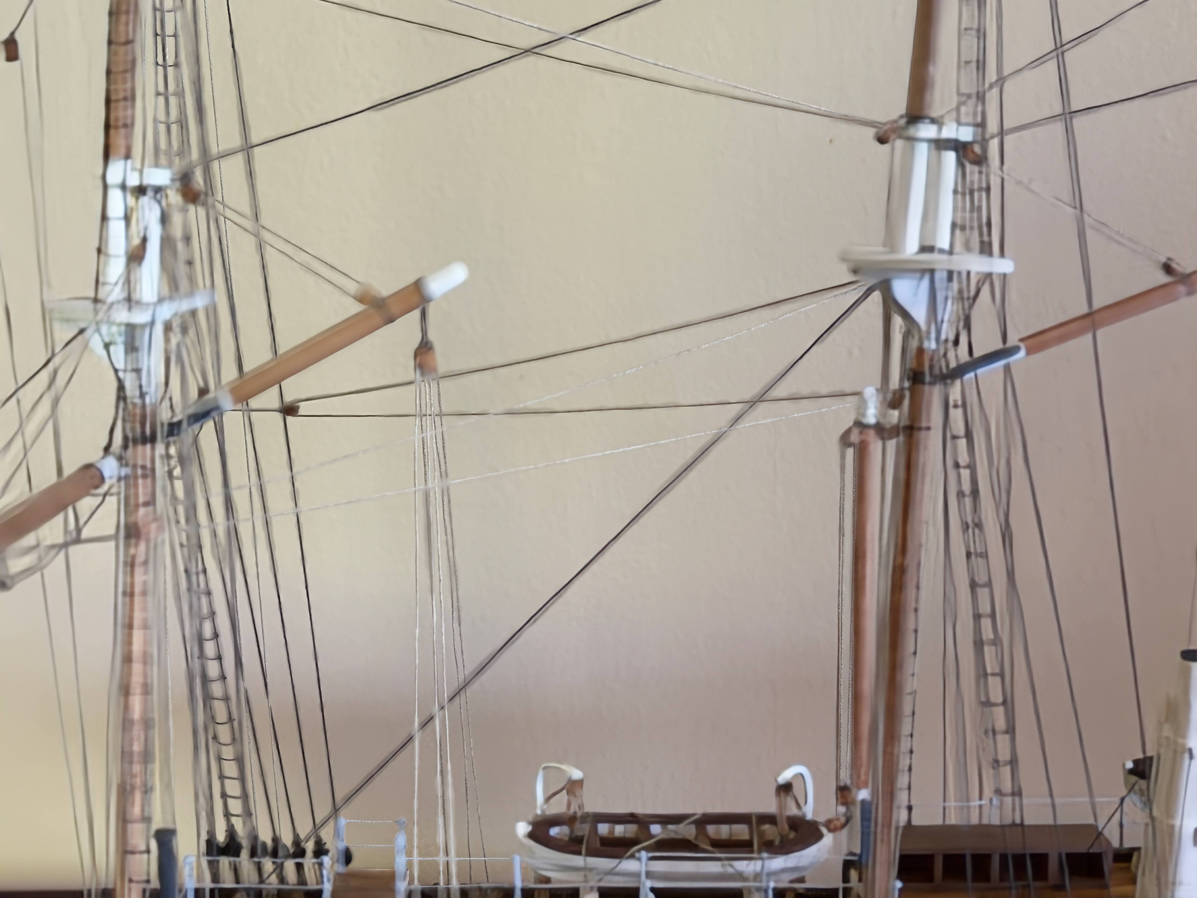
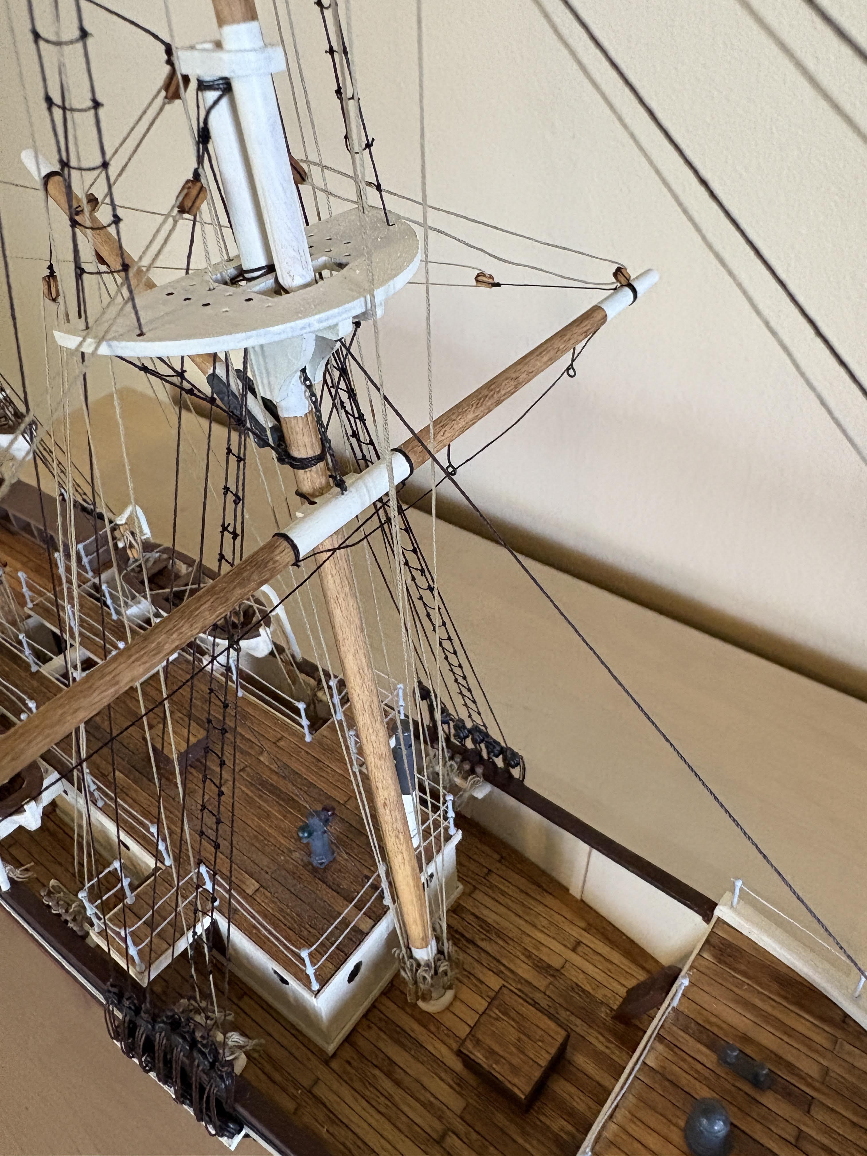
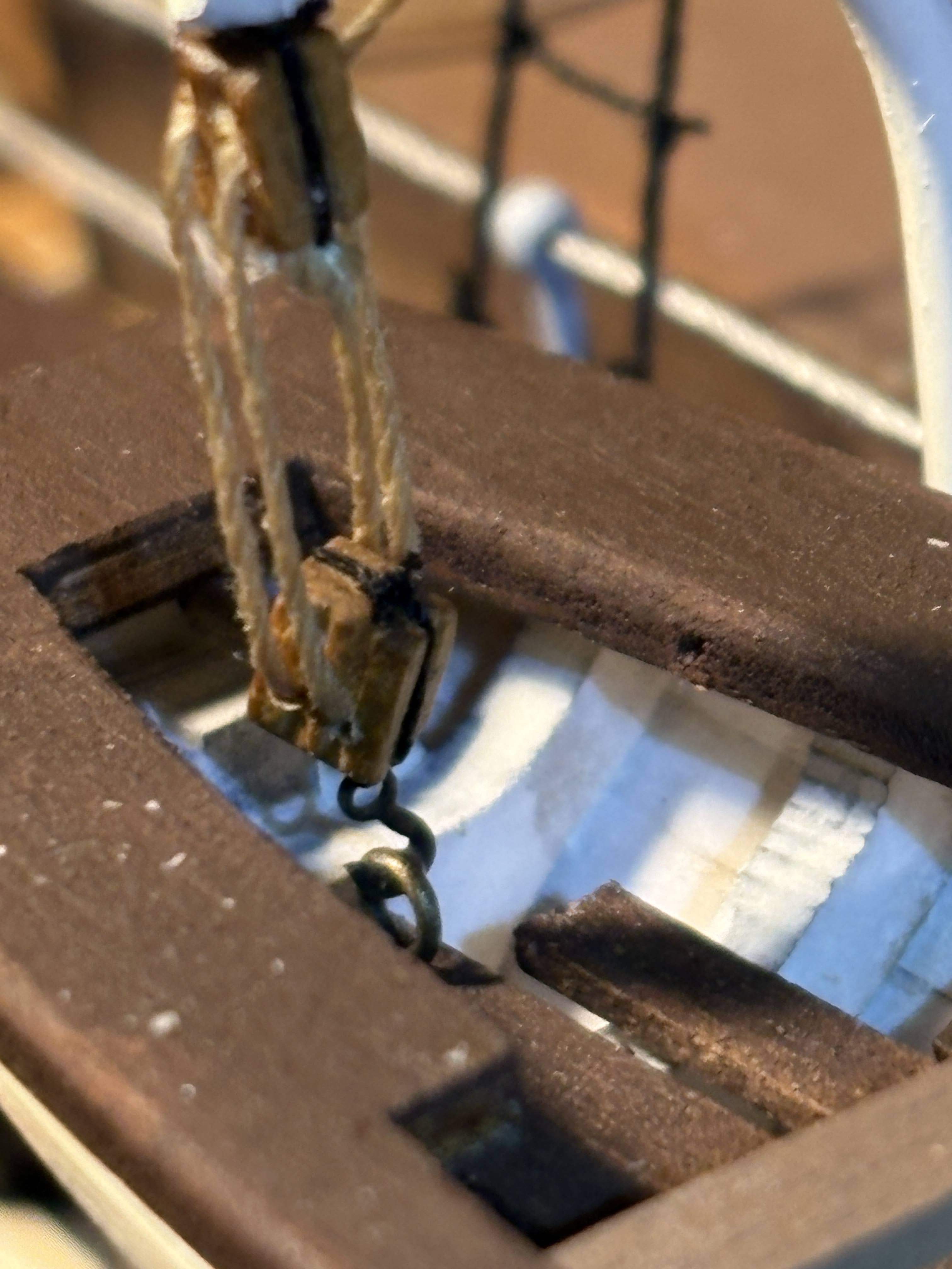
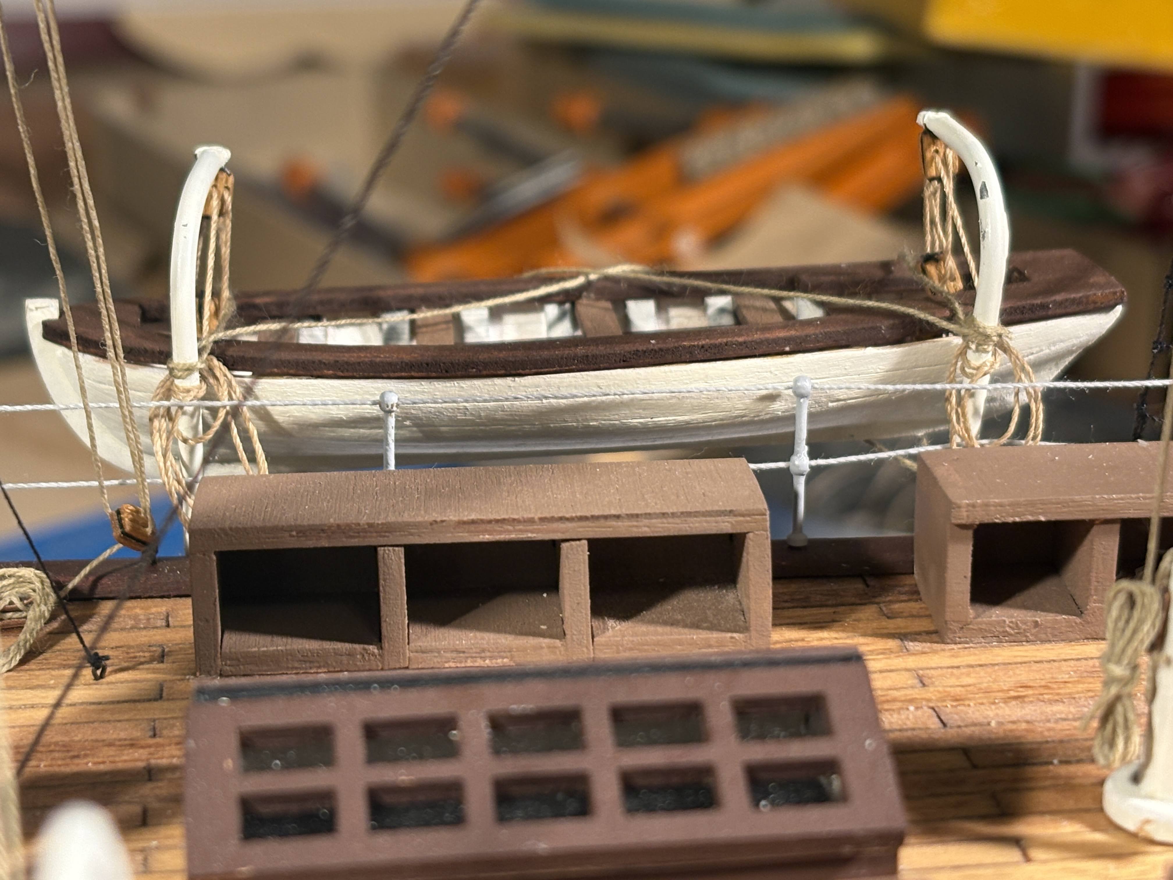
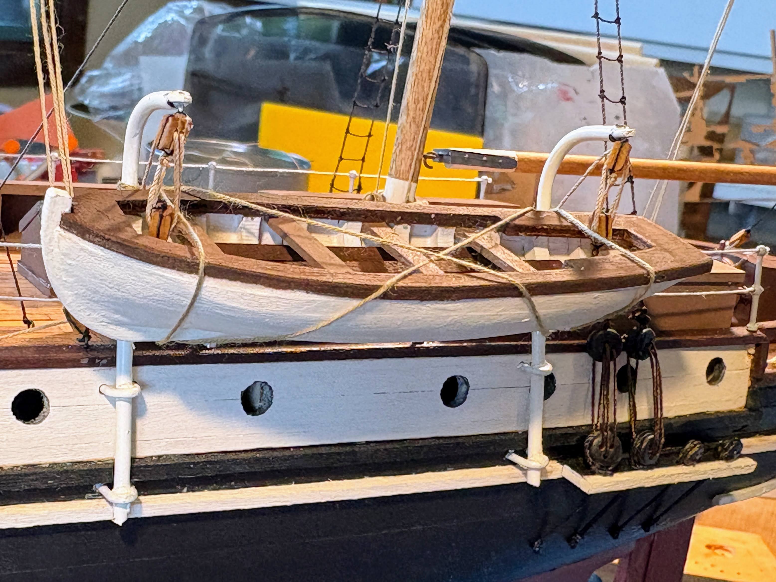
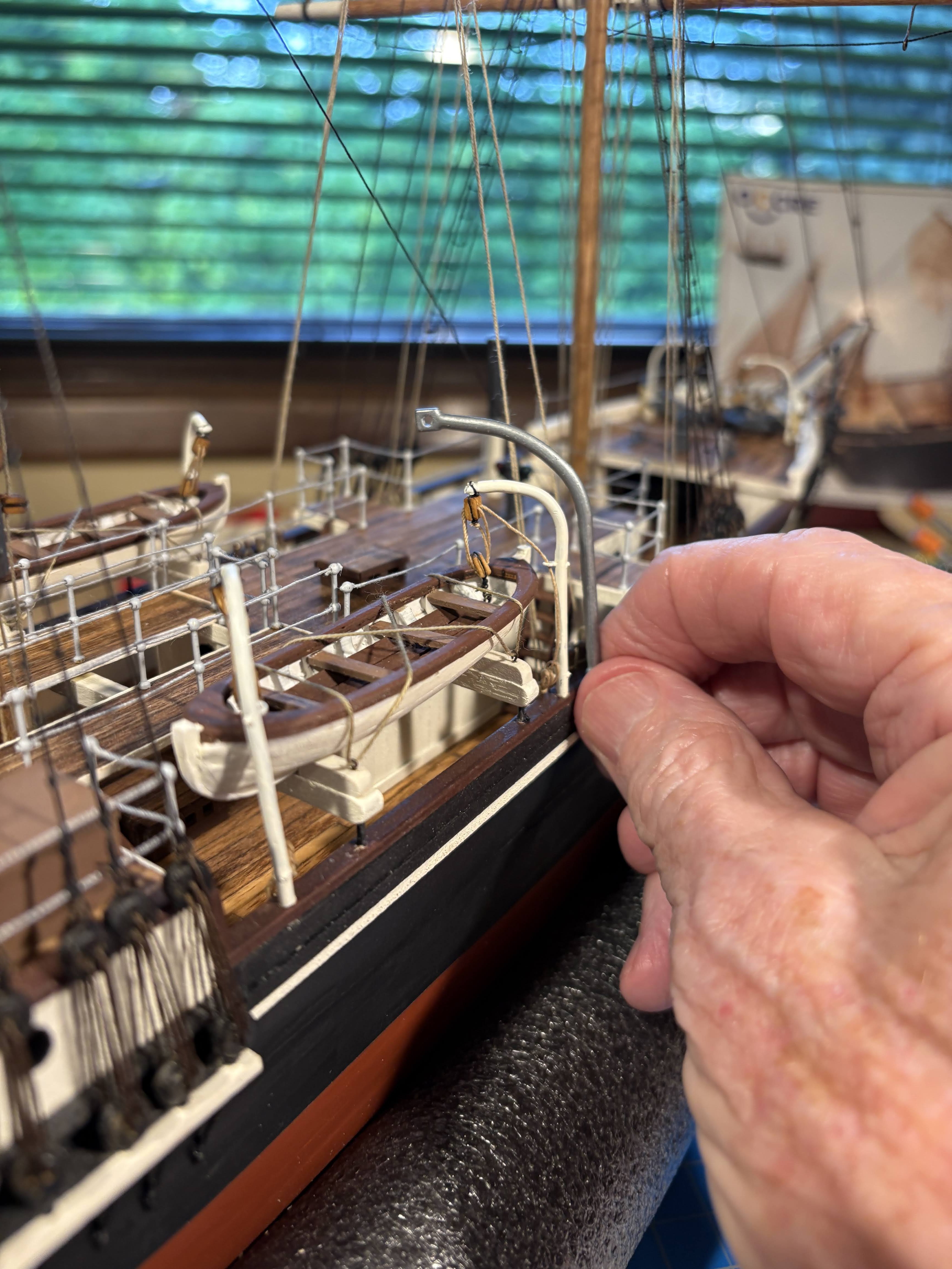
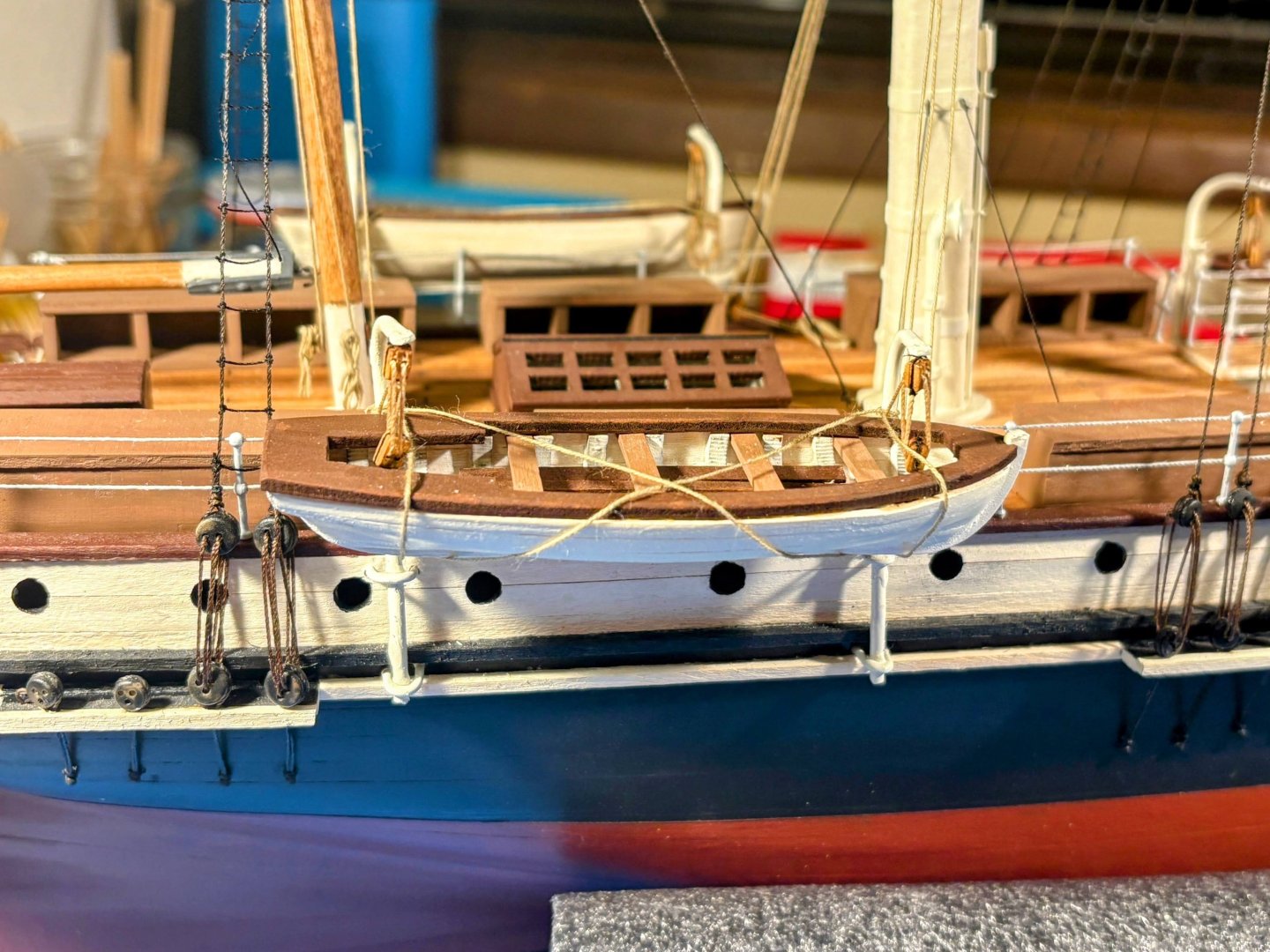
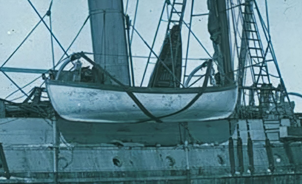
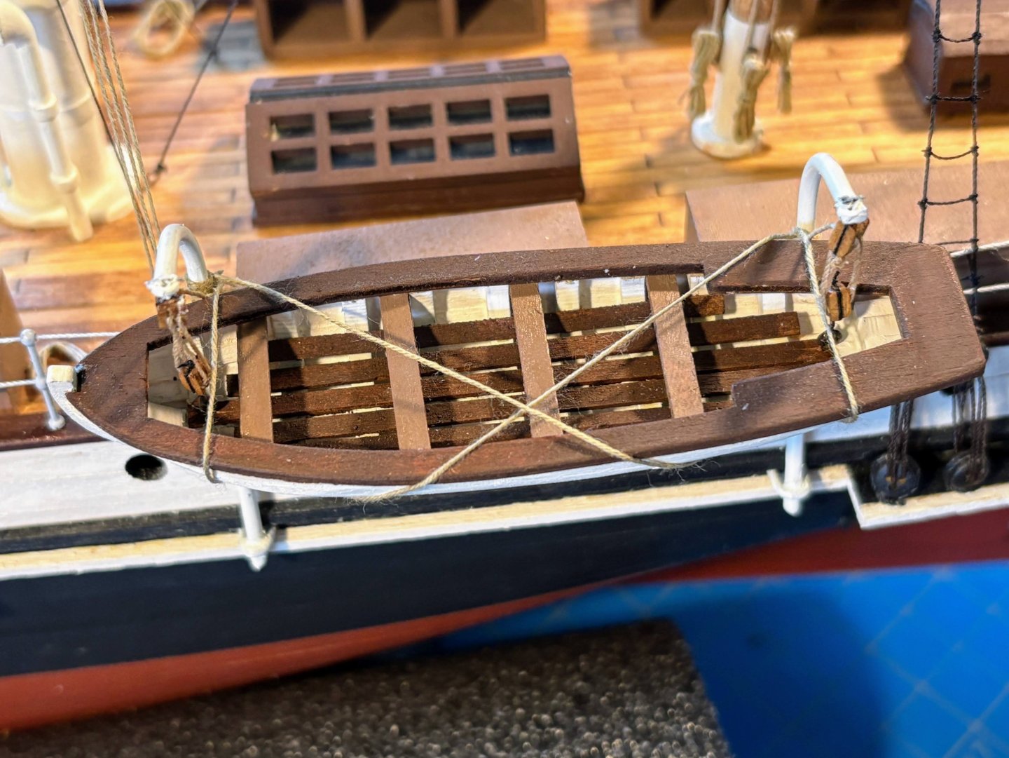
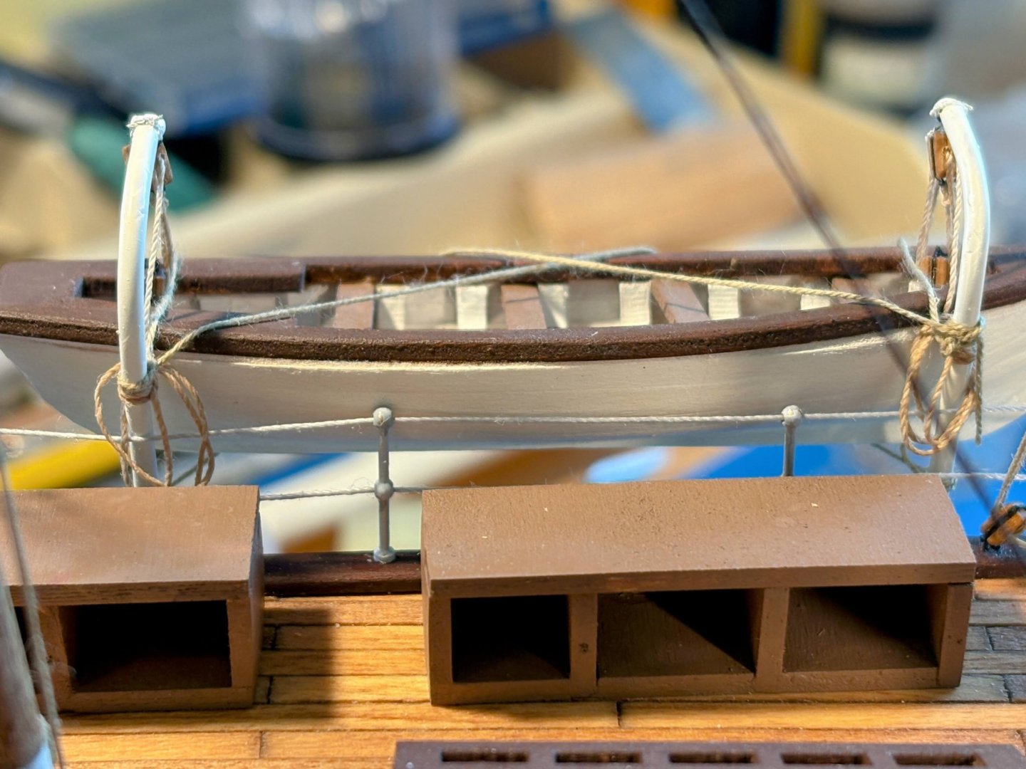
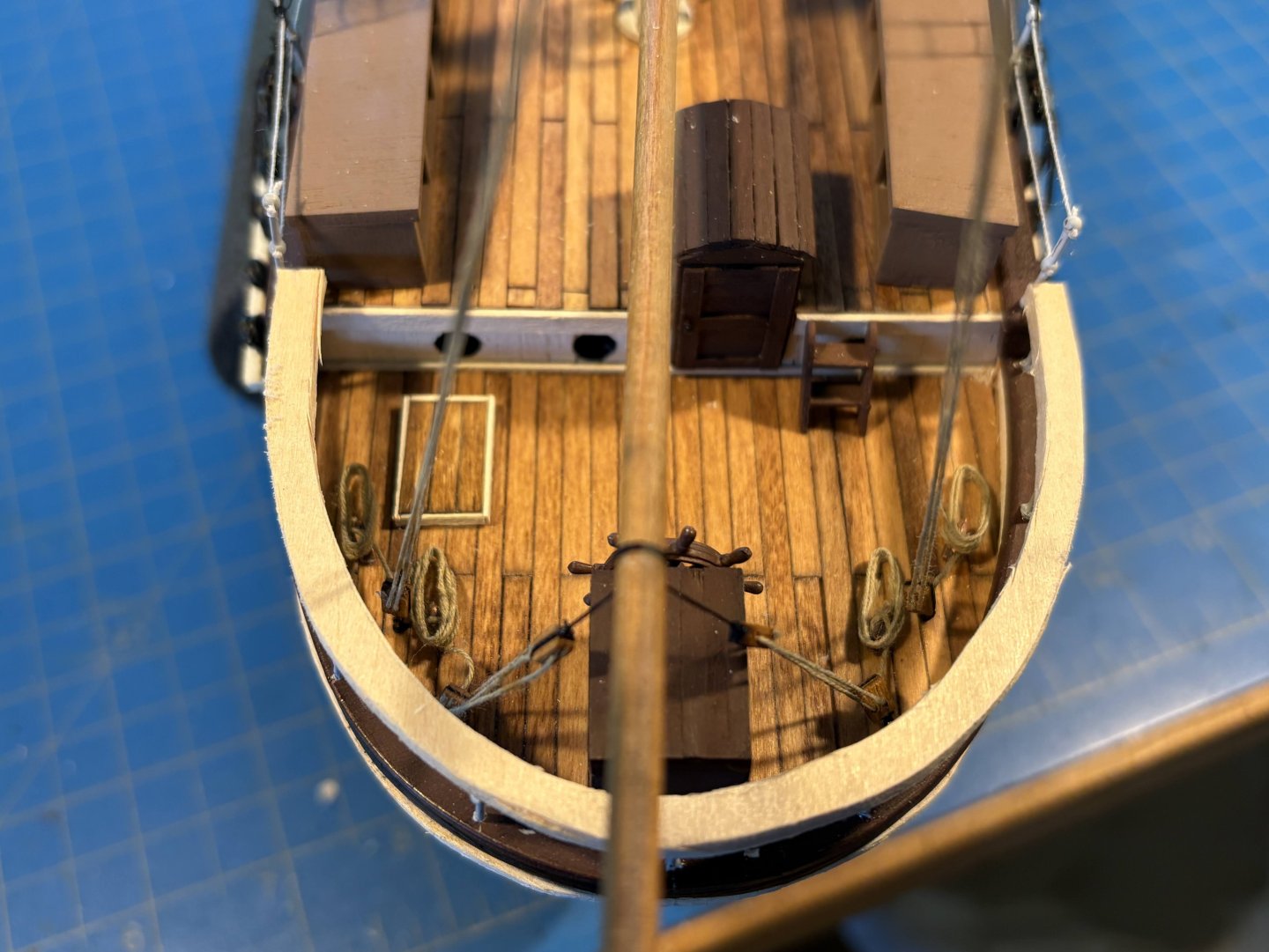
I don’t think I have seen any photos of the aft ship’s boats showing them anything other than hanging out over the water. In the photo below, it appears that the davits are not high enough to lift the boats over the railing and onto the deck. And once the dog kennels were added, there would be no room for the boats on deck. I made the davits the same way I made the forward boat davits, bending 2mm aluminum wire around a marker pen. This time I had to make fittings (or straps?) to wrap around the davits, attaching them to the sides of the hull. For this I used 1mm aluminum wire, the same material I used in making the anchor davits many months ago. After giving it some thought, I made the “legs” of these straps of unequal length, figuring I would insert the longer leg into its hole in the hull, then bend the fitting a minute amount as needed to get the other leg in its hole. Easier than trying to fit two legs into their holes simultaneously. In rigging the two tackles, I cut the thread too short; it would take quite a bit of rope to lower the boat into the water. I had too little thread to make a realistically robust rope coil, and I found it very difficult to coil what thread I had left to work with. In retrospect, I should have made separate rope coils from separate pieces of thread and fashioned something to hang them from, as I did with every other rope coil on the ship. As can be seen in the photo below, I had particular difficulty with the coil on the left. The saving grace is that these meager attempts won’t be all that noticeable in the overall scheme of things. And I’ve been giving some thought to a do-over, but haven’t quite gotten there yet. Now, I need to build the other boat and its davits. And finish the ratlines and some standing rigging on the mizzen mast. Who knows, maybe my next post will have “Finished” appended to the topic title. If so, it will likely be well into the fall before it’s posted.

- 206 replies
-
- 7
-
-
- Endurance
- Shackleton
- (and 2 more)
-
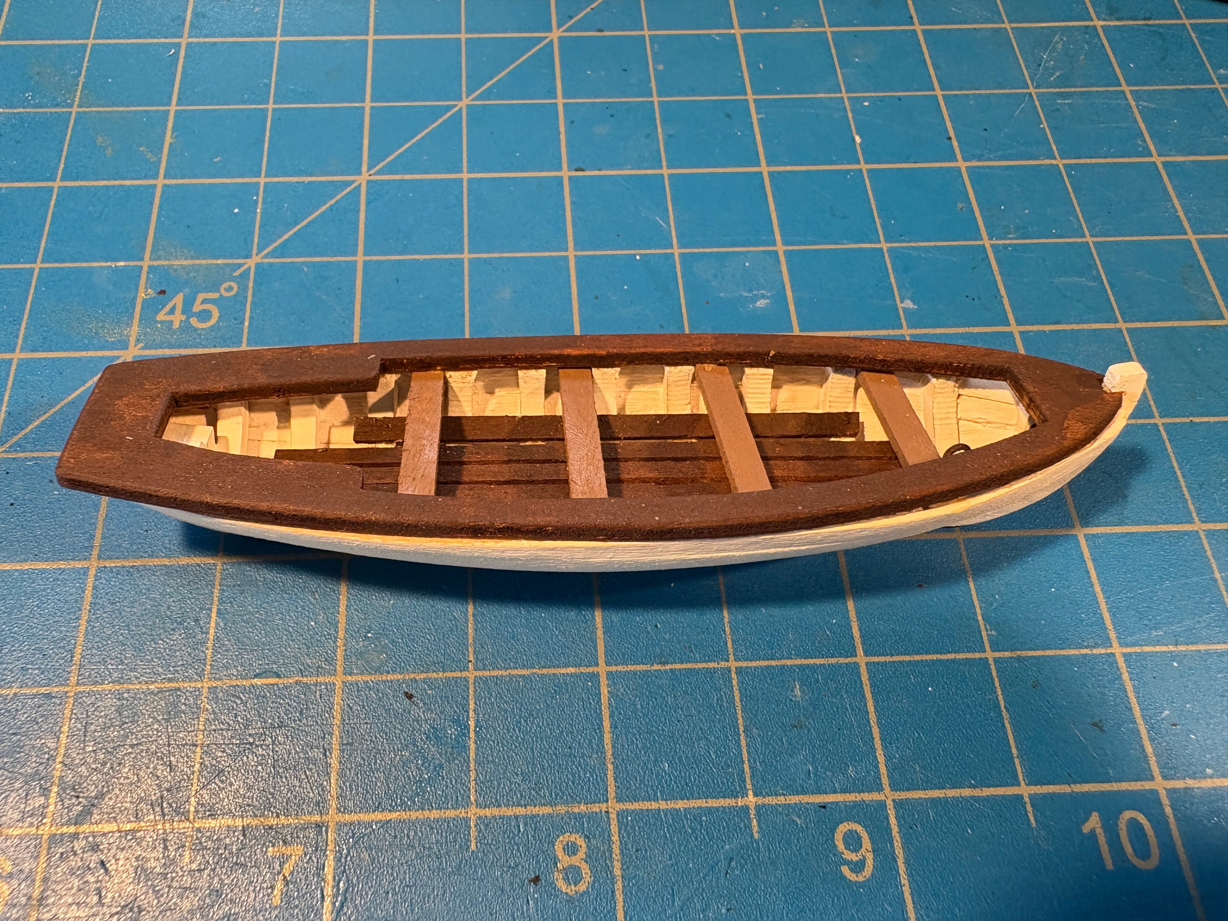
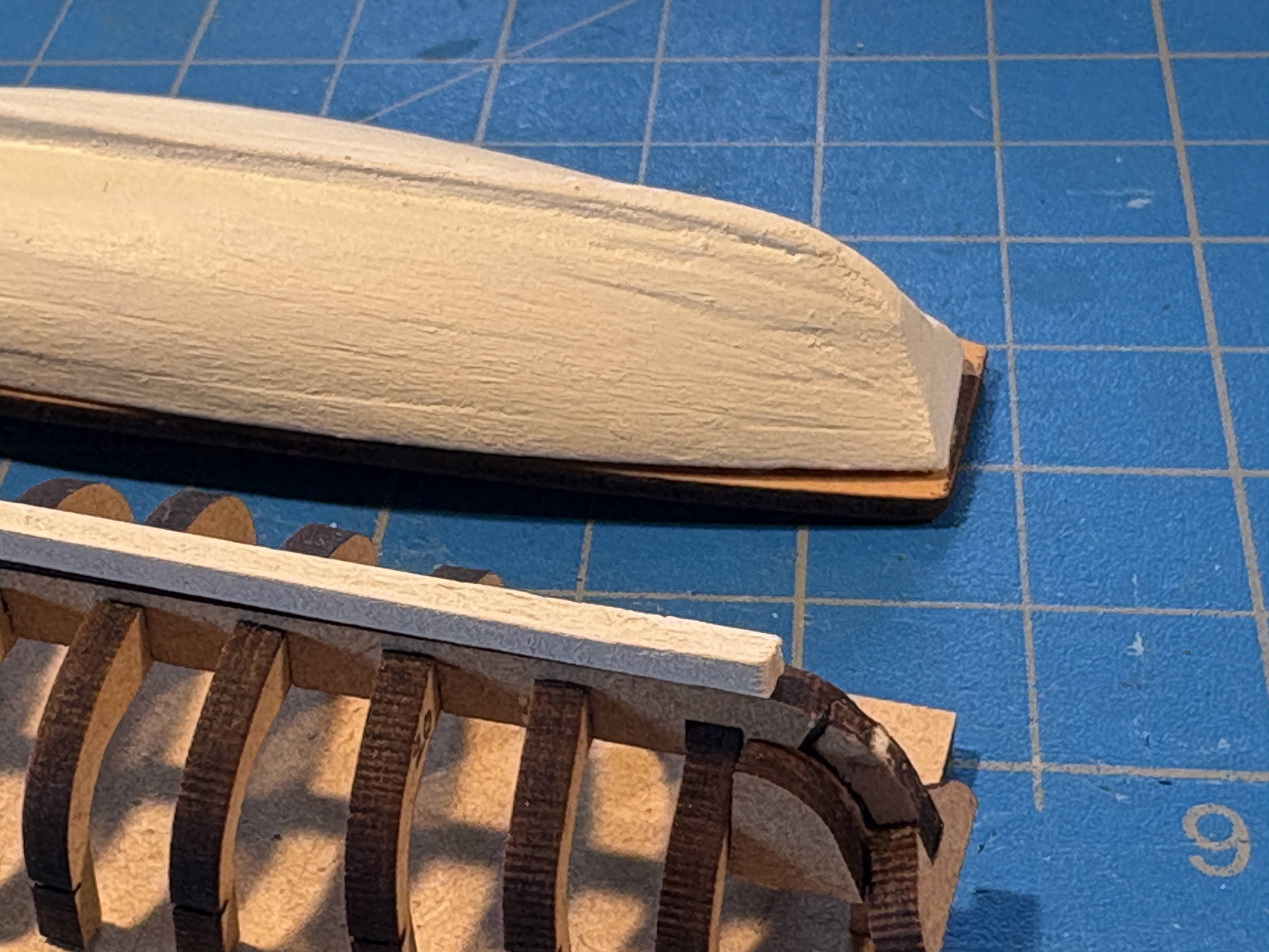
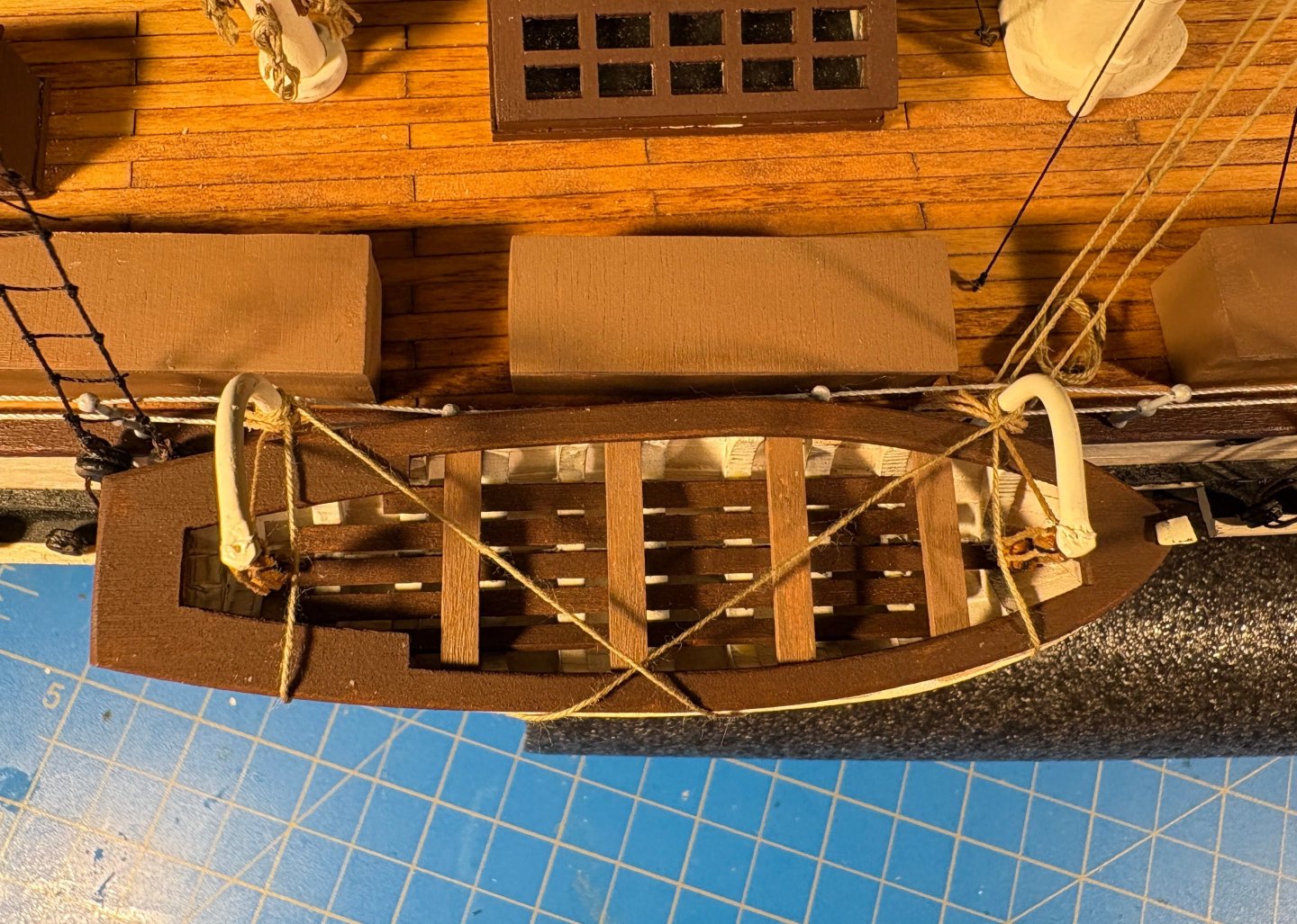
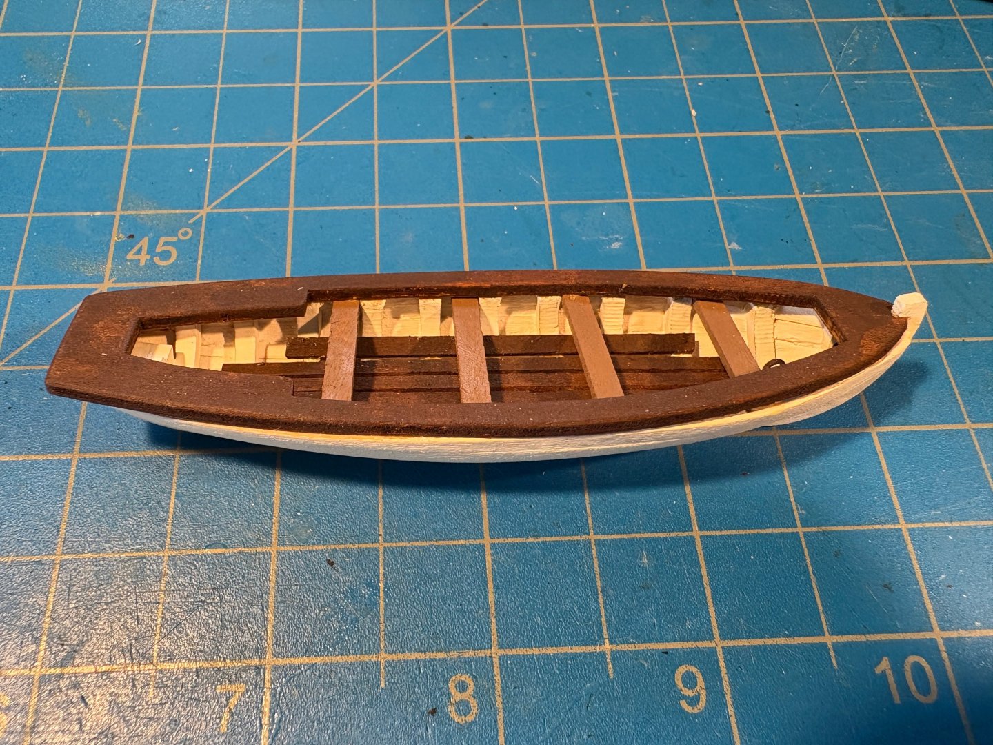
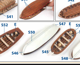
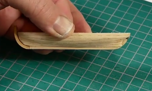
A month since my last post, and the only thing I have accomplished is building one of the two remaining ship’s boats. Ah, the joys of summer. As I mentioned in previous posts, these boats are larger than the ones I have already installed. Additionally they have a transom, while the others are double ended. The plans I have posted previously show none of them to be double ended and all to be about the same size. There is a mistake in OcCre’s instructions. The instructions show a piece (S47) butting up against the end of the keel (S50), while in actuality, that piece butts up against the transom at the upper end and the false keel at the other end. The aft end of the keel needs to be rounded or tapered to flow seamlessly into the false keel and piece S47. For me, the biggest challenge was shaping the sharp angle where the upper part of the hull, along the transom, meets the lower part, along the keel; a challenge mostly due to the small size of the boat. As is usually the case when I’m planking, things looked downright ugly before sanding and filling. 🙂


- 206 replies
-
- 4
-
-
- Endurance
- Shackleton
- (and 2 more)
-
A beautiful model and a job well done. Really looking forward to getting started with my Grecian, but I need to finish my Endurance first. It's getting close, but the distractions of summer have slowed work in the shipyard. Not that I'm complaining . . . Enjoy your next build. If my Endurance experience with OcCre is typical of their kits, the kit won't hold a candle to Vanguard. There will be lots of opportunities for kit bashing, which I found enjoyable.
-
Most (if not all) of us who have posted logs for Ernest Shackleton’s Endurance have posted photos of the real ship, mostly photos taken by Frank Hurley, who was a member of the crew. After reading several articles about Fair Use and copyrights, I’m quite confident that using such photos on this site does not violate any such rights. But I’m no expert, and as @ccoyle has pointed out, we’re not just dealing with federal law but also MSW and NRG interests and policies. While wrestling a bit with those issues, I found something very interesting. Many of the Endurance photos have been collected and are now for sale on the Getty Images website. While Getty Images was founded by a member of the Getty family, it is a for profit business organization, completely separate and independent from the magnificent Getty Museum, which is owned and operated by a non-profit, tax exempt organization. Buried deep on the Getty Images website I found the following, at https://www.gettyimages.com/faq/working-files Using images for free The images on Getty Images are intended for use in commercial and editorial projects. This means you need to buy a license to use the image in most projects, including personal use. You can use an image without paying for a license with our Embed feature, which lets you use over 70 million photos on any non-commercial website or blog (if you're using it to sell a product, raise money or promote or endorse something, Embed isn't for you). In other words, you can post their images on “any non-commercial website or blog” for free. That is much simpler and easier to comply with than the Fair Use rules. The following page tells you more about free use of their photos and how to do it using their “Embed” feature: https://www.gettyimages.com/resources/embed I did that about an hour ago for my most recent post on my Endurance blog. I think they want you to use "Embed" because the process filters out those photos that aren't among the 70 million that are free. Once you've done that, I assume it’s equally free if you simply copy a filtered photo on the website, paste it where you save photos, and drag it to your post as you would for any photo you had taken yourself.
-
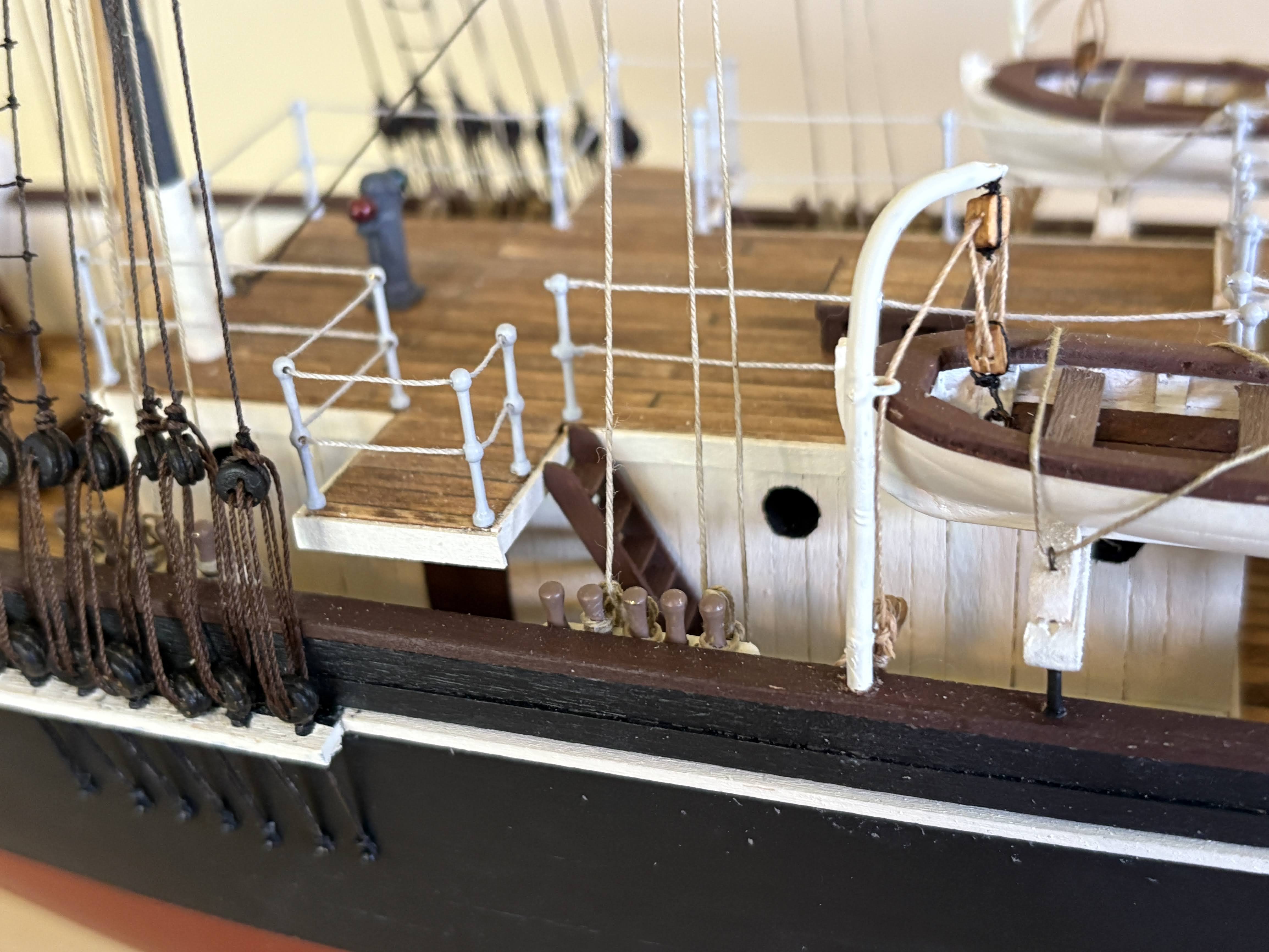
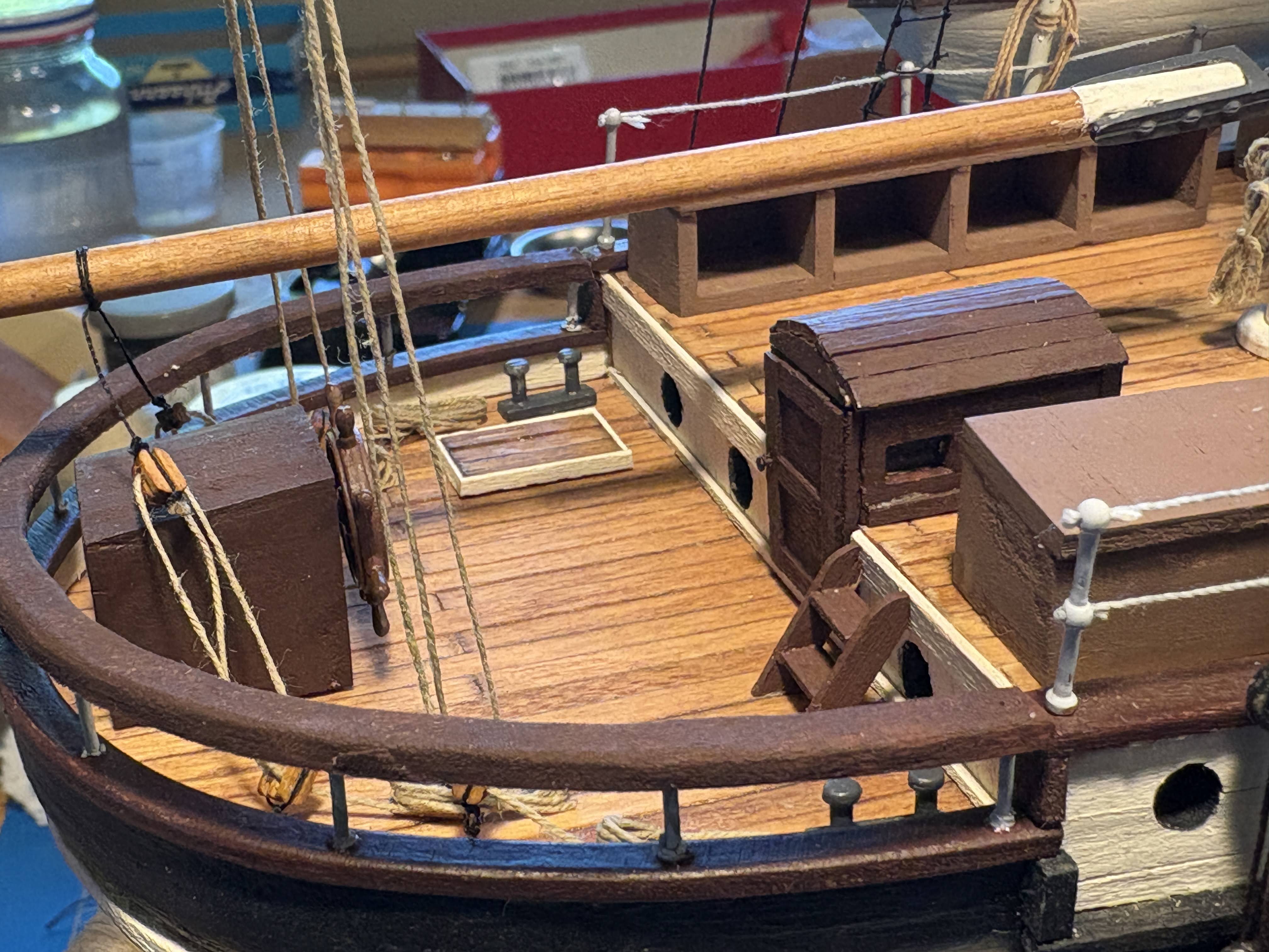
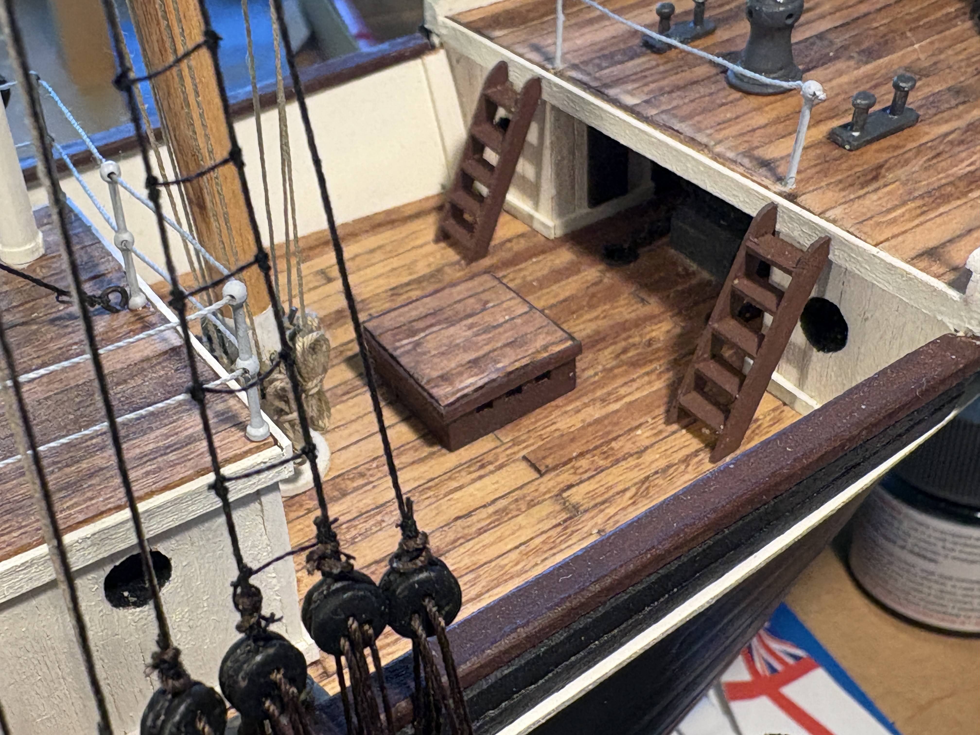
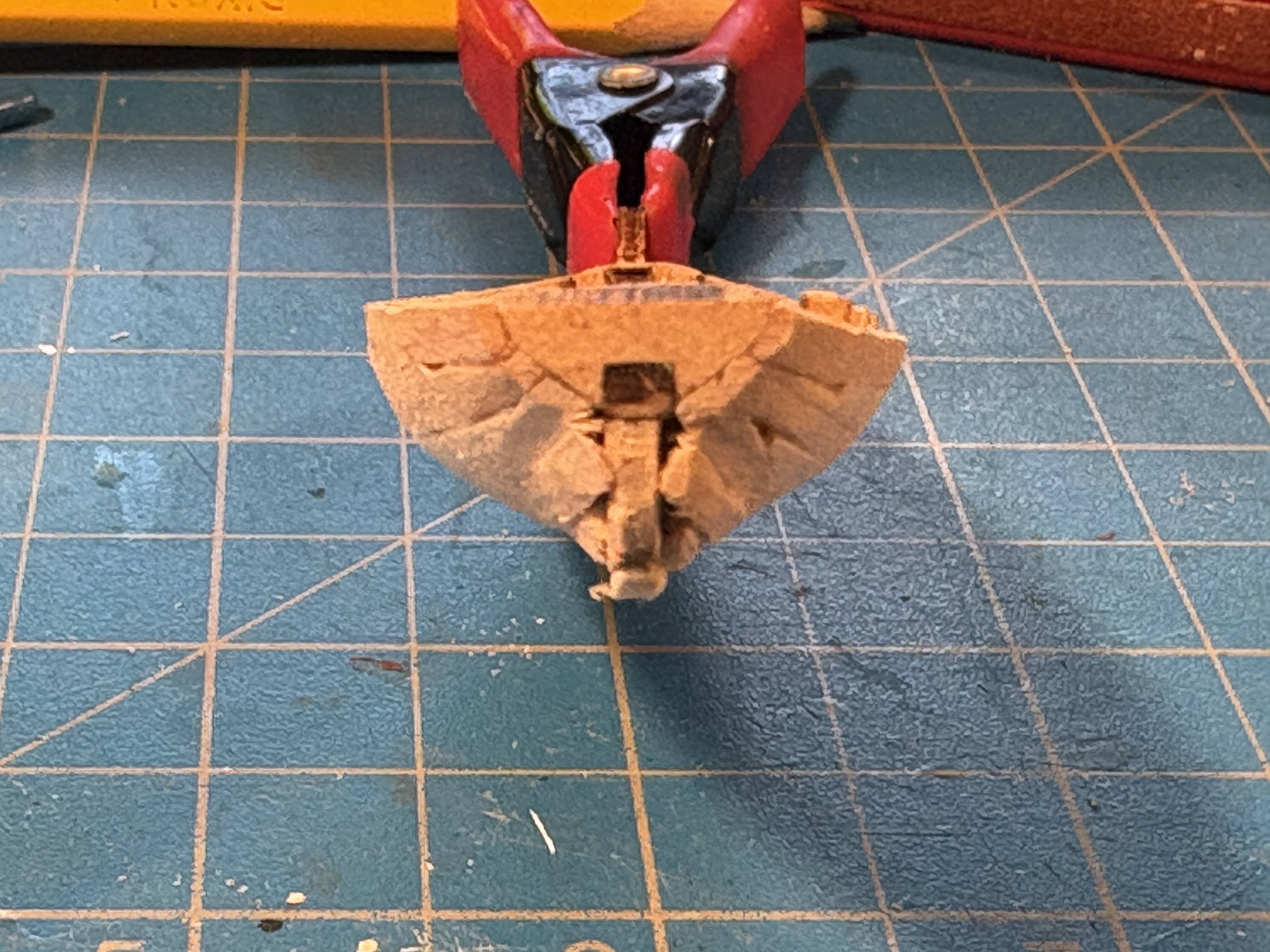
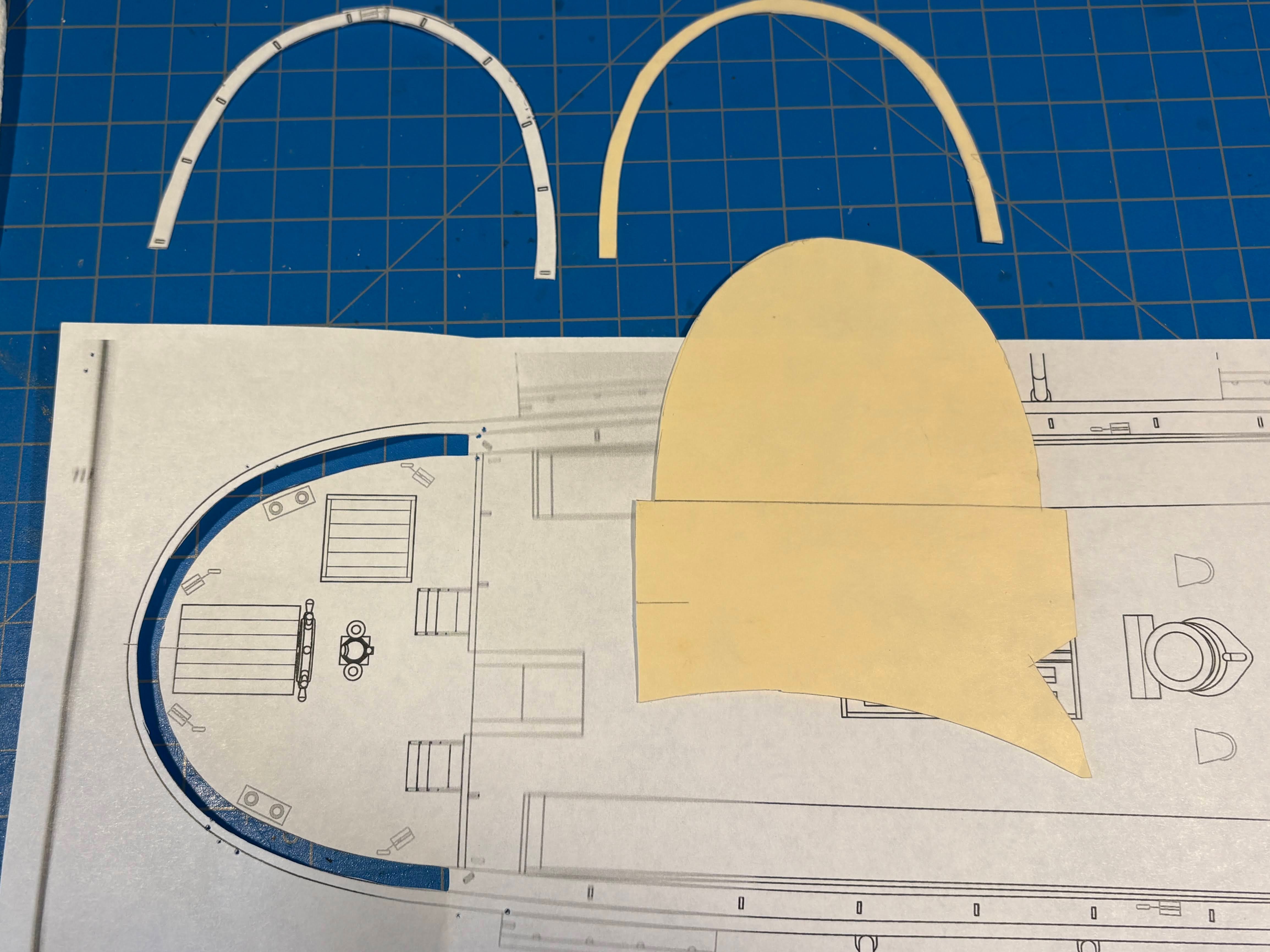
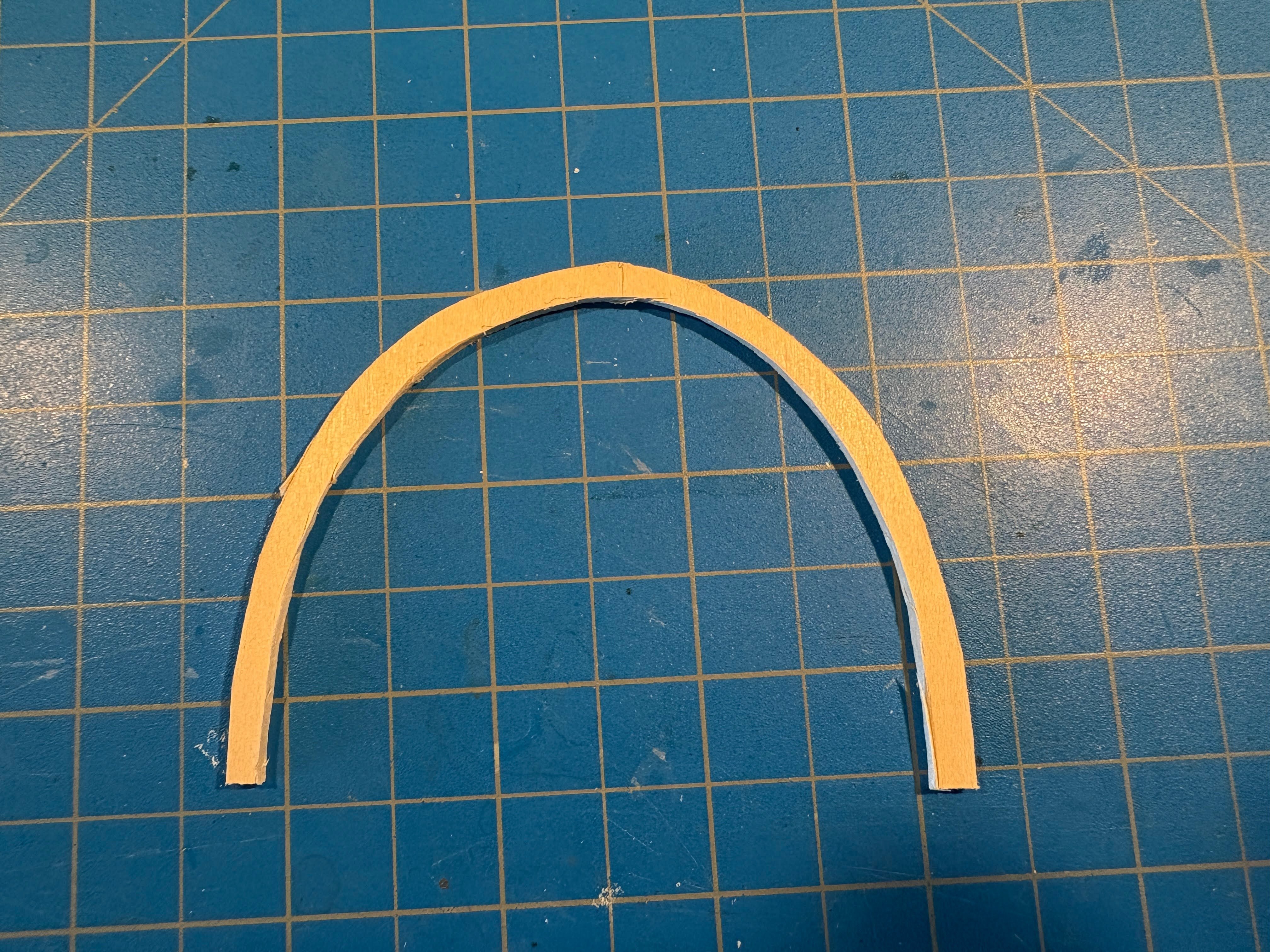
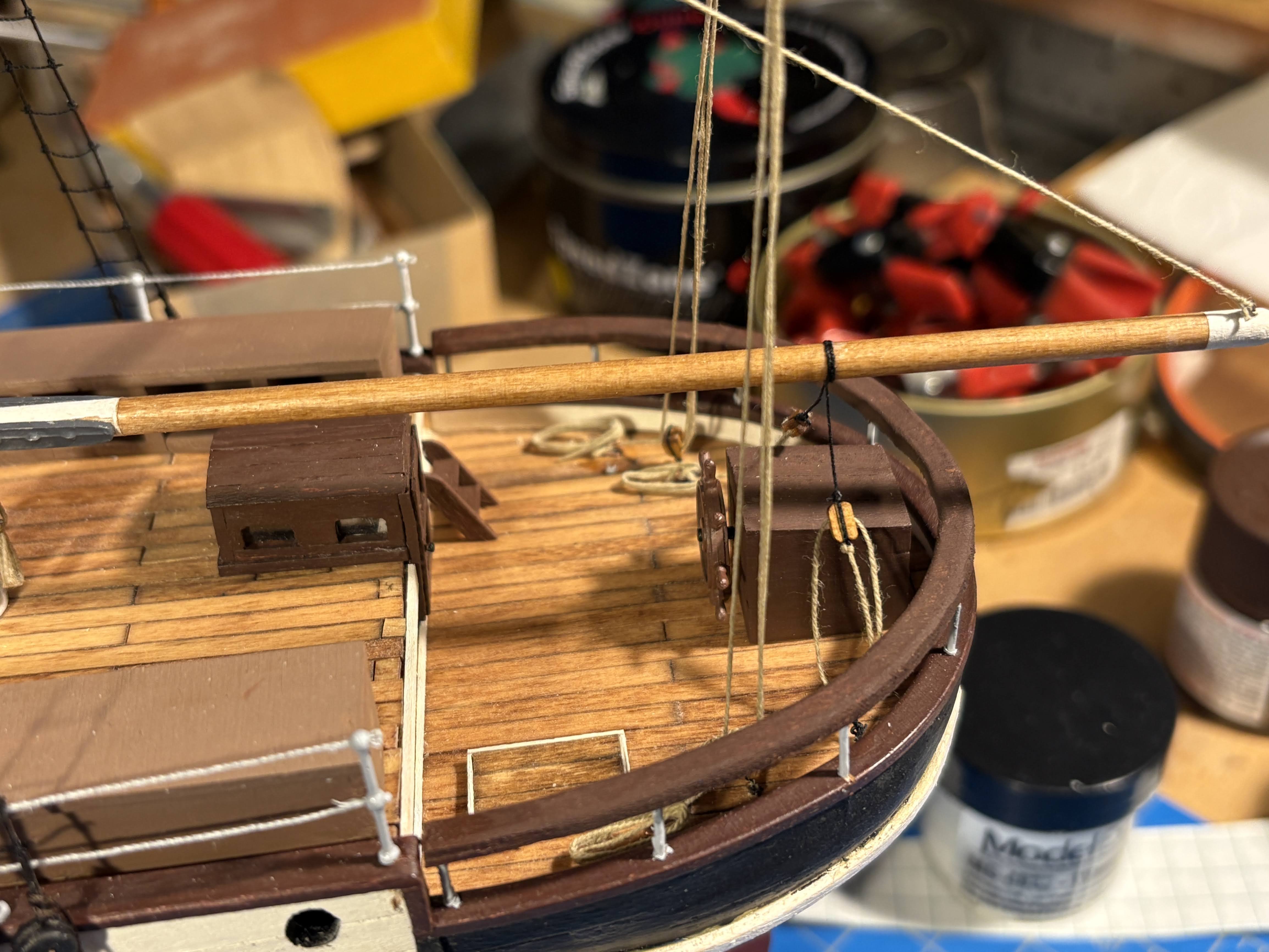
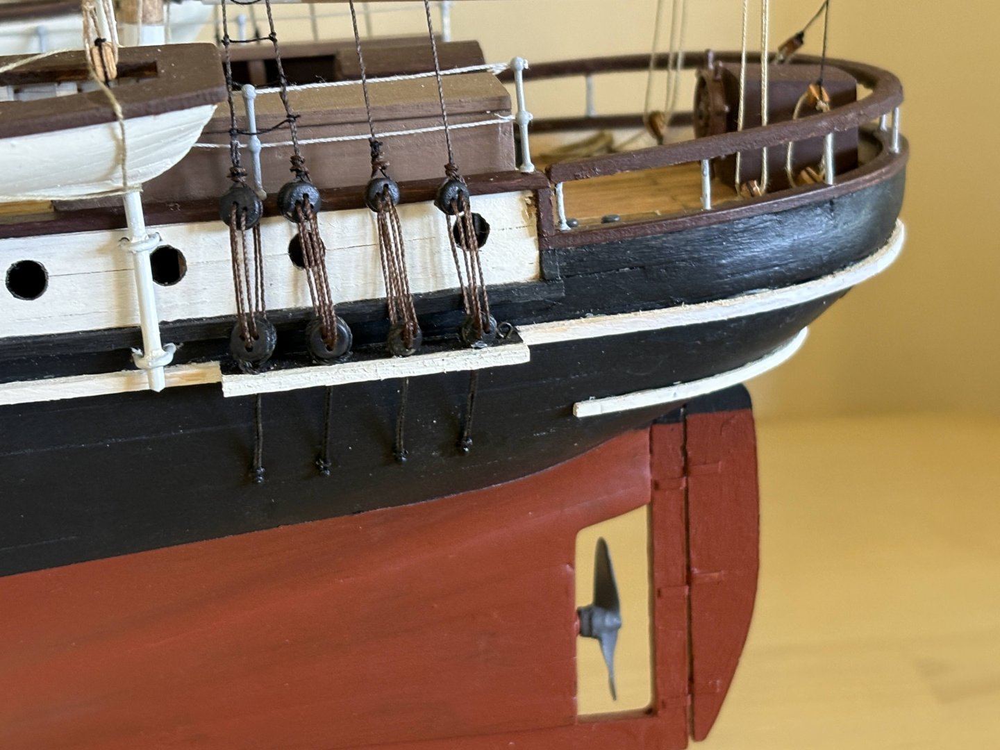
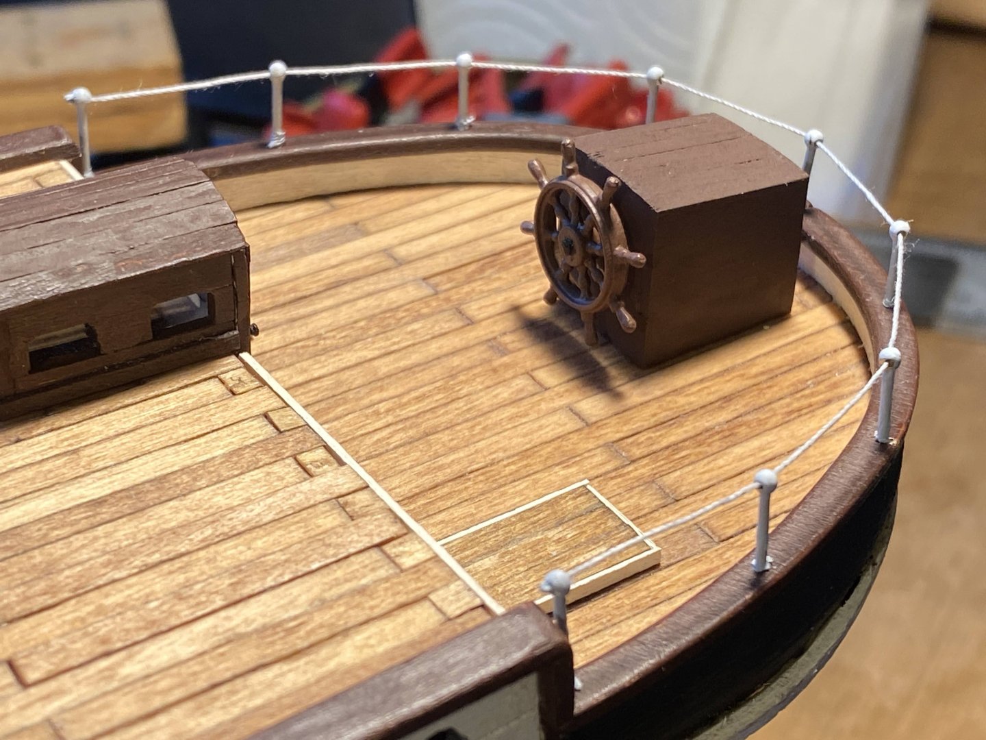
Thanks for the kind remarks Mark. I had some fun putting the boats and davits together. About a year ago, I installed railings on deck, using realistic looking brass stanchions I ordered online from somewhere instead of the flat photo-etched ones supplied by OcCre. I Installed the railing that runs around the stern as instructed by OcCre (the railing topped by a cable), and later remembered a photo of the ship which shows a wooden cap atop the railing. Ever since then I have thought about a do over to make my model better match the real thing, but that thought was always accompanied by another thought . . . I’ll approach the issue another day. Well, another day has arrived. Once I decided that the do over was in fact doable, I photo-copied the aft deck plan included in OcCre’s instructions, then cut out the rail, intending to use that as a template, to make sure the fit was right and for cutting out the rail from a sheet of 3/32” basswood I had. The paper was too flimsy to use for checking the fit, so I used it to cut a template from something thicker (an old file folder). I then cut out the rail using an Xacto knife. The result was a little asymmetrical, but I was hopeful that wouldn’t show. Laying it on top of the stanchions allayed my fears in that regard, but I discovered it was a couple of millimeters too narrow at the open end of the horseshoe. Fortunately it could be pulled to the appropriate width without stressing the wood much at all. The point of no return came when I clipped off the tops of each of the stanchions. That took some courage, but I grit my teeth, held my breath, and did it. To stretch the rail cap to the desired width, I drilled holes in each end and slipped them over the stanchions. Getting holes precisely drilled for all the other stanchions was going to be a challenge, so instead I tried leaving a drop of CA on top of each of the remaining stanchions and simply laid the rail cap on top of the rest of them. That worked better than I expected. I’m sure it’s a little fragile, but that’s true of most of any ship model. Unfortunately the rail cap is a bit too thick (I later found a 1/16” sheet that would have been better), but over all I’m pretty happy with the result. Finally, I have now glued the dog kennels in place.


- 206 replies
-
- 3
-
-
- Endurance
- Shackleton
- (and 2 more)
-
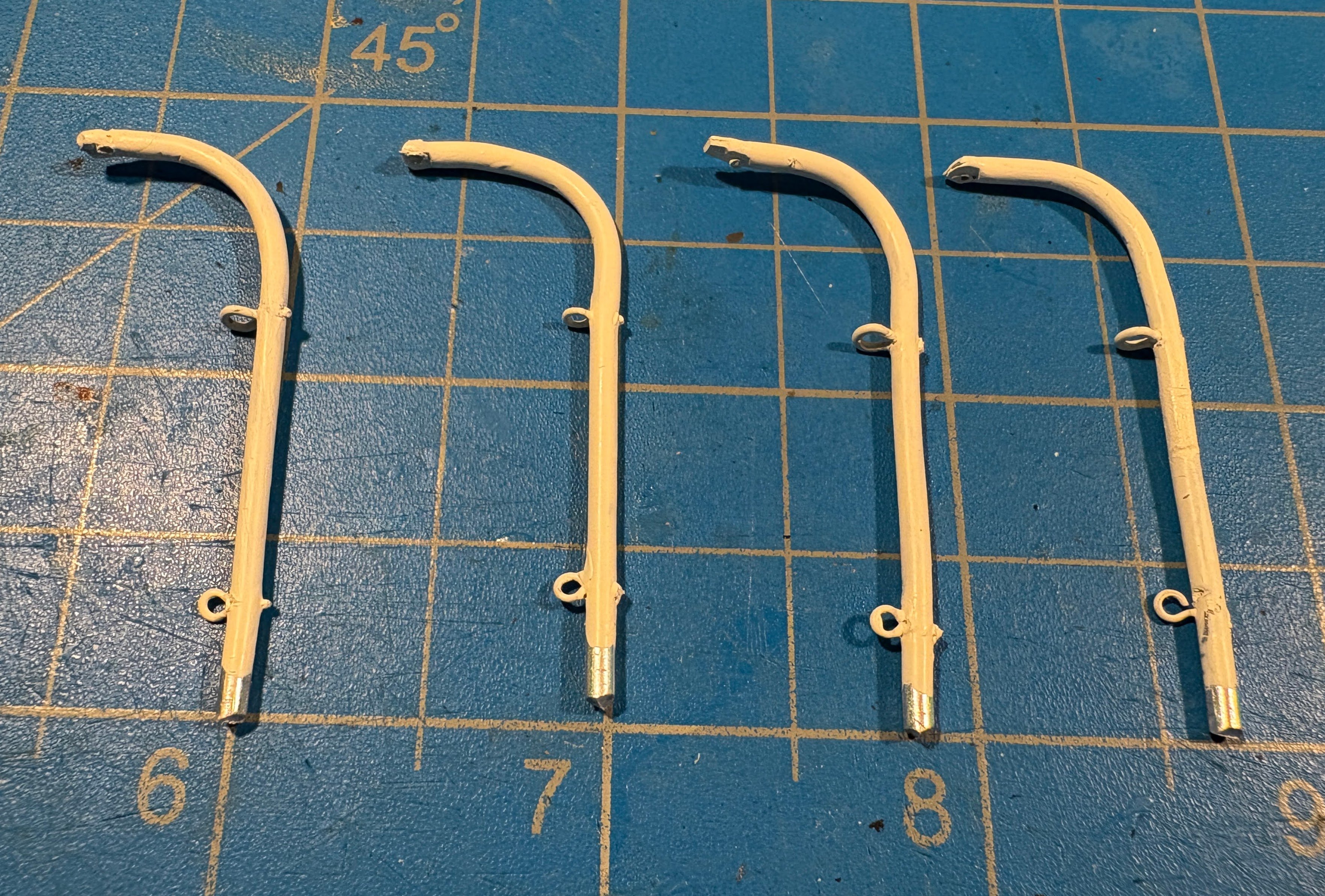
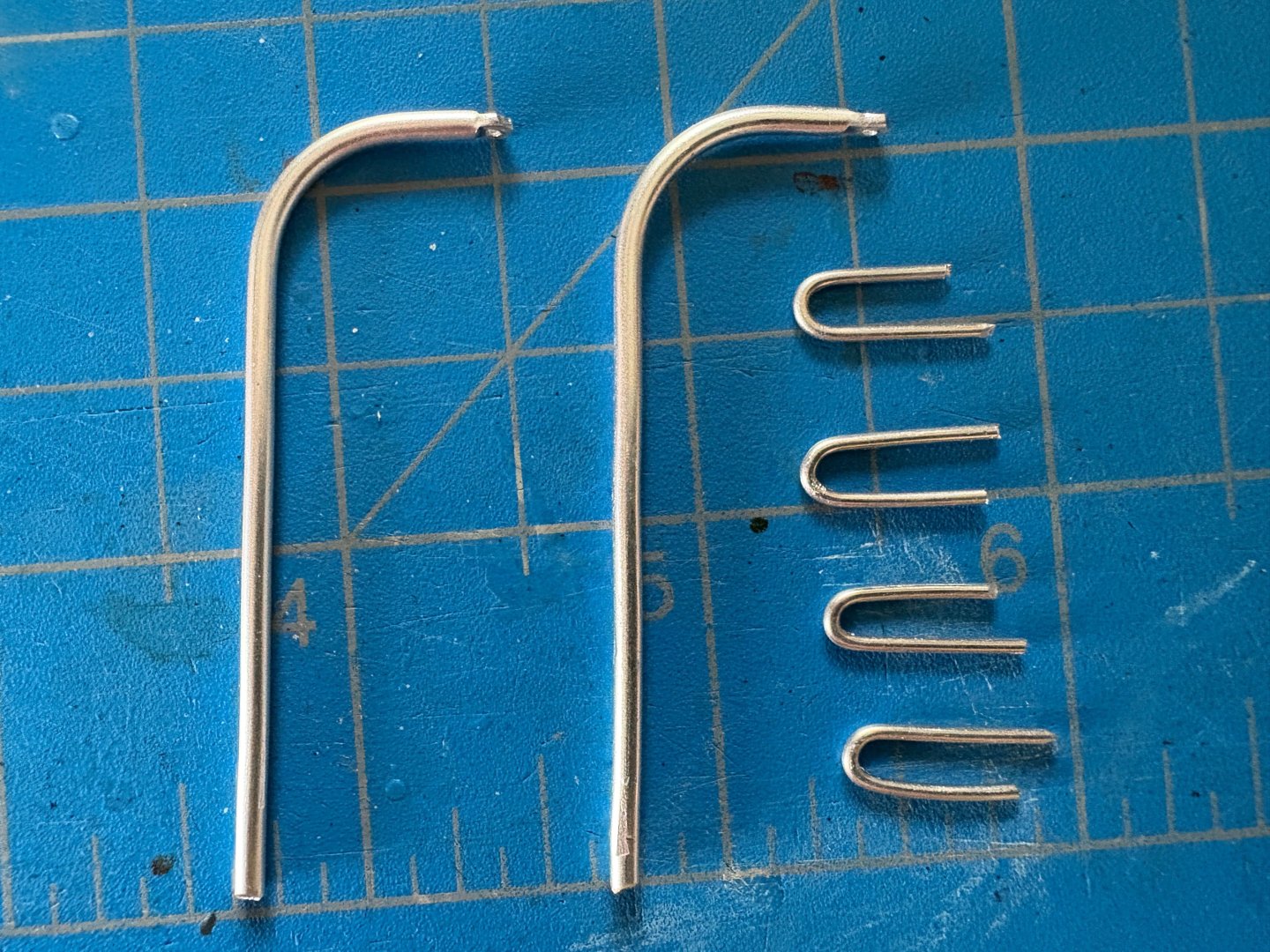
A year ago March I made anchor davits from some 1mm aluminum wire that I had lying around. It was very easy to bend and otherwise work with, and I had no idea where it came from. Some Google sleuthing revealed that it’s often used in crafts, which led to the realization that this wire was probably something our daughter played with probably more than 25 years ago. That wire was too thin to work for these davits, but I found some 2mm wire online that worked just fine. At least for these two boats, the davits supplied by OcCre not only don’t work facing inboard, but IMHO they are too large for this scale. Bending this wire to the desired shape was quite easy. I found a highlighting pen that made a perfect jig. I then used some blunt nosed pliers to flatten the upper end of each wire and put a hole in each one to attach the tackle to. The latter proved to be far more difficult than I expected; in part because my mini drill bit set is not very good quality, and in part because flattening the ends probably made the aluminum harder and denser. The problem I had was creating enough of an indentation so that the drill bit didn’t dance all over the place before finally digging into the aluminum. What finally worked was driving a tiny nail through the metal, and enlarging the hole with an appropriately sized bit. Then I realized that the tackle couldn’t travel in a straight line to a cleat positioned where any crew member could reach it; it would drape against the side of the boat, which just didn’t look right. So I drilled holes for small eyebolts for the line to pass through. I don’t have, and probably couldn’t reliably handle, blocks small enough to fit the bill. Next challenge was making cleats for securing the end of the tackle, very much like the wire cleats I attached near the bottom of each mast. The masts of course are significantly larger in diameter than these davits, and they provided a much better gluing target than these davits. After an hour or two of unsuccessful efforts, I gave up and decided another eyebolt would have to serve as a faux cleat. Next step was to give the assembled davits a bath in denatured alcohol to get any finger grease off of them (I kind of guessed that was a good idea), then painted them with the same Model Shipways “Warm White” paint that I used on everything else that is white on the ship. Rigging the tackles was pretty straight forward. As with the anchor tackles, I used photo-etched hooks (left over from my prior build) to attach the tackles to the eyebolts previously installed in each boat. Those hooks are all but invisible in the photos below. Tying off the running end of each tackle was pretty straightforward as well. Far more challenging was hanging a rope coil on each eyebolt rather than on a cleat; it took quite a bit of effort for something that is almost not visible. A dab of white paint on the top of each davit hides the thread used to tie the upper blocks to the davits.


- 206 replies
-
- 3
-
-
- Endurance
- Shackleton
- (and 2 more)
-
You are doing a superb job on Grecian, and I'm going to start following your build closely. My kit arrived a couple of weeks ago, but it will be some time before I get started on it. I need to finish Shackleton's Endurance, and I also have the NRG's half hull project waiting. One question I have . . . since you have painted and copper plated the hull, what purpose did your second planking serve? I asked the same question of others who were working on Endurance, didn't get a convincing response, and decided to forgo the second planking. The first planking required a lot of filling and sanding (you did a good job of that on yours), but I was as happy with the painted result as I would have been had I done a second layer of planks. Maybe I'm just lazy . . .