Tomculb
-
Posts
346 -
Joined
-
Last visited
Content Type
Profiles
Forums
Gallery
Events
Everything posted by Tomculb
-
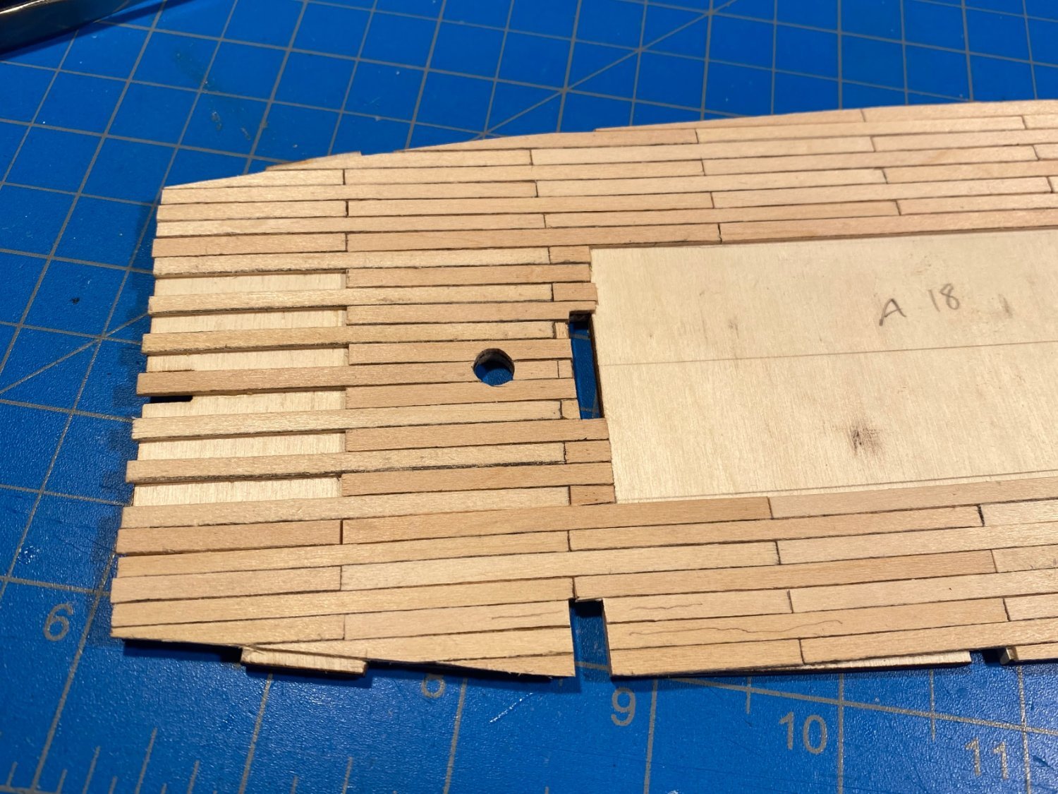
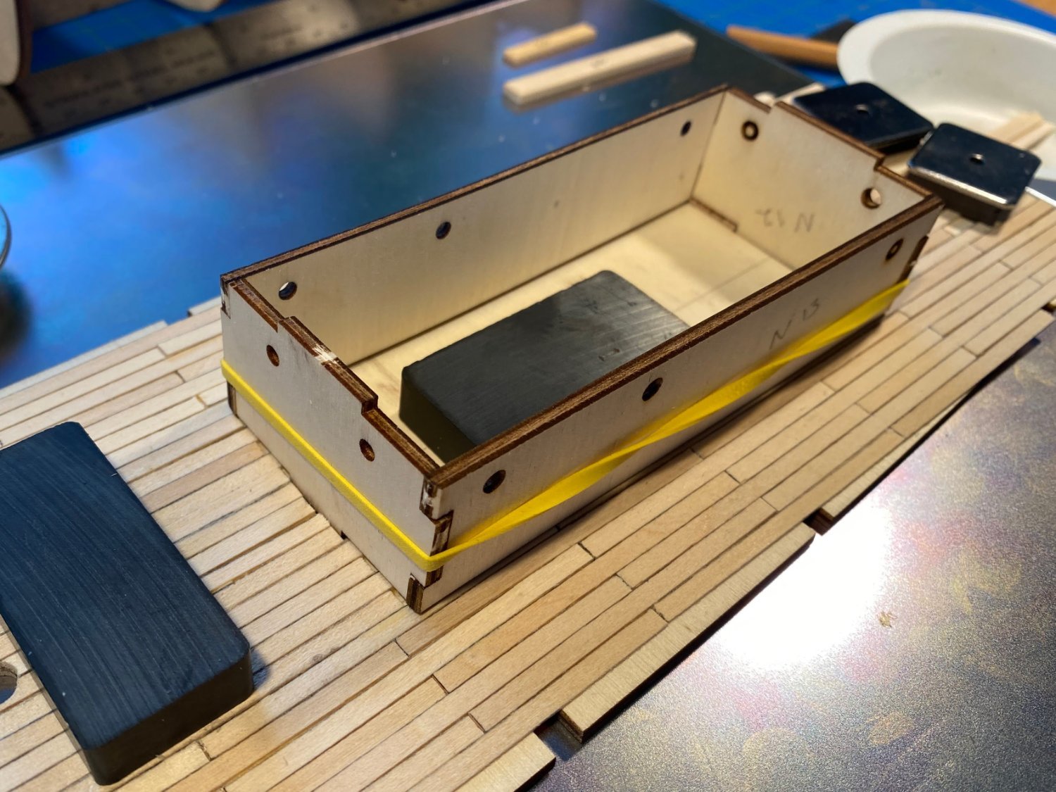
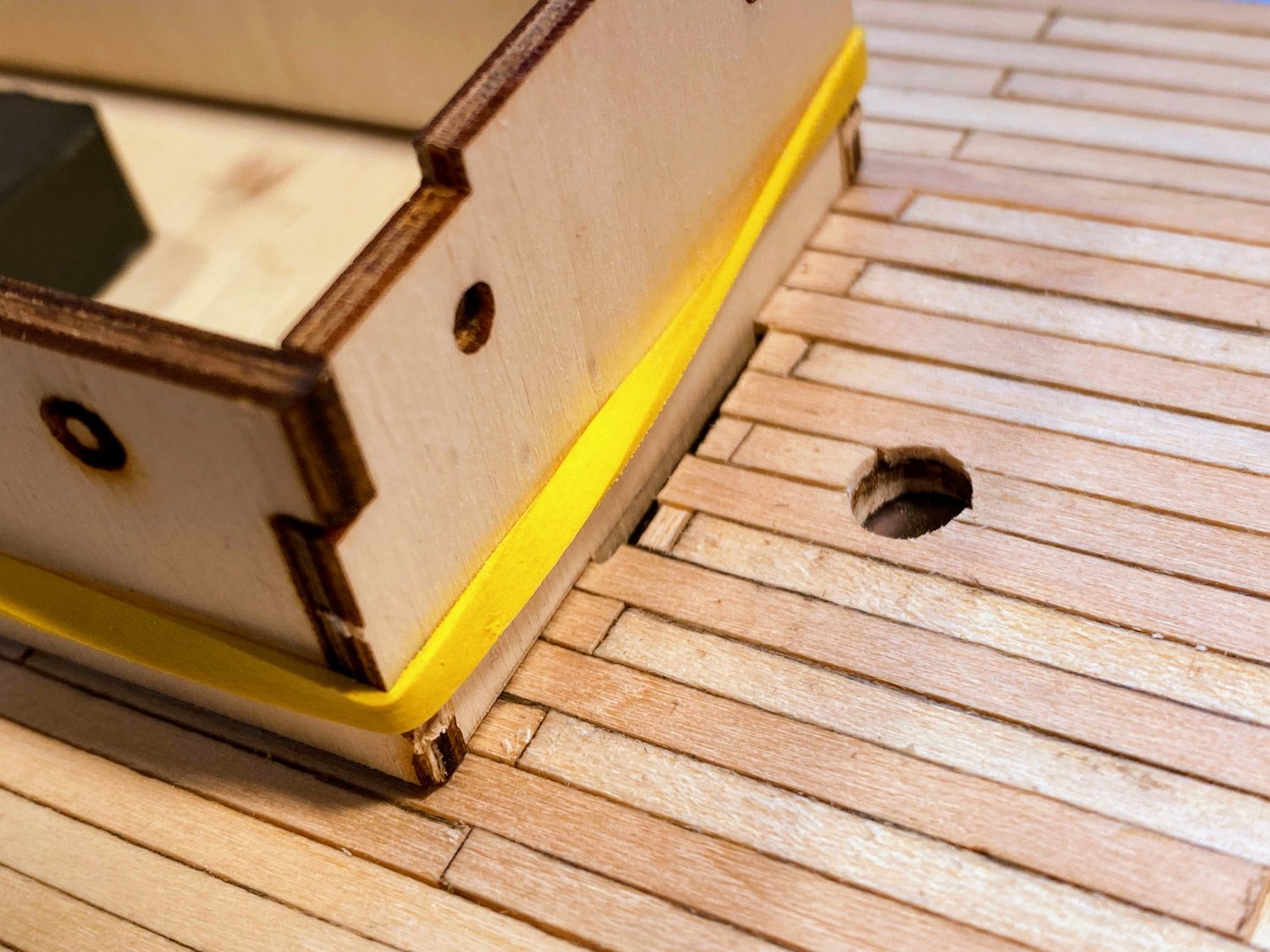
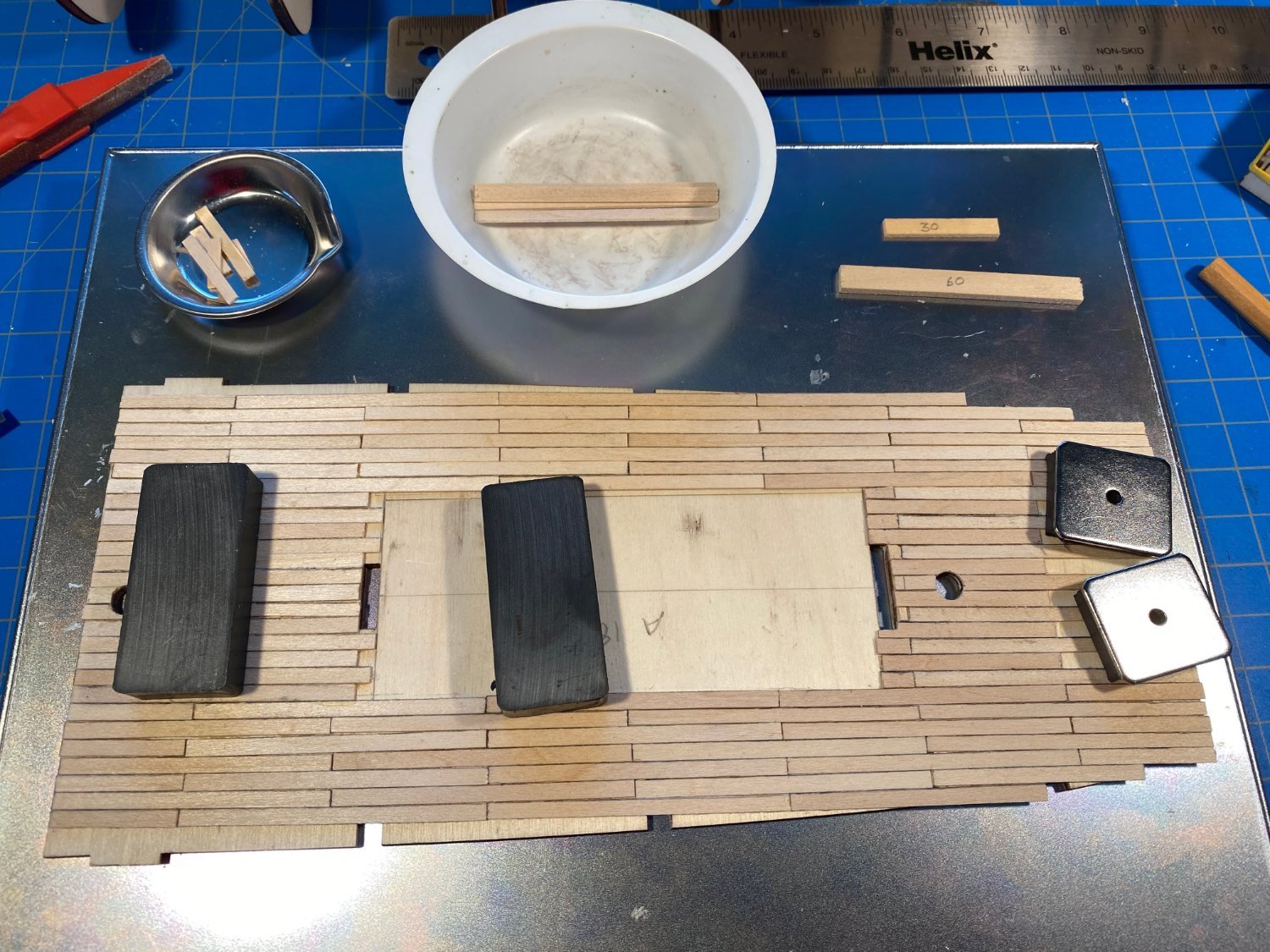
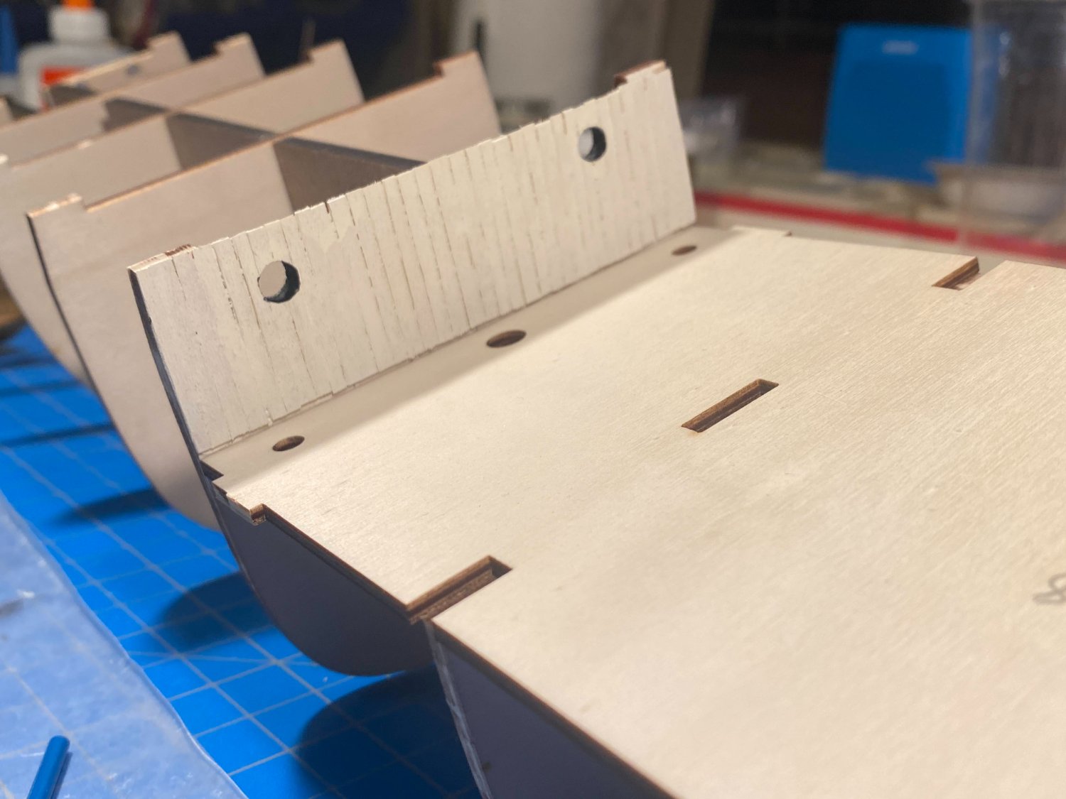
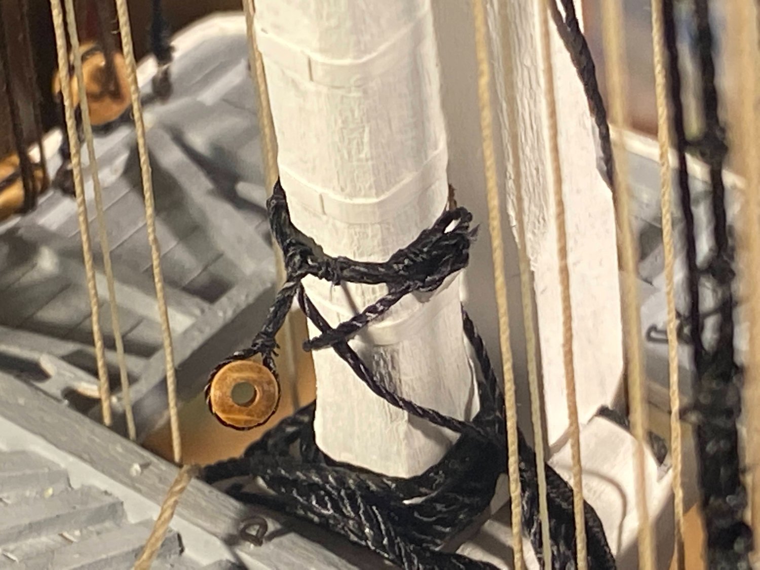
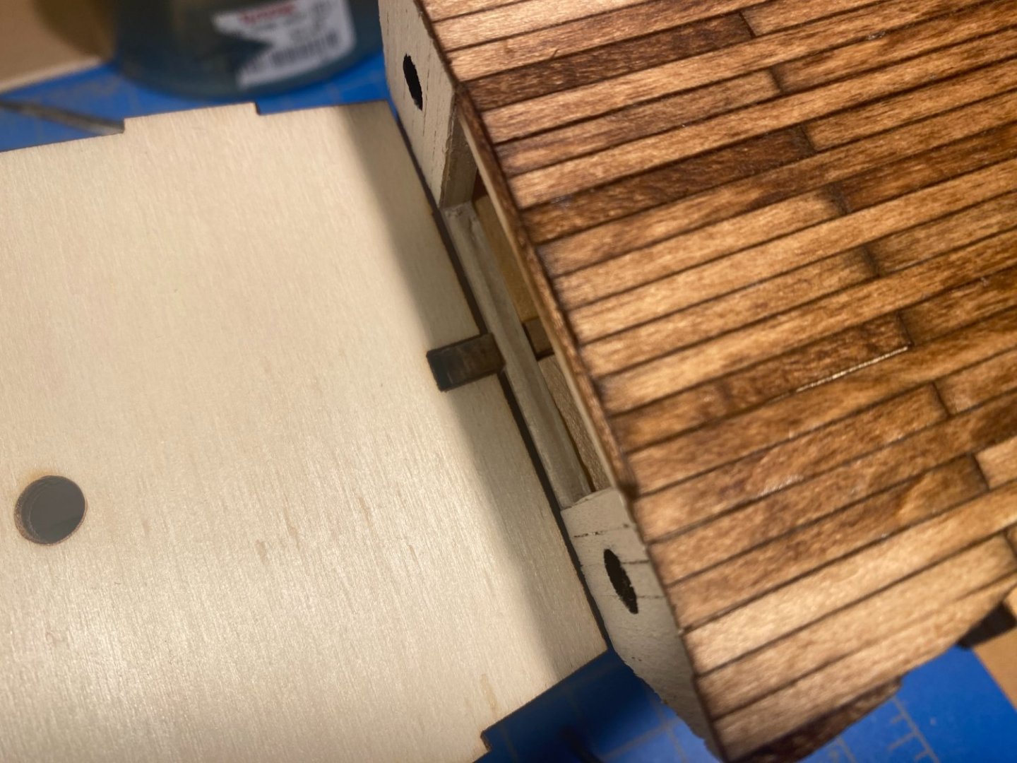
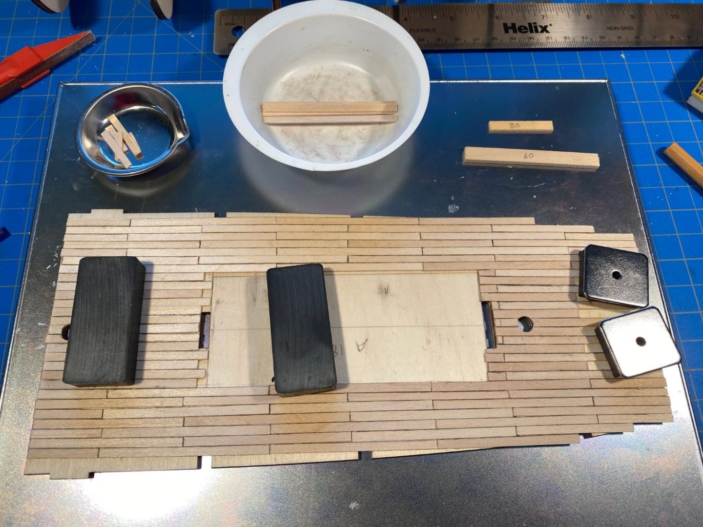
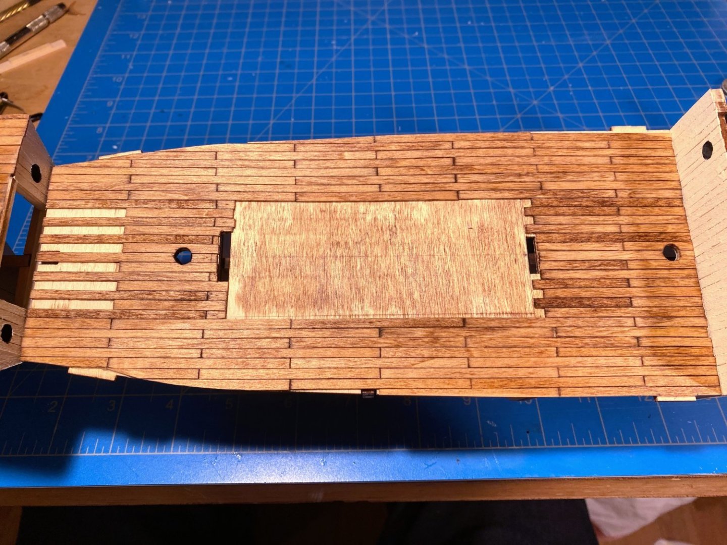
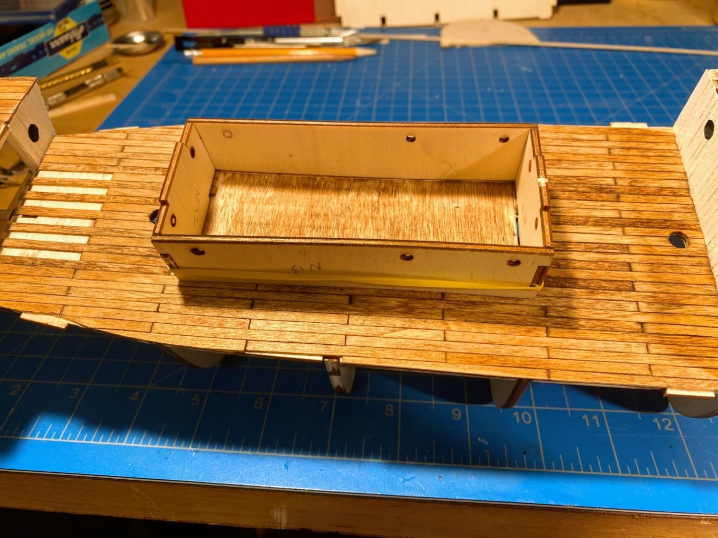
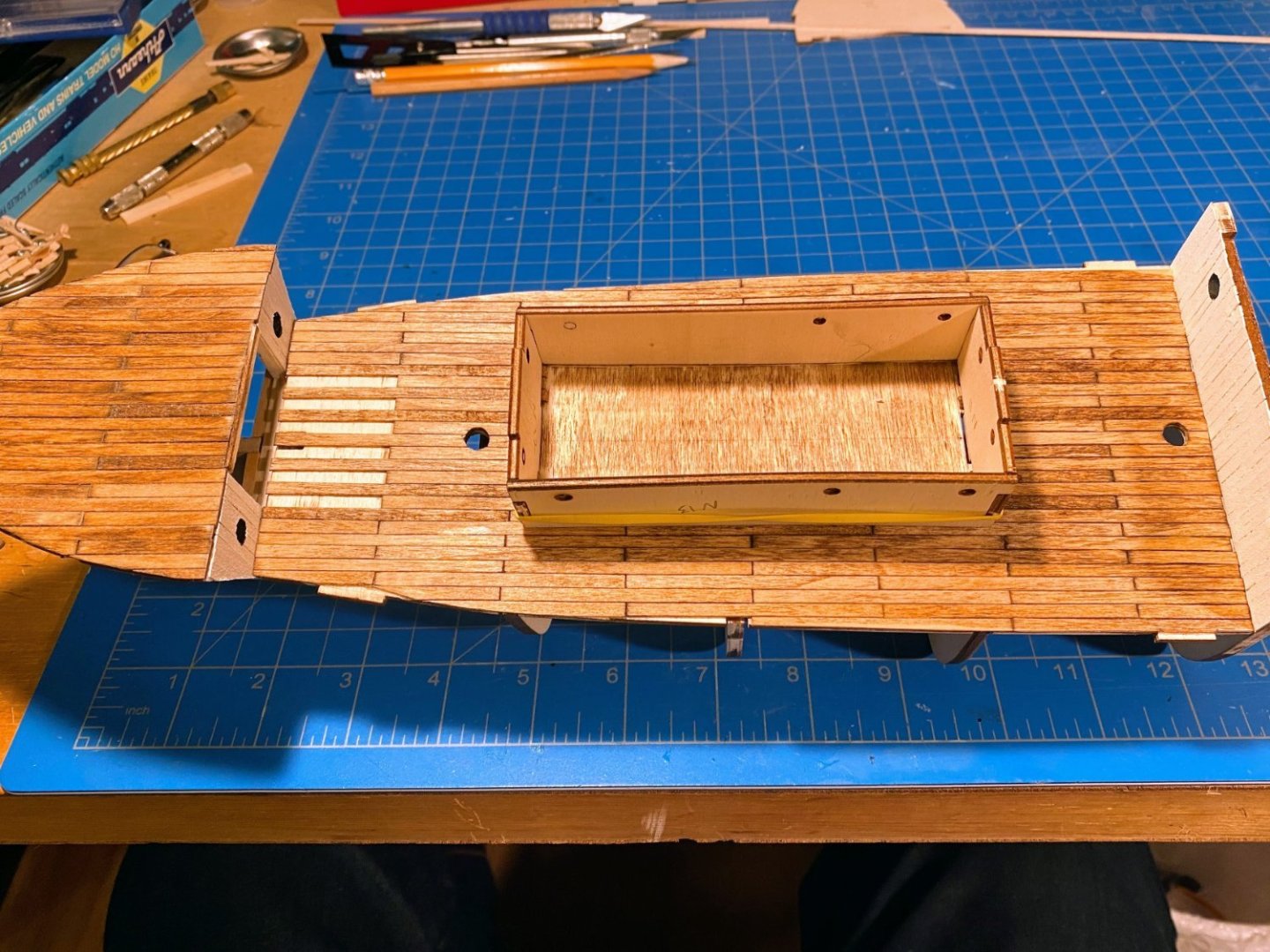
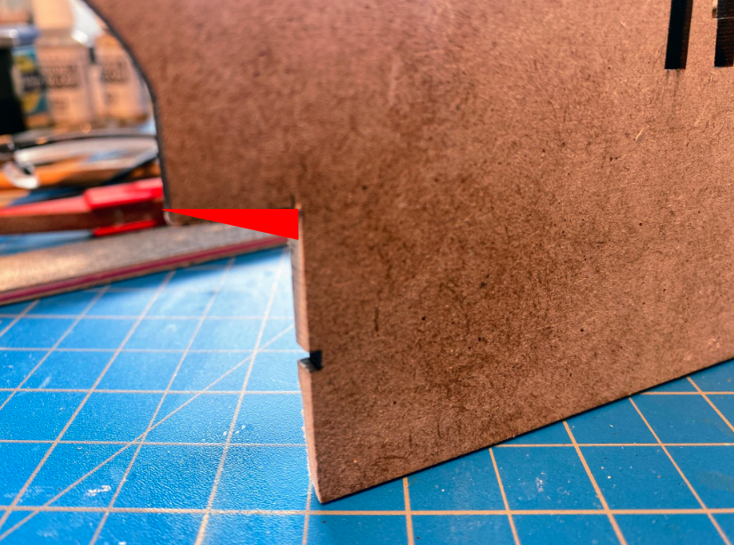
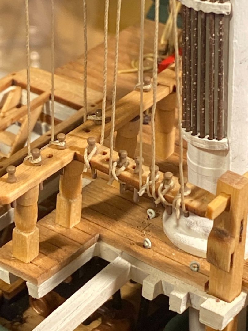
 The foredeck and what I am calling the lower deck are now planked. Some observations: As mentioned previously, the supplied 0.6 x 5mm strips are, to my eye anyway, too wide. I therefore ordered a handful of 1/32 x 1/8 planks to use instead. Assuming my calculations are correct, 5mm translates to about 13¾” wide on the real deck, while 1/8” is a more reasonable 8¾“. I had several stains hanging around, and after a brushing few dabs of each on the backside of the lower deck, I chose one labeled Red Chestnut. I applied Verathane wood conditioner first, brushed it on the foredeck, wiped off the excess, and then let it dry for a few hours. Then I applied a coat of stain. I am not super pleased with the result. It’s darker than I expected, and blotchy. There are plank specific inconsistencies in the appearance, and that’s OK since it highlights the fact that this deck is actually planked with individual planks. But there is a blotchiness that covers multiple planks that I’m not really happy with. Hopefully these issues will become less noticeable with an anchor or two and other deck furniture on deck. I began planking at the aft edge of the subdeck, but then realized as I worked my way out from the center to the edges of the opening below that I should have extended the planks 0.6mm beyond the subdeck, to cover the tops of the planks I previously glued to the bulkhead. Hard to see, but in the photos you can see that I added a 0.6mm strip across the top of the opening to fill the gap. The ends of the deck planks and the face of this strip will be hidden by a strip which will eventually run the width of the ship across the top of the bulkhead. On to the lower deck. Every other plank will extend into the open area under the foredeck, and those planks will be glued in place only when the lower deck is glued in place. Both that deck and the foredeck are only dry fit in these photos. In ordering the narrower planks I made an arithmetic error in calculating how much I would need, and I forgot that the cabin has its own deck to be planked. In the hope that I would have enough wood strips without buying more (a futile hope I later realized), I left unplanked the area under the cabin. In retrospect that was probably not a great idea. Keeping all the planks straight and headed in the same direction, it’s a lot easier to work your way outward from a carefully located center plank. I ended up with some crookedness that fortunately is not very apparent. In the photo below, note the very stupid mistake I made (I think the medical term is “cranial flatulence”) -- while trimming the edge planks to conform to the subdeck, I very carefully cut out one of the slots that hold the top ends of the bulkheads. Those are supposed to be concealed under the planks. Fortunately removing and replacing the damaged planks was not as difficult as I feared. There are two slots in the deck intended to hold tabs on the pieces that make up the fore and aft ends of the cabin, and I cut my planks to leave these slots open. I later discovered that the slots are wider than the tabs that are supposed to fill them. And in the second picture below you can see that with the cabin slid forward to hide that slot, there is an unfortunate gap in planking at the aft slot. I’ve thought of a couple of possible remedies, but haven’t decided yet exactly what to do about that issue. As an aside I mentioned using the under side of this subdeck to test various stains. After the stains dried, I discovered that the subdeck had warped in kind of a wavy way, I guess due to the dabs of liquid. Some years ago I purchased a device designed to help in the assembly of things like cabins -- it’s a steel tray, with magnets to hold pieces in place. Generally it hasn’t proved to be as useful as I expected, but it proved to be very useful here. I turned it upside down and held the subdeck in place on flat bottom with some magnets that came with it, along with a couple of industrial strength magnets I had purchased for some long-forgotten purpose years ago. Planking the subdeck with it forced into an unwarped position reduced the warpage substantially, so that gluing it in place at the appropriate time will be easy. This time I applied the stain more carefully, trying to avoid any accumulation of liquid on the surface. I am much happier with the result, but it's still not quite what I would like it to be. The color isn’t consistent in the photos below, but I think the middle one is probably the most accurate. It's not as red as any of these photos. Finally, there are two holes near the outer edges of this subdeck in line with the hole for the main mast. I planked right over them for now. The instructions show what look like stacks or vents that go in these holes (maybe cookstove stacks?). Looking at the plans shown in my last post, I can’t see that they show up in the side view, but the holes are definitely there in the deck views. Do any of you who have worked on this model or researched Endurance know what they are?
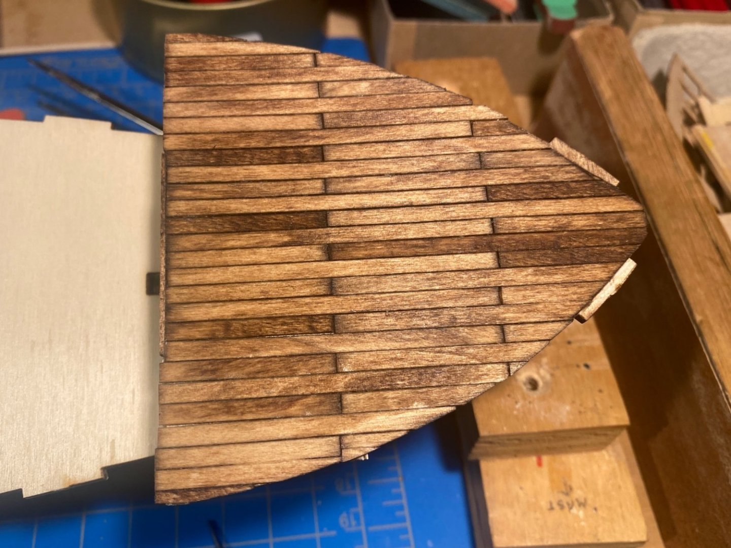


- 206 replies
-
- 5
-

-
- Endurance
- Shackleton
- (and 2 more)
-
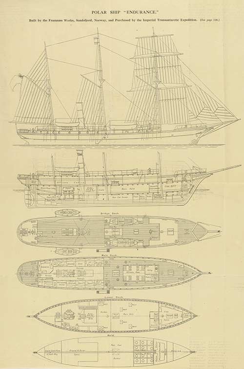
Also referring to Clearway’s blog, there is a discussion between him and Snug Harbor Johnny in which the latter says “The idea for any ship build is to pick a time, place and situation that one wants to represent ... all ships tended to be 'works in progress'.” Certainly good advice. I think my primary reference going forward will be a photo of a sheet of plans I found on the website for the National Library of Scotland, which purport to be plans for the ship Endurance, not the ship as originally built in Norway and given the name Polaris. That would of course be Endurance before it embarked on its journey south and would not include any modifications made along the way or after it got stuck in the ice. To the extent I remain true to Johnny's good advice, these plans will be my reference point. While not entirely clear, these plans would suggest that the lower deck between the foredeck and the cabin simply continues forward under the foredeck, uninterrupted by any bulkhead. There is at least one Frank Hurley photo (I can’t find it now) that shows a partial bulkhead like what B-Ram did on his build and I have pretty much copied on mine.The slope in the propeller insert mentioned in my last post can also be seen in those plans (although ironically those plans could be interpreted as showing the half moon shaped insert as provided in the kit).
- 206 replies
-
- 1
-
-
- Endurance
- Shackleton
- (and 2 more)
-
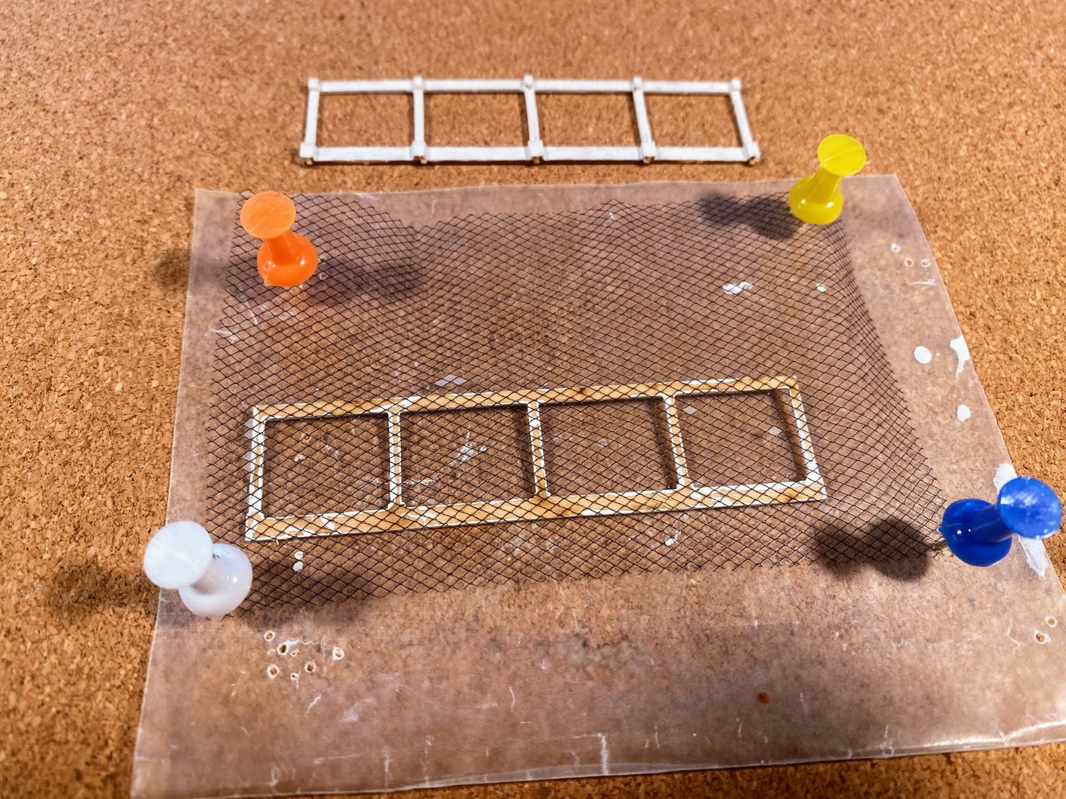
On his build log, Clearway was kind enough to point out that the propeller insert is not exactly a rectangle; rather, the upper part slopes at about 30 degrees. That should be a relatively easy thing to fix. Thanks Clearway.
- 206 replies
-
- 5
-

-
-
- Endurance
- Shackleton
- (and 2 more)
-
Model Shipways. Without them, I would be nowhere near finished with that build.
- 18 replies
-
- 1
-
-
- Constitution
- Model Shipways
- (and 1 more)
-
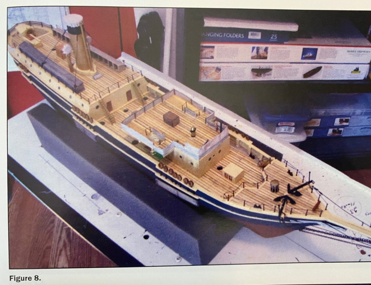
Thanks Keith for pointing out the correct shape of the propeller insert; fortunately it's something I can remedy fairly easily. I have now found a couple of photos of Polaris plans on the National Maritime Museum website. You must have obtained more complete plans, as what I found did not include a deck view. As I mentioned in my build log, Richard Wright wrote an article in the Spring 2016 Nautical Research Journal about his scratch build of Endurance. He mentions having obtained Polaris plans from the Whaling Museum (apparently "Hvalfangstmuseet" in Norwegian) in Sandefjord, Norway, where the ship was built. The photo below shows Mr. Wright's interpretation of the cutout in the anchor deck you refer to, along with other details you may be interested in.
-
Old Navy, delighted to see another Connie cross build log on these boards. As I said on one of my final posts, I found the build to be challenging, rewarding and a lot of fun, notwithstanding some issues you mention, especially with the instructions. I'll follow your build from time to time. Not that am an expert on the subject, but if you have any questions along the way, feel free to ask, either publicly or by private message, as you choose. Enjoy!
-
Clearway, I think I answered my own question. The WC and lamp locker are shown in the photo of plans on the Shackleton family's website http://www.ernestshackleton.net/endurance-expedition
-
Clearway Keith, are you talking about cabins under the foredeck either side of the open area? And which plans do you have? Kieth Black, thanks for posting that NPR link . It was fascinating, and I imagine his book is as well (The Ship Beneath the Ice). Of course there wasn't much that was helpful for building the model. Understandably Mensun wants to talk about his discovery. Has anyone seen the book yet? I'm wondering if it has any photos or videos of the ship in addition to what was released right after the discovery.
-
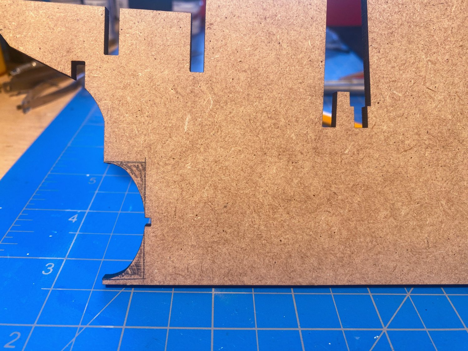
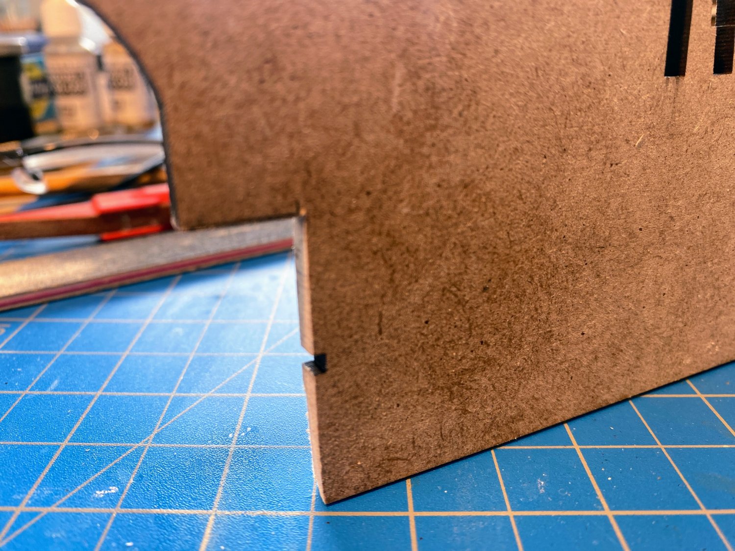
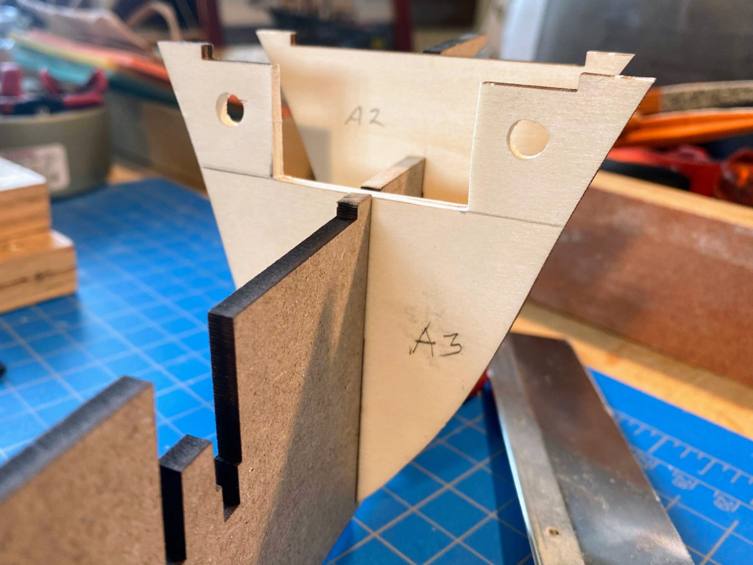
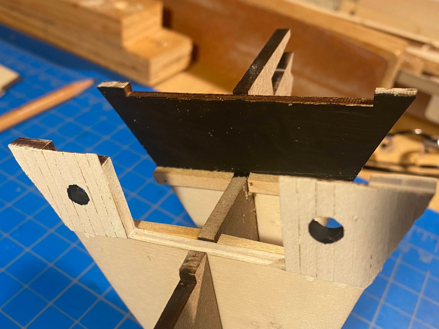
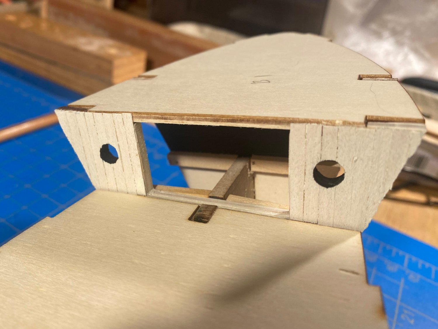
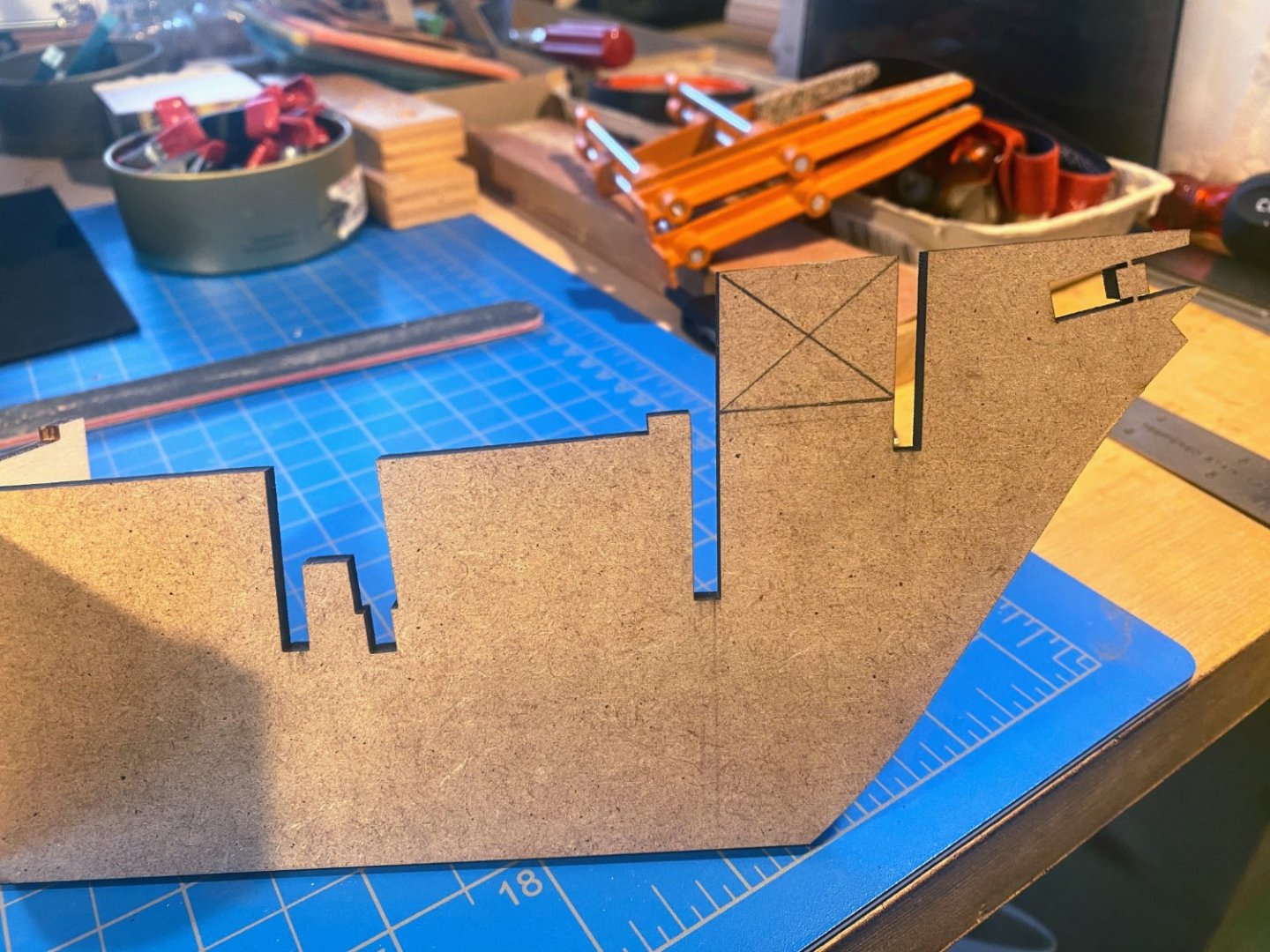
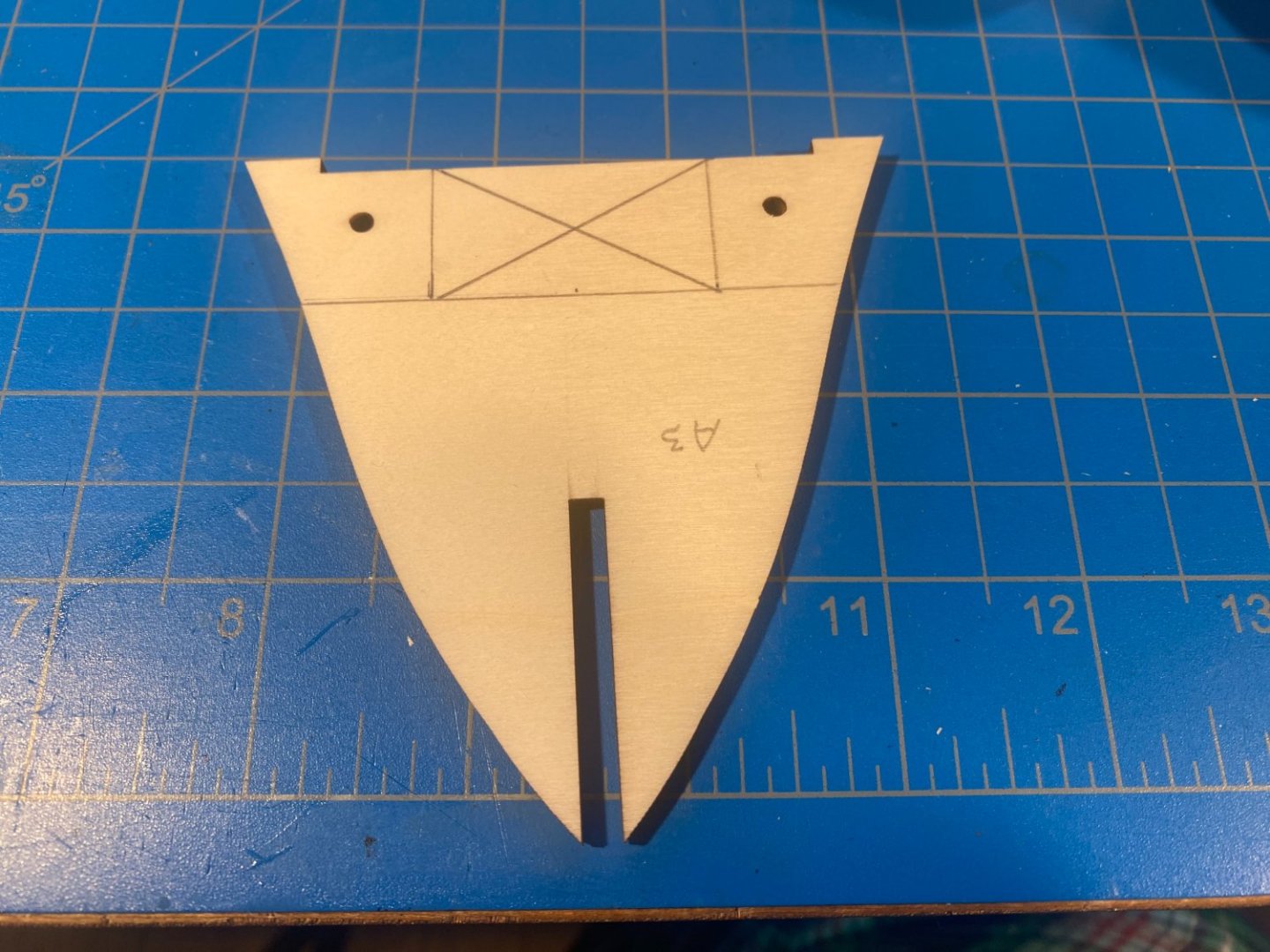
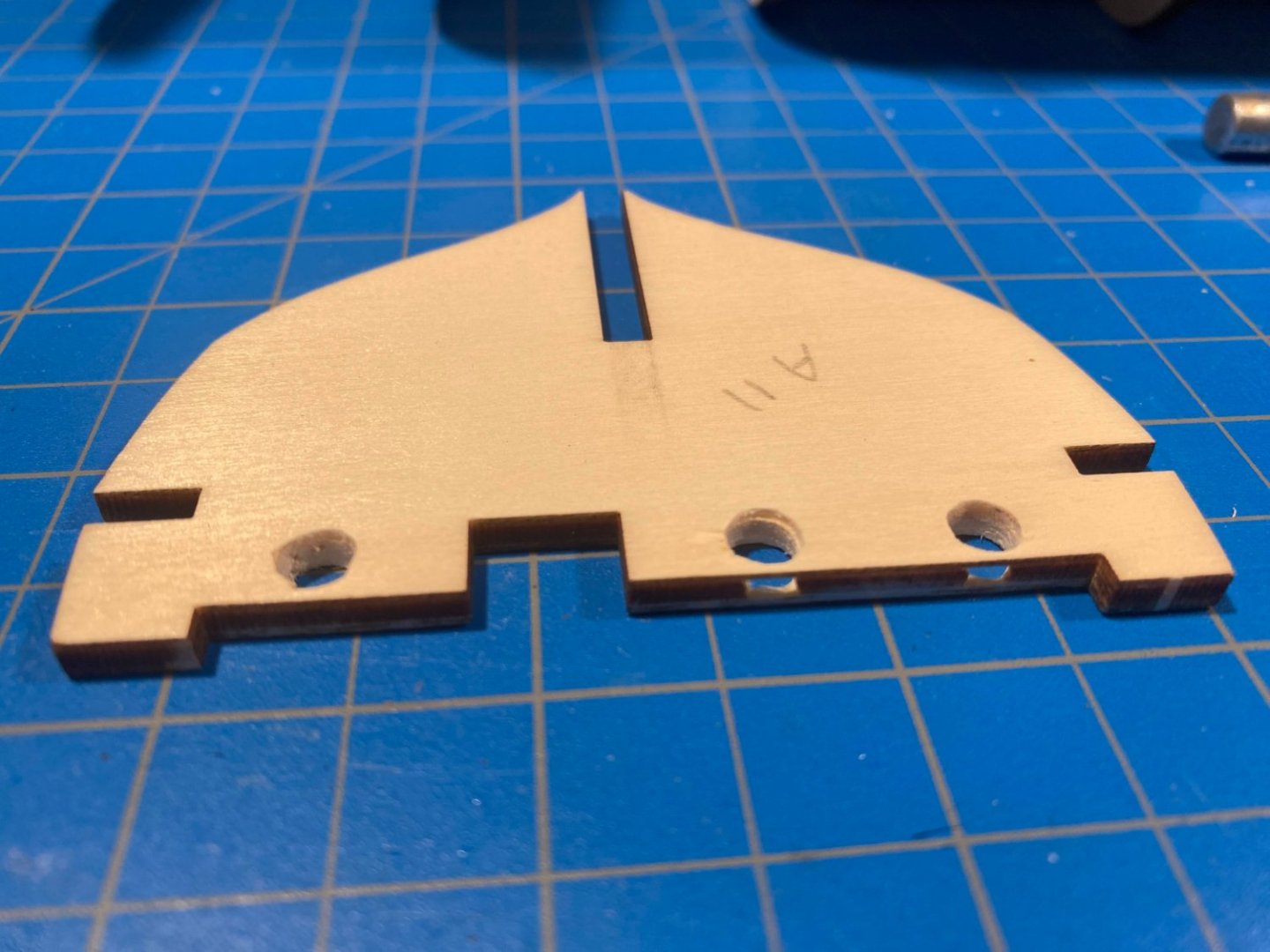
Right off the bat I made two modifications to the MDF false keel. First, I cut out the part that runs between the first and second bulkheads, to accommodate the open area under the forward deck. An opening in the second bulkhead has been included in at least one other build on these boards, and a part of the opening is evident in a few of Frank Hurley’s photos. The second cuts were to make the propeller space rectangular rather than half moon. Again, there are one or two Hurley photos, and old plans, that show a rectangular space for the propeller. I was initially concerned about leaving a narrow piece of false keel along the bottom of this space that would be easily broken off, but then remembered that the keel will be added later in the build, and this small strip can be restored at that time. The opening also required cutting away part of the second bulkhead. As others have noted, the portholes are too small, although they are made to appear larger by brass flanges supplied with the kit. However, most of the portholes on the ship did not have any fixture like this surrounding them, and I decided to not use the flanges. Instead I enlarged the holes from 1/8” to 1/4”, using eight progressively larger bits. I was paranoid that a bit would catch on the soft wood and break, or at least badly damage, the bulkhead. What I found to work quite well was to run my electric drill slowly, and in reverse rather than the usual direction. A few photos of the ship show the bulkheads to be planked on the outside surfaces above the deck. Perhaps the most common alteration made by builders is to use narrower wood strips for planking the deck than those that are supplied in the kit. For this planking I cut supplied wood strips from 5mm to about 3mm, a task I found to be somewhat difficult, since the supplied strips are sycamore and harder to work with than the more typical basswood. I have ordered some 1/32 x 1/8 basswood strips for the deck planking. I painted the bulkhead planking white. I used a Model Shipways paint labeled “Warm White”. It is slightly off white and not as bright as straight white, which I find more appropriate for a work boat. I painted the insides of the portholes black to give them some depth. I also painted black the visible part of the area under the foredeck, and installed some wood strips to support decking in there. The subdecks shown in the photos below are only dry fit in place for now. In the next to last bulkhead, which faces aft, the existing holes are too close to the top edge to enlarge them to 1/4”. In the photo below you can see that the middle section of the plywood came out next to the right two portholes. I stopped drilling when the holes had reached 7/32”. That bulkhead needs to be planked, and then I move on to planking the decks.


- 206 replies
-
- 6
-
-
- Endurance
- Shackleton
- (and 2 more)
-
Generally I have to say I prefer building to research, and I have not done much of the latter as part of my previous builds. But Endurance will be a little different. The ship was built in Norway, under the name Polaris, completed in late 1912. Ernest Shackleton bought it before it ever set sail, and with remarkable prescience, he renamed it Endurance. The ship sailed from England on his ill-fated journey in August 1914. Endurance became trapped in the ice 5 months later, it was eventually crushed and destroyed, and the rest is well-known history. Shackleton and a few members of the crew reached civilization after a harrowing journey in one of the ship’s small boats, and he returned with another ship to rescue the rest of the crew, all of whom survived two winters in Antarctica. Determining what any historical ship looked like can be challenging, in part because most of them changed over time. In the case of Endurance, much has been written and even photographed about the remarkable human achievement. But that story is so gripping and compelling that it seems that the ship itself has been neglected. I have not been able to determine what changes Shackleton made to the ship after he purchased it. Endurance's voyage began only a handful of days after World War I broke out, and obviously the world's attention was not focused elsewhere. Frank Hurley, the well-known early 20th century photographer, did not join the voyage until the ship left Buenos Aires in October 2014. Just under a year ago the remains of the ship were found on the ocean floor, and a book has just been released (which I haven’t seen yet) about the search and the discovery. Hopefully we will be learning more about the ship soon. What little I have learned about Endurance came from the following: Alfred Lansing, Endurance, originally written in 1959 and reissued more than once since then. I read this book several years ago, and seem to have lost it sometime since then. Caroline Alexander, The Endurance: Shackleton’s Legendary Antarctic Expedition, 1998 South with Endurance, the Photographs of Frank Hurley, 2001, the most extensive collection of photographs taken by Mr. Hurley Richard Wright’s article in the Spring 2016 edition of Nautical Research Journal, Building Shackleton’s Endurance, describing his pre-Occre, scratch build of the ship Numerous Hurley photographs various places on the web, mostly part of the Getty Images site Website of the Shackleton Museum, located in Athy, Ireland. Two things stand out here: a very large scale model of the ship, which can be viewed from many angles, and a video from a submersible, showing the discovery of the ship last year Website of the National Library of Scotland, which includes a photograph of a sheet of plans for the ship (search “Endurance Diagram”) http://www.ernestshackleton.net, which includes photographs, including one of a plan sheet said to be “from the family collection” The Alamy photography website with photos, including an interesting cutaway drawing found by searching for “cutaway view of Endurance” And last but certainly not least, the several build logs on these boards, and the contributions of many who have followed them. To the best of my knowledge, the only FINISHED one is the excellent log posted by HakeZou I thought I would also post my first build photos this morning, but life seems to be getting in the way. Hopefully later today.
- 206 replies
-
- 2
-
-
- Endurance
- Shackleton
- (and 2 more)
-
Johnny and Keith, I am delighted that you came across my post. I have followed your build since the beginning Keith, and your research and knowledge of the ship Johnny is a great addition. The ongoing dialog between the two of you has been really helpful to me. Thoughts and comments about my build, once it's truly underway, will be more than welcome. Another post coming along shortly.
- 206 replies
-
- 2
-
-
- Endurance
- Shackleton
- (and 2 more)
-
Somewhat presumptuously, given the many Endurance build logs already on these boards, I have decided to add yet another one. This post will explain why. Within the next day or two I will add posts listing the research sources I have come across, and photos of some kit-bashing I am doing at the very beginning of the build. It seems to me that ship models can be placed on a continuum, with beautiful models at one end, and historically accurate, or at least realistic, ones at the other end. Built as instructed, OcCre models are toward the former end -- exposed brass, different kinds of unfinished wood, etc. My first model, 30+ years ago, was Artesania Latina’s Bluenose. Nothing on it is painted, and it has a variety of beautiful woods, and brass anchor chains. I’m proud of the work I did, and I admire the beautiful models of this style others have displayed on this great website. But since that first model, I have gravitated more toward the other end of the continuum, trying to build models that are at least credible reproductions of the real thing. Not better than the ones just described; just a different style. Doing so with this OcCre build will require some kit-bashing, and that is what I hope to devote most of this build log to. I also hope to be advised, informed and inspired by the comments of those who choose to follow me on this journey. And with a little luck, maybe I can return the favor.
- 206 replies
-
- 6
-
-
- Endurance
- Shackleton
- (and 2 more)
-
Thank you Bob, Jonathan, Brian and Tim for your kind words, and thank you to the rest of you for the thumbs up. This would have been a much less satisfying build without the encouragement and advice I received from so many people on these boards. And yes, Jonathan, I intend to get a case. But I probably should acknowledge that I've been intending to get a case for my Niagara, and that build was completed about 20 years ago. I'm going to have to work harder on getting around to it. The good news is the Niagara has survived without a case remarkably well.
- 163 replies
-
- 2
-
-
- Model Shipways
- Constitution
- (and 2 more)
-
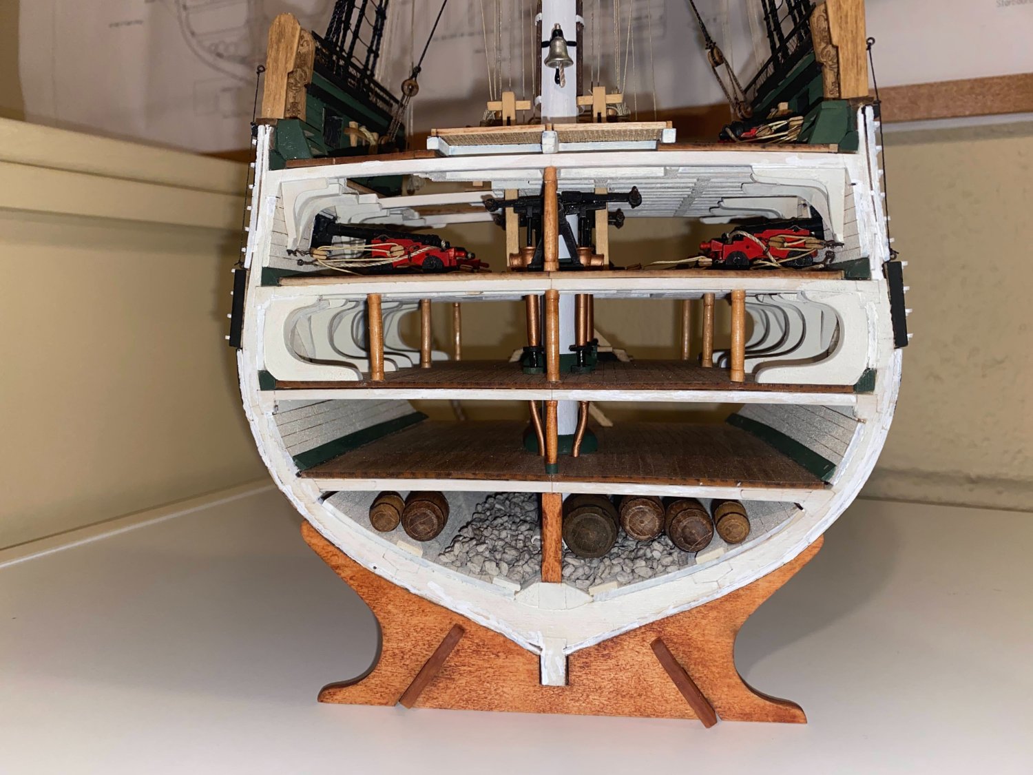
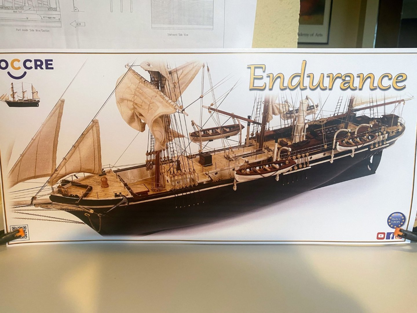
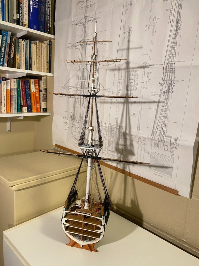
This has been a challenging--and very fun and rewarding--build, and I’m excited to say it’s FINISHED!! The Model Shipways kit is outstanding--great detail, fittings, materials, laser-cut parts and plans. As I mentioned a few times, the instructions sometimes left a few things to be desired, but on the whole they were pretty good, and certainly comprehensive. I would recommend the kit enthusiastically to any builder with a little bit of experience under his/her belt. And now for some photos (perhaps too many photos), followed by a few comments on my next build. Coming up next is Occre’s model of Ernest Shackleton’s Endurance. This will be my first experience with Occre, and I’m looking forward to it. There are quite a few Endurance build logs on these boards, which makes me think twice before writing yet another one. I will probably post one anyway, but perhaps posting less frequently, and primarily when I am deviating from the kit or when something out of the ordinary deserves comment. I don’t anticipate getting started for a month or two, first simply taking a break, then some time reviewing the instructions, taking inventory, reviewing the existing logs, doing some internet research, and doing enough construction to have something to talk about. I look forward to the journey.


- 163 replies
-
- 5
-

-
-
- Model Shipways
- Constitution
- (and 2 more)
-
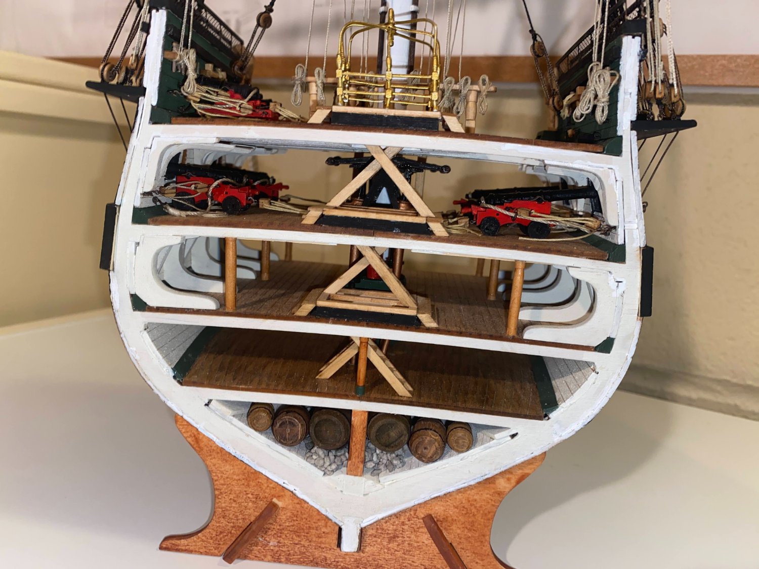
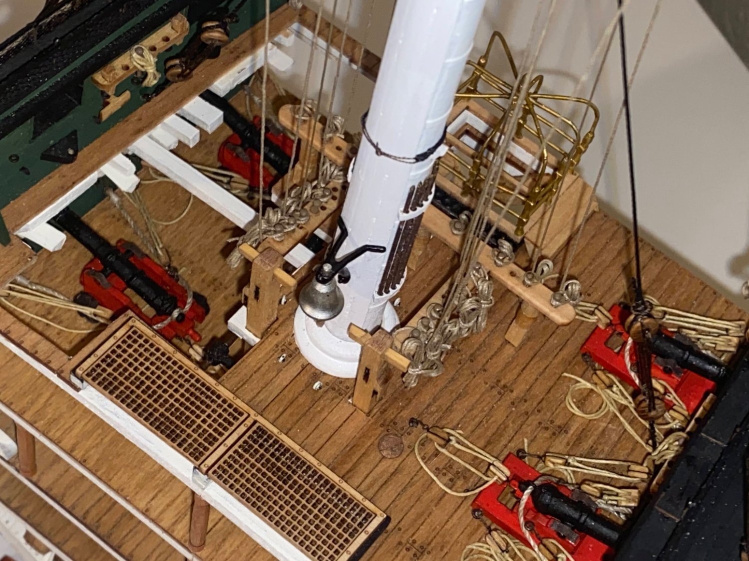
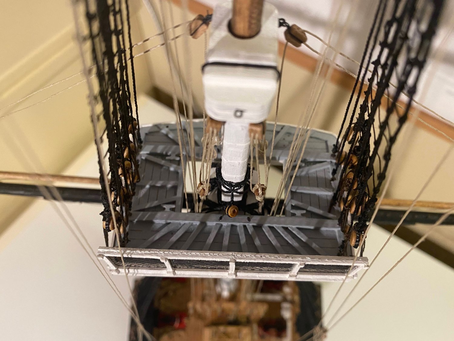
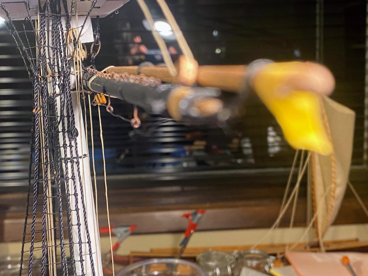
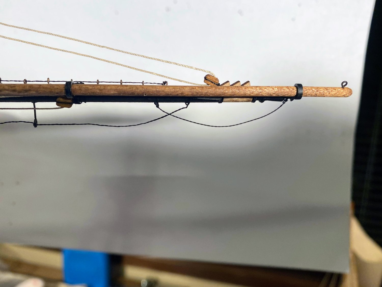
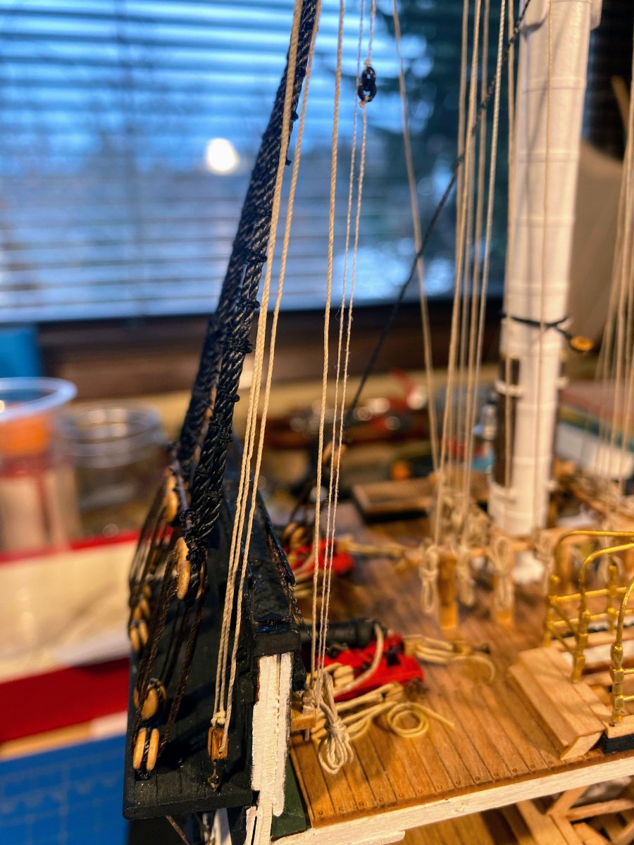
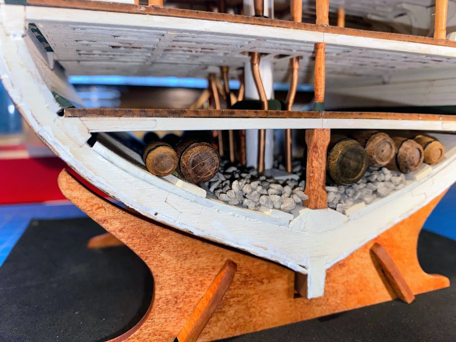
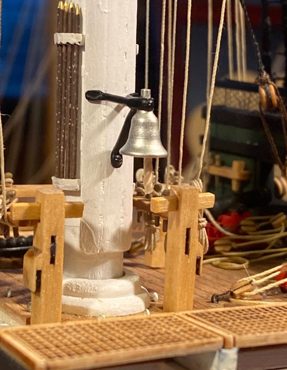
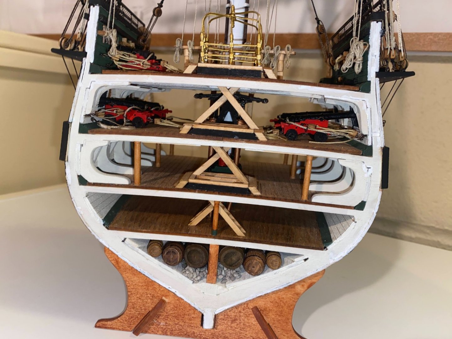
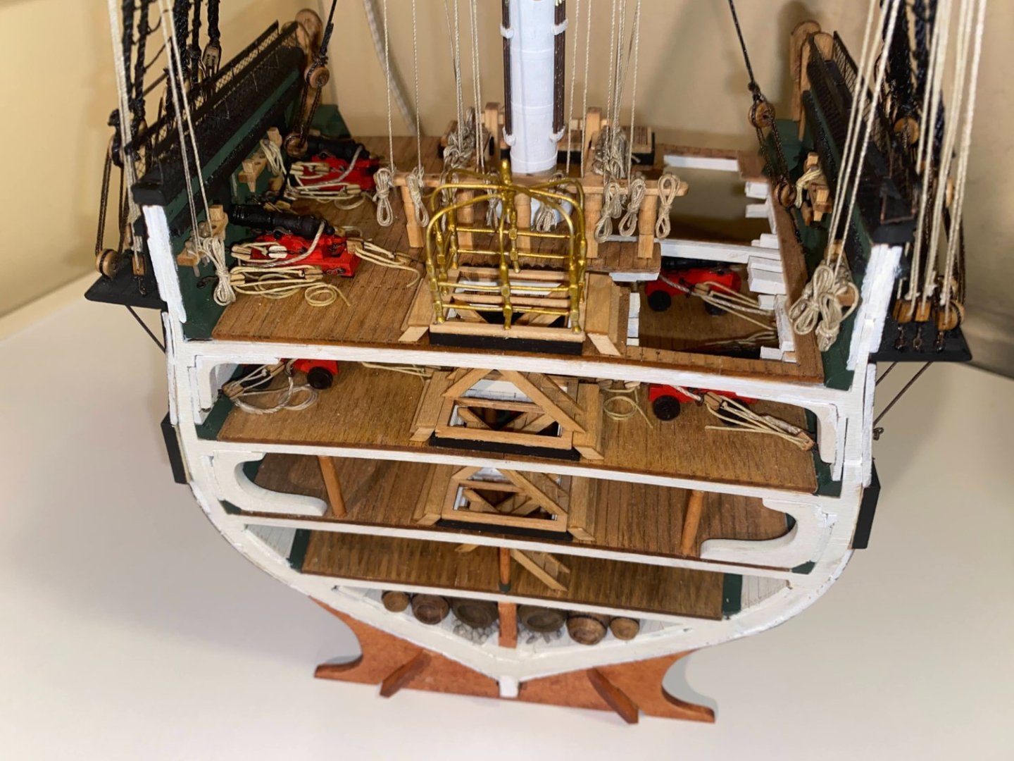
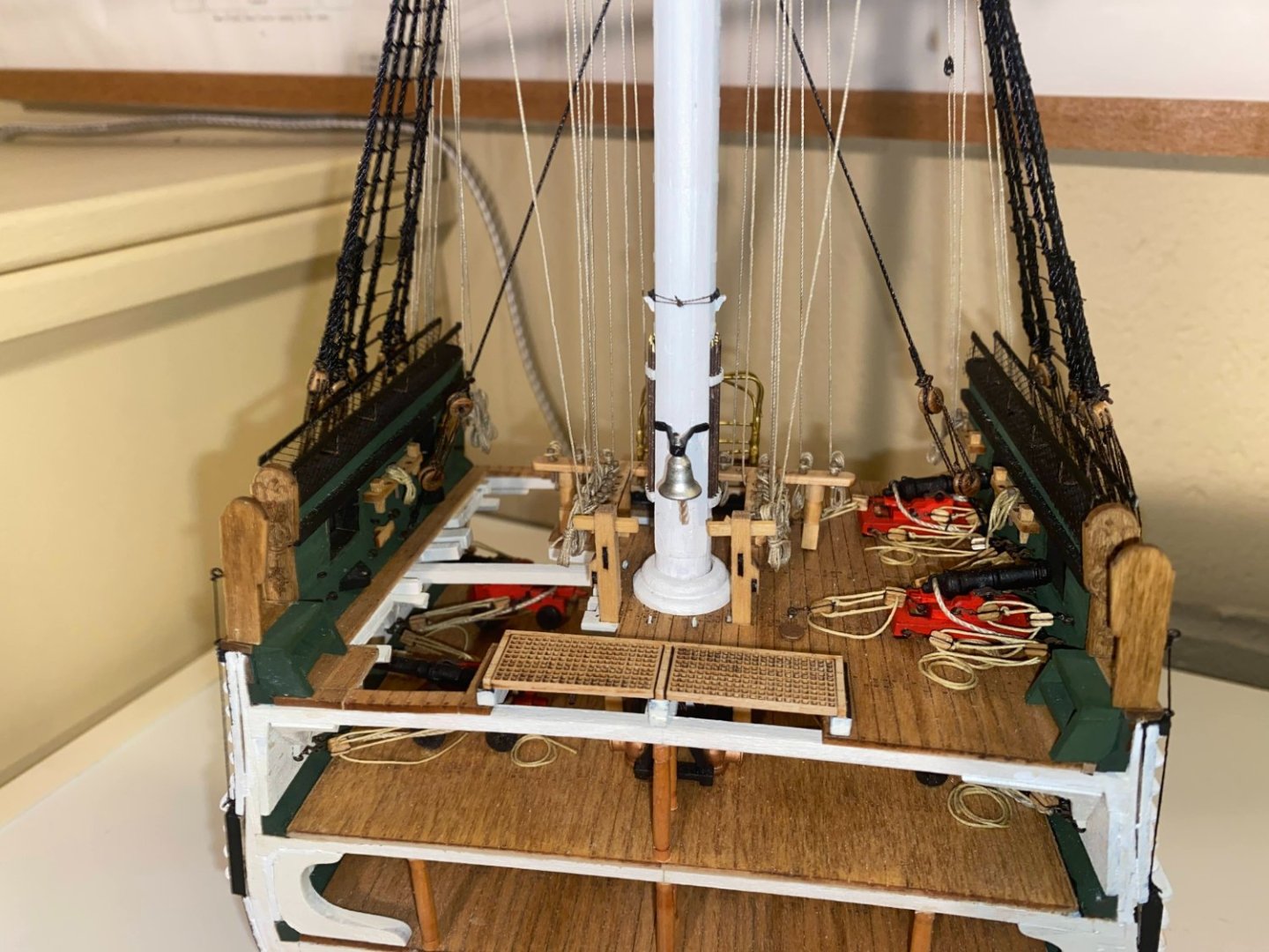
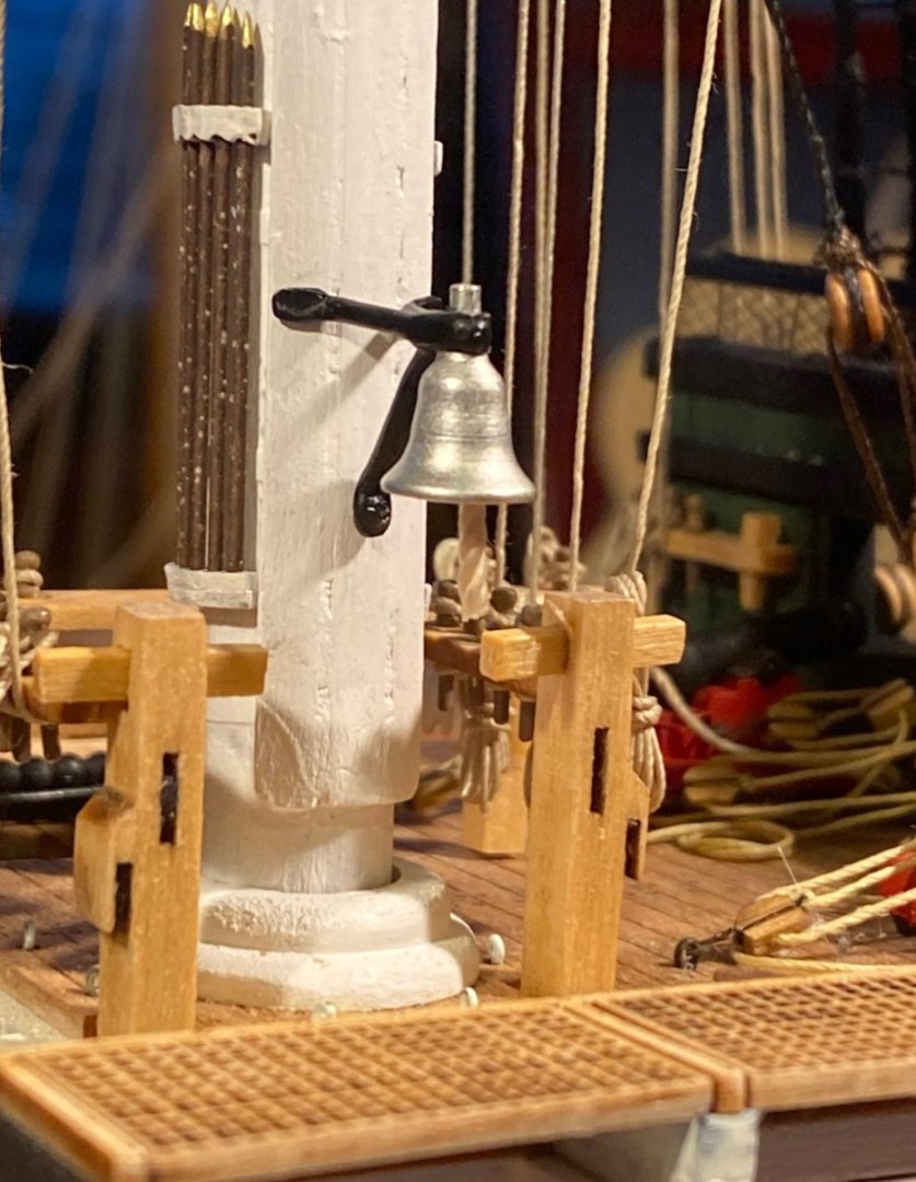
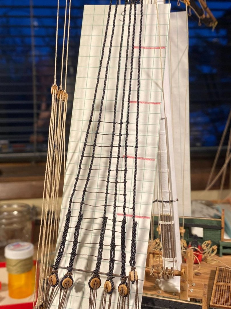
The end-of-the-build to do list . . . I finished the lower shroud ratlines. Back when those shrouds were installed I made the decision to defer these ratlines until the running rigging was finished, for fear that the former would get in the way of rigging the latter. That was a mistake. The running rigging made rigging the ratlines more challenging, and I didn’t even think about the lower yard getting in the way of rigging the last several ratlines at the upper end. I found myself wanting to put my face where the end of the studding sail boom was, and to avoid damaging the boom (or my eyes), I put a yellow warning flag made of masking tape at the end of each boom. The forward companionway heading boards are precariously glued to the ship standing on one of their 1\16” edges. To give them a little more security, I glued a short length of narrow gauge wire in a small hole in each piece to act as a reinforcing pin glued into a corresponding hole in the companionway. Unfortunately I didn’t get a picture of the pin, but you should get the idea. The plans show an extension of the footrope (a Flemish horse) at the ends of the lower and topsail yards, with the notation “Optional detail depending upon the period being built.” One of my earlier posts asked if anyone knew what “period” was being referred to, and I got no responses. I simply decided that my model needed this additional detail. The kit comes with a long, thin pendant, and the instructions provide a detailed description of how to make the flag look like it’s blowing in the wind. I decided I just didn’t like the look of the pendant and didn’t even try to include it, but I did string a halyard through a small block at the top of the mast down to the outer belaying pin on the aft port bulwark. I linked a couple of small rings together to roughly simulate clips or shackles that would attach to two corners of any flag. Then I took a couple of wraps around the belaying pin with the lower end of the rope loop. There would be no rope coil here, as the halyard is a loop. Over a period of weeks or months after I glued barrels into the gravel in the bilge, a number of them came loose and fell out, both fore and aft. On the aft end, I glued all the missing barrels back in, filling the gaps in Connie’s toothy grin. At the forward end, I left two barrels out, in order to allow a view of the bottom of the mast and the ends of the bilge pump pipes buried in the gravel. Finally I installed the previously constructed bell on the front of the mast. My FINISHED post, after taking some FINISHED photos, will come along within a few days, maybe sooner.


- 163 replies
-
- 6
-
-
-
- Model Shipways
- Constitution
- (and 2 more)
-
Thanks Brian. Cleaning up and bending to shape may not be my favorite activity, but I have a lot more confidence doing that than scratch building parts like that. Kudos to you for making your own parts. I don't think FINISHED will be bitter sweet for me; I'm already getting excited for my next build.
- 163 replies
-
- 1
-
-
- Model Shipways
- Constitution
- (and 2 more)
-
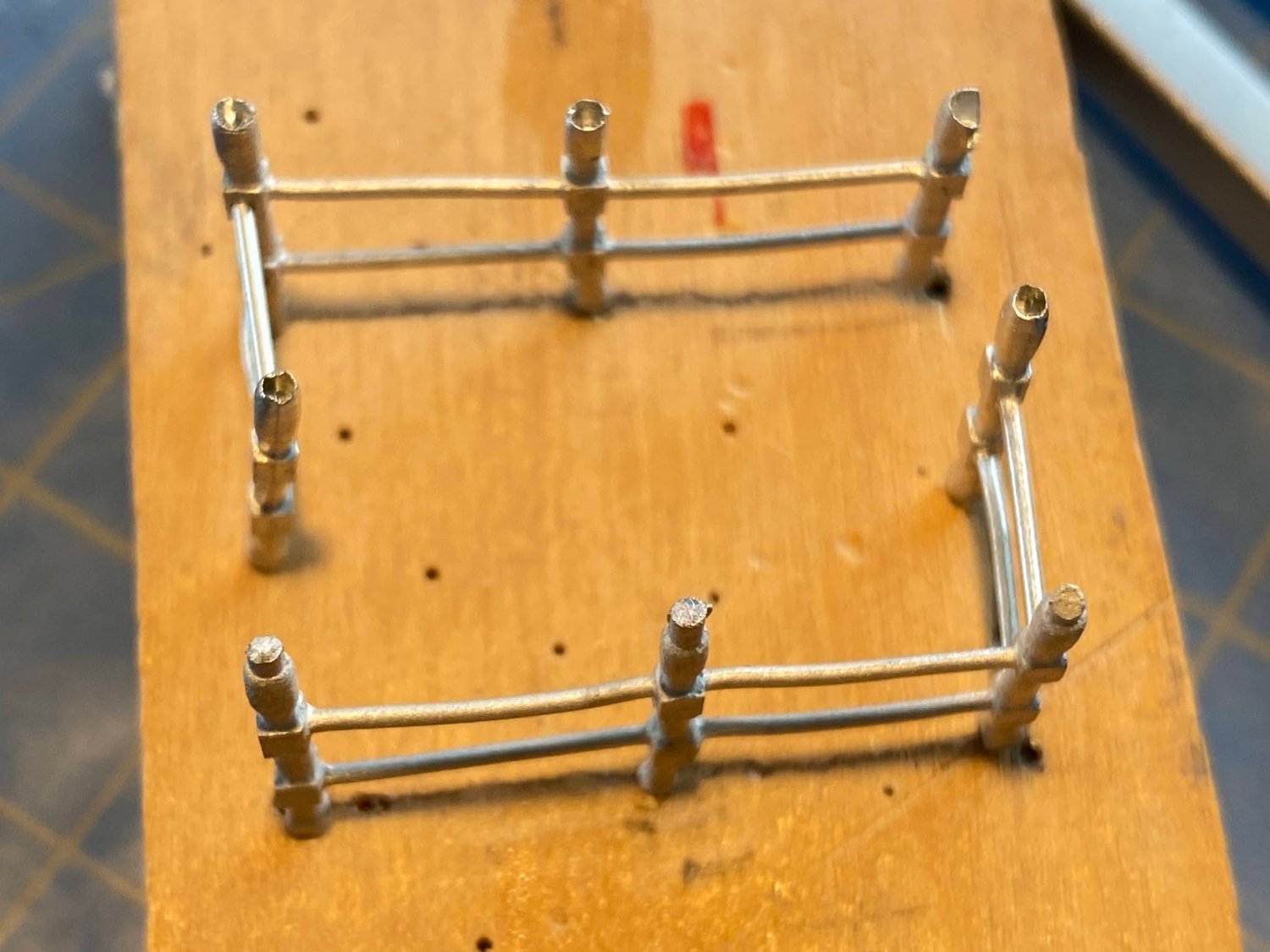
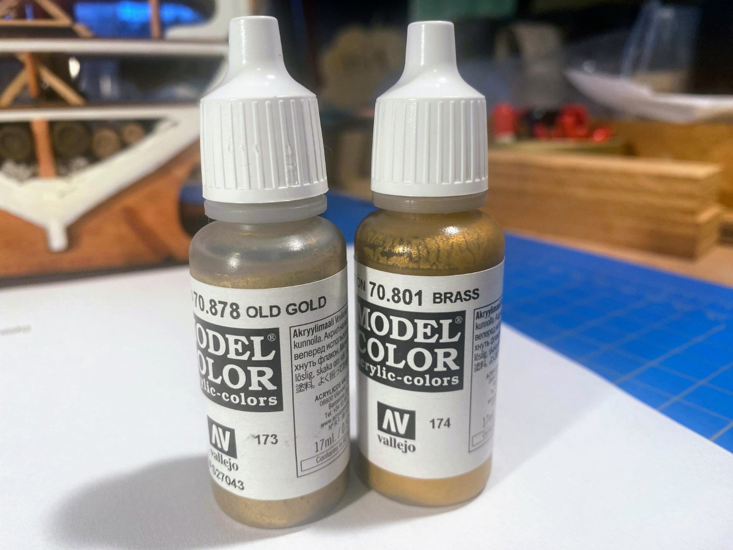
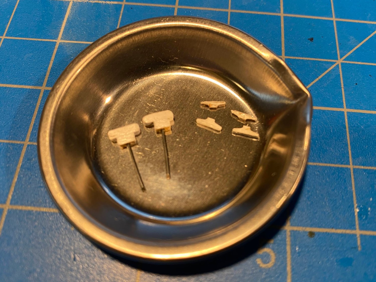
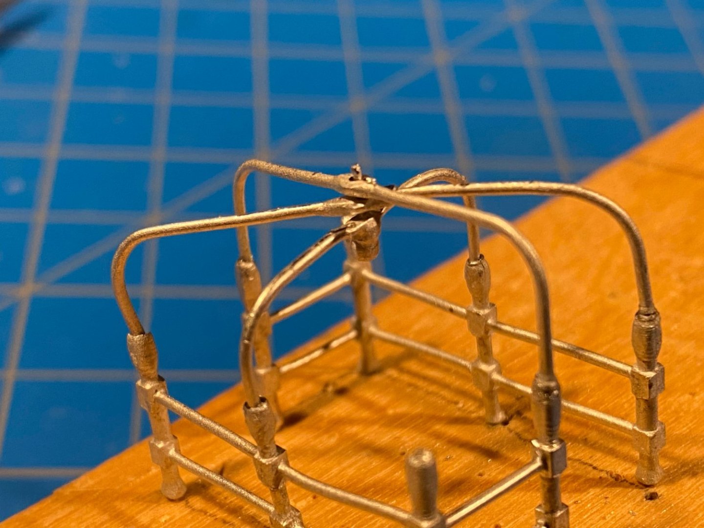
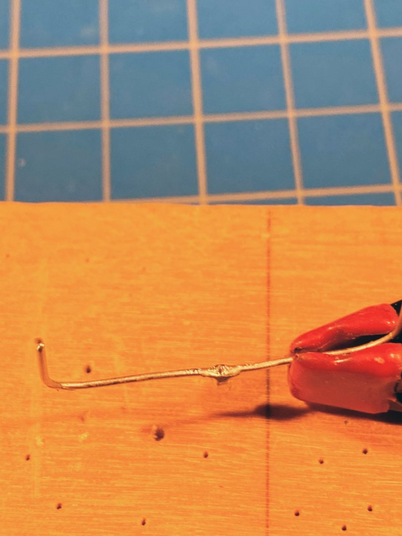
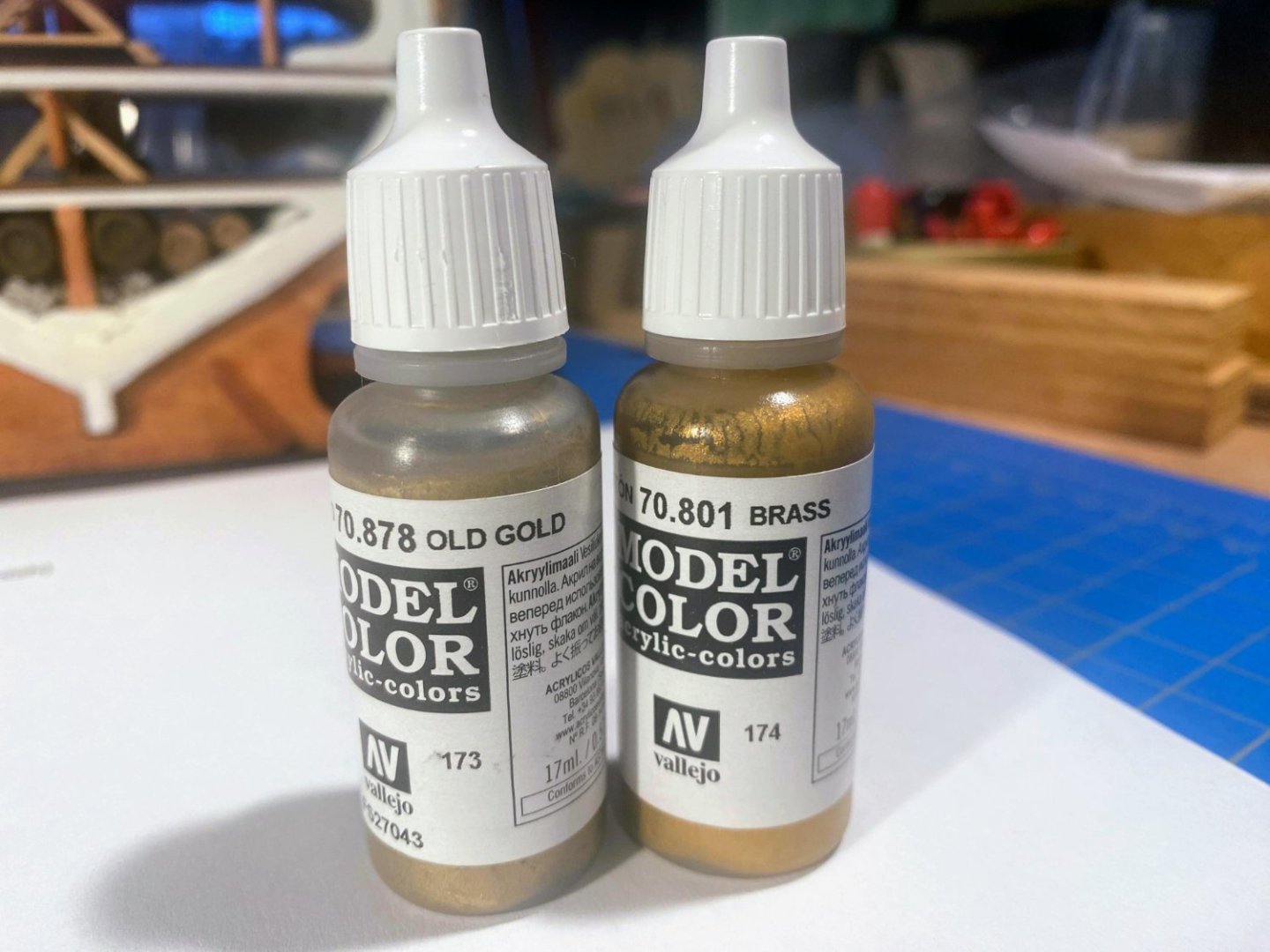
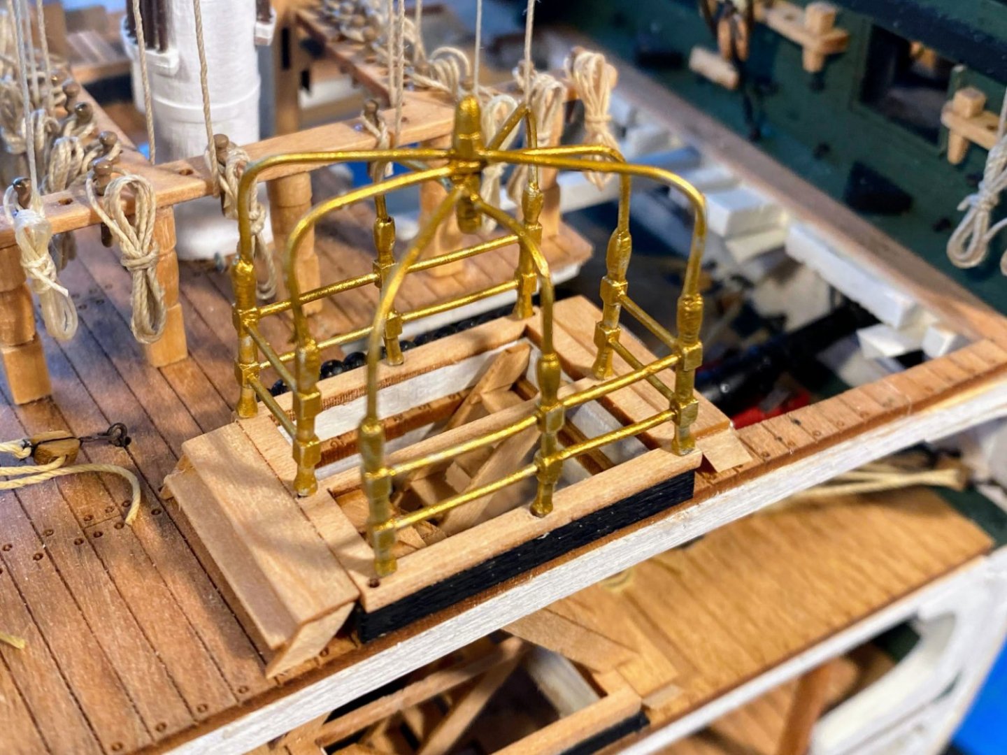
Getting awfully close to adding “FINISHED” to the name of this log . . . I’m excited. This post’s project is what the instructions call the “hatchway canopy frame”. In my mind it became the Gilded Birdcage. The Birdcage is built from eight Britannia metal pieces. Typical to these kinds of fittings, there was a lot of flashing to be trimmed off, and they all were bent out of shape to one degree or another. None of which was a problem. There were however some challenges. As can be seen in the picture immediately below, the bottom half of the Birdcage consists of two pairs of fence-like pieces. The other four pieces are arc-like frames which make up the upper half and top of the Birdcage. The bottoms of these upper pieces fit into shallow holes in the tops of the lower piece fence posts. Of each pair of fence pieces, one came with this hole nicely formed, and one came with an extension that needed to be cut off and no formed hole. In the picture below, I have cut off the extension and drilled the hole in one of the four fence posts, but not yet in the other three. Needless to say, drilling the holes in these tiny pieces was a challenge, to say the least. The instructions direct building the Birdcage in the hatchway frame on the model, then removing it for painting before finally gluing it in place. However, the pieces needed a lot of precise bending to get them to fit right, and there was no way my fat thumbs and fingers would have adequate space to do that if the assembly was on the model. So I carefully duplicated in a spare piece of wood the holes that were pre-drilled in the hatchway frame and built the Birdcage off the model. As mentioned before, there are four upper pieces. The lower one of these has a pin which fits through holes in the middle of the pieces above it, as can be seen in the next picture below. The upper piece has a decorative knob on top, with a small hole inside it to take the upper end of the pin from the lower piece. That hole had to be drilled as it was not drilled in the upper piece as supplied. The hole after I drilled it can be sort of seen in the second picture below, which is unfortunately not well focused. The Birdcage on the real ship appears to be unfinished brass. I bought a couple of bottles of Vallejo paint (a brand I haven’t used before), color-labeled Brass and Old Gold. In the bottle Brass looked like what I wanted, and that is what I painted the Birdcage with. It fits tightly in most of the holes in the hatchway frame (two of the holes were simply out of line), and I did not feel a need to glue it in place. Painted and installed on the model, it’s a bit bright for my taste (thus the Gilded Birdcage), and I thought about pulling it off and repainting it with Old Gold. But I fear that may result in something that looks more like Drab Mud, so I think I will leave it as is. 😊 I now have a list of about a dozen things that need attention before I can truly call this build finished. Those will be the subject of my next post.

- 163 replies
-
- 6
-
-
-
- Model Shipways
- Constitution
- (and 2 more)
-
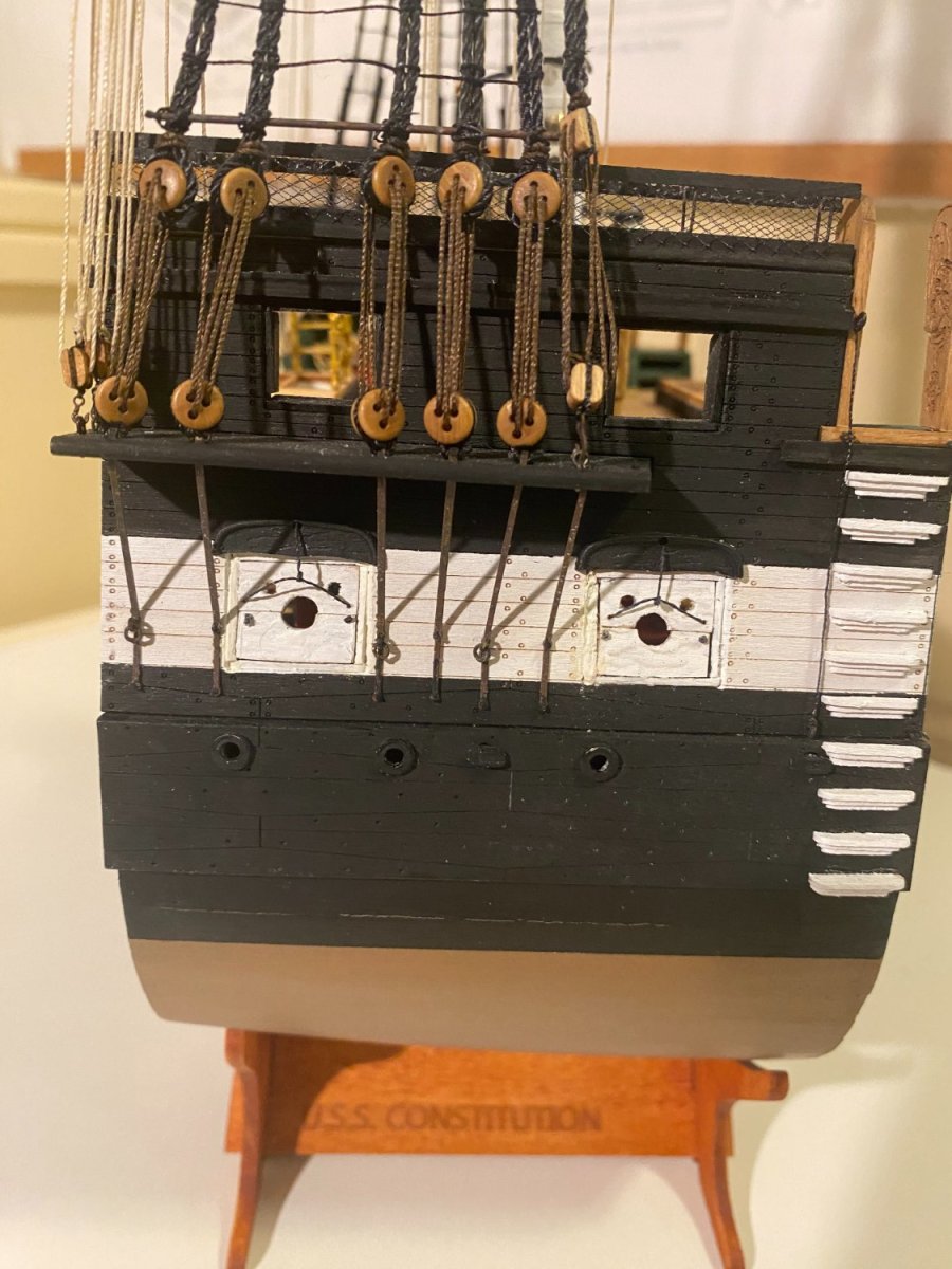
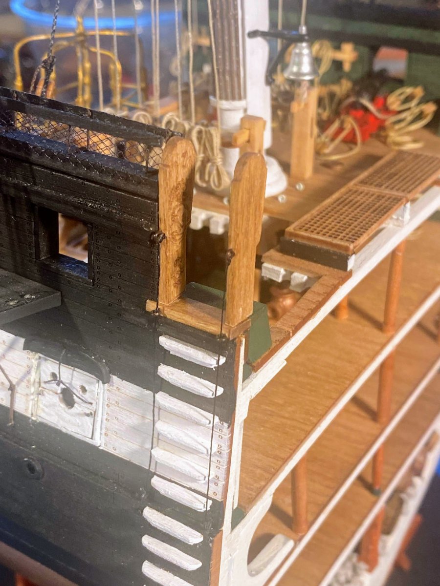
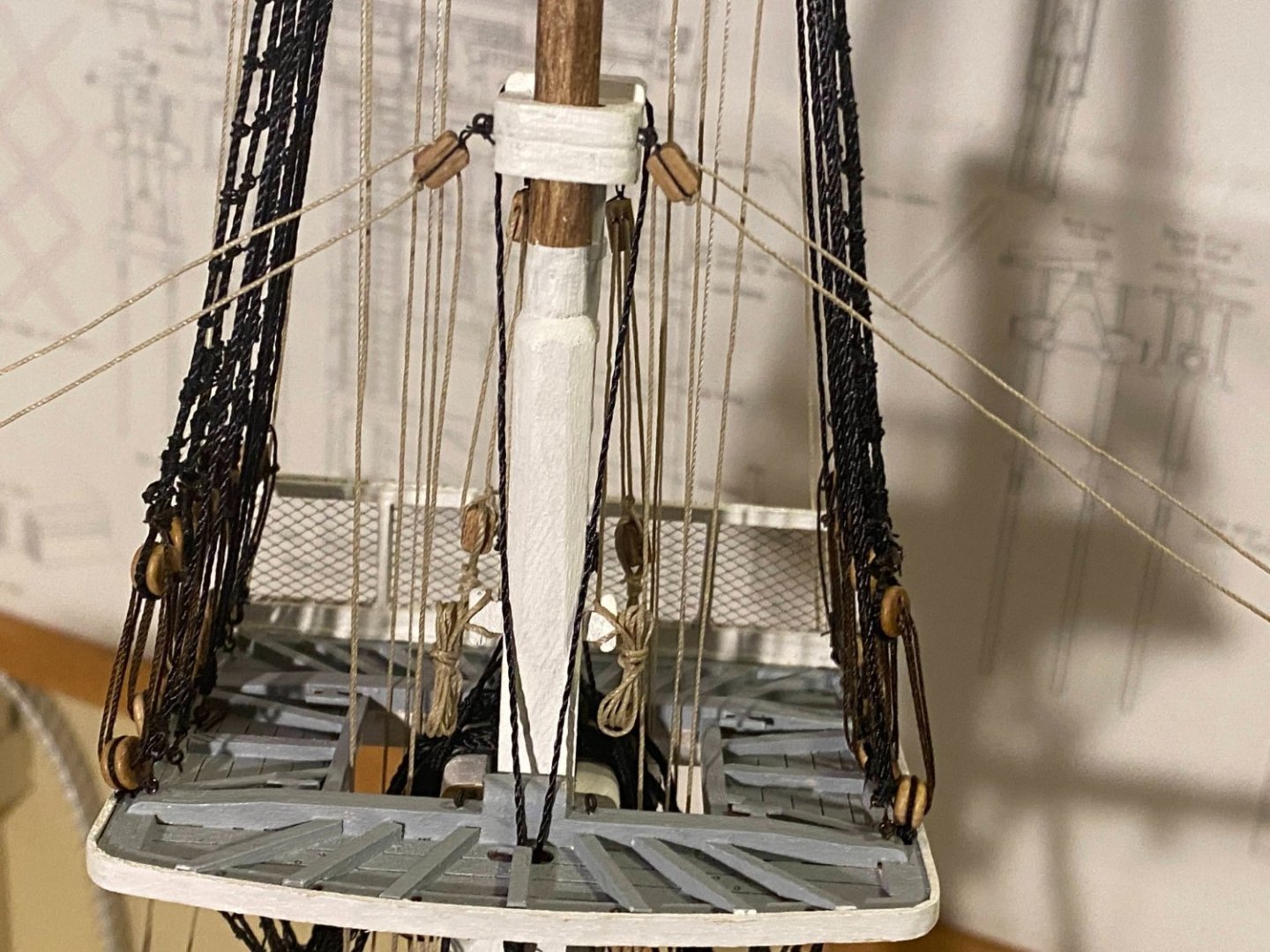
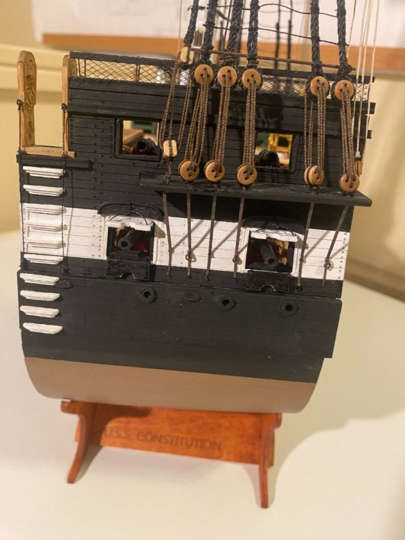
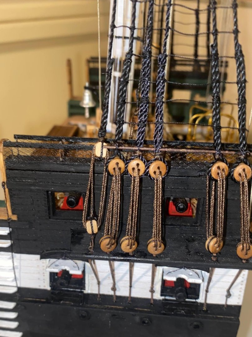
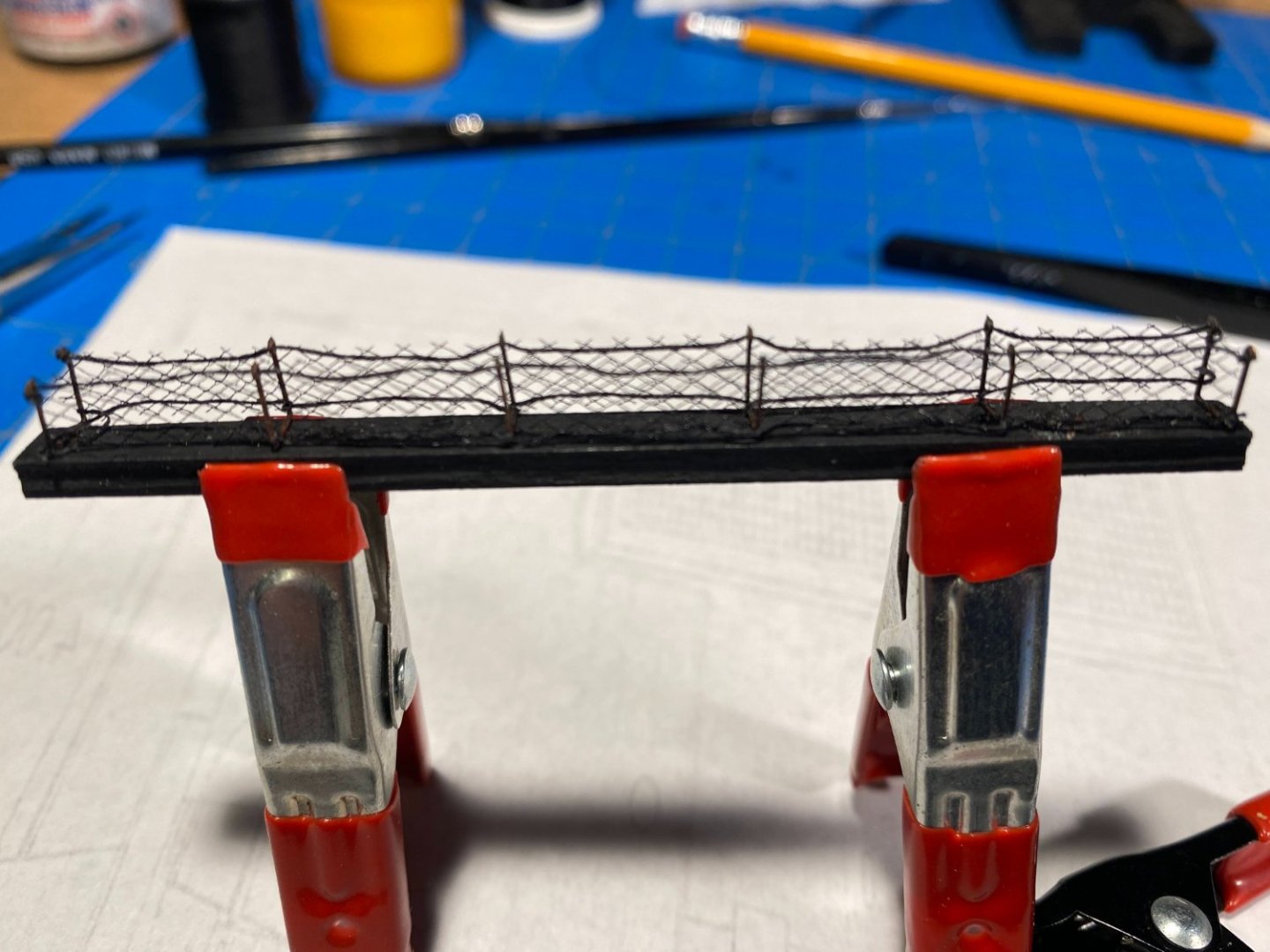
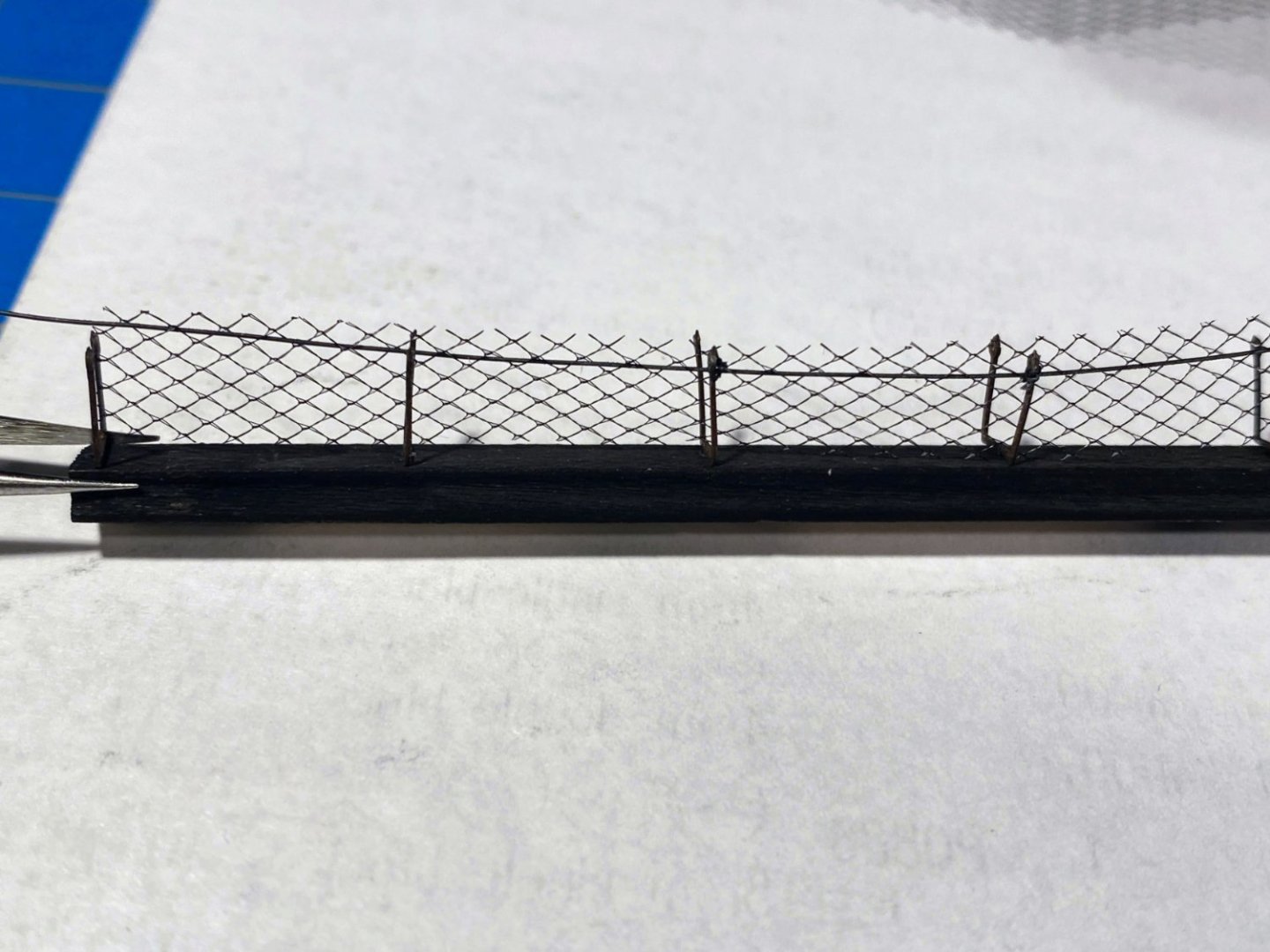
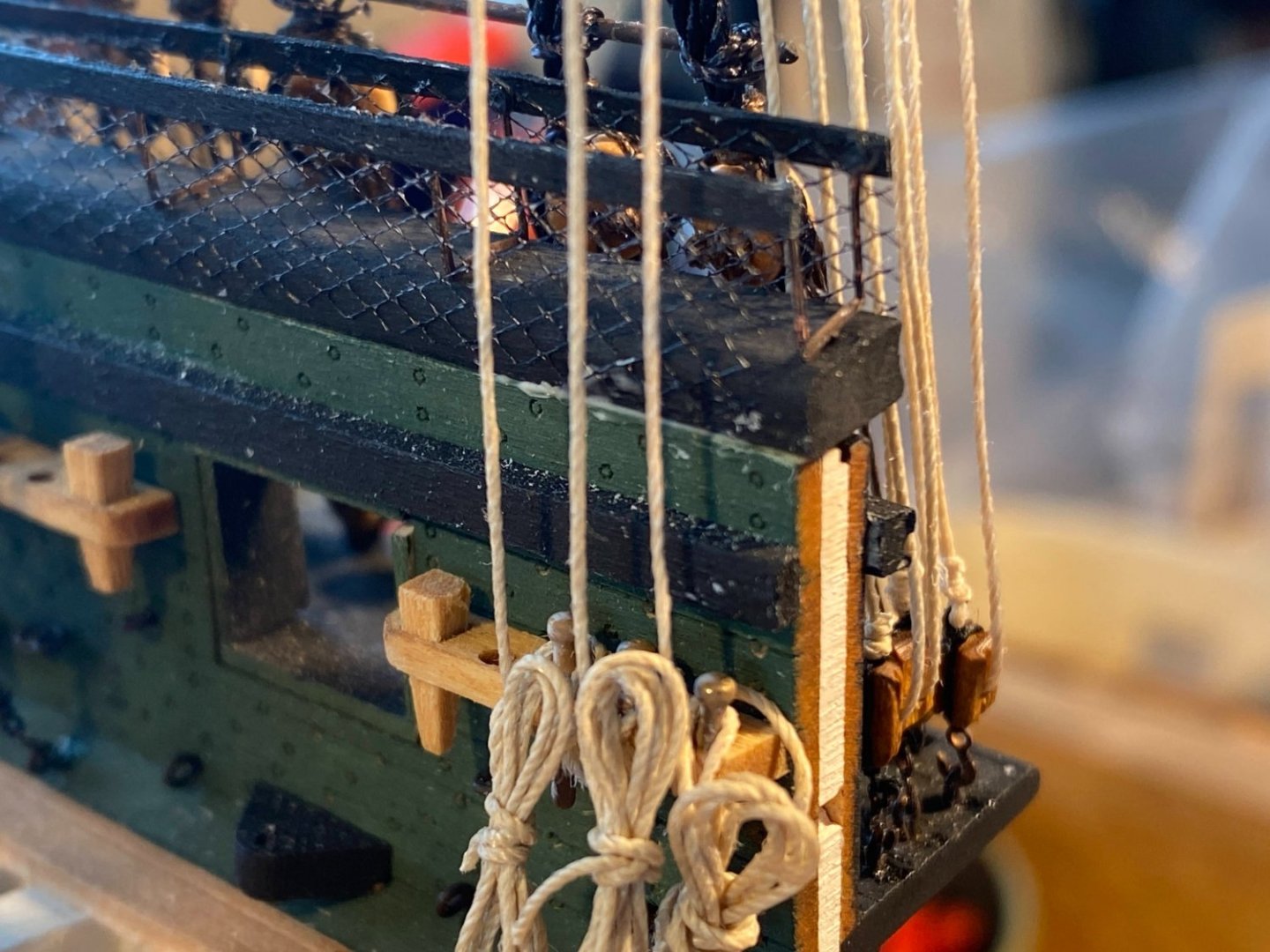
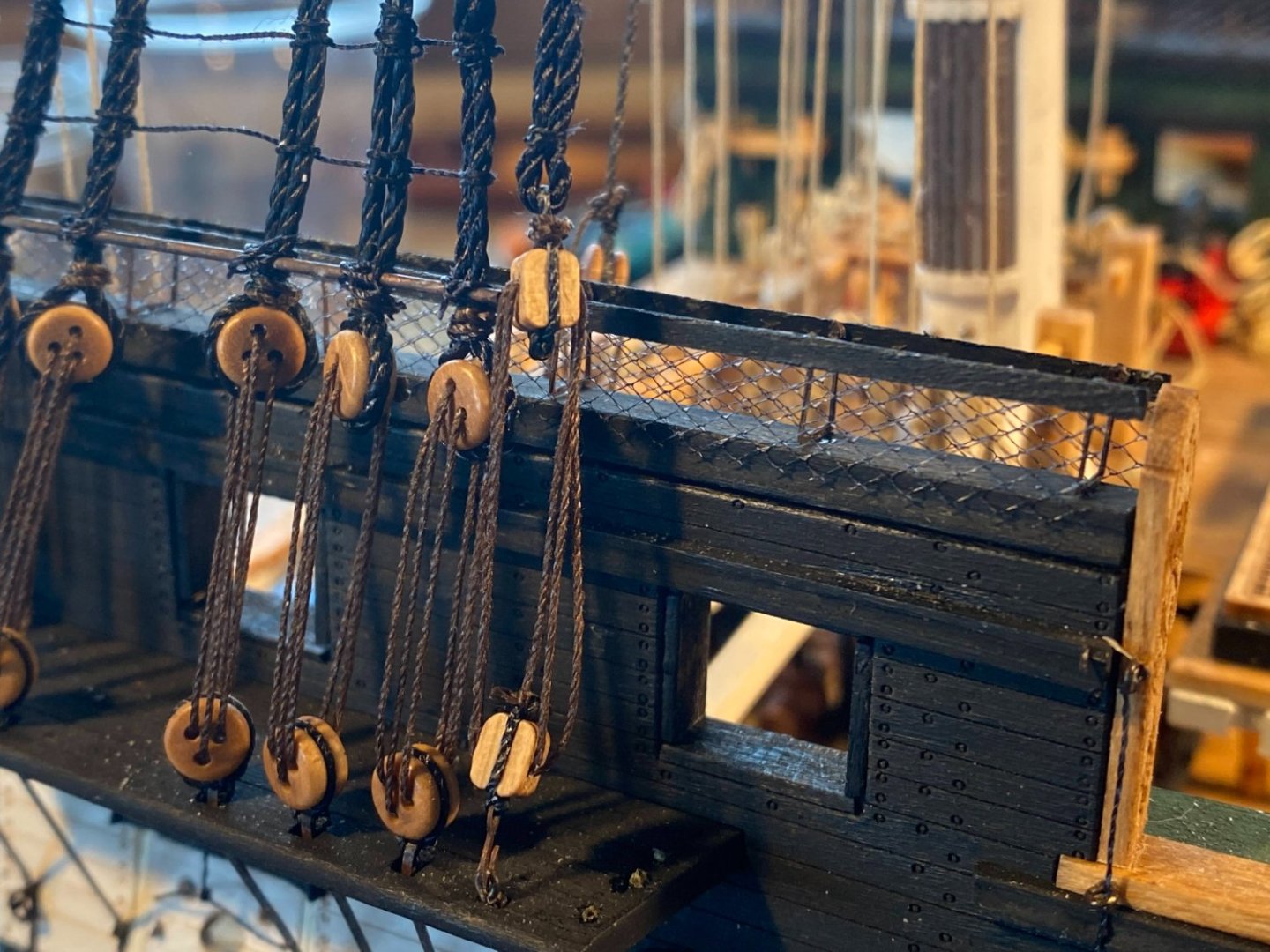
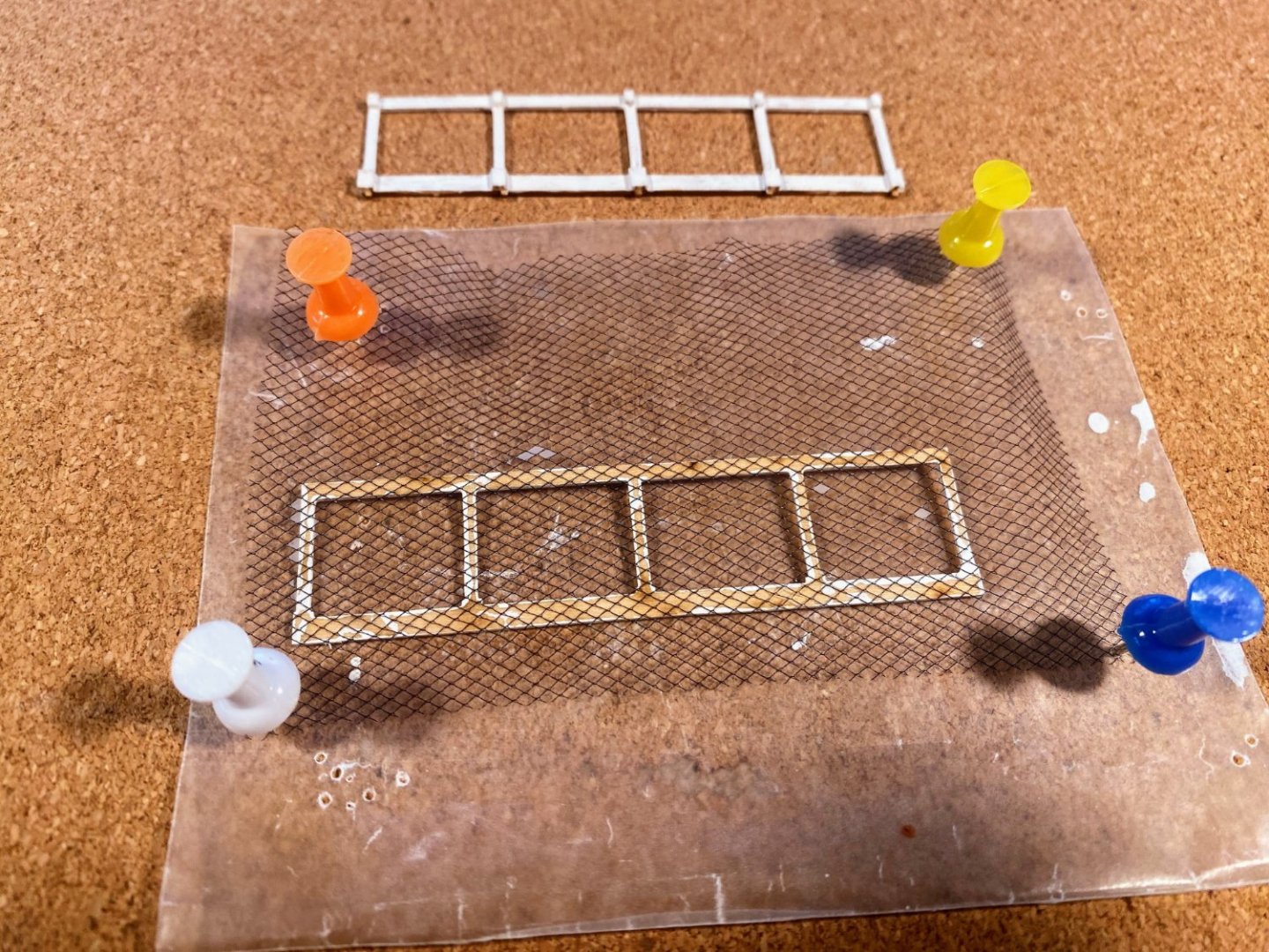
About a year ago I assembled one of two hammock rails. After gluing the hammock rail stanchions onto the previously painted cap rails, I then cut a piece of netting to the appropriate size, and led some thread through the netting and the eyes at the tops of the stanchions. I then ran another piece of thread through the bottom of the netting and tied it to the bottoms of the stanchions. None of this was easy to do, it took many hours, and I was not happy with the result. Strike one. I carefully stored this one away and left for another day the assembly of the other hammock rail. Well, another day has come. This time I had learned something about working with this netting material, from having put together the back rail on the fighting top. Coating the netting with diluted white glue makes it stiffer, easier to cut, and easier (but still not easy) to work with. One detail I learned is that you need to have some small pieces of paper towel handy to blot away excess glue; otherwise you end up with unsightly white flakes in some of the netting. This time I threaded the netting with thin wire rather than thread . . . wire which despite my fears to the contrary, I was able to straighten pretty well. The result was better than my effort from a year ago, but I was still left with an unsightly upper edge of netting . . . a bunch of exposed diamonds I found almost impossible to cut away cleanly without cutting the diamonds I had so carefully threaded the wire through. Strike two. My third effort was much better; if not a home run, at least good for extra bases. This time I used wood glue to glue a 1/32 x 1/16 strip of wood to the top edge of a cut strip of netting. I did this on top of wax paper, which peeled away pretty cleanly when the glue was still a little bit tacky. That small strip of wood nicely hides the upper edge of the netting. I then carefully twisted each stanchion so that the eye at the top ran fore and aft rather than athwartships. Then I put a tiny drop of wood glue in each eye, and glued the wood strip and netting to the outside of the stanchions. To be able to apply some pressure while the glue dried, I snuggly fit a strip of wood into the space between the inner and outer stanchions and slipped a strip of wax paper between the stanchions and that strip. I should have taken some pictures along the way but didn’t. In any event, the end result looked much better than my previous efforts. I did not do anything with the lower edge of the netting; it simply lies nicely against the edge of the cap rail, without any glue. Since it is black on black, from viewing distance the netting is almost invisible lying against the cap rail (or maybe it’s just my eyes). The Constitution as she exists today, and presumably previous iterations, has cable running through the top of the netting. But in this case I am happy to sacrifice some historical accuracy for something that leads to a better looking model.
- 163 replies
-
- 5
-
-
- Model Shipways
- Constitution
- (and 2 more)
-
Nic, that Wyoming is one spectacular model. I wonder how it got its name. I've driven through Wyoming a number of times, and I've never seen a maritime museum there. I understand it's maritime history is pretty scant. 🙂 Also, nice work on the new website.
-
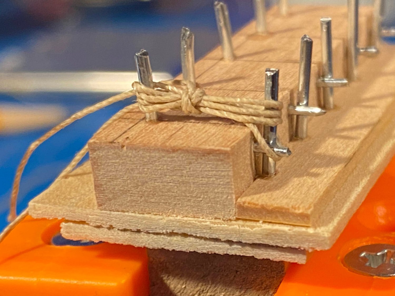
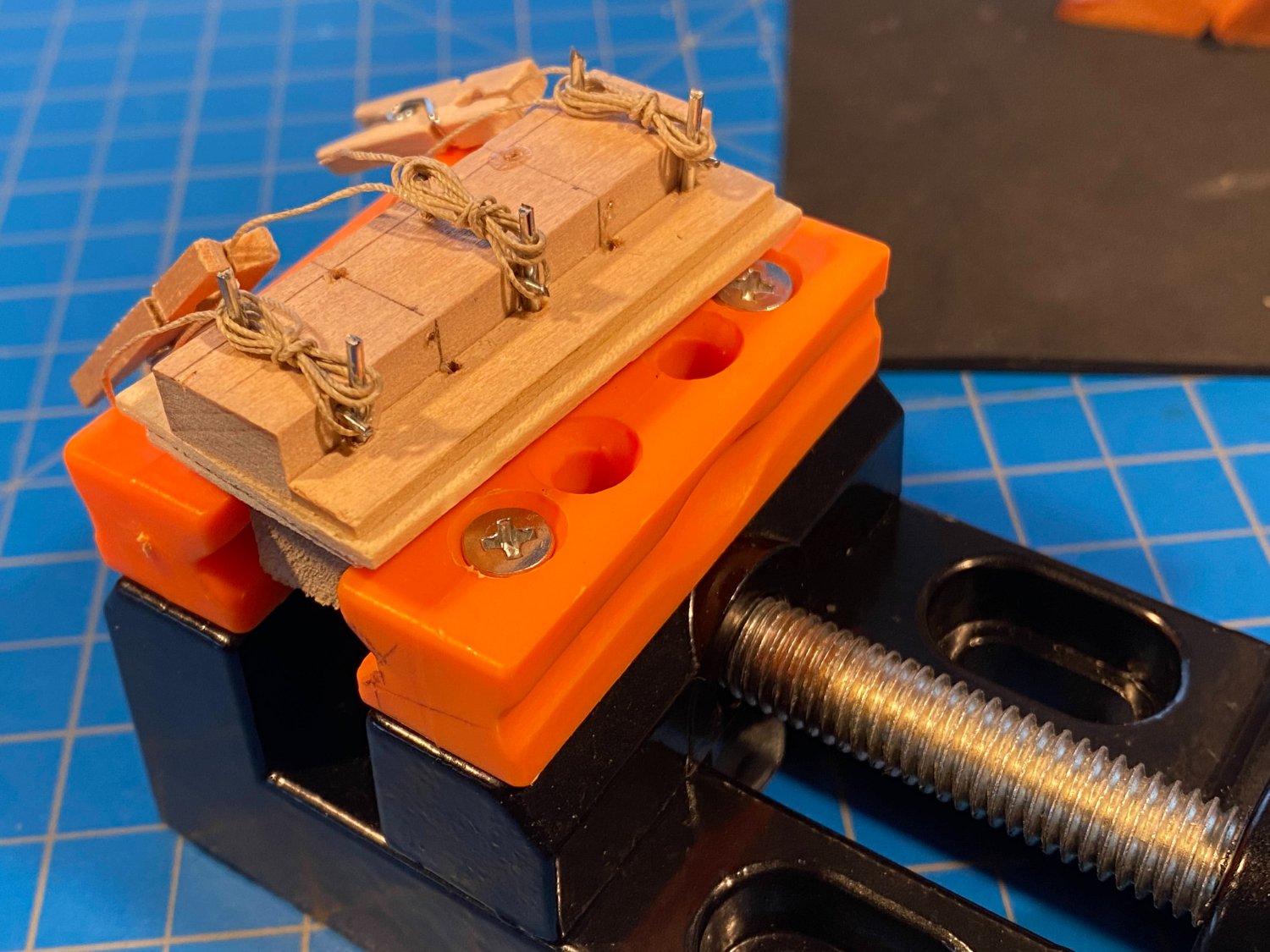
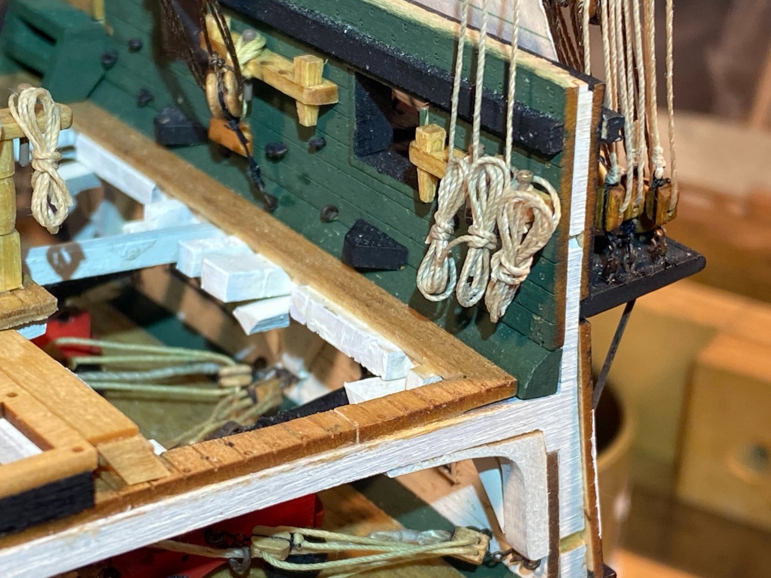
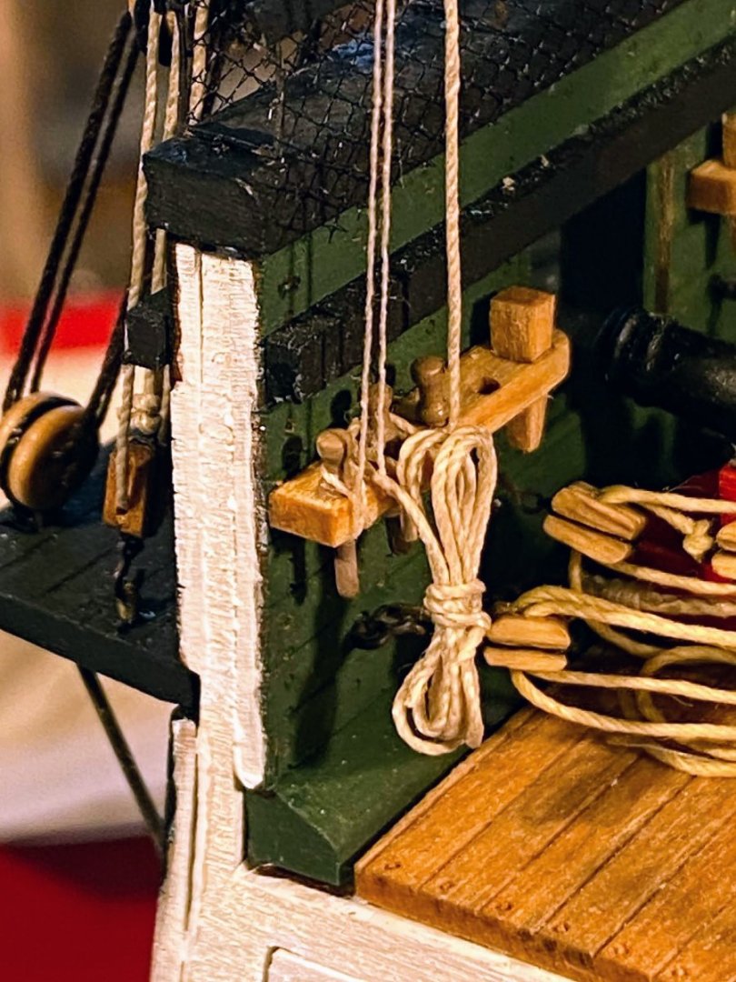
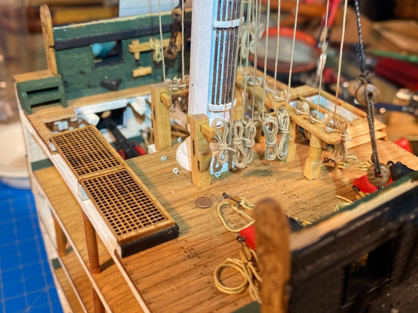
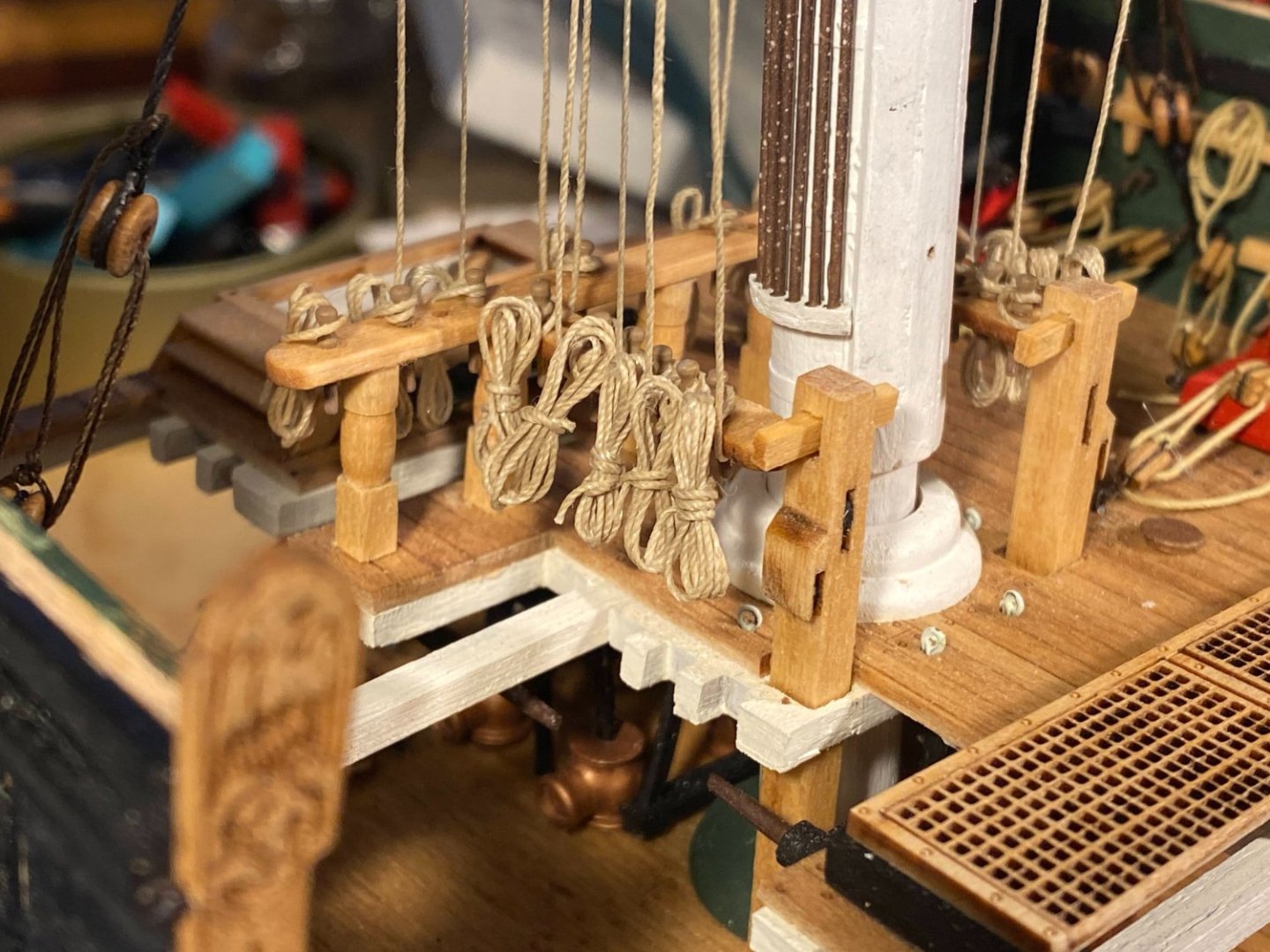
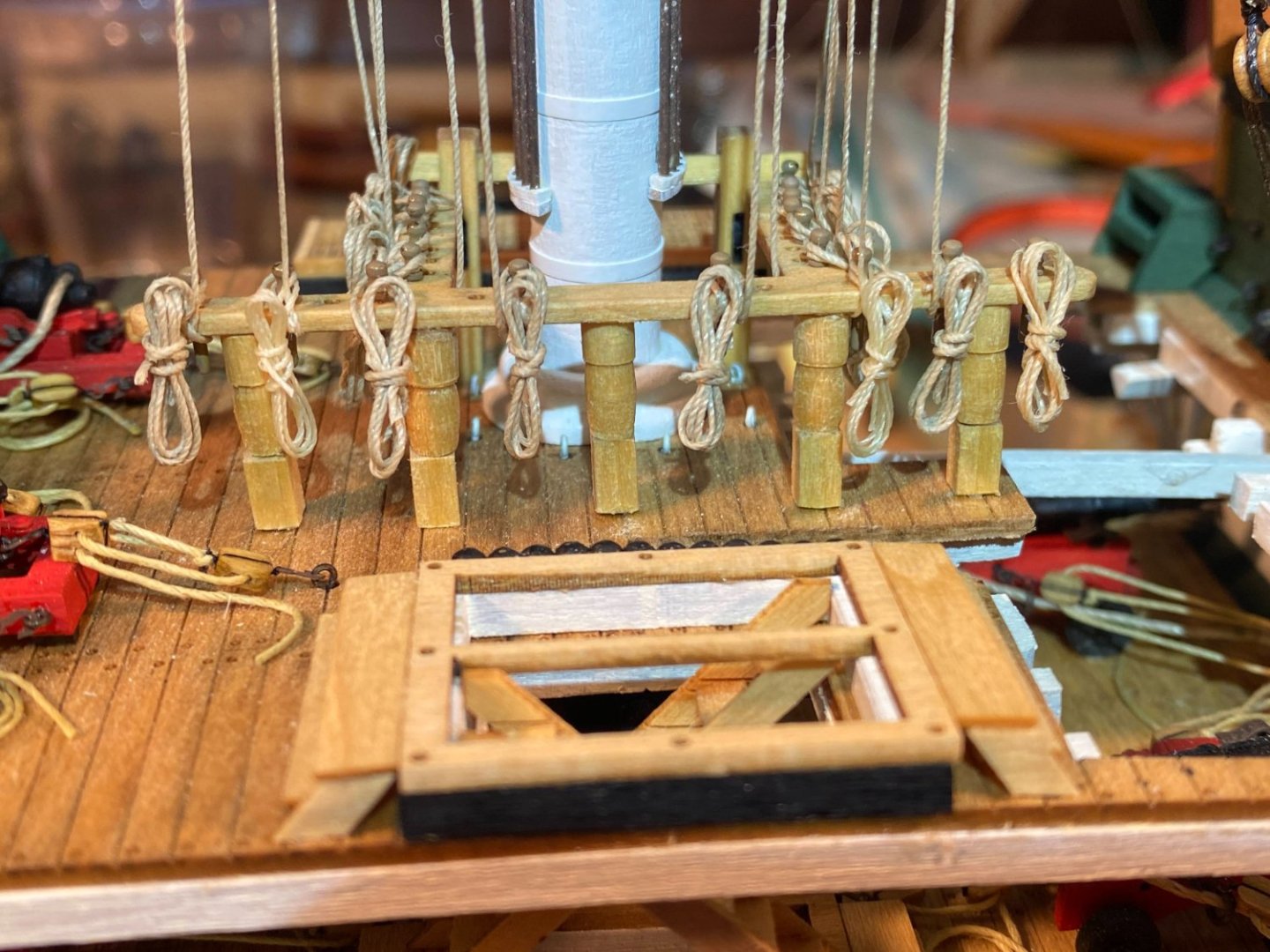
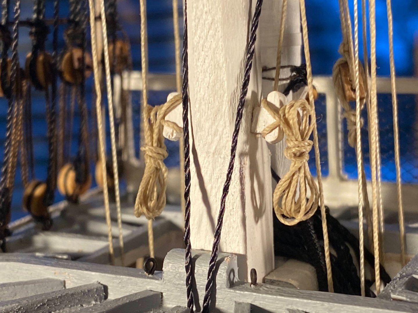
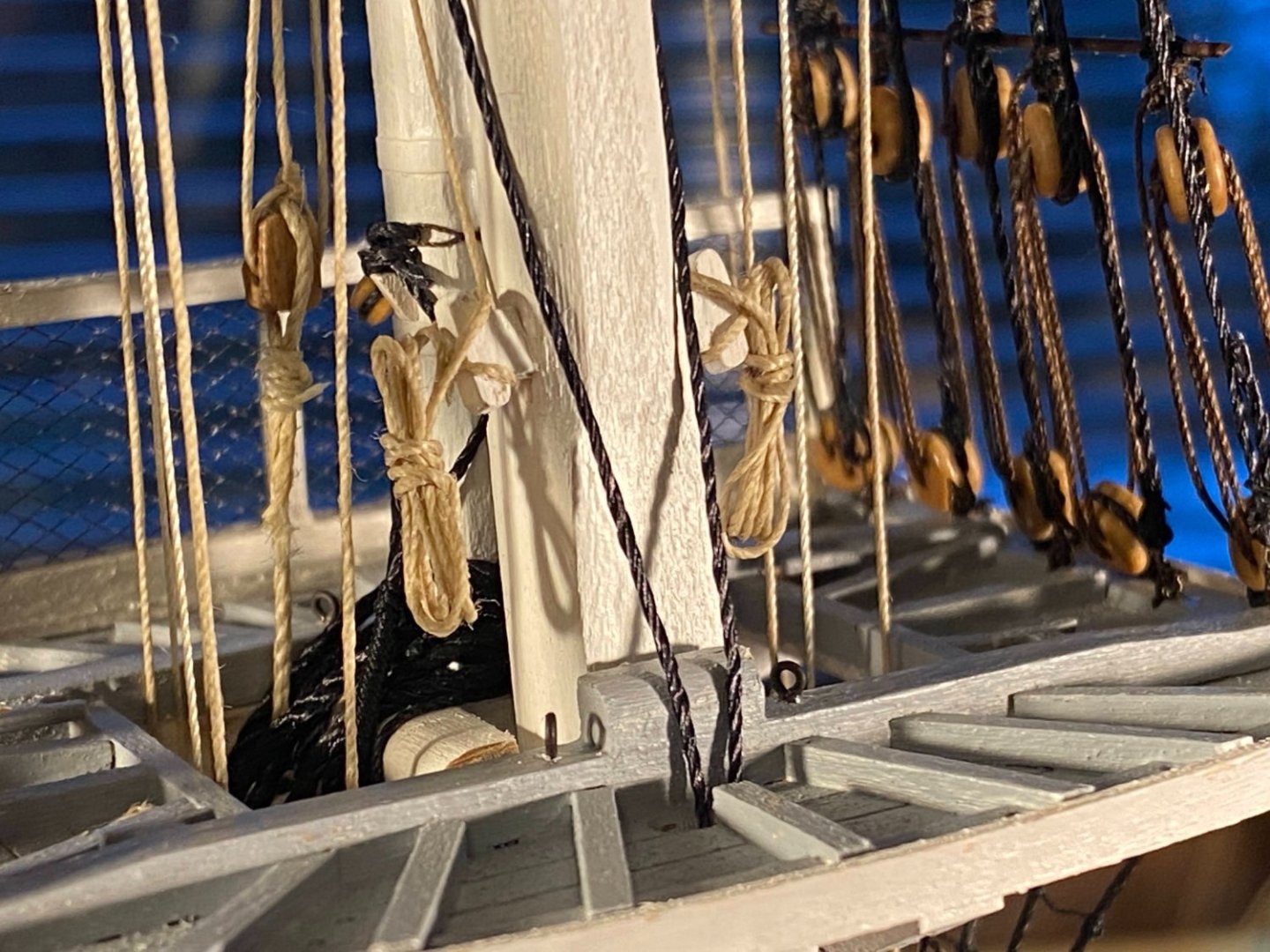
The rope coils project began with making a jig, inspired by one that is well explained and photographed on the Crafty Sailor website. I got ambitious and made one on which I could put together 5 coils at a time. Unfortunately they were too close together, and while making one coil I found myself snagging the threat on the posts for the neighboring coils. So I pulled the posts for two of them out and turned it into a 3 coil jig. The posts were cut from a large paper clip. I cut slits in the base to secure the end of the rigging thread, but those didn’t hold well at all. Clipping a mini-clothespin to the end worked a lot better. I then wrapped two coils around the vertical posts, then wrapped the third coil around the vertical posts at the top of the coil, and the final two coils around both vertical posts. I then took two or three wraps around the coils and secured it with a half hitch at the end. For some reason the latter wraps proved to be more difficult than I expected, and for the most part they don’t have a consistent look from coil to coil. As a young adult sailor some decades ago I easily coiled thousands of lines over the years, but rope and rigging thread just don’t behave the same way. Also, getting the coils to hang naturally (vertically) was sometimes problematic. Unfortunately I didn’t take any photos of the numerous odd ways I leaned things against the coils to get them to hang vertically, soaking the loop around the belaying pin with diluted white glue and letting it dry. There were two empty belaying pins on the athwartships part of the fife rail, so I hung a couple of extra coils on them. I also hung coils on the cleats on the mast I secured the trusses with. And now some pictures . . . Next project is completing the hammock netting and rails I started but never finished maybe a year or so ago.


- 163 replies
-
- 6
-
-
- Model Shipways
- Constitution
- (and 2 more)
-
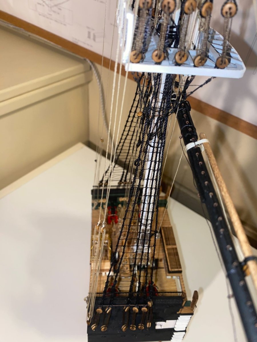
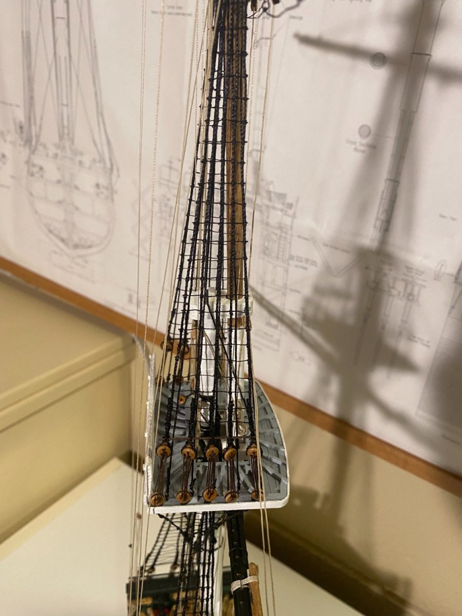
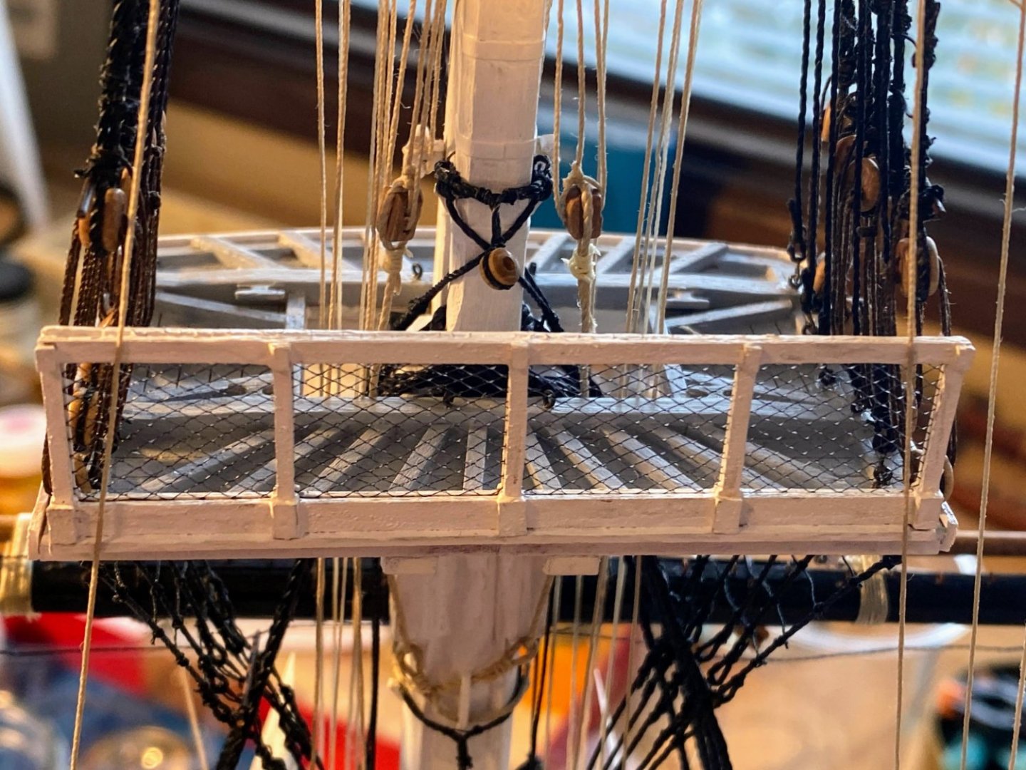
In addition to the usual slow down in the shipyard during holiday season, this year I’m also distracted by the World Cup (sad day yesterday for English fans), and locally I have already used my snowblower more this year than the last two or three put together. And winter is still 10 days away! I did not build and install the aft guard rail on the fighting top when instructed, figuring it would get in the way of stringing the running rigging, and I think that was a good decision, although the rigging now made the job of installing the built rail a little more challenging. The instructions suggest putting the netting material on top of wax paper and giving it a coat of diluted white school glue, then pressing the aft frame against the wet glue. I was afraid the wax paper would be difficult to remove once the glue dried, and I took a different approach. I laid one frame on top of wax paper (to protect the surface below), then stretched the netting across that frame, and then gave everything a good coat of glue. When that was dry, I glued the other frame on top of the first frame with the netting sandwiched in between. That worked pretty well. The reason I wanted the netting coated with diluted white glue was to stiffen it and eliminate the creases in the netting material (since it was folded as supplied). With a new sharp blade in my knife, I cut away the excess netting. The material cuts much more cleanly when it has been stiffened with glue, but after cutting there was still a bit of stubble left. I applied another coat of glue around the frame, then a coat of pain, and then gave it another cut. The result was not as clean as I had hoped, but from any reasonable viewing distance it looks pretty good. A challenge I had not anticipated was that the aft deadeyes, solidly glued in place months ago on the fighting top deck, get in the way of the assembled guard rail. I had to do some cutting and shaving at each end of the guard rail base and the outer stanchion of the rail so that the rail would fit. Nevertheless the base sticks out beyond the aft edge of the deck, rather than being flush with it, but that was the best I could do. I am also getting started with the lower ratlines, another project I did not do when directed in the instructions, thinking they would get in the way of the stringing of running rigging. In retrospect I’m not sure that was a good decision, but rigging the ratlines is nevertheless progressing satisfactorily. Next post will cover rope coils.
- 163 replies
-
- 4
-
-
- Model Shipways
- Constitution
- (and 2 more)
-
Thank you Tim. That's very kind of you. But what I am able to bring to the conversation wouldn't be possible without the valuable contributions of so many who are better informed or more skilled than I am. Most recently that would be Henry (popeye2sea). The community created by these forums is incredible, and I owe a big thank you to all who have made it the great resource that it is.
- 163 replies
-
- 2
-
-
- Model Shipways
- Constitution
- (and 2 more)
-
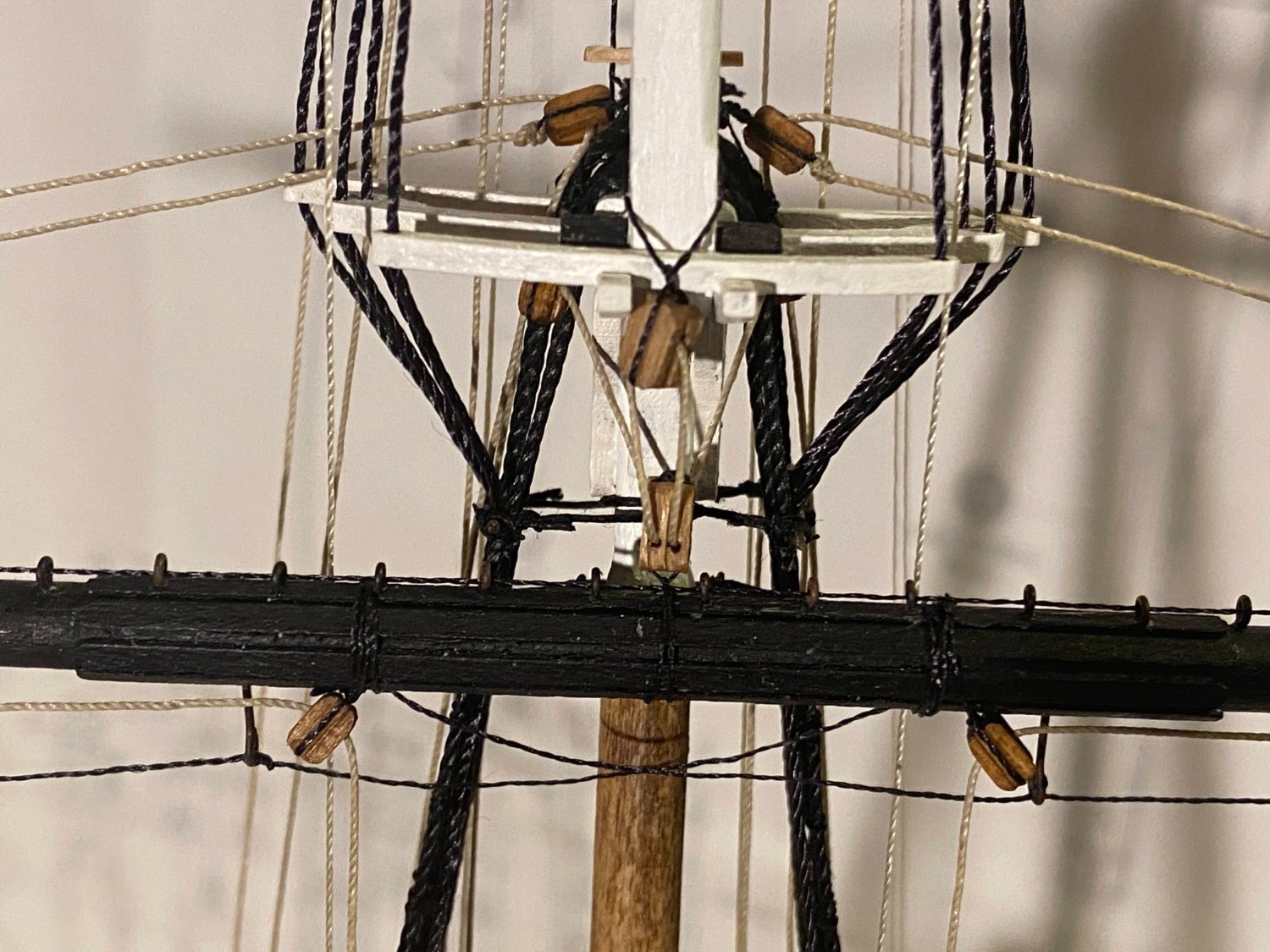
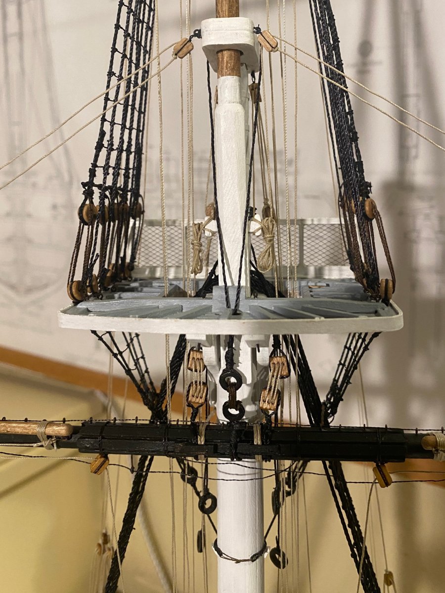
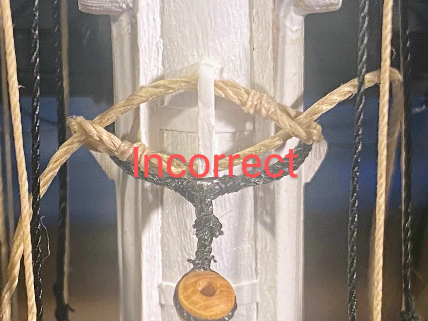
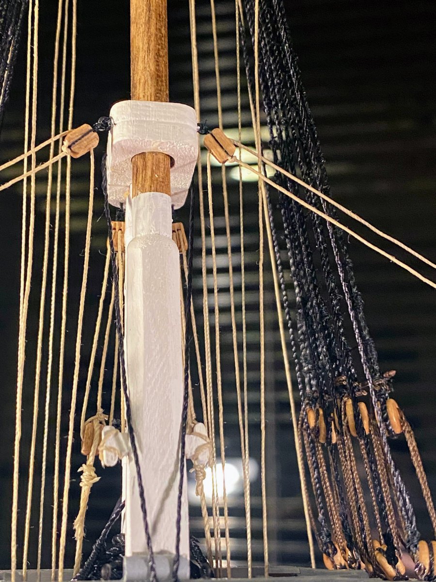
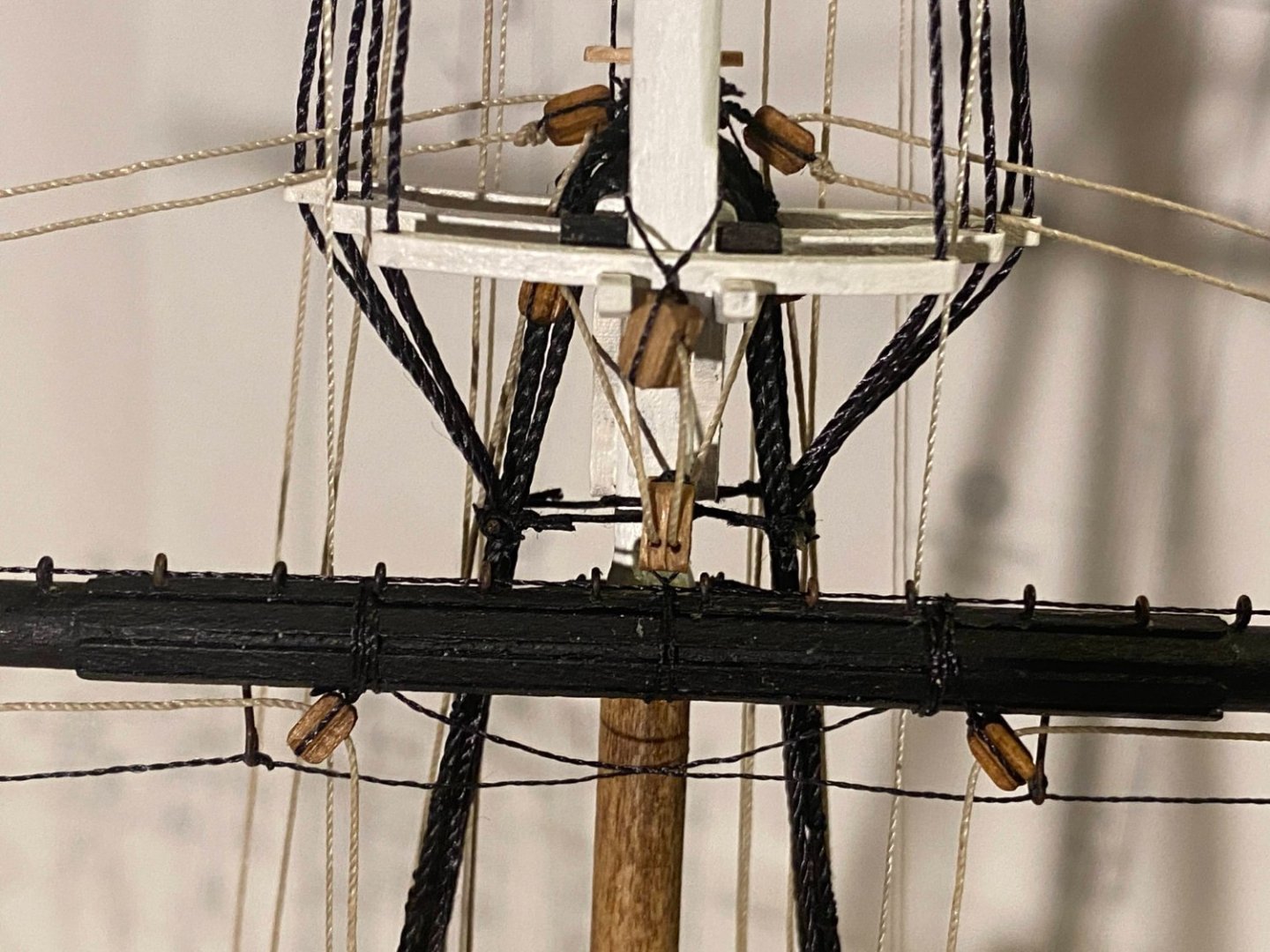
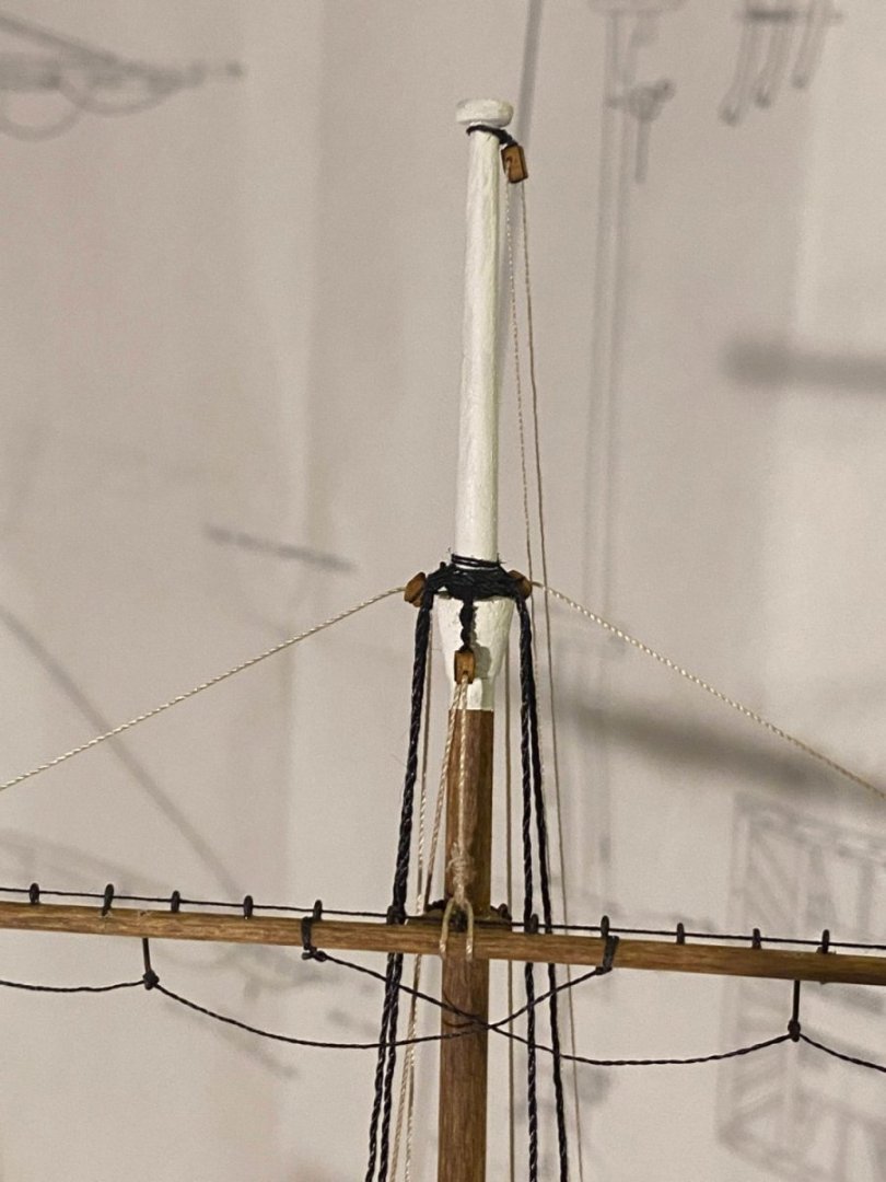
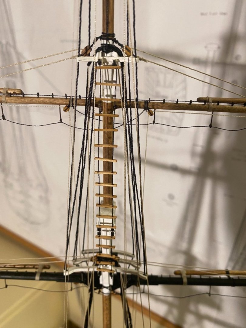
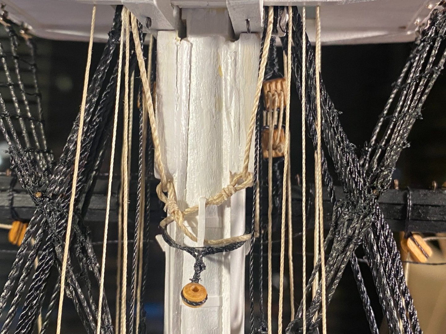
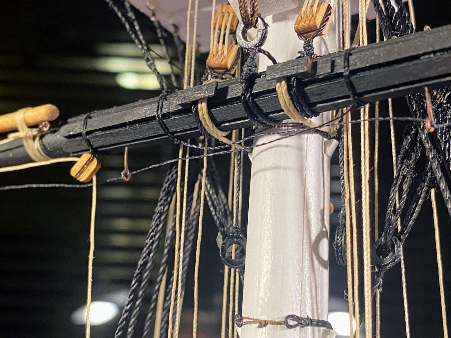
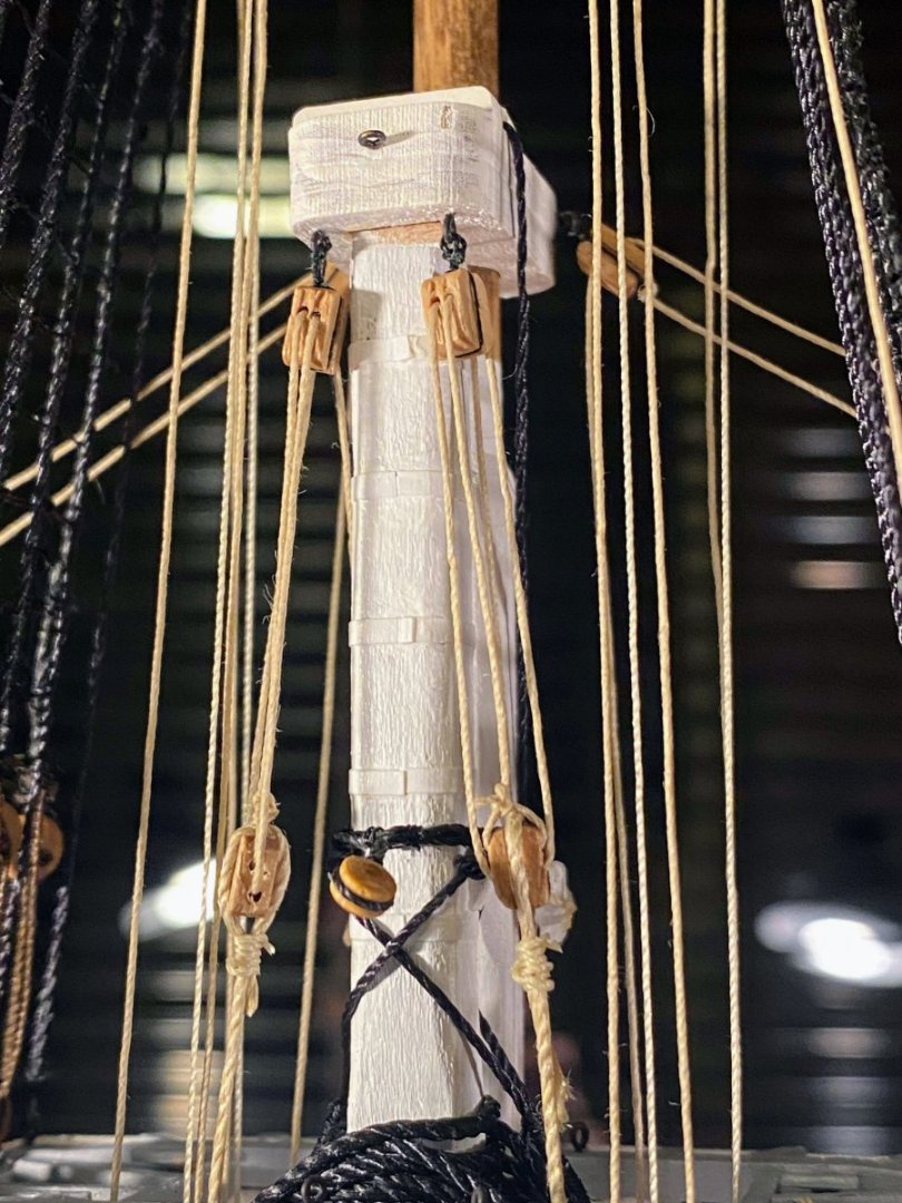
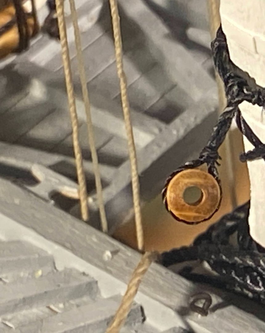
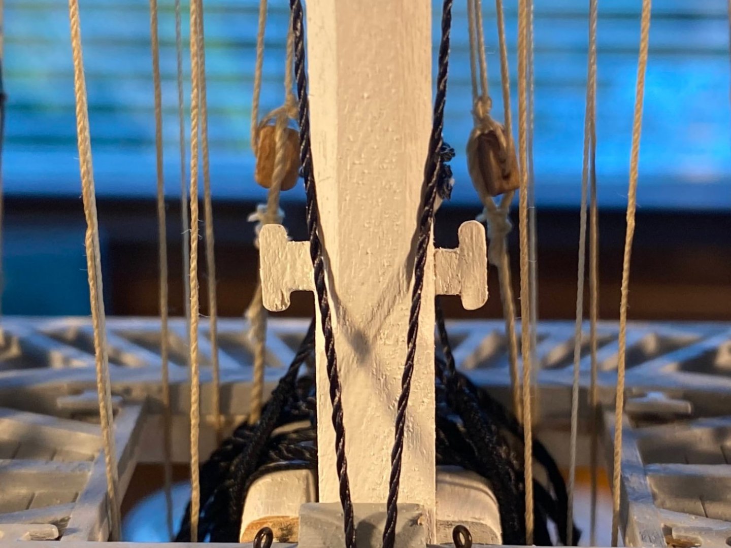
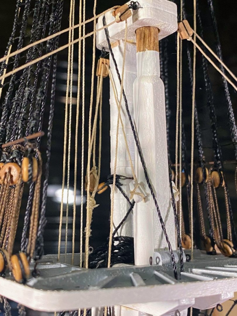
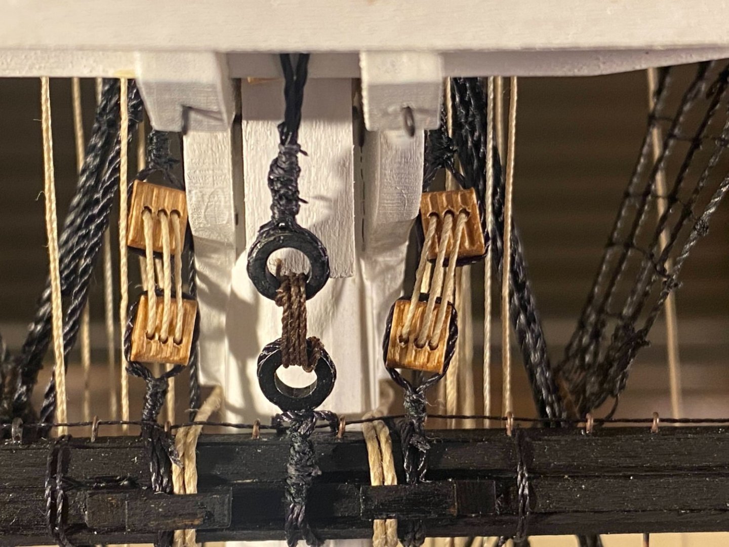
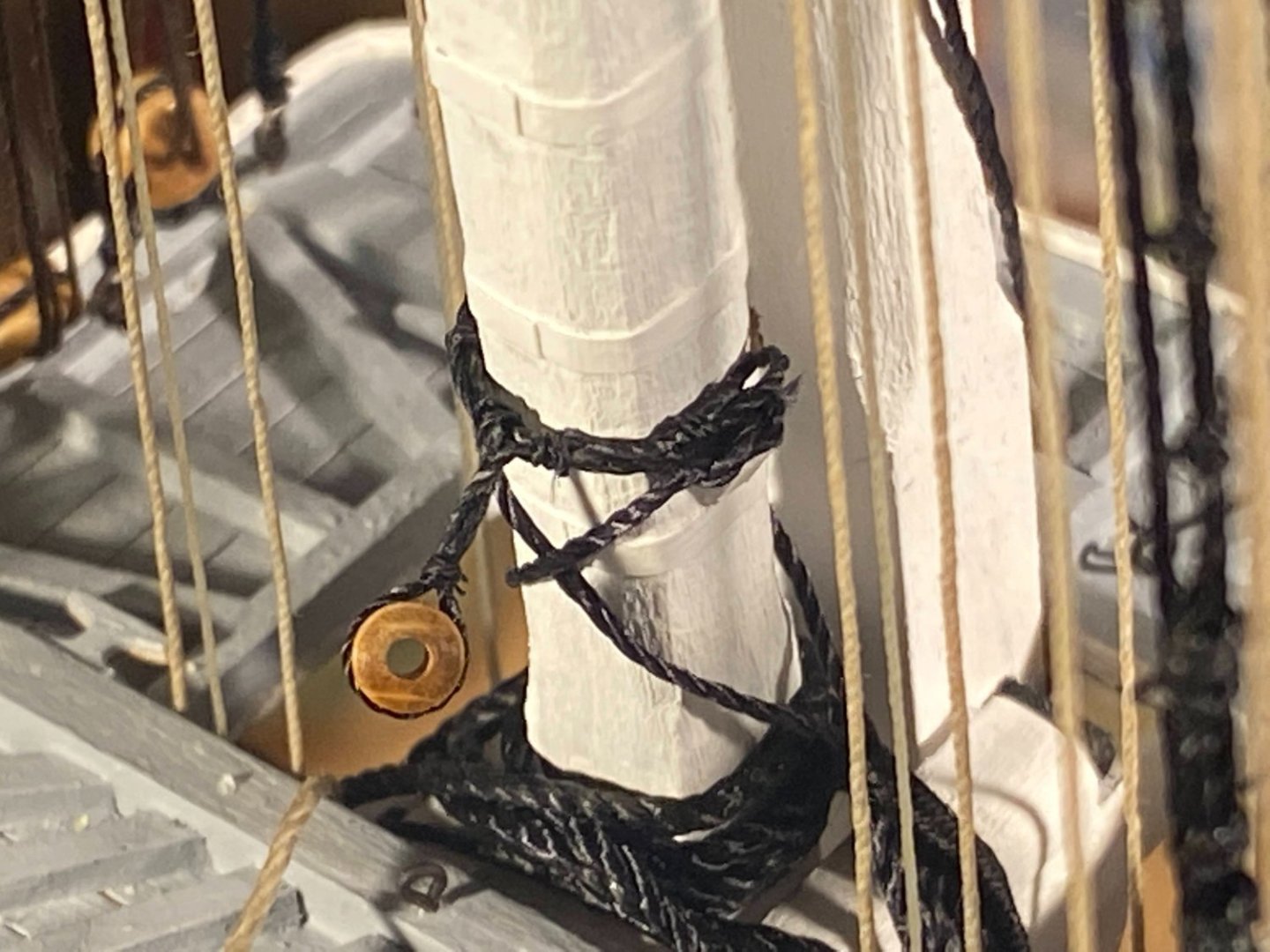
The lower end of each truss is fixed to the mast at a fairlead glued to the back side of the lower mast while building it. Each line has an eye at the end through which the other line passes through. The kit supplies britannia metal circular thimbles for each eye, but a smaller, thinner, tear-shaped eye would probably be more accurate. Such a fitting is not supplied and would probably be too small to work with. I simply seized an eye, without a fitting, at the end of each line. A couple of weeks ago there was an exchange of posts in which popeye2sea pointed out that the way the instructions explain the trusses is not correct. At the time I didn’t mention this, but I had already rigged the mast end of the trusses as instructed; that is, each line ran through the other line’s eye immediately after leaving the fairlead. It wasn’t difficult to undo what I had done and rerig it correctly; that is, each line left the fairlead, went forward to wrap around the yard, then went aft again to run through the eye in the other line, then up through the open space in the fighting top. Above the fighting top, each line ends with a single block, to which is attached another line. That line becomes part of a tackle, going up to a double block secured to an eyebolt under the mast cap, back down to the single block, up to the double block, and down to a cleat previously installed in the deck of the fighting top. At least in my case, that cleat was installed with no expectation that anything would be belayed to it. It is tiny, flimsy and hard to get to. I decided the line could be belayed just as plausibly to a cleat attached to the topmast. Two pairs of laser cut cleats were glued to the fighting top, but a third pair was left unused, and I carefully glued them to the sides of the mast. What concern I had about these cleats being flimsy was proved justified, as both broke when I tried to belay the lines to them. They are cut from 1/32” thick stock, the grain runs across the tiny throat of each one, they both broke there. So I pried the remaining cleat bases off the mast and built new, heftier cleats from 1/16” square stock. The resulting cleats are too big for scale and as can be seen in the photo below, I didn’t get the throat centered on one of them (later corrected), but such flaws should be largely hidden by a belay and a rope coil. Now on to a fairly lengthy list of things I didn’t do earlier in the build . . . such as lower ratlines, fighting top railing, hammock rails, etc. The end is in sight!


- 163 replies
-
- 4
-
-
- Model Shipways
- Constitution
- (and 2 more)
-
Thanks Brian. I too frequently dip the end of a thread into some CA, but was different here was the length of thread coated in CA. Usually I dip no more than half an inch or so. Your Cairo build is magnificent.
- 163 replies
-
- 1
-
-
- Model Shipways
- Constitution
- (and 2 more)
-
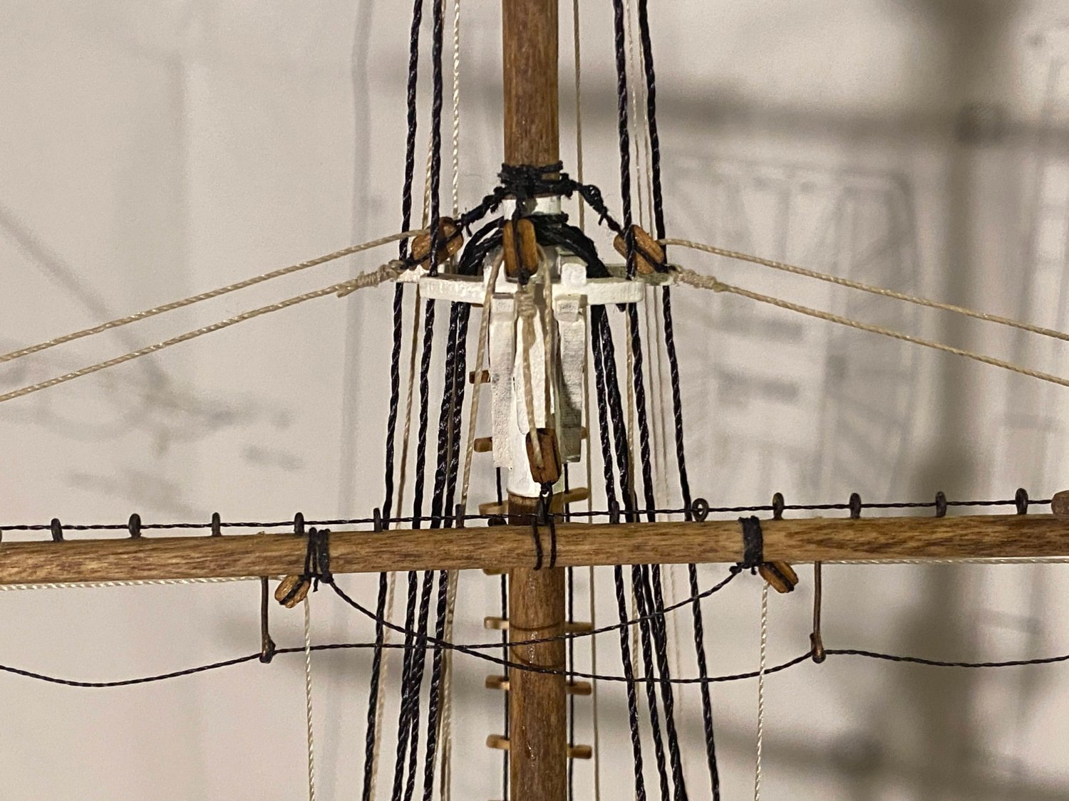
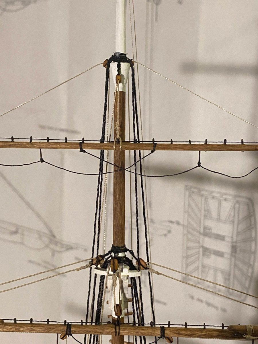
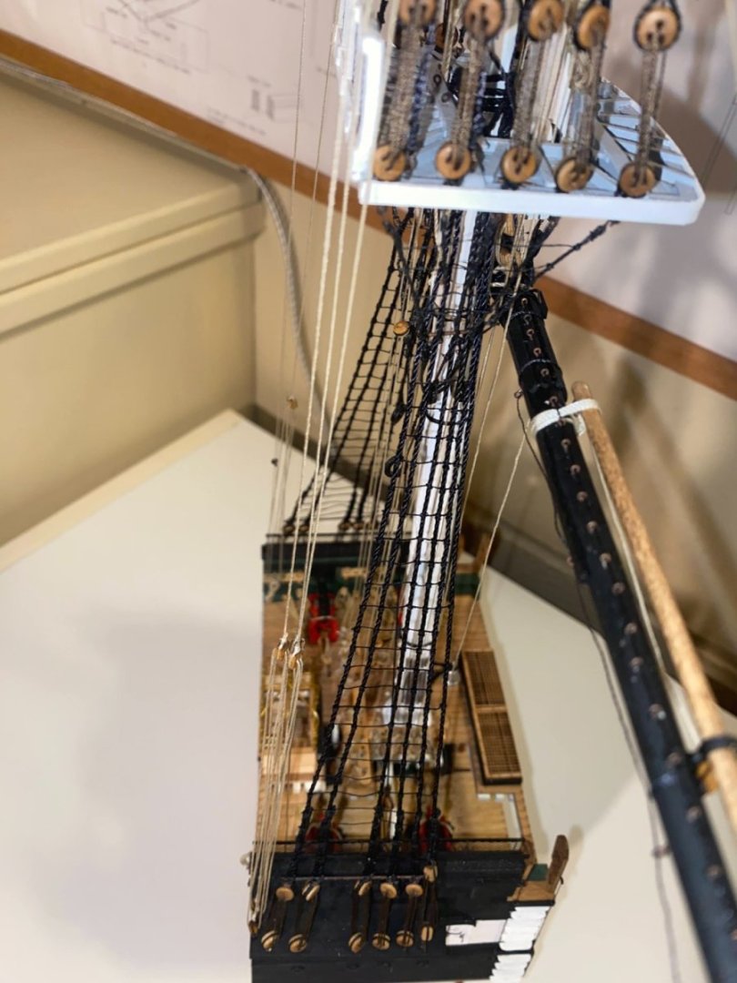
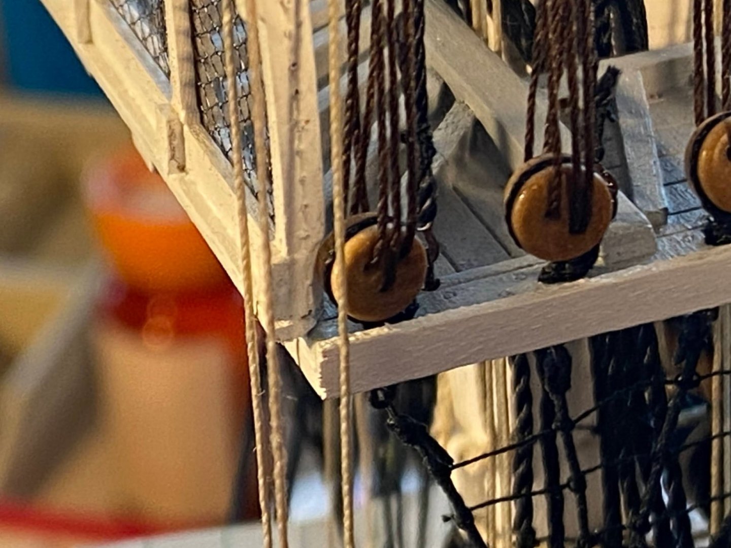
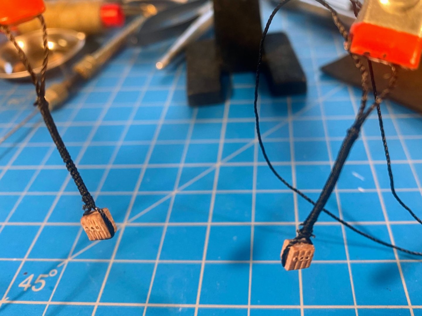
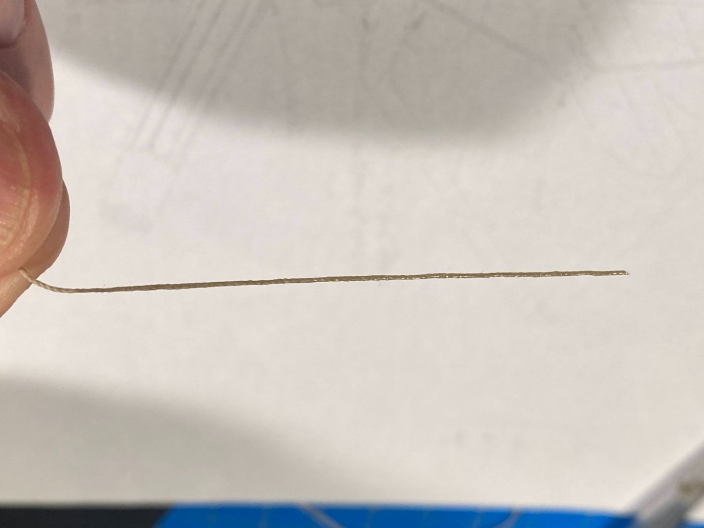
You're right Bob, the rigging gets complicated and crowded. As I've said before, I'm glad I'm doing only one mast. I started rigging the jeers and the truss more or less at the same time, trying to figure out which one would get in the way of the other the most, and leaving that tackle for last. That led me to finishing the jeers first, which will be the subject of this post. Each jeer is a pair of triple blocks, one lashed to the top of the yard, the other just above it, hanging from the mast. I made a pair of lanyards for the latter, by first tying a block to the middle of about 8 inches of thread. I then served the two lengths of thread together, for about an inch above the block. Some may have noticed that I did not serve any of the shrouds where they wrap around the mast. I don’t have a serving machine, and carefully wrapping thin thread around a length of thicker thread at least a couple of dozen times seemed incredibly difficult and tedious. But trying it on these lanyards was a lot easier than I expected. I secured each end with a clove hitch, then gave each serving a healthy dose of diluted white glue. The next challenge was threading the line through each pair of blocks. Things are pretty crowded where the mast and yard come together, and my attempts to get my thumb and fingers in there all failed. What worked was creating a long “needle” with a dose of thin CA on about 2½ inches of the thread to be rigged, stretched straight between a couple of mini clamps. I left about an inch at the end of the thread unglued, so it wouldn’t be glued to the clamp, then cut that end off. The needle enabled me to get the thread through the blocks from the aft side, and it worked! I hung each lanyard loosely around the mast, not tying it until I had the block rigged to its counterpart. They can be seen crossing each other in the second picture below. Finally securing them after the blocks were rigged made it easier to adjust the distance between the blocks, and for whatever reason I rigged the first pair (left in the picture below) about half an inch apart. I think that may have been a mistake, as they would have been better aligned if they had been rigged closer together, as shown on the plans. Especially the blocks on the right don’t line up very well. Finally when I brought the ends of the lines down to the fife rail, they crossed behind the already installed running rigging, running from the upper block just forward of the mast to the aft end of the fife rail. To avoid rubbing up against those other lines, I brought these lines down to the back side of, and under, the rail. In the picture of the blocks above, you can see that I have wrapped the pair of trusses around the yard. That and the rigging of the truss tackles will be the subject of my next post.
- 163 replies
-
- 3
-
-
- Model Shipways
- Constitution
- (and 2 more)