HOLIDAY DONATION DRIVE - SUPPORT MSW - DO YOUR PART TO KEEP THIS GREAT FORUM GOING! (89 donations so far out of 49,000 members - C'mon guys!)
×


Tomculb
-
Posts
345 -
Joined
-
Last visited
Content Type
Profiles
Forums
Gallery
Events
Everything posted by Tomculb
-
 Thanks Josh. I wish you were still posting your log, showing me the way 😃. I assume you've realized that available time is finite, and as between writing and building, you choose to build. Good choice.
- 206 replies
-
- 1
-

-
- Endurance
- Shackleton
- (and 2 more)
-
About a year ago, I finished my build of Model Shipways USS Constitution cross section. A link to my blog is in my signature block below. I found it to be a lot of fun and a bit challenging at times. No question planking a cross section hull is pretty simple (unless it is a cross section of the bow), but the rest of the build provided lots of varied opportunities to learn. The mast and rigging (especially rigging) took me the better part of a year to complete (but I'm not a speedy builder). All of my builds have been (and always will be) great learning experiences, and my Connie was no exception.
-
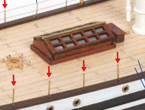
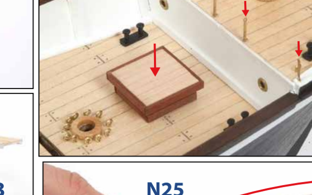
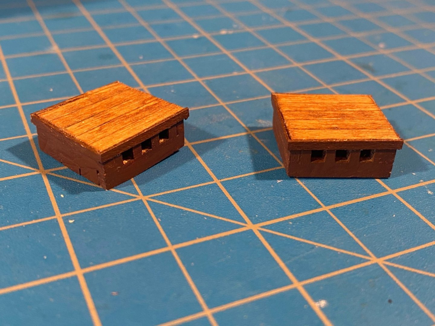
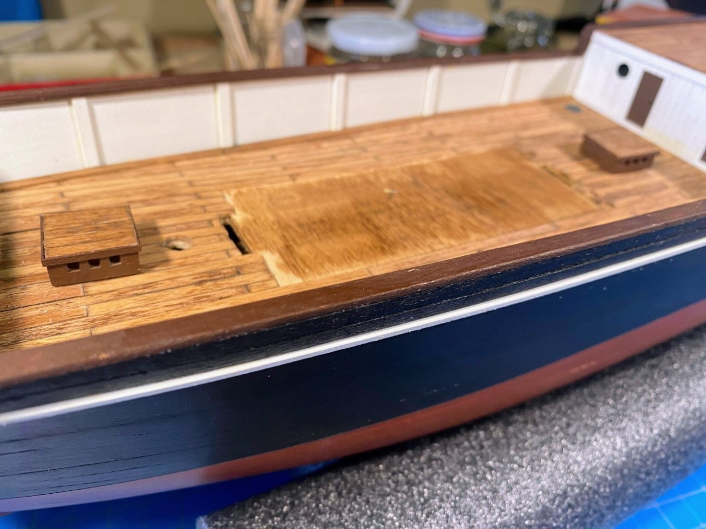
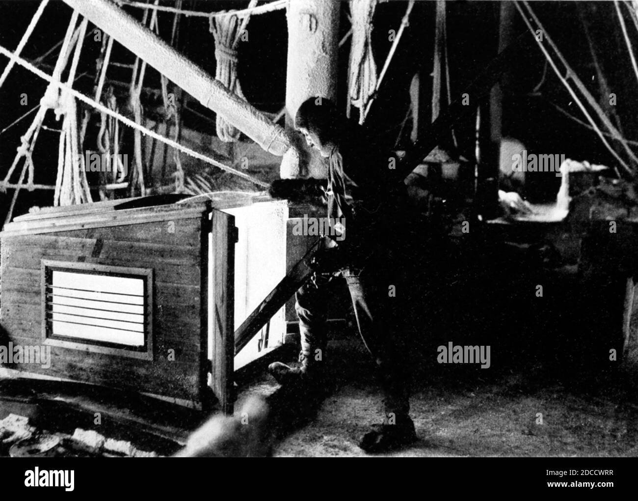
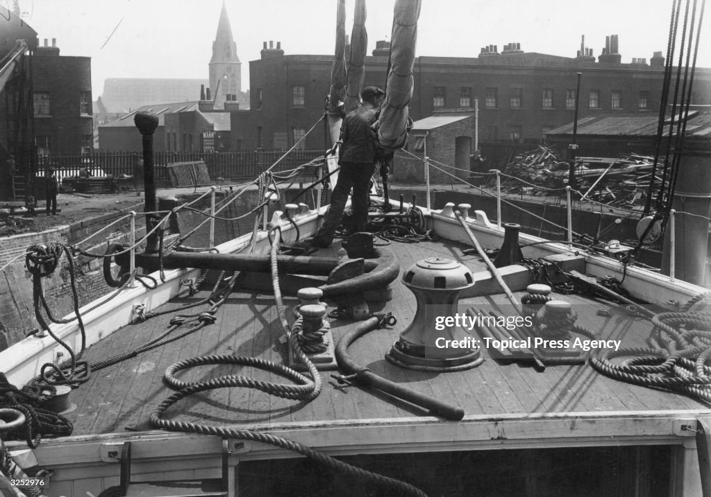
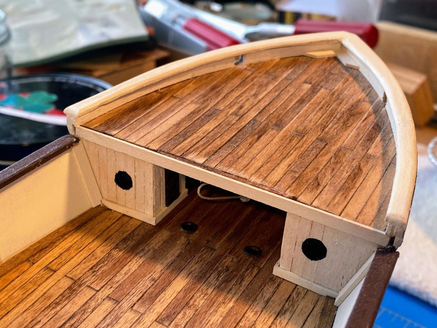
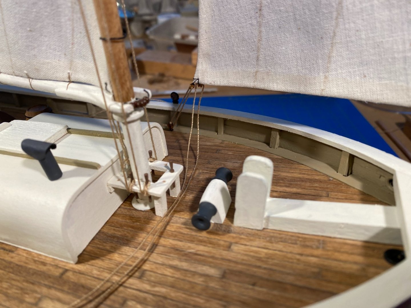
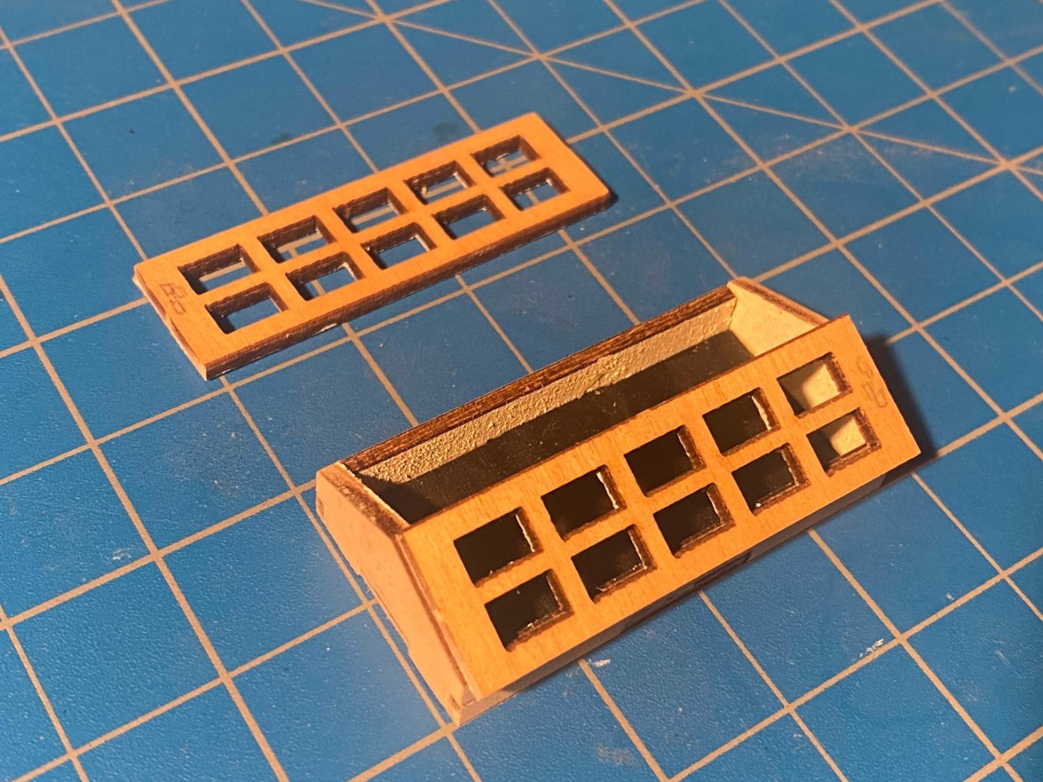
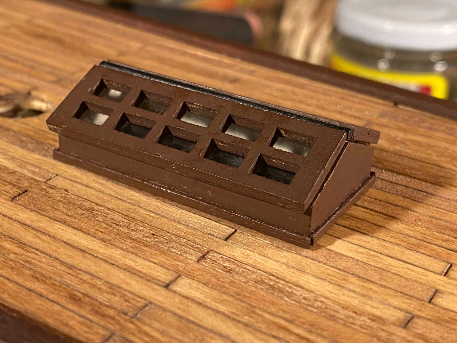
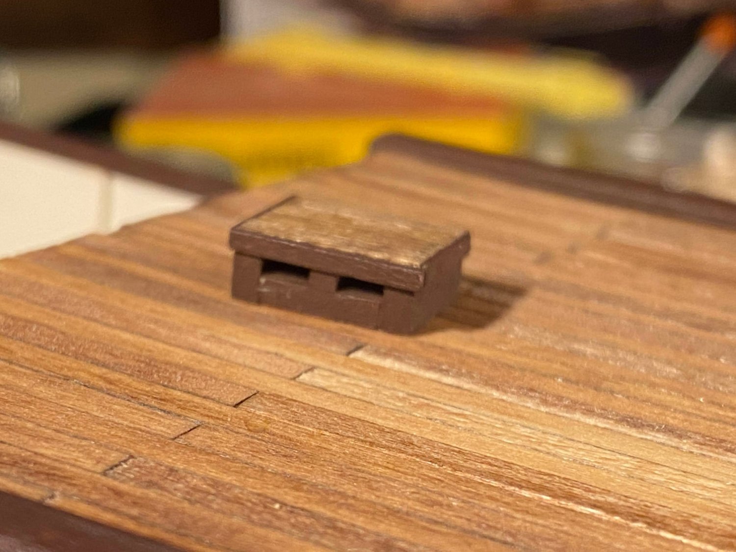
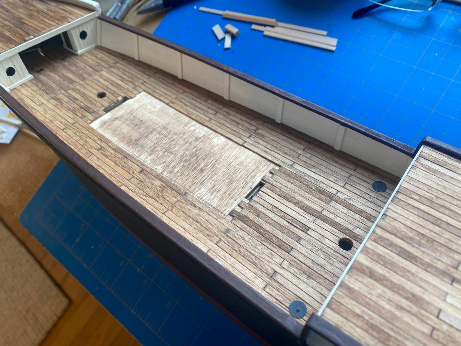
The skylight between the smokestack and the mizzen mast is easily assembled from laser cut pieces. OcCre also supplies a thin piece of acetate to simulate glass in the windows. The photographic instructions have you paint everything inside white, but I chose to paint the walls white and the floor black, to simulate some depth below. I also painted the hinge black rather than leave it as exposed brass as OcCre would. The rest of the skylight is painted flat brown. OcCre also has you surround the base of this skylight and the ones I describe below with what I think (IMHO) is an oversized, unrealistic looking, trim or combing. I used some 1/16 x 1/32” (or a metric equivalent) veneer to make the combing around my skylight. There are two somewhat unconventional skylights, located fore and aft of the deckhouse. Unconventional in that they look like raised hatches with windows on the walls. Here (again IMHO) OcCre again overscales things a bit, with large combing and a thick roof piece with deck planking added on top. Given the small size of these things, I chose not to add any combing and to eliminate the separate (laser cut) roof piece, laying the planking directly on top of the walls. Stain on the roof planking is the same I used on the deck planking. The Frank Hurley photo below shows a large companionway structure leading to a ladder or stairway leading below decks. From what I have read, I think that was added after Endurance got stuck in the ice. The plans I have referred to several times in this log do not show any such structure. Instead they show another skylight, similar to but smaller than the ones described above, on the top of the deckhouse. OcCre supplies laser cut pieces to build this structure, but I chose to scratch build another skylight that conforms to the plans. In the photo below it hasn’t been glued to anything yet, as the deck house hasn’t been built yet.


- 206 replies
-
- 5
-
-
- Endurance
- Shackleton
- (and 2 more)
-
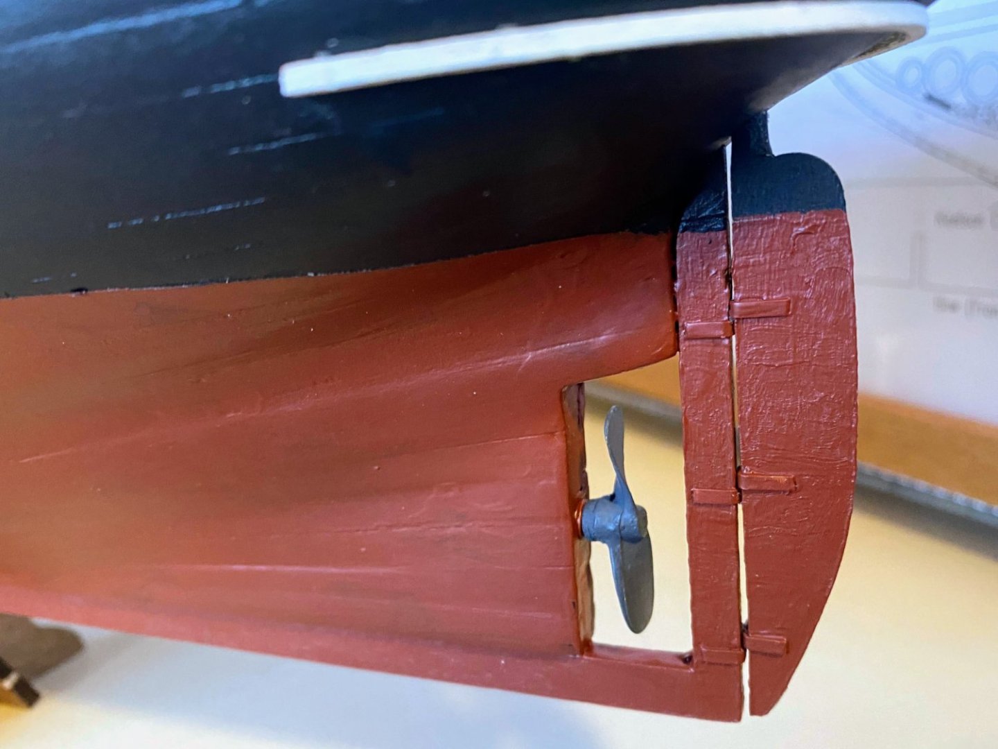
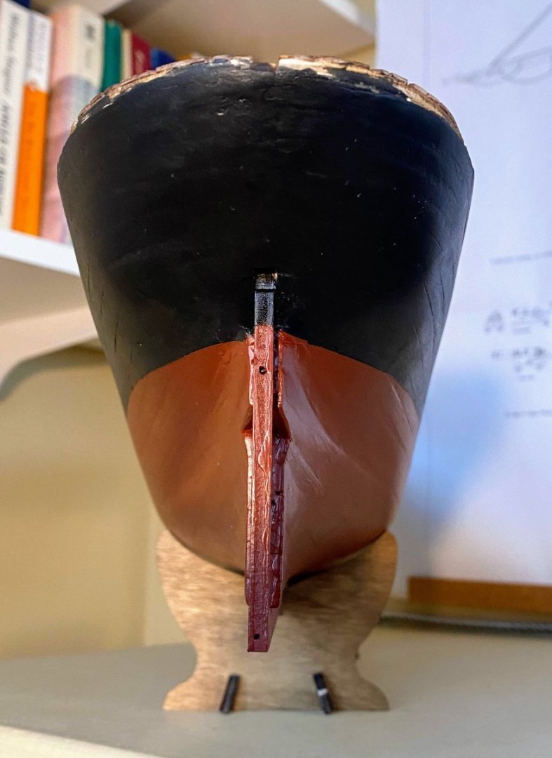
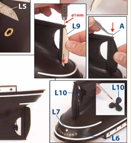
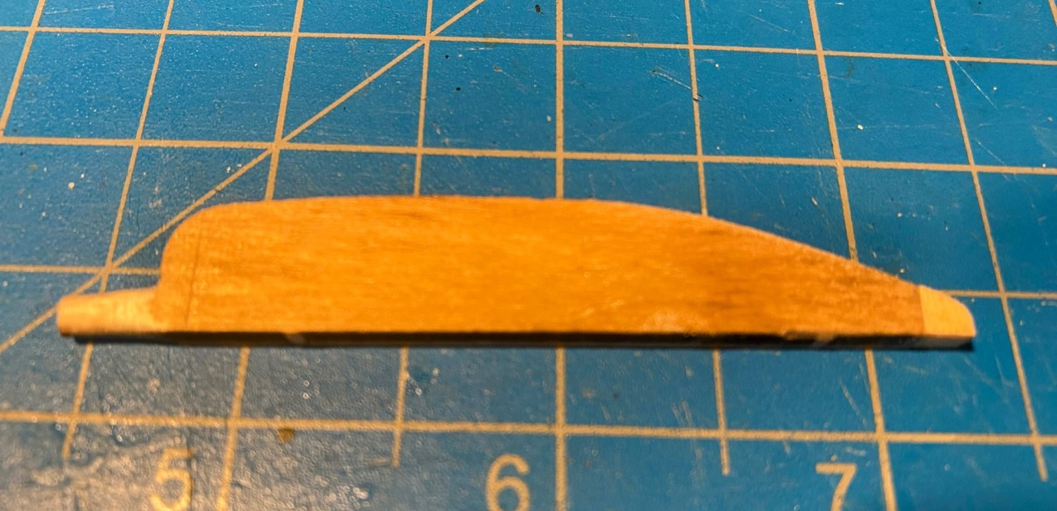
For the rudder, OcCre envisions an extension of the keel on which the bottom of the rudder rests, along with a shaft or pin extending from the extension up into the rudder and around which the rudder pivots. The plans I’ve posted previously (from the National Library of Scotland and the Ernest Shackleton website) show a more conventional pintle and gudgeon arrangement, and that is what I have chosen to model. I previously posted that I built my model with no such keel extension. What I noticed only upon zooming in on the plans, after my rudder was fully installed, is that there was also a very small keel extension (much smaller than OcCre's) that may have had a pin in it. I might be able to add that after the fact, so to speak, but I'm not at all sure it would be worth the effort. The kit’s rudder is laser cut, to which I needed to add a small block of wood so the rudder would be long enough to reach the bottom of the keel. To simulate pintles and gudgeons, I cut and bent pieces from a 1/16” (I think) strip of brass. I cheated a bit and made no effort to model pintle pins inserted into the gudgeons. To make this arrangement a little less fragile, I ran a tiny pin through the bottom pintle and the rudder post. Fortunately it isn't visible. One thing I find interesting is that it is clear from some Frank Hurley photos that the real rudder was simply a thick slab, with no hydrodynamic-friendly shape or taper like you would find on a more modern rudder. Were they just not concerned about that kind of thing a century ago?

- 206 replies
-
- 4
-
-
- Endurance
- Shackleton
- (and 2 more)
-
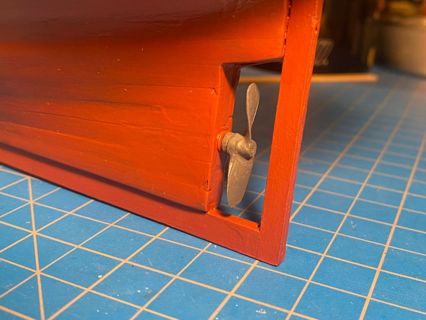
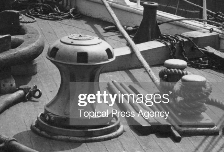
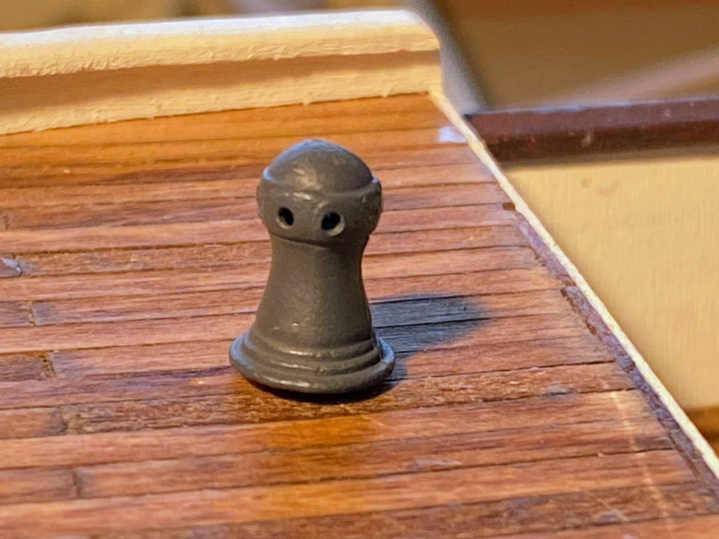
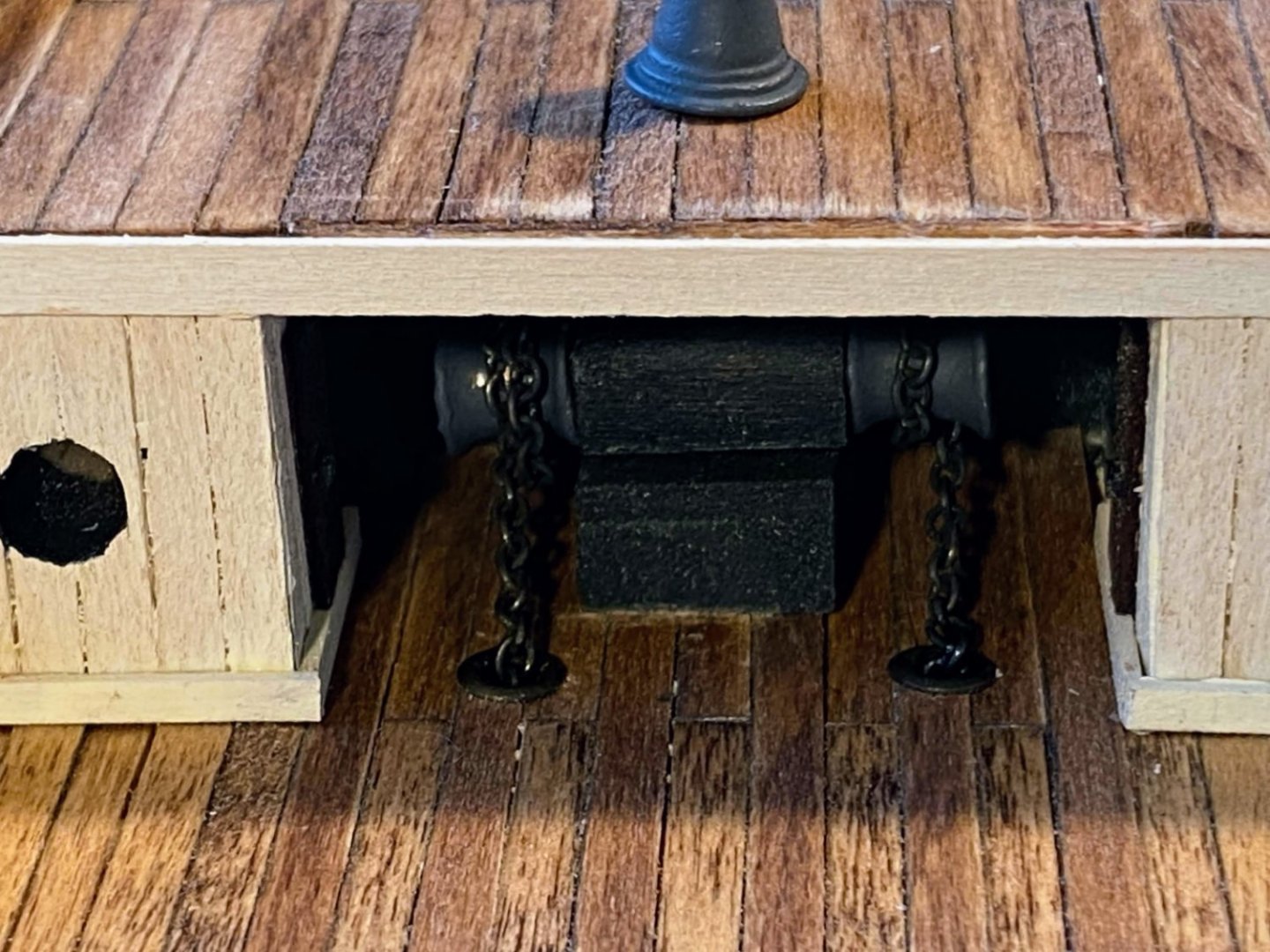
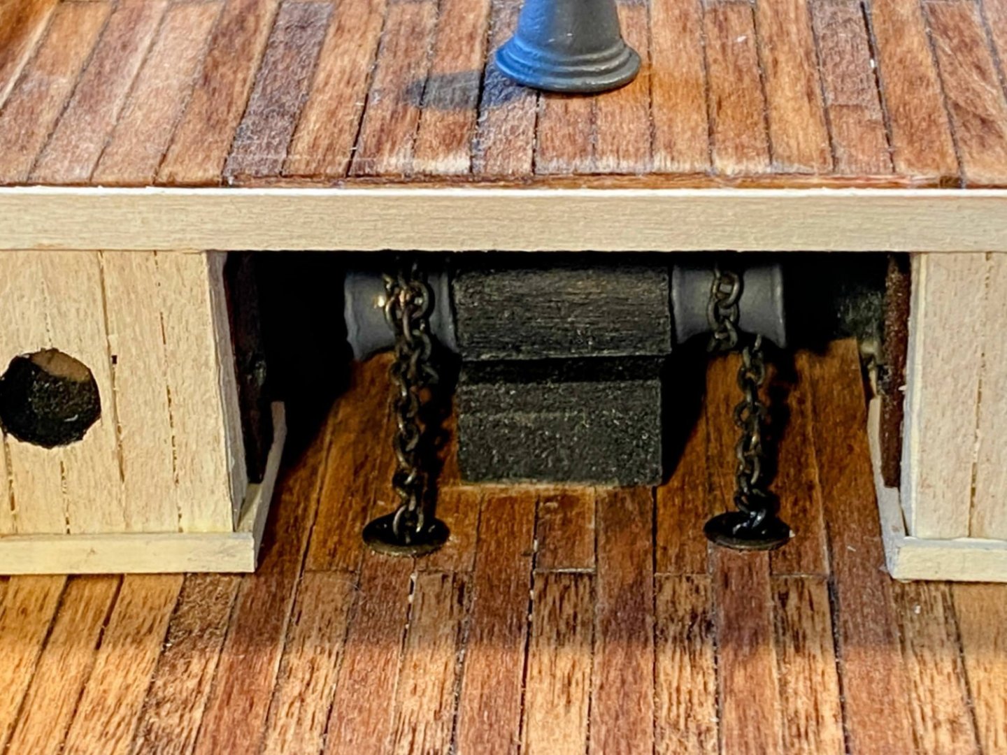
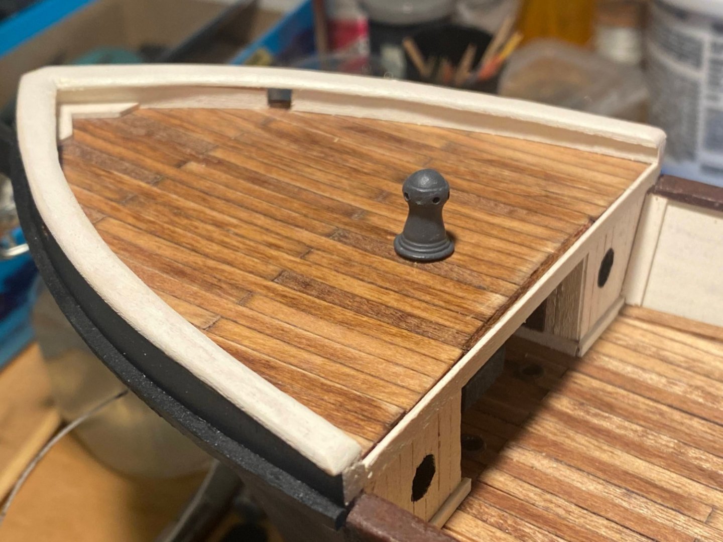
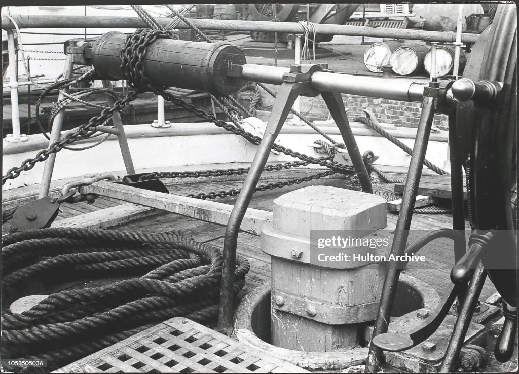
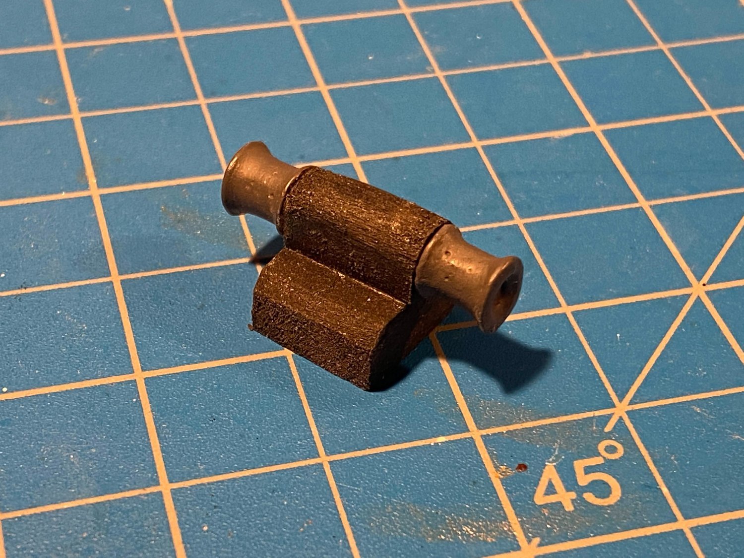
Quite some time ago I ordered a few fittings from BlueJacket, and more recently I did some things with them. First is a two blade propeller like the original ship, and unlike the three bladed one provided by OcCre. I added some length to the shaft with a very short piece of brass tubing, so that the prop is in the middle (fore and aft) of the space provided for it rather than right up against the back of the hull. Second I installed a more genuine looking capstan than the oft-criticized wooden one provided by OcCre. Capstans typically have removable bars that crew members bend over and push as they walk around the thing. Photos indicate that Endurance’s capstan had holes for such bars, but I haven’t seen any photos showing the bars stowed nearby as they typically would on a ship with a capstan. My conjecture is that the capstan was steam powered (ditto re the windlass) and that the bars would be used in an emergency but not stored conveniently nearby. And now (drum roll please) . . . exhaustively researched and exquisitely detailed (😀), this is the windlass no one will ever see. I bought two windlass drums from BlueJacket and glued them to a block of wood that bears little resemblance to a real windlass. I had previously blackened some of the kit-supplied chain with Casey Brass Black. Using the thread that’s been hanging out of the hull’s hawse pipes for months now, I carefully pulled the chain through the anchor hawse pipes and holes in the forward bulkhead, wrapped it around the drums, and fed it down the chain holes installed in the deck many months ago. I had finally fully consumed the bottle of Blacken-It I bought at least 20 years ago, and learned that that product is no longer manufactured. With help from these boards, I discovered the Casey product, and it worked just fine. The first photo below was taken with my iPhone without any after-the-shot touch up. It best resembles what can be seen with the naked eye. With the second one I used one of Google Photos' enhancement features. Looking at the latter photo I realized that I got the thing a bit off center when gluing it in place. Fortunately no one looking at the model from a normal viewing distance will ever notice. Close up pictures can be pretty annoying sometimes. 😀

- 206 replies
-
- 5
-
-
- Endurance
- Shackleton
- (and 2 more)
-
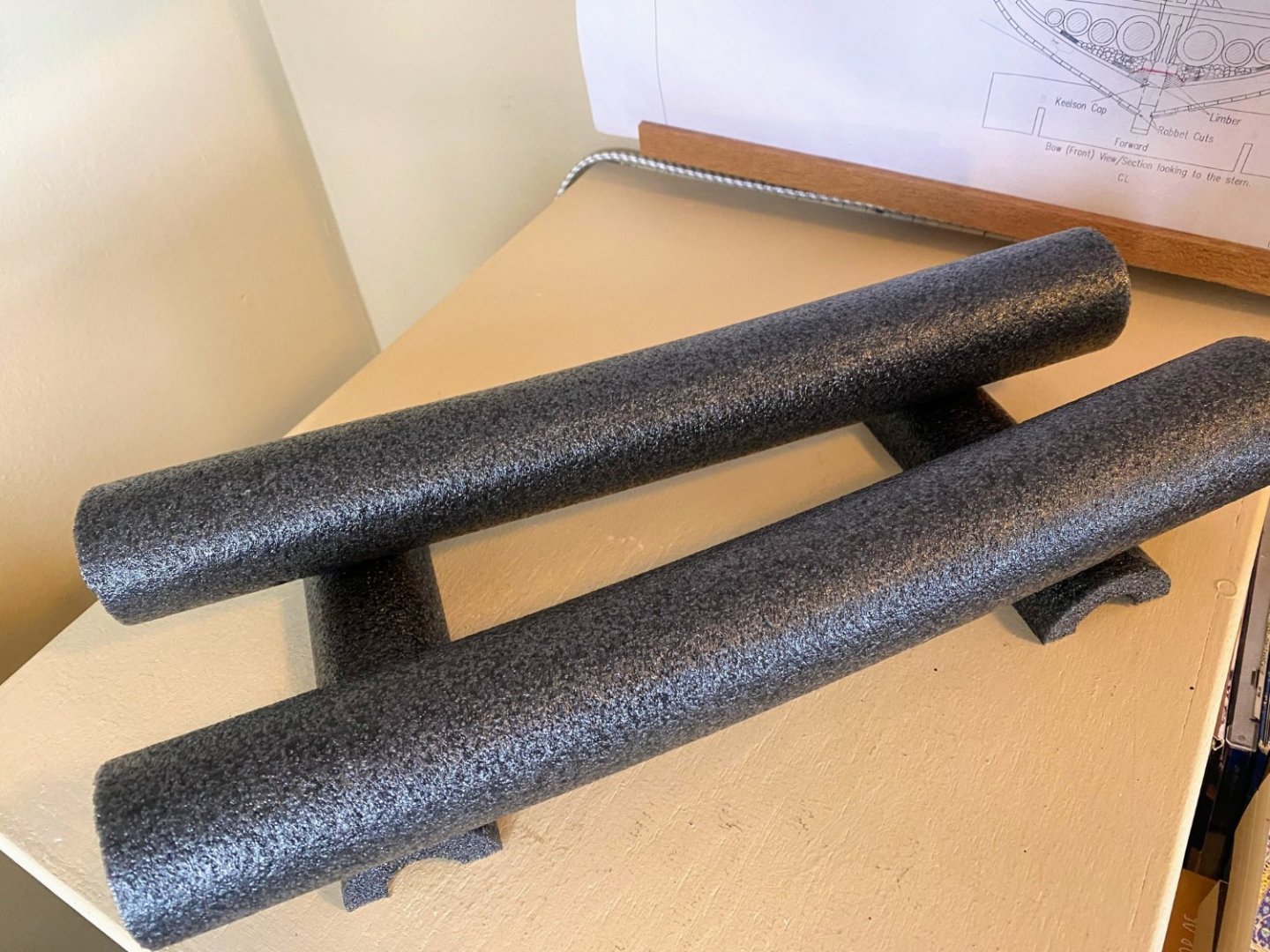
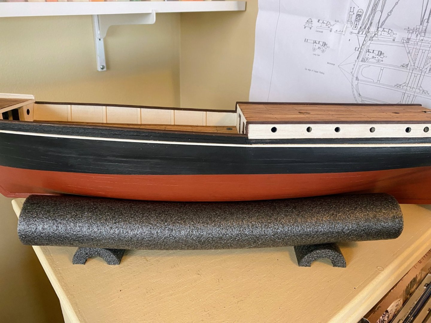
A few weeks back I was perusing these boards thinking about possible future builds when I came across this beautiful build of OcCre’s Beagle by The Gimps Chimp. Chimp put together a very simple but highly useful build cradle using pipe insulation (see post #101 of his build log). I bought a 6 foot length of 1” insulation at Ace Hardware for less than $3, easily cut the lengths I wanted, and built my own cradle. I tried gluing the pieces together with both CVA and CA glues and nothing worked very well. In an exchange of private messages with Chimp, he suggested a hot glue gun. I bought a cheap one of those in the school supplies section of Target, and it worked like a charm. As does the build cradle.
- 206 replies
-
- 5
-
-

-
- Endurance
- Shackleton
- (and 2 more)
-
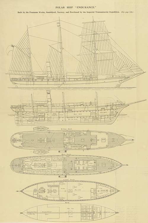
Good question Bobcat. The question of whether much of anything on this model is “authentic” is an elusive one, both because there is so little of the Endurance story that is about the ship (as opposed to the amazing endurance and rescue of the crew) and because substantial modifications were made between the time the ship left England and when it was crushed in the ice. There are quite a few photographs out there that show rigging, but not in a way that you can tell much about how the ship was rigged. I haven’t checked, but my guess is that the standing rigging is probably (or at least should be) pretty authentic, because it is clearly shown in the plans I copied from the National Library of Scotland’s website (see post #10 above). I have less confidence in the running rigging, in part because my research has disclosed virtually nothing about it and in part because the way some things are rigged by OcCre just doesn’t ring true for me. I’m no expert, but I have been aboard quite a few museum ships and as a young adult I spent many years sailing and racing smaller (up to 35’) sail boats. While I’m sure my build is not as far along as yours is, I have looked ahead a bit at the rigging plans and I find the following a bit troubling: As others have noted, much of the running rigging ends at eyebolts in the deck surrounding the base of the masts. I don’t think I’ve ever seen the running end of a sheet or halyard tied to an eyebolt. As Josh found searching photos (see the last photo in post # 41 of his log) of the recently discovered real ship, at least one of the masts had a ring of belaying pins around it, which is very common on sailing vessels of this era and older. I plan to put belaying rings around each of the masts. In a couple of cases (JT43 & 66 on the model’s rigging plan), the sheets for the jibs are tied to chainplate/deadeye assemblies. I’ve never seen that done on a sailing vessel. Virtually all running rigging aft of amidships is secured to an eyebolt (in many cases, eyebolts to which blocks are attached). I haven’t yet determined what I am going to do there, but I assume I’ll figure out a way to secure all running rigging to a belaying pin or a cleat. The kit doesn’t supply any cleats, but I intend to buy some. Bottom line is I don't think there is much out there that is helpful, but while that may be a curse, it is also a bit of a blessing . . . you can do with the rigging pretty much what you think looks authentic, and no one will be in a position to criticize.
- 206 replies
-
- 3
-
-
- Endurance
- Shackleton
- (and 2 more)
-
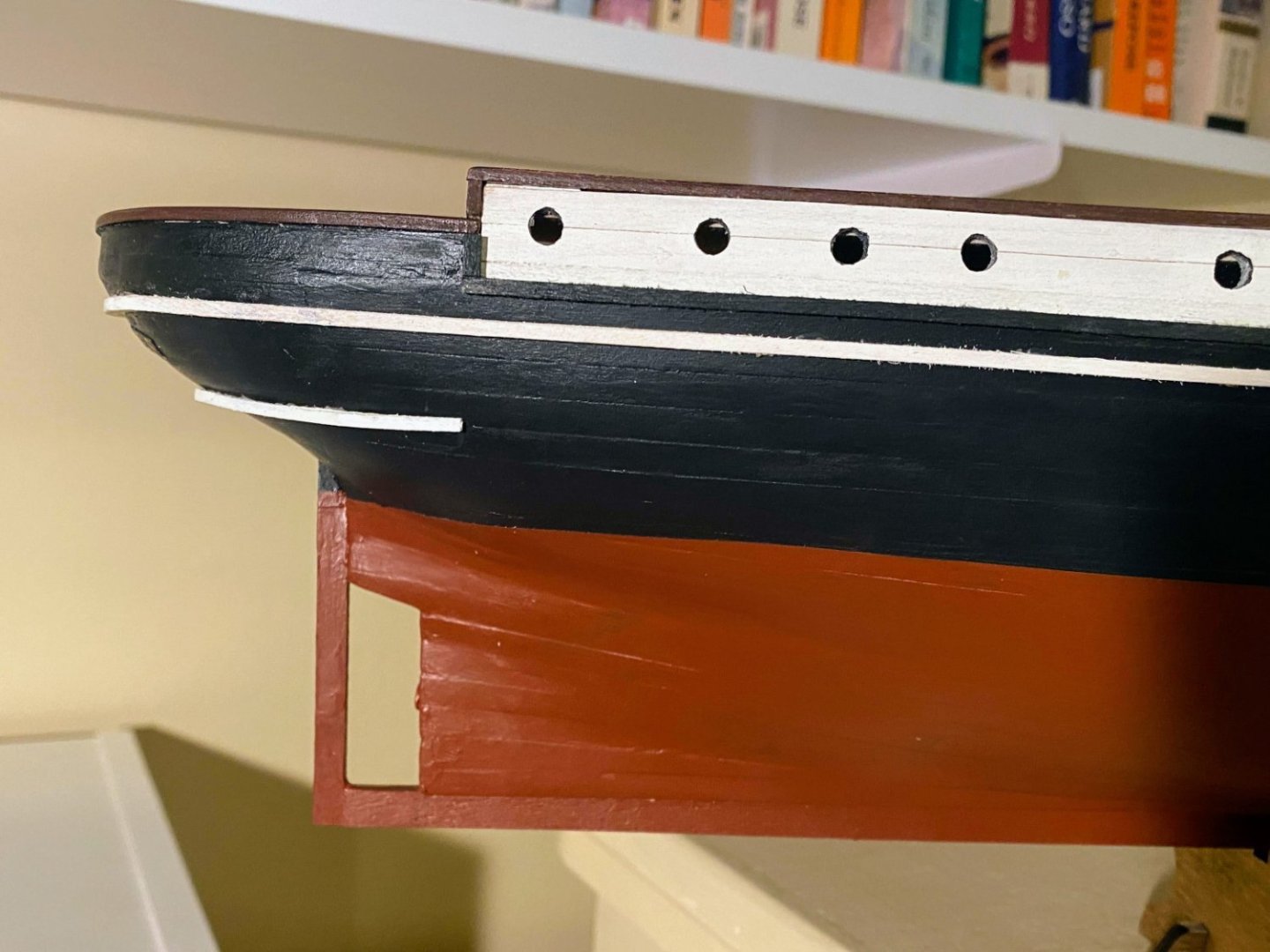
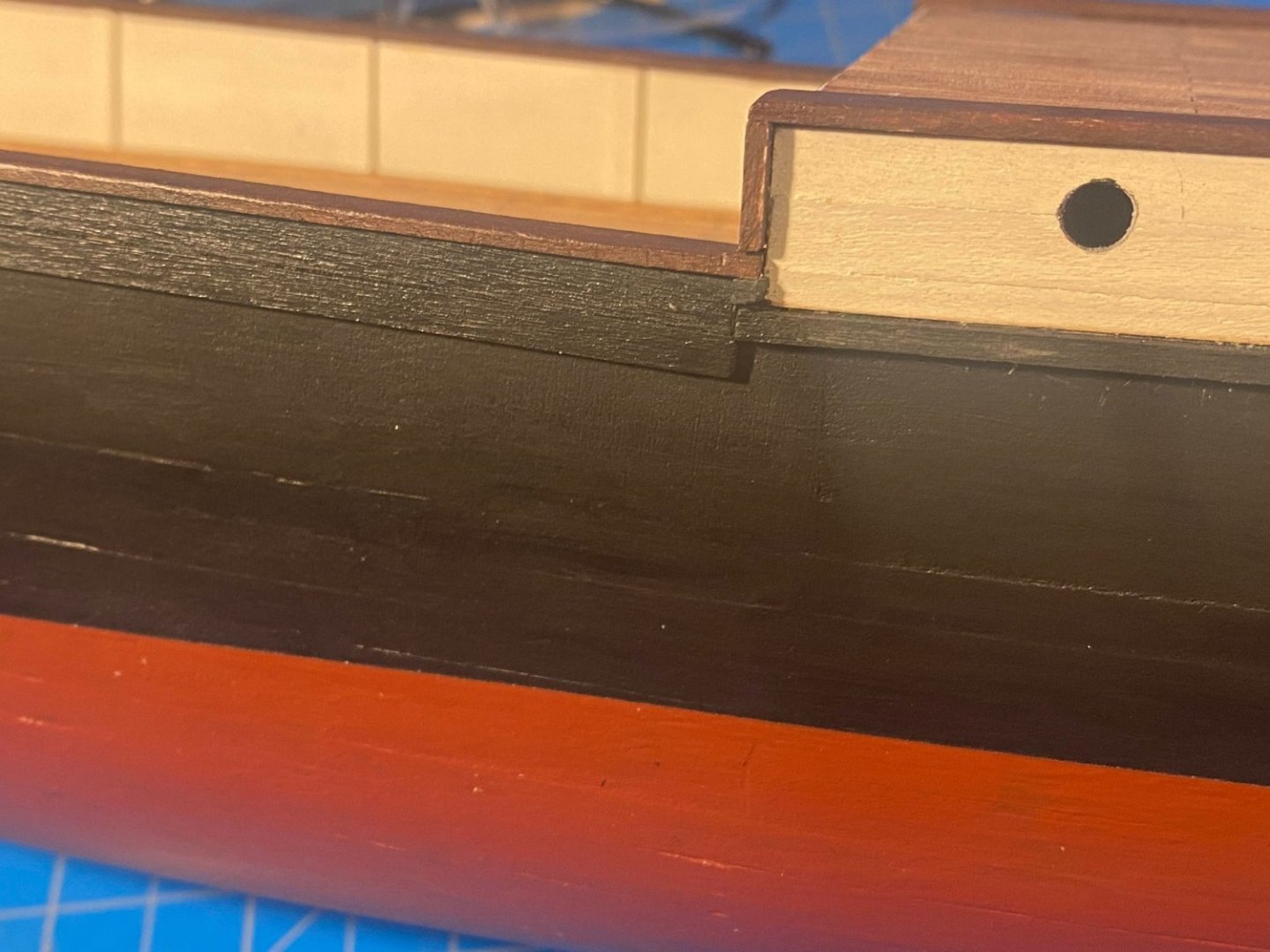
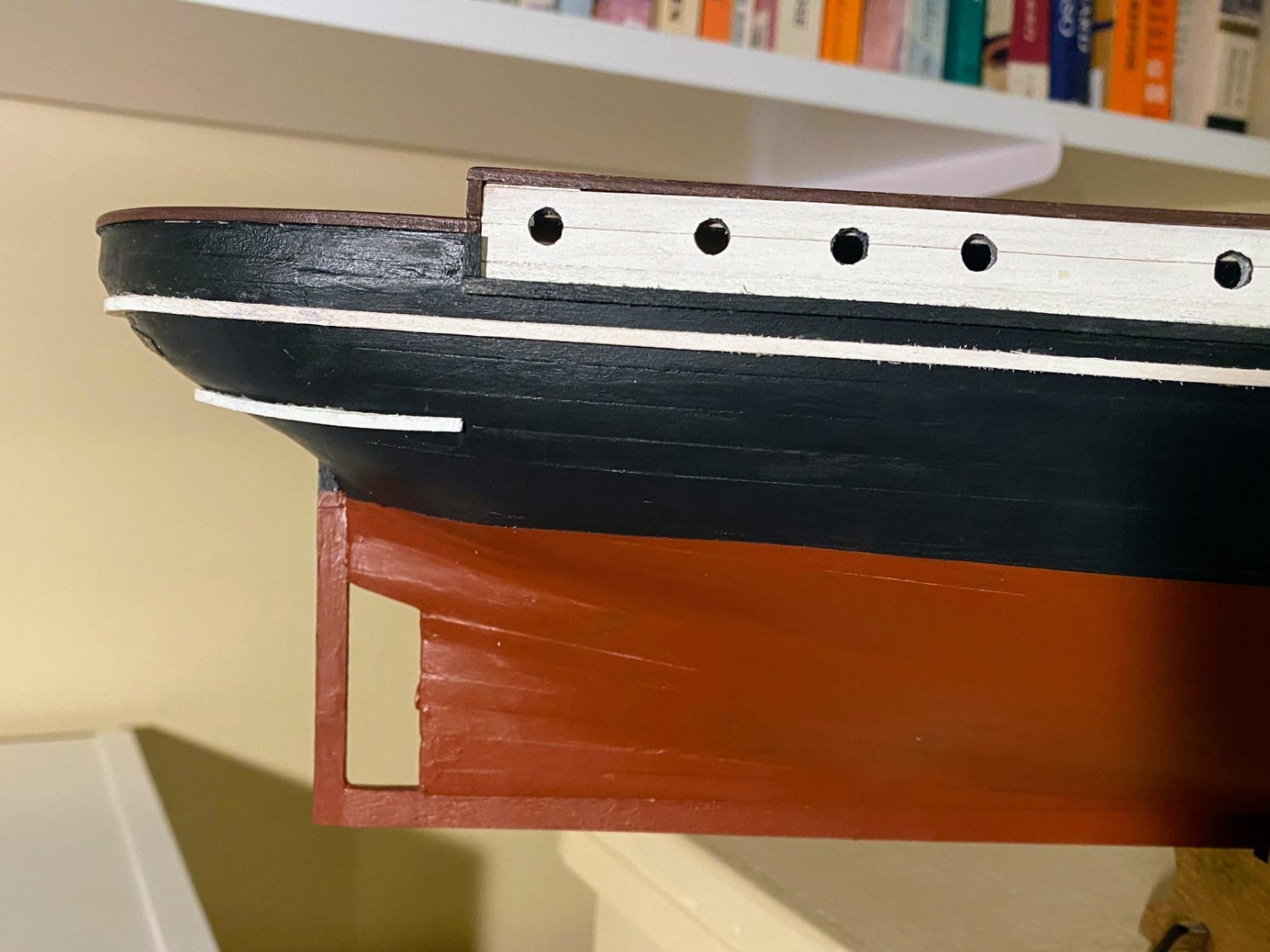
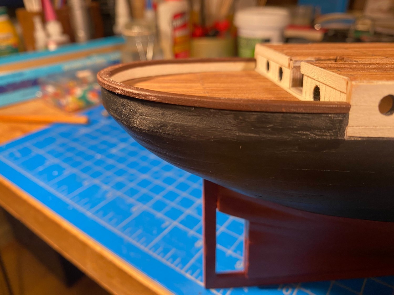
The lower white rub rail is considerably shorter than the upper one, but it presents its own challenge, due to the curvature of the hull. At the stern, it mostly hangs below the hull, glued to the hull on the upper surface of the 1/16 x 1/16” strip. But at its ends, a couple of inches forward, it is glued to the hull on the inside surfaces of the strip. Using my Dremel, I beveled the strip so that its upper, close to horizontal, surface in the middle becomes its inner, pretty much vertical, surface at the ends. Viewed close up, my limited Dremelling skills are pretty evident, but from a viewing distance it doesn’t look too bad. The upper rub rail’s glue residue seen in the first photo below has been cleaned up.
- 206 replies
-
- 5
-
-
- Endurance
- Shackleton
- (and 2 more)
-
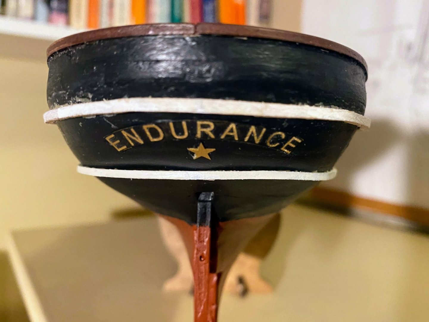
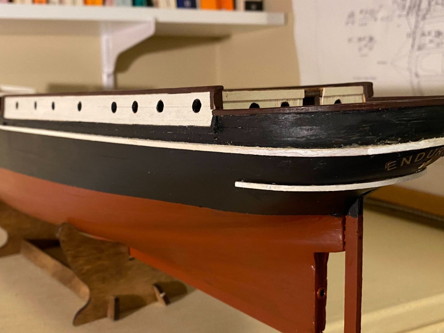
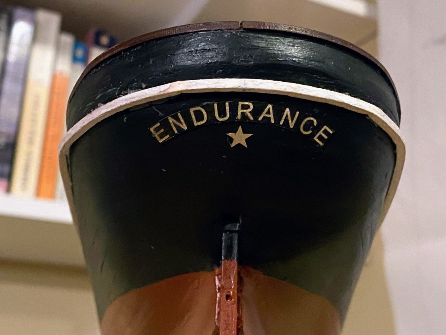
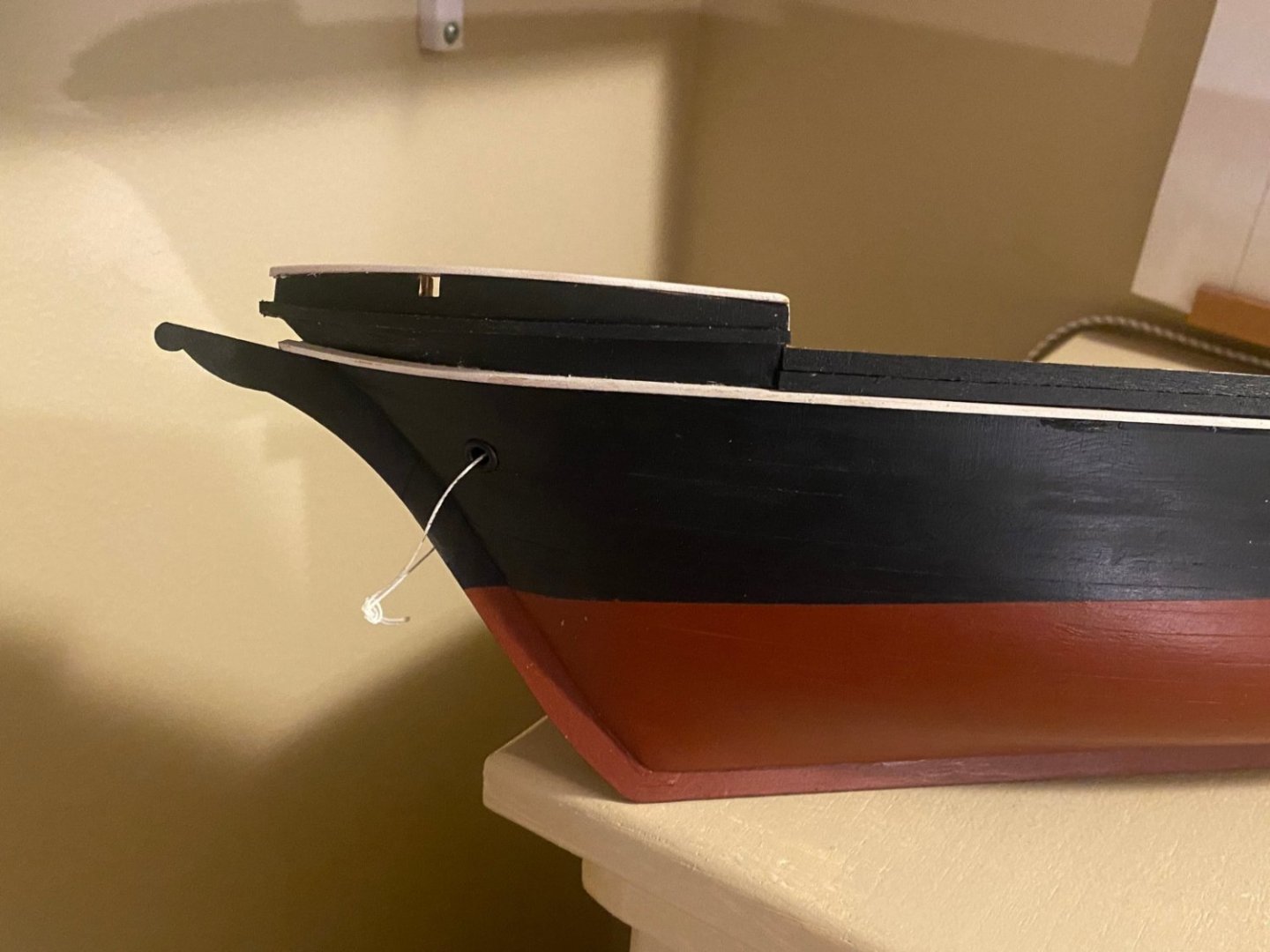
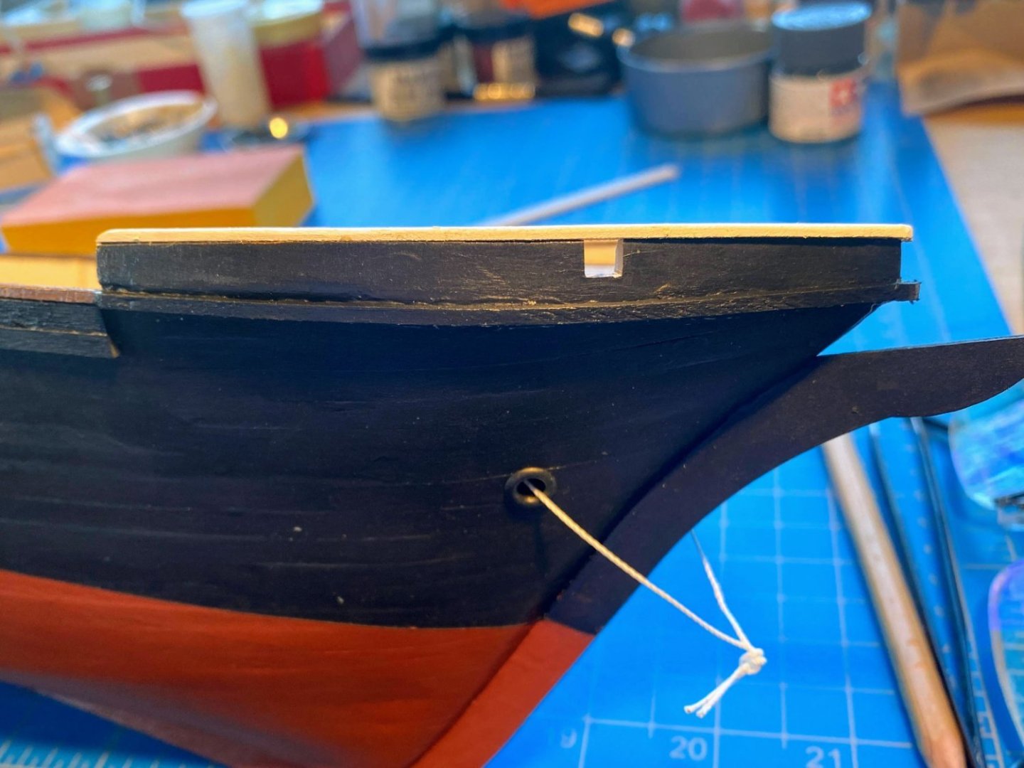
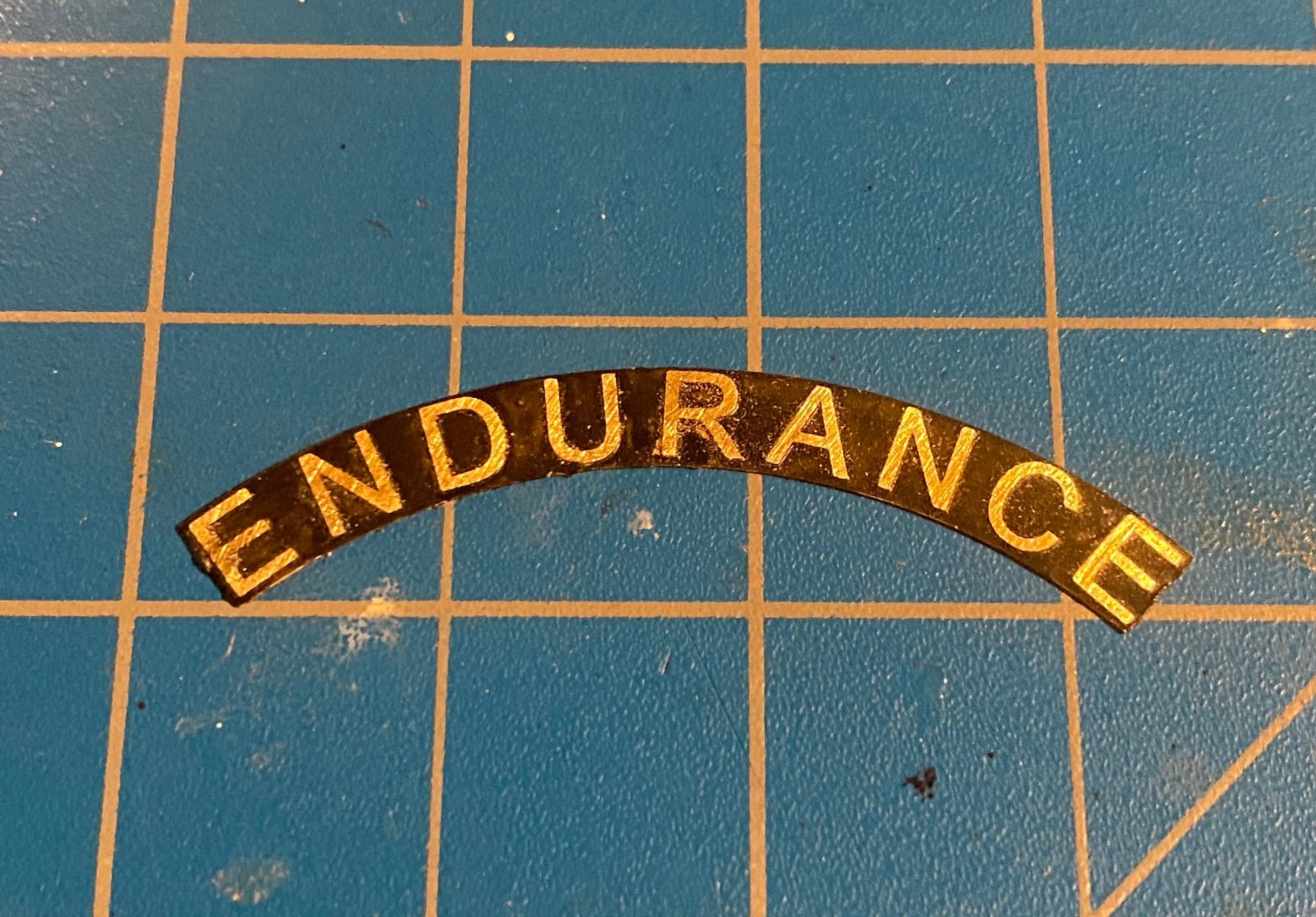
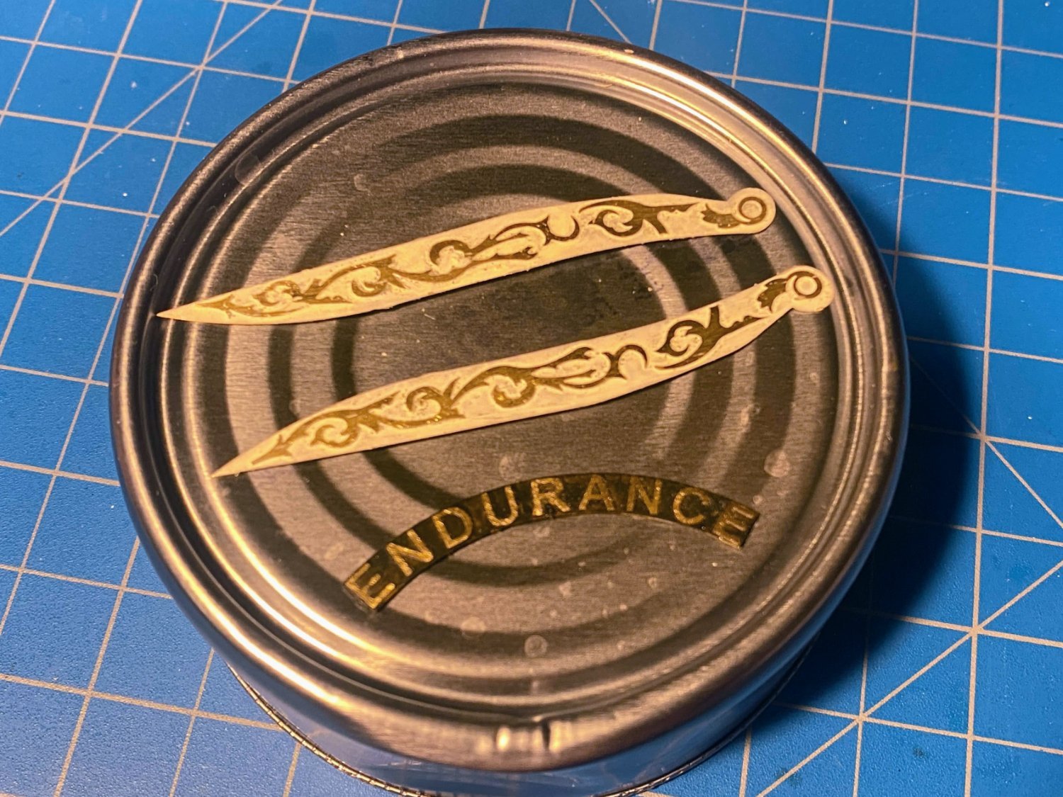
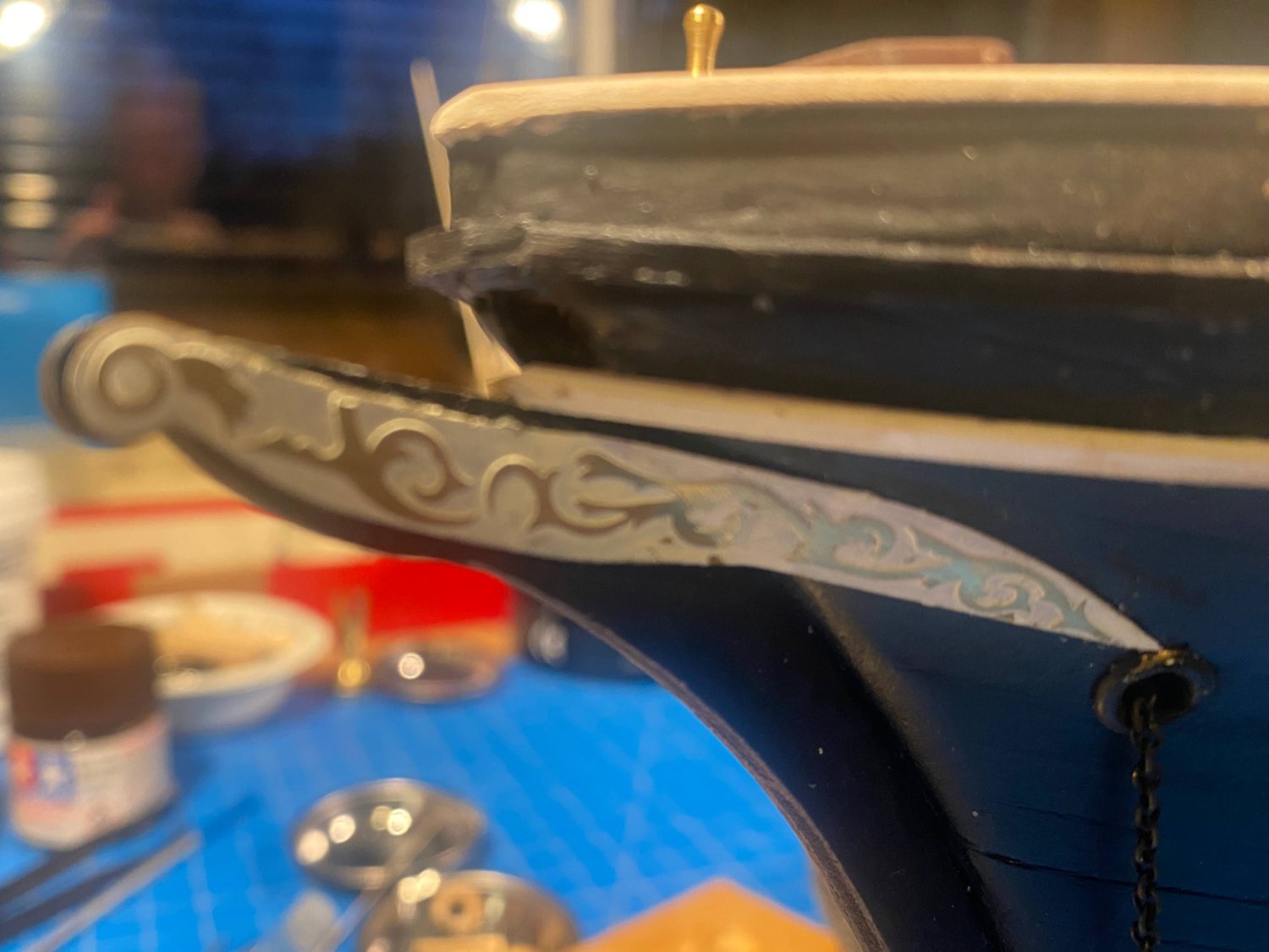
Thanks Kenny. I hope you enjoy your build as much as I'm enjoying mine. Next project was the Endurance name and star on the stern and the trail boards at the bow. These are photo-etched brass parts, painted black in the case of the name and white in the case of the trail boards, then sanded to remove the surface paint in the case of the raised letters and the raised trail board decorative elements. I was dubious as to how well this would work, but with little effort it worked flawlessly. Gluing the name and the star to the stern was not particularly difficult. OcCre has you paint the star white, but looking at one of the photos of the actual ship when it was discovered a couple of years ago, the star appears to be brass (or bronze) identical to the letters, so that is how I did it on my build. Gluing the trail boards to the bow was difficult, given the abrupt fold where the stem meets the hull. Minuscule differences in the location of that fold made a big difference in where the aft end of the trail board ended up on the hull. Unfortunately the aft end of the starboard trail board ended up noticeably below the aft end of the port one and below where I wanted it. I didn’t really notice until I looked at the two bow on. That is not how the model will usually be viewed when completed, but still I’m inclined to try to remove the starboard one and do a better job of placing it when I glue it back on. I didn’t get a picture of the discrepancy, and the photo I took of the port one didn't come out very well.


- 206 replies
-
- 5
-
-
- Endurance
- Shackleton
- (and 2 more)
-
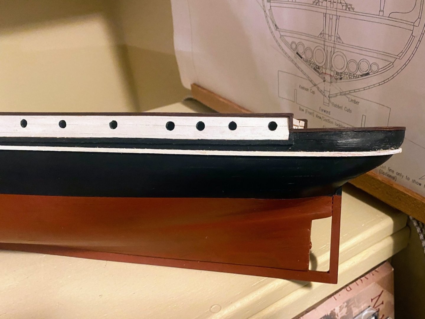
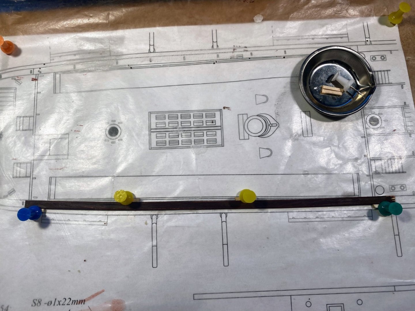
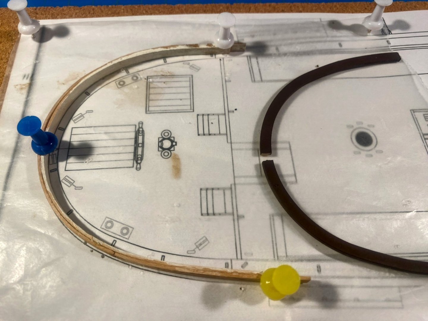
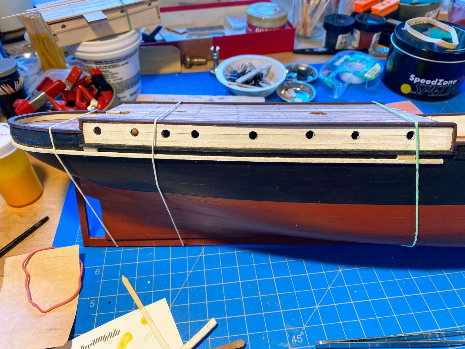
There are two rub rails painted white, one which runs around the full length of the hull and wraps around the stern, and a second one half an inch or so below that one that runs just around the stern. Anyone who has followed other Endurance blogs on these boards knows what I’m talking about. For the upper rub rail, the instructions have you cut a 150mm length (about 5”) of 2x2mm stock to bend around the stern (using whatever combination of heat and water you prefer). The kit includes several 2x2 by 600mm (almost 24”) strips to complete the rest of the rub rails. I decided to take a different approach and bend an entire 600mm strip, so that the necessary joint on each side of the hull between strips would be at a point where little bending occurs. I think this was a good approach, but it was a little hairy gluing 2 feet of 2mm square stock to the hull all at the same time. Before gluing it on though, it seemed to be more difficult than it should have been to get the stern section to bend the way I wanted it to. Last spring I mentioned that I found the hull planks unnecessarily difficult to bend, and I ended up planking most of the hull with 1/16” strips rather than the supplied 2mm strips, the former being a little thinner. Those strips proved easier to bend; however, the difference in thickness was so small I questioned whether that was what made the difference. Fast forward to this rub rail, and I wondered whether I should try 1/16” square stock I had on hand for the rest of the rub rail. I tried it and the bending process was much easier. It then occurred to me that I was probably using two different kinds of wood. In my experience, American kit manufacturers generally use basswood. I had read somewhere that some European manufacturers use lime wood, but I couldn’t find anything which told me what kind of wood OcCre uses in its kits. According to some posts I found on these boards, lime wood is considered to be superior, since it is a harder wood, with less “fuzz” than basswood. In any event, I found the basswood to be easier to use, and I will use it exclusively when I get to the lower white rub rail. If you look closely enough, there is a noticeable difference in thickness where the aft and forward parts of the rails join, but it’s very difficult to see from anything like a normal viewing distance. Backing up a bit . . . the instructions are supplemented by a couple of dozen or so YouTube videos, which haven’t been particularly helpful to me and which I have not referred to very often. But I did take a look at the video which shows the installation of this rub rail. The video, which has no narration, shows sticking a couple of narrow strips of wood of appropriate width to the hull with some sort of putty (bubble gum?😀) to assist in positioning the rail for its entire width. When rigging a model I like to use diluted white school glue to secure knots, and I gave that a try with these little strips of wood. I was very cautious not to use too much of this diluted glue, so much so that at first they popped off the hull at the slightest provocation. Using a little more glue worked perfectly; they stayed in place as I was positioning the rub rail, and when I wanted to get rid of them, I was able to pry them off without leaving behind any trace of having been there. This may be my last post before I get evicted from the shipyard, the shipyard becoming a guest room for the holidays. We have the great fortune to have both kids home for Christmas, our daughter and her husband and our son and his long time girlfriend. Happy holidays everyone.🎄🎅🎄

- 206 replies
-
- 6
-
-
- Endurance
- Shackleton
- (and 2 more)
-
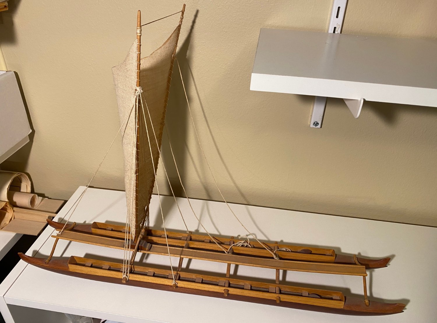
Glen, I just stumbled upon your build, and it is truly amazing. It also brings back some wonderful memories. My parents spent their last few decades living in Hawaii, and as a young adult I lived there 18 of those years. At some point, my dad, a life-long sailor and a great admirer of the Polynesian voyagers, bought the completed model pictured below. I think he found it in Hawaii, but it might have been in French Polynesia. In any event, I was lucky enough to inherit it, and it now sits right beside my work bench. My years in Hawaii included the initial voyages of Hokulea, the first modern replica of these amazing vessels. One of the greatest thrills of my many sailing adventures was sailing several miles offshore on my Hobie 16 (along with maybe another hundred other boats) to greet Hokulea on her return to Kaneohe Bay, at the end of her initial voyage to French Polynesia and the island of Tahiti. That was in the mid-70s, and I still remember it almost like it was yesterday. Again, congratulations on a great build.

- 174 replies
-
- 10
-
-
- Waa Kaulua
- bottle
- (and 1 more)
-
There are rub rails on either side of the bow, running the length of the forward deck a little bit below deck level, made from 2x2 mm stock. The instructions have you install them before painting the hull, which isn’t a bad idea. I don’t always follow instructions. I found bending these strips to fit the sides of the hull to be challenging, since they not only bend in and out, and up and down, but they also twist a bit. The starboard one popped off twice after gluing, needing to glue it to the hull a third time before it stuck. An aside here . . . I use TiteBound wood glue almost exclusively on my builds. The smallest bottle I’ve seen holds about 4 oz., and the bottle I was using still had about 1/3rd left. It occurred to me that maybe I should see if TiteBound has a shelf life, and sure enough, the website says you can determine how old it is and whether it needs replacing by entering a code number stamped on the bottle. The number was too smudged on my bottle to be readable, but I did see advice on a couple of websites that the glue should be replaced after about two years. I have no idea how long ago I bought the bottle I’d been using, but I have no doubt it was way more than two years ago. I bought a new bottle, and that is what I used on my third try on the starboard side, and the first and only try on the port side. Unfortunately I apparently wasn’t paying much attention to placement on the port one, because after the glue was very dry on that side, I compared the two, and the port side rub rail droops noticeably when compared to the starboard side. Maybe someday I will pry the port one off and reposition it, but I am reluctant to do so for fear I’ll cause a greater mess in the effort. At least things look good where I used a short piece of 2x2 mm and a lot of sanding to bring the two rails together at the stem.


- 206 replies
-
- 6
-
-
- Endurance
- Shackleton
- (and 2 more)
-
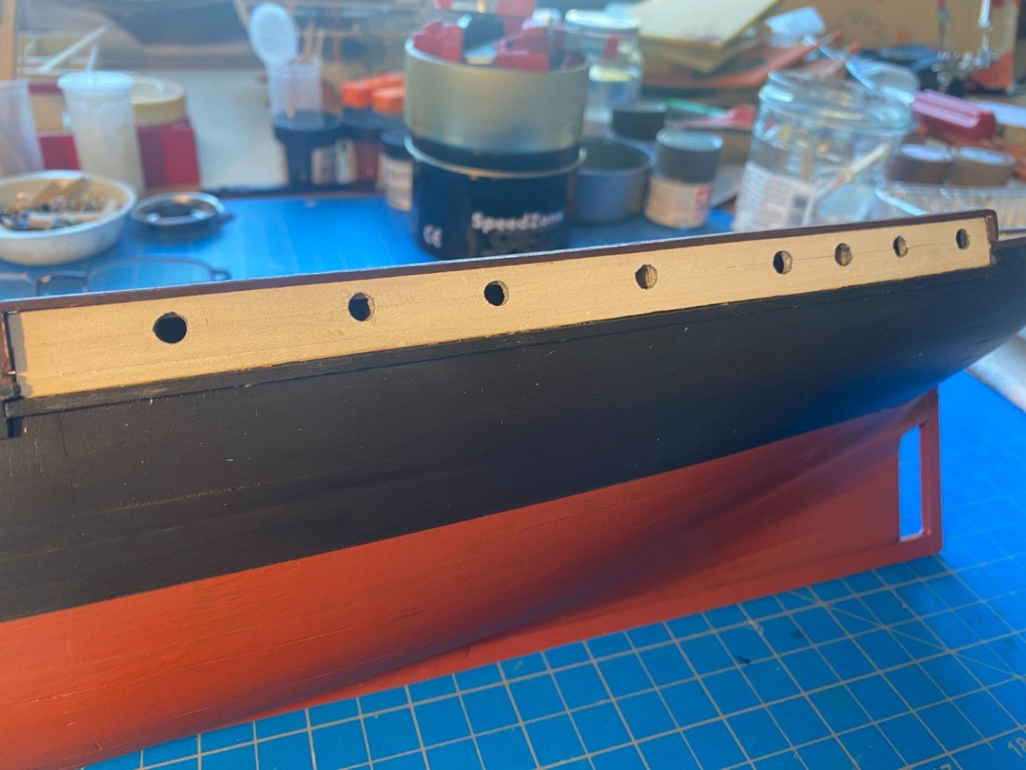
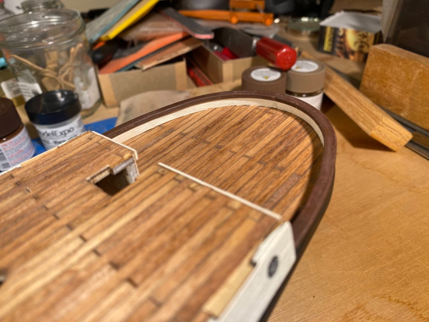
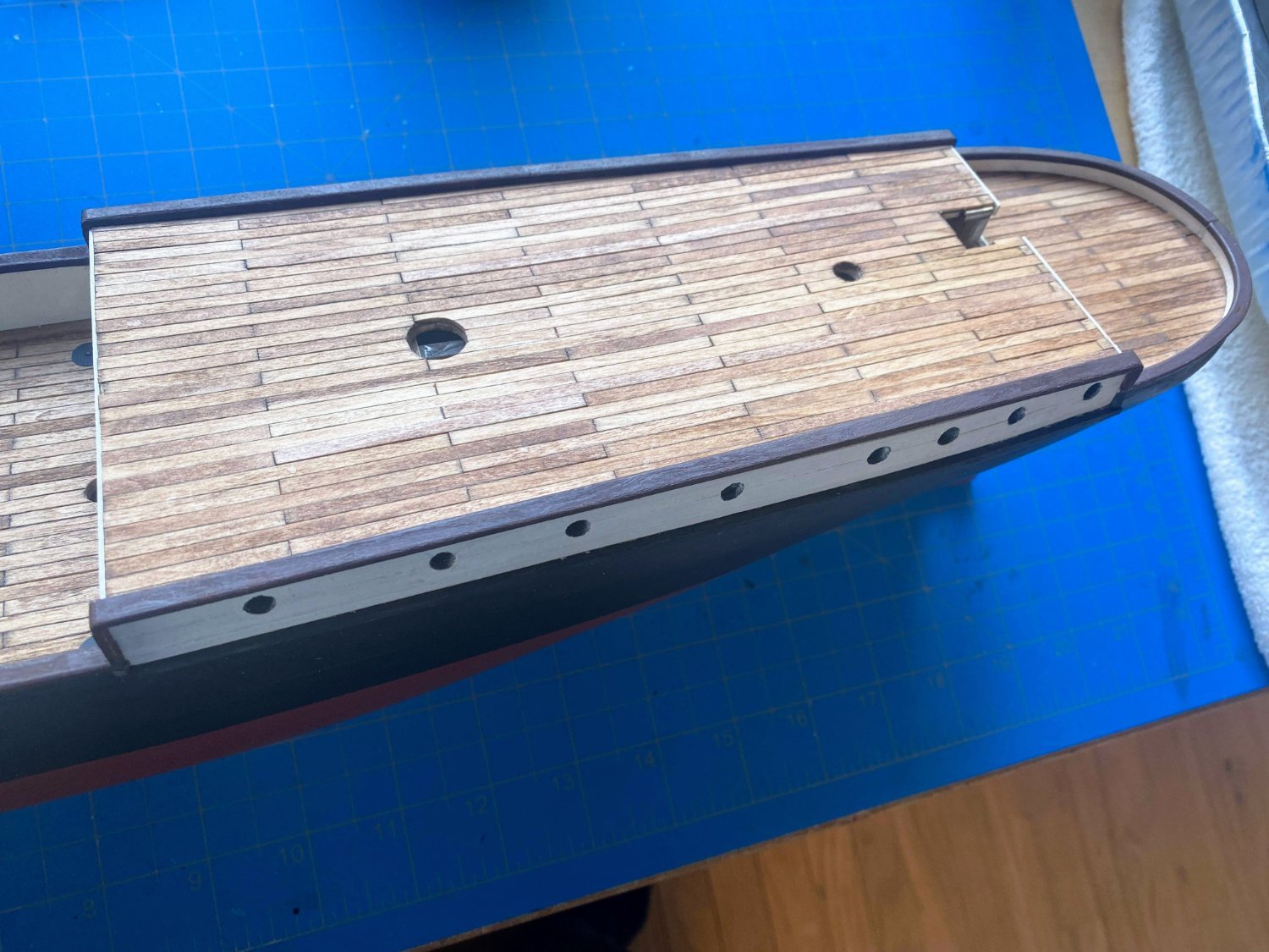
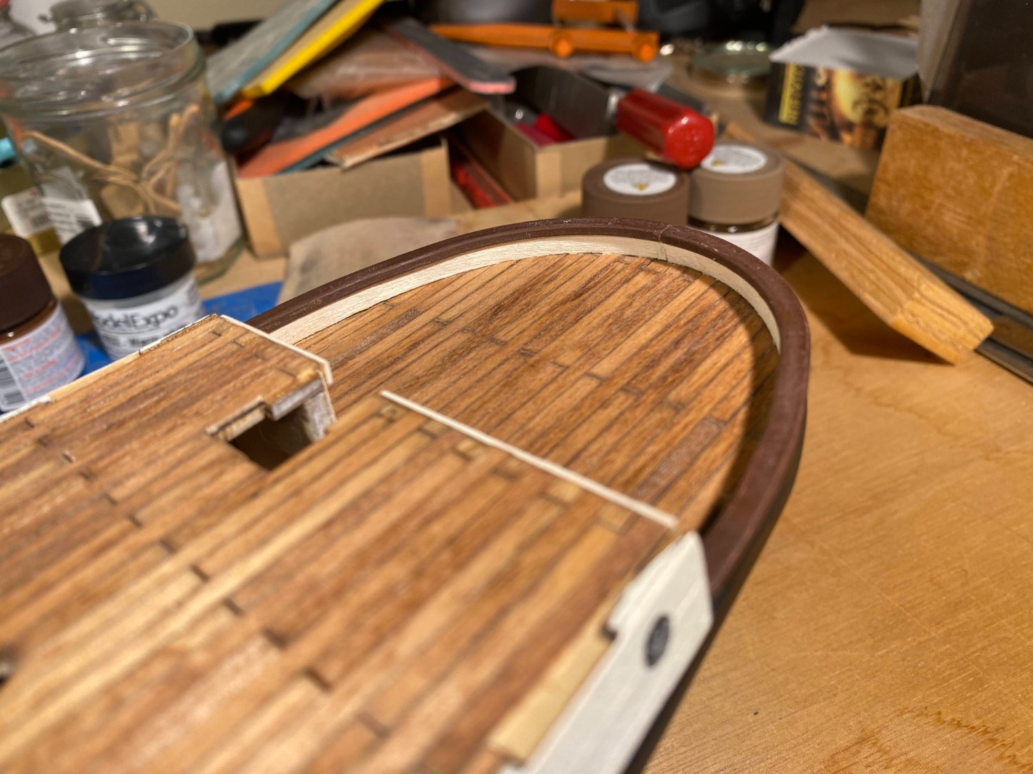
My progress on the build is moving well ahead of my progress on this blog. I have some catching up to do here. The caps on the bulwarks and the trim on the outer edges of the upper deck are made from 2x5 mm strips, painted brown. That seemed pretty straightforward, but proved to be a little more challenging than I expected, since all those pieces are slightly curved. I started with the bulwark pieces, forcing the curve by clamping them to the bulwarks. After everything had dried, I realized that I hadn’t lined up the caps to the bulwarks very well, and especially on the port side, it didn’t align very well at all. More recently, while apparently manhandling the hull without sufficient care, the port side cap popped off (after these pictures were taken). I have not glued it back on yet but I'm glad that's the one that didn't stick. I moved onto the upper deck trim, and this time used some water and heat to pre-bend the strips. Here of course there was no way to use clamps to force some bend when installing them on the ship, but pre-bending took care of the problem. The lower edge of the part of the hull with all the portholes is framed with a 2x2 mm black strip, basically a rub rail. The instruction’s photographs show this piece running in a continuous line with the lower deck bulwarks caps, but on my build that part of the hull runs a couple of millimeters below the bulwark caps. It took me a while to figure out the discrepancy, but here’s the reason. That part of the hull, with all the portholes in it, is a supplied laser cut piece. After gluing that piece in place, I planked it with veneer and painted it white. If you do as OcCre contemplates and plank the entire hull with veneer, the instructions show using a single strip running as described above, running continuously below the bulwarks cap and covering the lower few millimeters of what I painted white. I didn’t add a veneer layer to the hull as other builders did (see builds by HakeZou, Clearway and theoracle09; and hey Keith and Josh, where did you go?). When I framed the area with trim, what I framed was what I had painted white. Not a big deal; I’m perfectly happy with it as I did it. The instructions have you install a veneer strip (1x4 mm, painted black) immediately below and running the length of the lower deck bulwark caps. I'm not sure there was anything comparable on the real ship, but I installed it anyway figuring (as I am now confirming) it would help with installing the white rub rail. Because of the jog (exhaustively) described above, I used two 1x4 strips on each side instead of one. As an aside, I don't know a lot about photography, and all of the photos I've posted were taken with my iPhone. I first two pictures above showing a significant amount of deck reflect most accurately what I see when I look at my build. But many of the photos I've posted had a more orange tint to them, like the last two posted above. If the latter showed more deck, you'd see a stark difference. Obviously different lighting makes a difference, but I haven't figured what lighting gets me pictures more like the former ones. I have fooled around with Google Photos editing tools, but to no avail.


- 206 replies
-
- 6
-
-
- Endurance
- Shackleton
- (and 2 more)
-
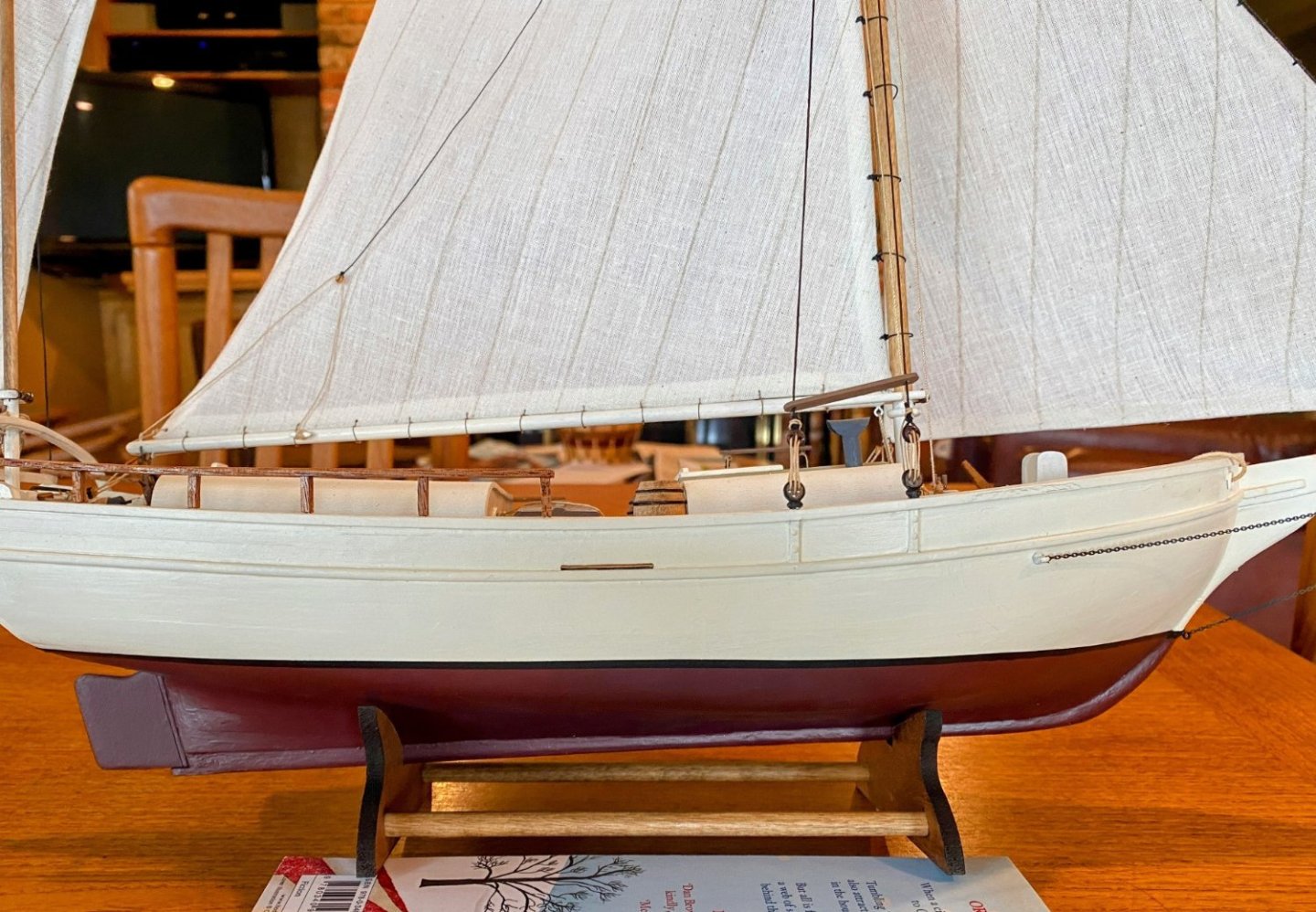
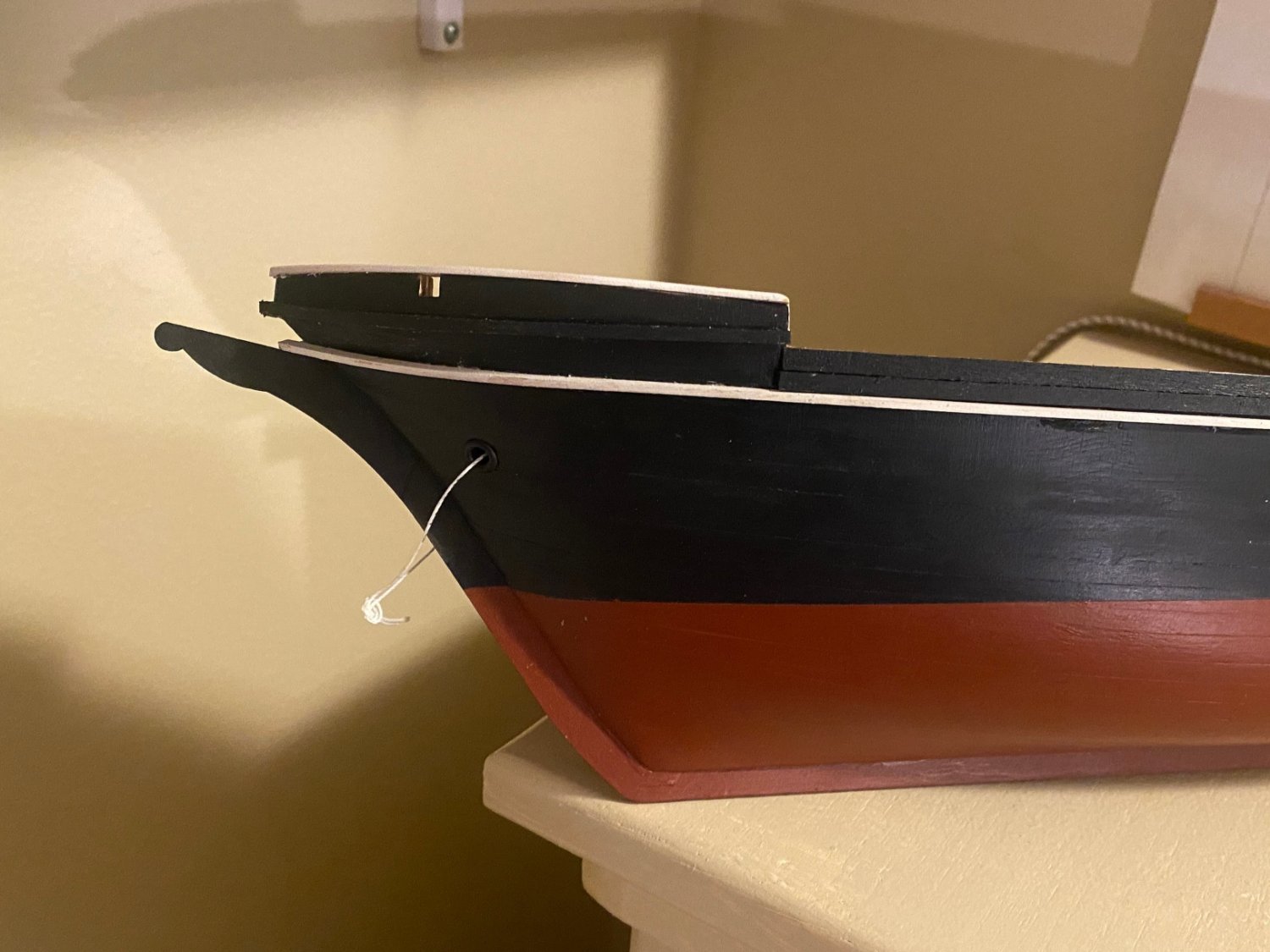
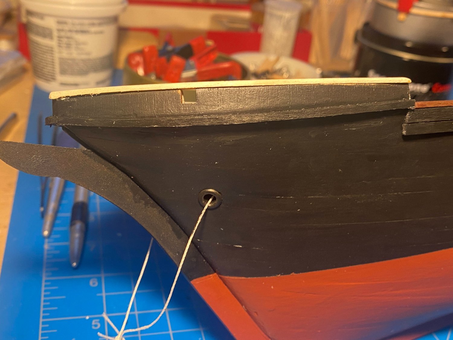
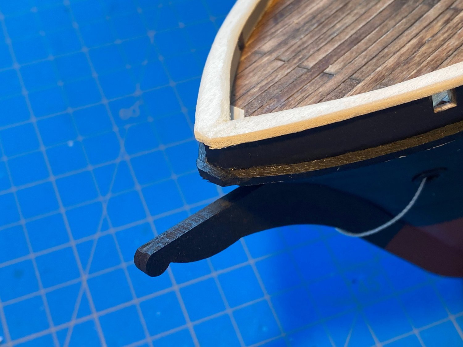
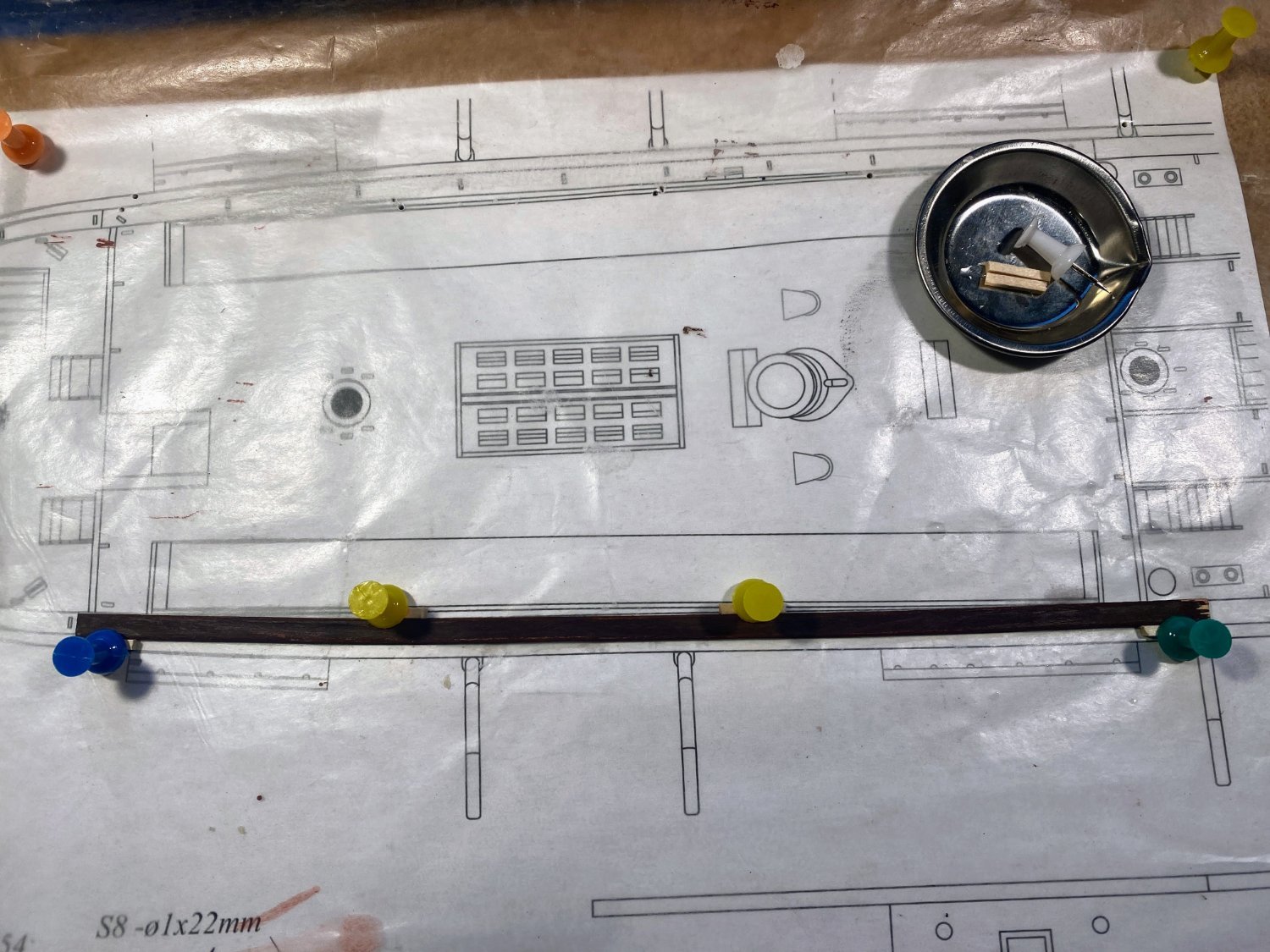
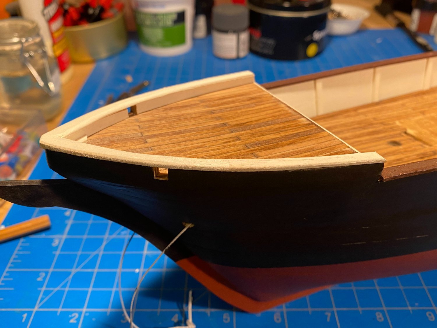
Happy Thanksgiving everyone. Moving on to trim pieces and rails . . . cap, hand, & rub. A couple of things not included in OcCre’s build of Endurance. . . First, there is a cap rail that tops the mini-bulwark that is at the bow, which can be seen in the photo of the ship below. OcCre could have provided laser-cut pieces for the same, as it did in the stern, but for some reason it didn’t. I pulled out my jeweler's jigsaw, cut out a pair of rails from a 1/16” sheet, and after a fair amount of sanding (I’m not very skilled on the jigsaw), came up with what you see in my photos below. Second, at the other end of the ship, as you can see in the photo below, there is another mini-bulwark that goes around the poop deck. This was a little more challenging. I tried to wet, heat, and bend a 2 mm thick strip to fit, and I just couldn’t make it work. Doing the same with laminated 1 mm strips worked a lot better. The result didn't fit on the deck all that cleanly, but some filler, sanding and paint made things look pretty good. OcCre’s provided laser-cut rail caps fit on top perfectly.


- 206 replies
-
- 7
-
-
- Endurance
- Shackleton
- (and 2 more)
-
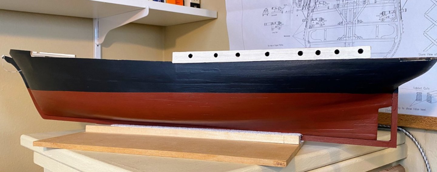
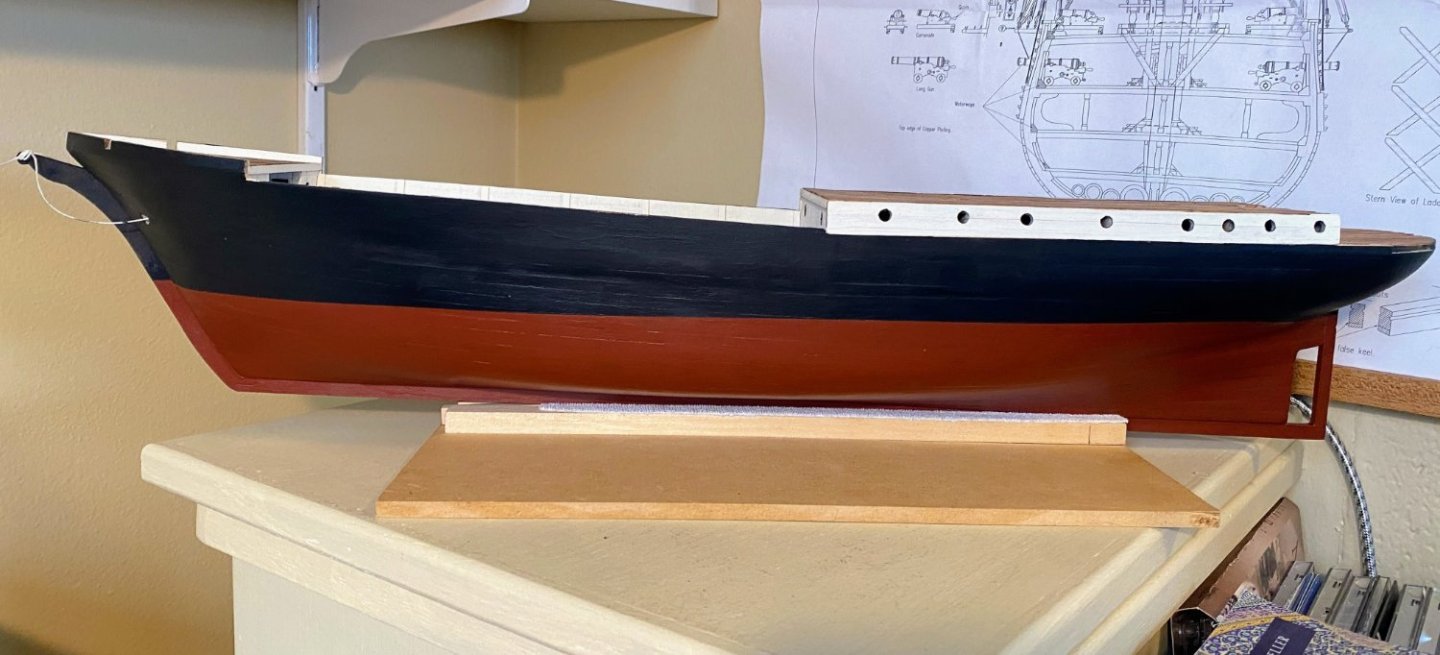
Thanks Bob. I've decided I like the dark red just fine. Looking through my photos, in some of them it appears brighter red than it really is, depending upon the lighting. After doing the starboard side, I took the following pictures. I'm not only pleased with the color, but somehow I managed to make the two sides pretty symmetrical. On close examination some minor deviation can be found, but none too obvious. Especially from what will be normal viewing angles.
- 206 replies
-
- 3
-
-
- Endurance
- Shackleton
- (and 2 more)
-
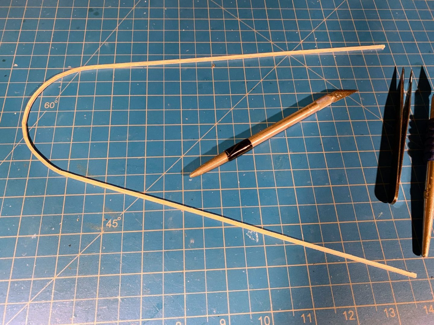
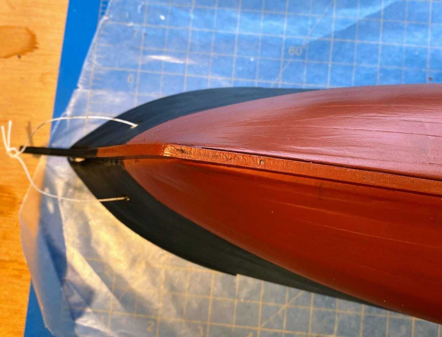
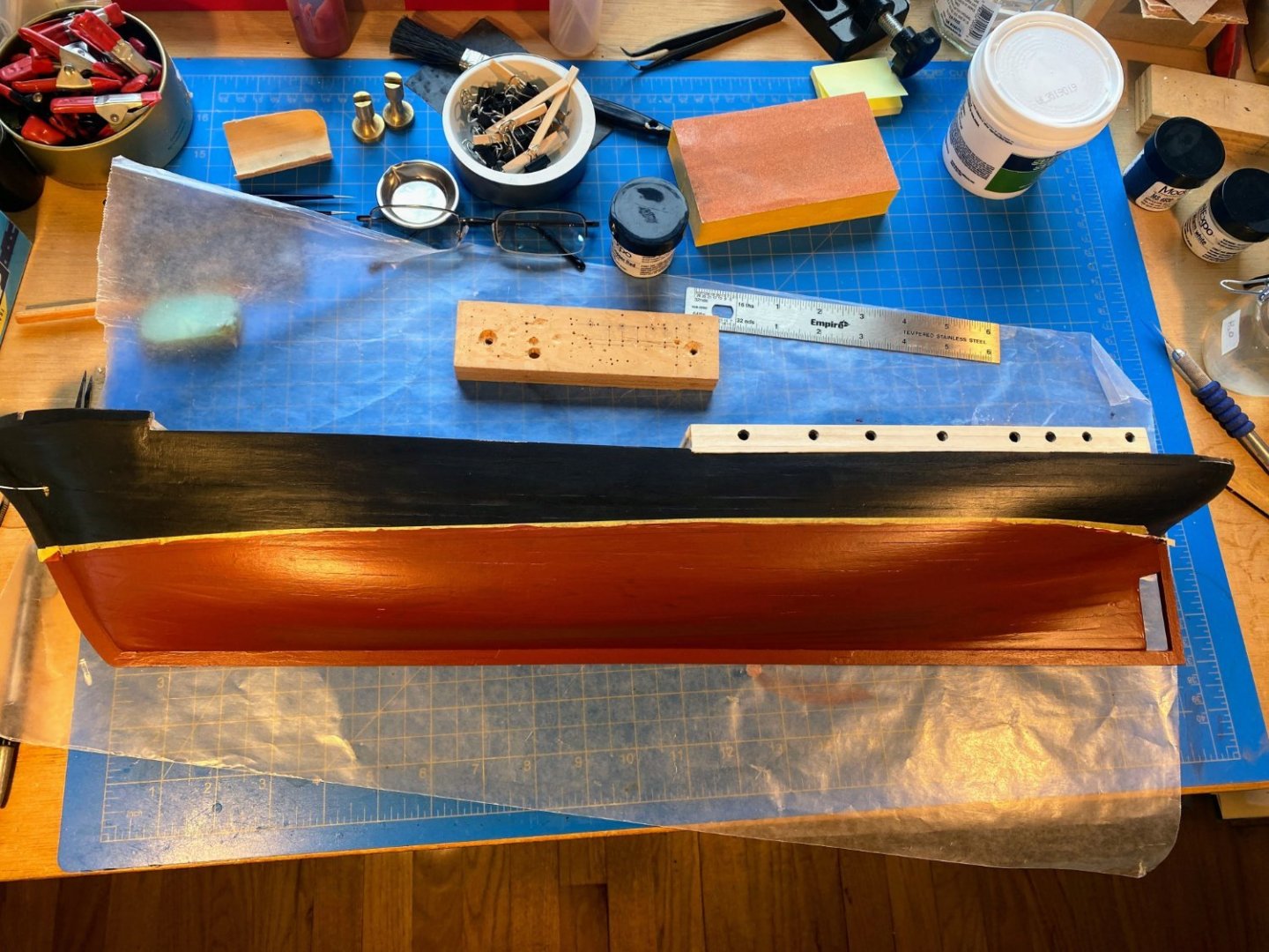
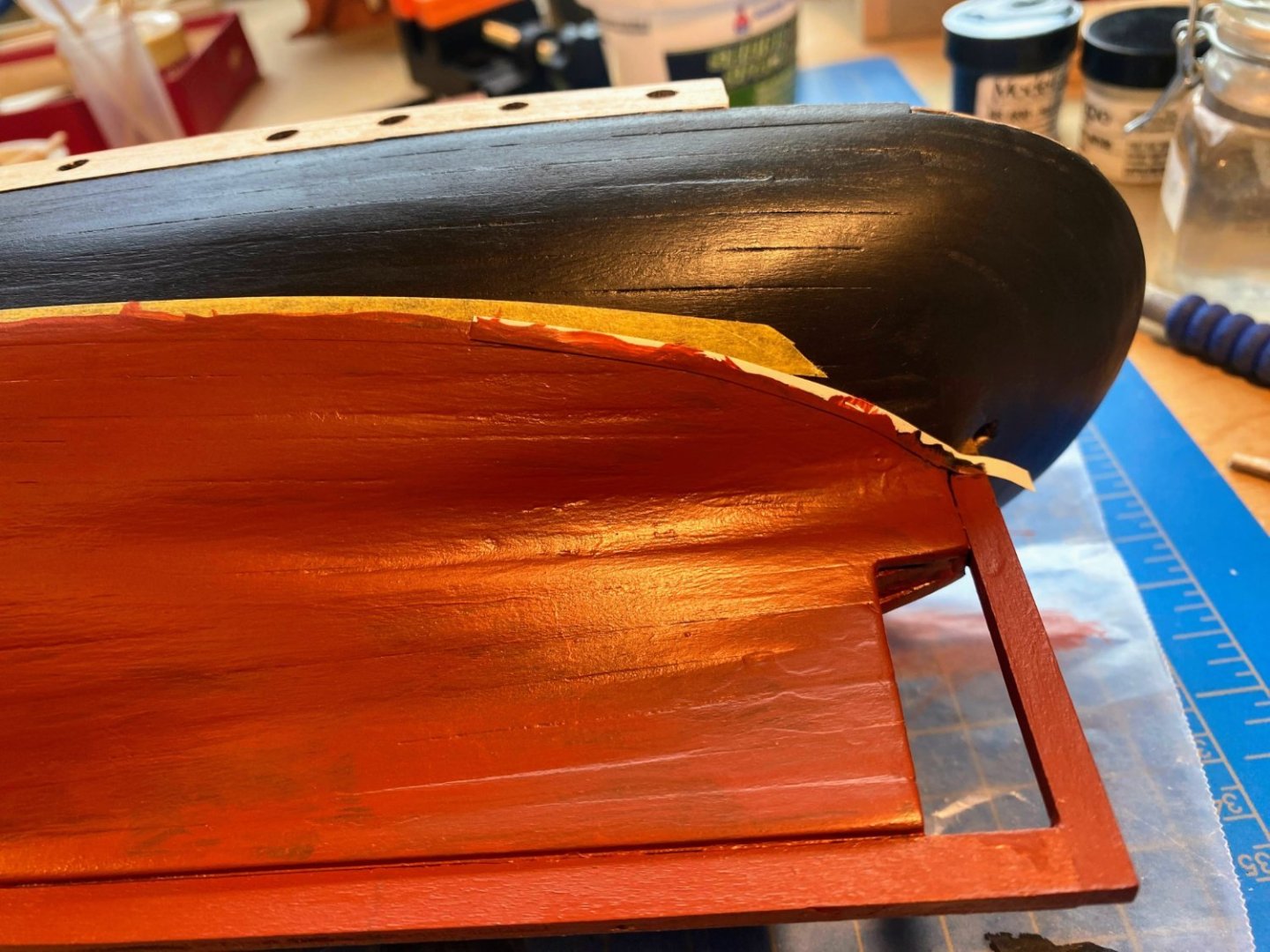
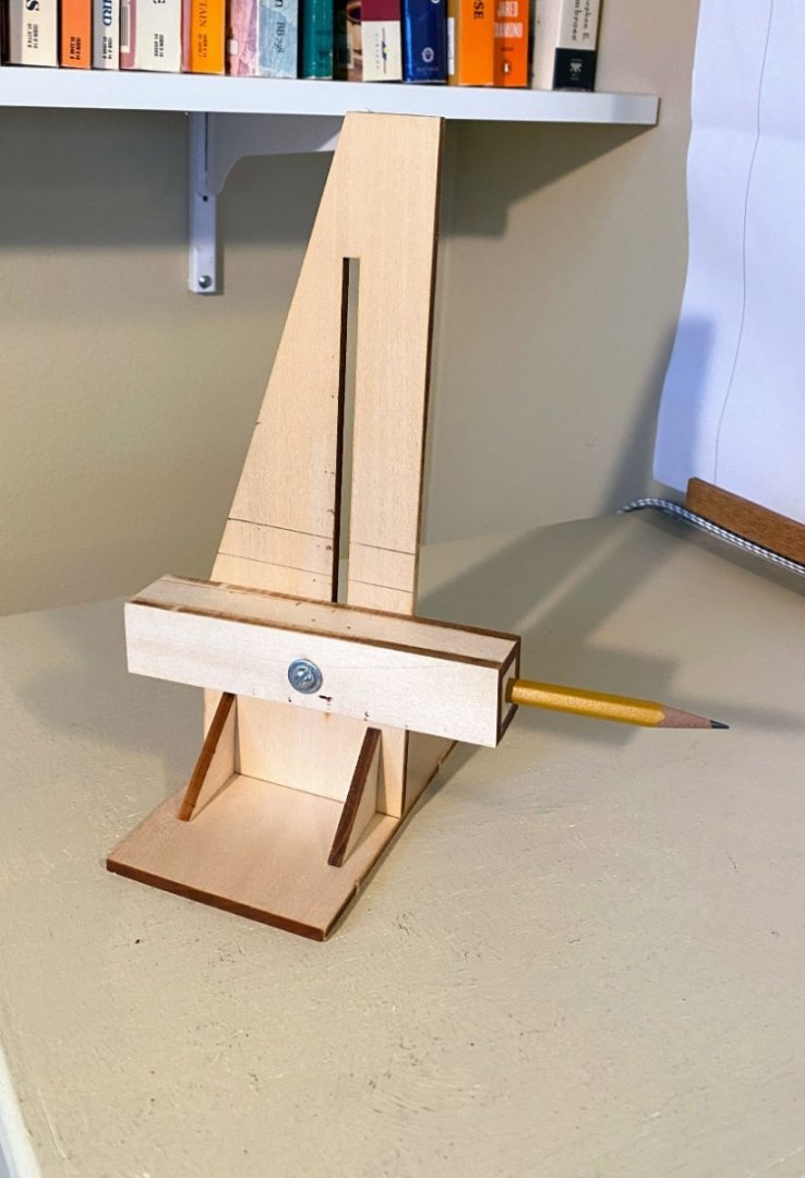
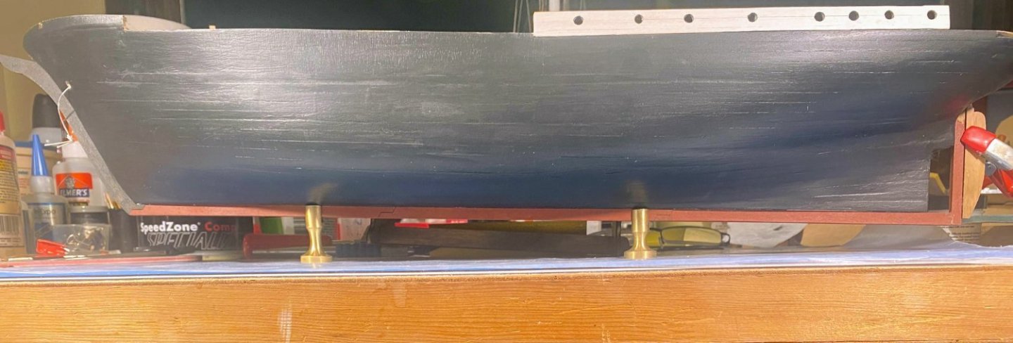
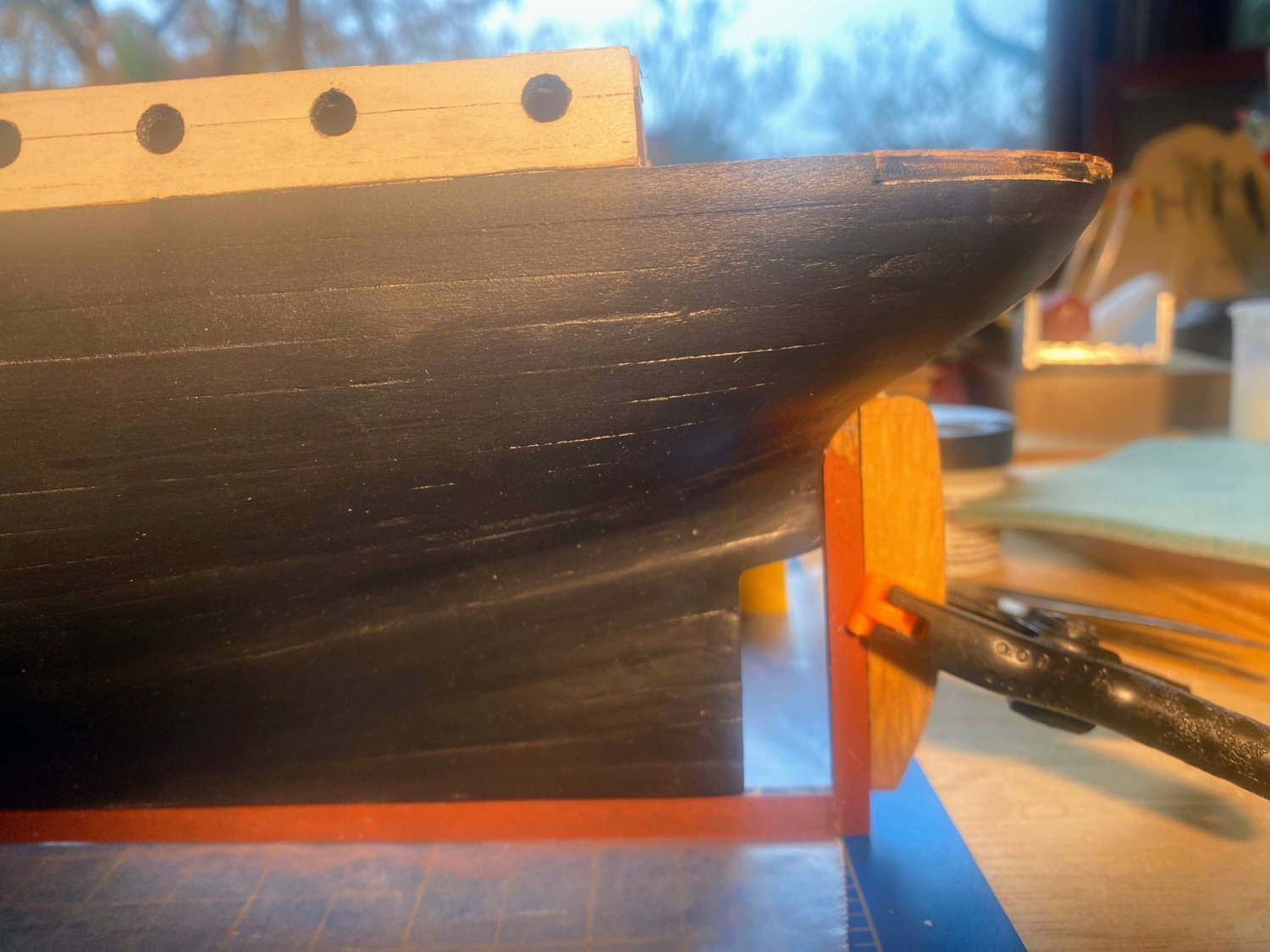
The port side lower half of the hull has been painted (two coats) and I’m generally happy with the result. The color though was not quite what I expected. Three years ago I painted the bottom half of my Spray build with what my build log referred to as Model Shipways Hull Copper Red. I don’t know whether I darkened it by adding some other paint, or whether I simply referred to the wrong paint color, or whatever, but as you can see below the color I got this time around was different from what was supposed to be the same paint back then. Not that this color is bad, but I think I like the dark, almost purple color of my Spray hull better. At least the color darkened as it dried (as can be seen below). For years I have used Tamiya’s ¼” wide yellow masking tape, which has worked quite well, but not perfectly. It handles broad sweeping curves pretty well, but not so much as the curves get sharper. Recently I learned that Tamiya has a masking tape that is more flexible, specifically designed to do curves. It is only 1/8th” wide (or at least that is the only width I could find), so you have to be careful not to slop paint over the edge not being masked. I found it to work quite well. Some time ago I read on these boards a very helpful post on how to mask and paint a waterline with minimal or no bleeding. Assuming you have painted the upper hull (or as I did, the entire hull) first, after applying the tape, paint the lower edge of the tape with color already on the hull. You can even turn the hull upside down to encourage this new paint to find any openings to bleed into. Any such bleeding will be the same color as the paint already under the tape, so no harm done. But by applying that narrow coat of paint first, you have created a seal along that edge of the tape, which should prevent any bleeding when the subsequent coats of the desired color are applied. I didn't take any pictures of that first black coat, but the technique worked like a charm for me. To the best of my knowledge, on ships such as this one with a straight keel, the keel is never parallel to the water line. Instead, moving from the stern to the stem, the keel rises toward the water line, so that the bow is a little higher (in some cases a lot higher) out of the water than the keel is. OcCre doesn’t contemplate a water line at all, so I had to rely instead on fuzzy plans found online. Using those plans, it appears that the water line rises about 1° from the rudder post to where it turns up at the stem. That distance on the model is 505 mm, and using a trigonometry calculator I found online, I determined that would be a rise of about 9 mm. When I drew my waterline (with the gadget shown below), I did my best to position the hull so that the keel rose by about that amount.
- 206 replies
-
- 6
-
-
- Endurance
- Shackleton
- (and 2 more)
-
Back in the shipyard after several weeks of pursuing other interests, including some fun travels. As HakeZou described in his build log, it appears the Endurance was some color other than black below the waterline. Model Shipways has a paint that is kind of rust colored (“Hull Copper Red”) that I used on my Spray build, and it came out a lot looking like anti-fouling paint used today on boats and ships. I recall reading when doing that build that anti-fouling paint was beginning to be used in the early 1900s, and if that is right, using this paint on Endurance is at least credible, if not accurate. I haven’t applied it to the hull yet, but I did paint the keel pieces and the rudder post that color before gluing them in place. I have also added a few more coats of black. A lot of the hull planking is evident, but for a wooden ship of that vintage, I think that’s OK. One issue has arisen. OcCre contemplates a rudder that turns on a pin that runs up its forward edge from the bottom and which is anchored to an extension of the rudder post which extends aft. That can be seen from the screen shot of the instructions seen below. But several photos and plans show the rudder attached with pintles and gudgeons, as several other builders have incorporated in their builds. That's how I plan to attach the rudder. Plans also show no extension of the rudder post to hold the pin, a pin which is unnecessary if pintles and gudgeons are used. I cut that extension off. But now the rudder seems a bit short, especially if the rudder’s top edge comes almost all the way up to the hull, which the plans seem to indicate. Perhaps I’ll cut out a slightly longer rudder, or perhaps I won’t bother. Next up, determine where the water line should be, tape it, and paint the lower half of the hull.

- 206 replies
-
- 4
-
-
- Endurance
- Shackleton
- (and 2 more)
-
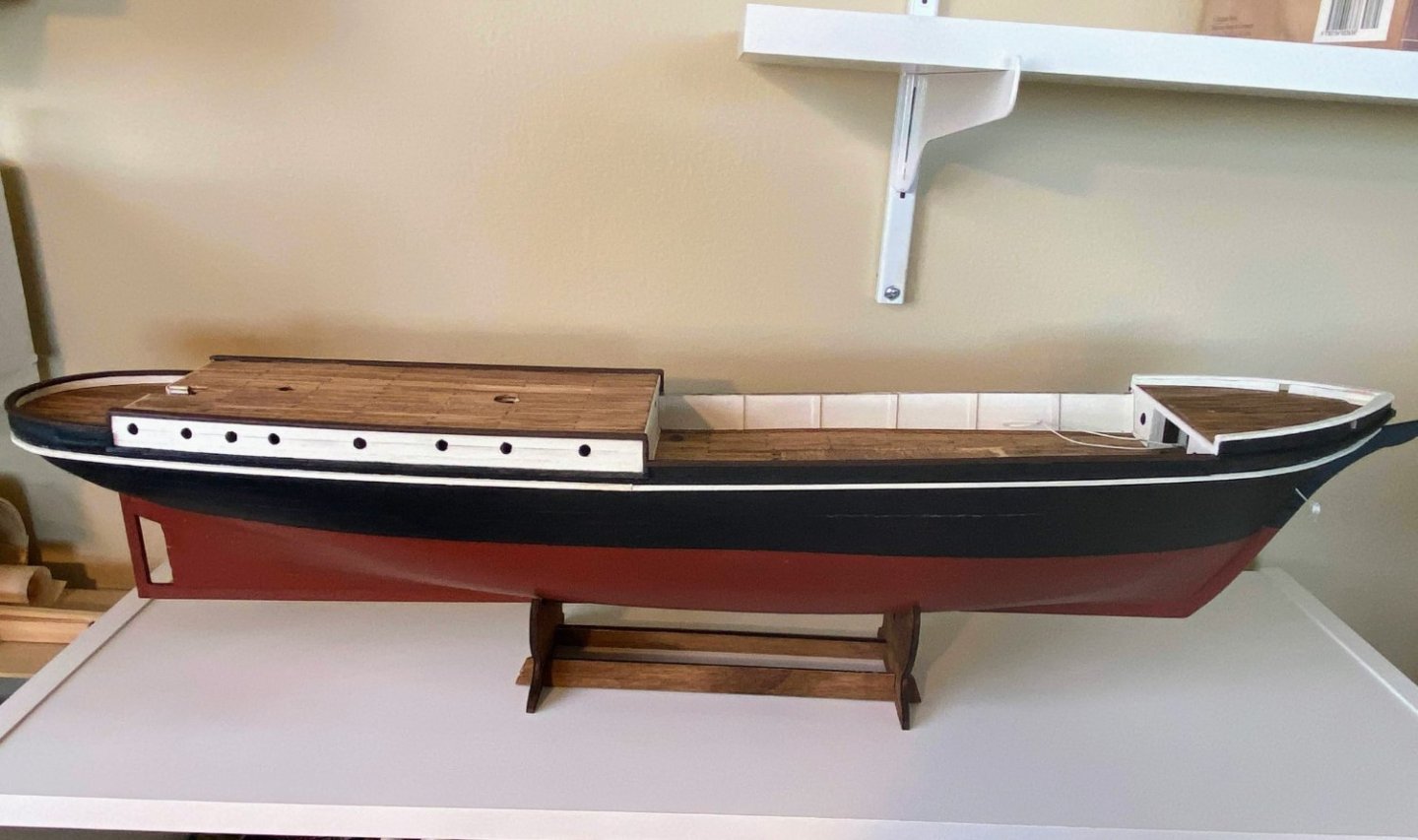
Quick update after one coat of paint and just a bit of sanding. . . I’m pretty happy with the result. If you look for it, you can distinguish the area of planking from the plywood bulwarks, but it’s not that obvious. There is still some more filling and sanding to be done, which is not evident in these photos, and of course several more coats of paint. Rewarding though to see some meaningful progress shortly after many weeks of planking.
.thumb.JPG.f98099c1262d39aebab0728bcb0d97cd.JPG)
.thumb.JPG.35ea2c1e0763f04fda9c2cd8ed915cd5.JPG)
- 206 replies
-
- 6
-
-
- Endurance
- Shackleton
- (and 2 more)
-
Nice work Josh. I particularly like the idea of planking the tops. I will copy (intending it to be the best form of flattery). Rigging isn't all that difficult, if you have plenty of patience. I sometimes find myself staring at the model, or the plans, or both, for many minutes, just thinking things through.
-
Thanks Bob. Yes, definitely putting some miles on my bike, but also learning how to play golf. A case could be made that that is a crazy thing to do at my age, but I'm enjoying the heck out of it. I don't keep score, which makes it hard to get frustrated. 😛
-
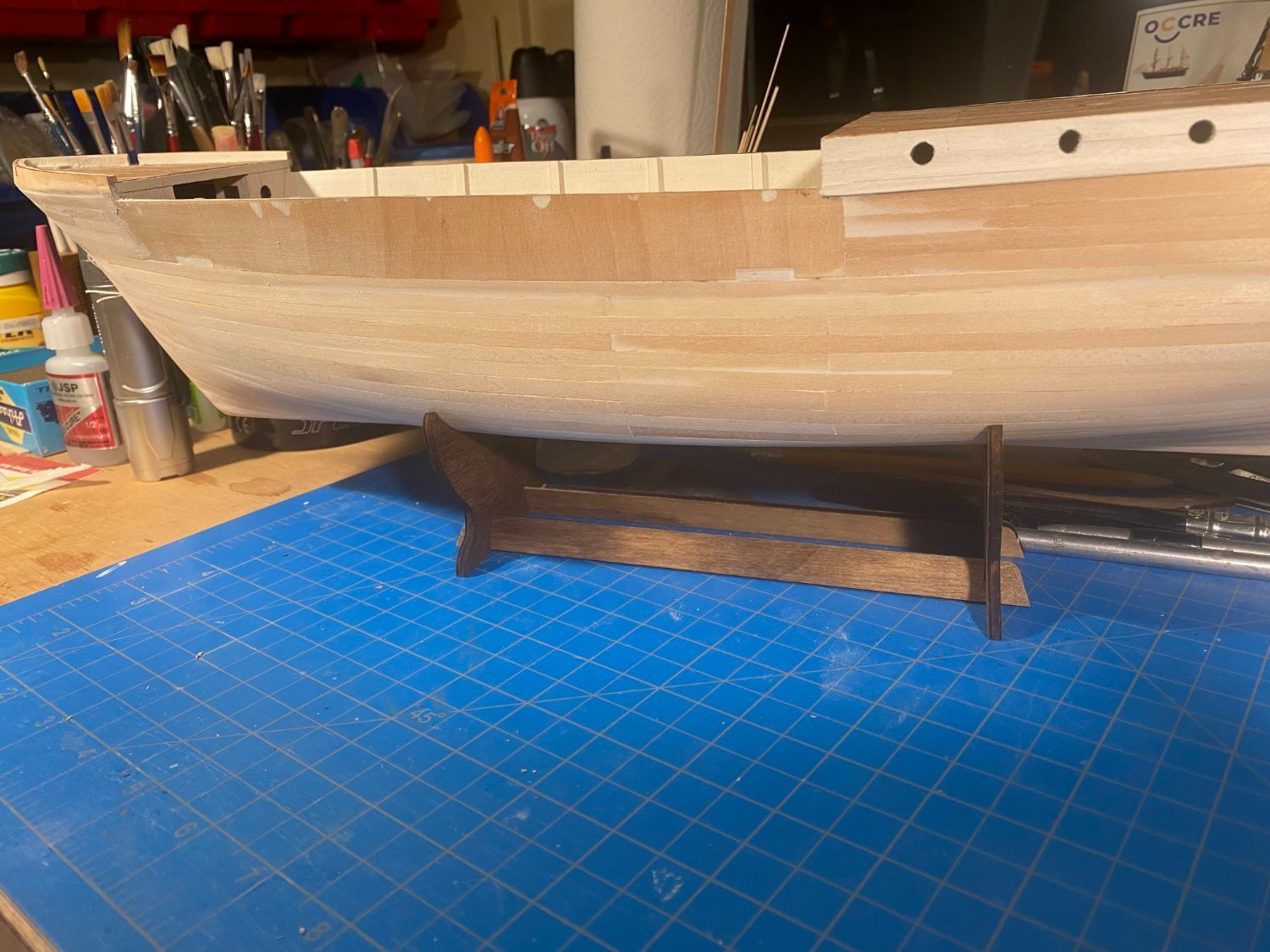
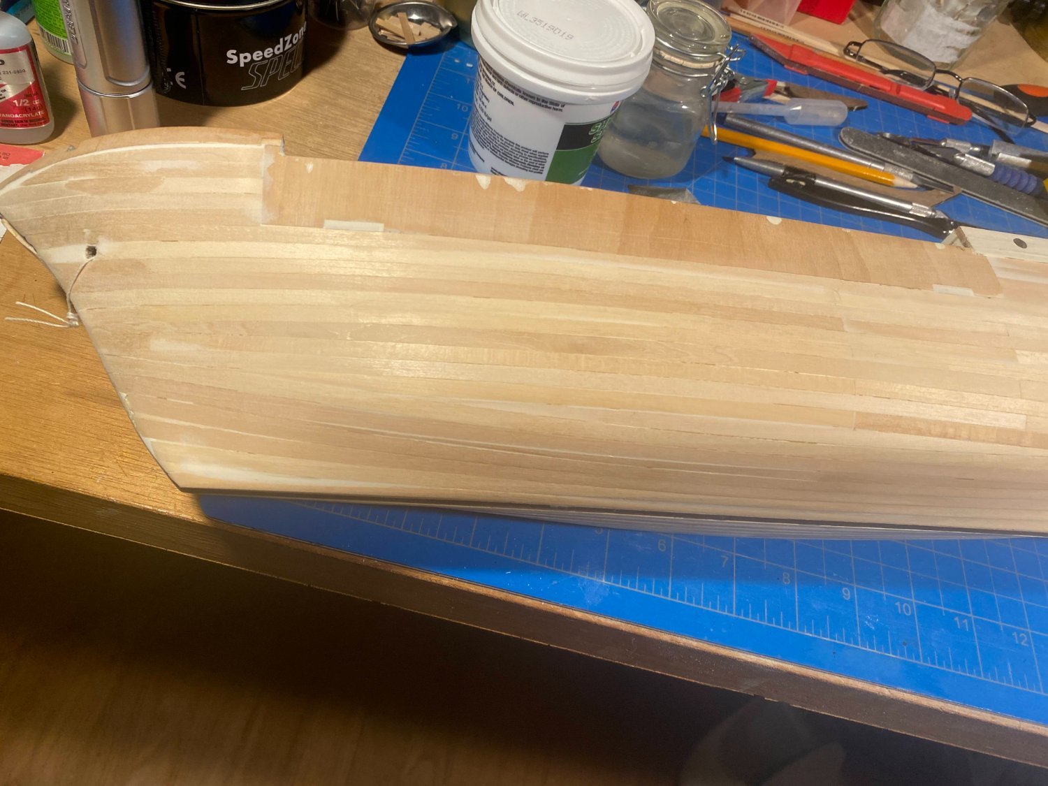
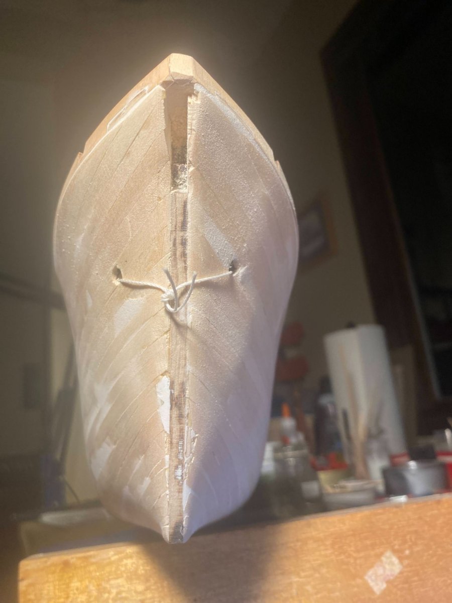
Progress in the shipyard has slowed considerably, and likely will for a while, as delightful, mostly smoke-free weather is keeping me doing other things I love to do outdoors. I have though done enough sanding and filling to move on to painting. As I mentioned previously, a number of what look like rough areas in the photos actually feel quite smooth. After that first coat goes on, I’m sure I’ll find some more filling needing to be done. My plan is to try to get all the additional filling and sanding done before putting the stem, keel and stern pieces on, then paint them along with subsequent coats of the hull. I’m also going to need to dry fit the bowsprit in place and do some cleanup of the planking mess above the stem piece.


- 206 replies
-
- 6
-
-
- Endurance
- Shackleton
- (and 2 more)
-
Would you buy pre-owned wooden kits?
Tomculb replied to Frank Burroughs's topic in Wood ship model kits
A couple of anecdotal thoughts: While the selection is very limited, I would always start a search for a pre-owned kit in this forum on these boards. Your odds of finding a knowledgeable, communicative and honest seller have got to be better than on eBay. Several years ago I bought Model Shipways discontinued solid hull model of the Yacht America here and was very pleased. As a newbie you might also want to take a look at Midwest Models boat kits. They went out of business but seem to be back, probably under new owners. I bought and built their Peterboro Canoe kit and really enjoyed it . . . and learned a lot. They have quite a variety of small boat model kits. -
Nice work Josh. You are now unquestionably well ahead of me, and now I have the privilege of following you. I like the idea of at least a hint of planking showing through the paint. After all, ships of that era and the centuries before weren’t made of steel, and certainly weren’t made of fiberglass. But on my model, where I’ve decided not to add a layer of veneer over the first layer of planks, I don’t want it to be obvious that the bulwarks are plywood and not planked. So my challenge is to have the hull end up pretty darned smooth, but not so smooth as to make it look like fiberglass. Filling and sanding the stern hasn't been as difficult as I anticipated, but of course I won't know for sure how effective I've been until it's painted. Finishing up the filling and sanding of the rest of the hull is what I’m working on now. I expect (hope) to get my first coat of paint on within the next couple of weeks.
-
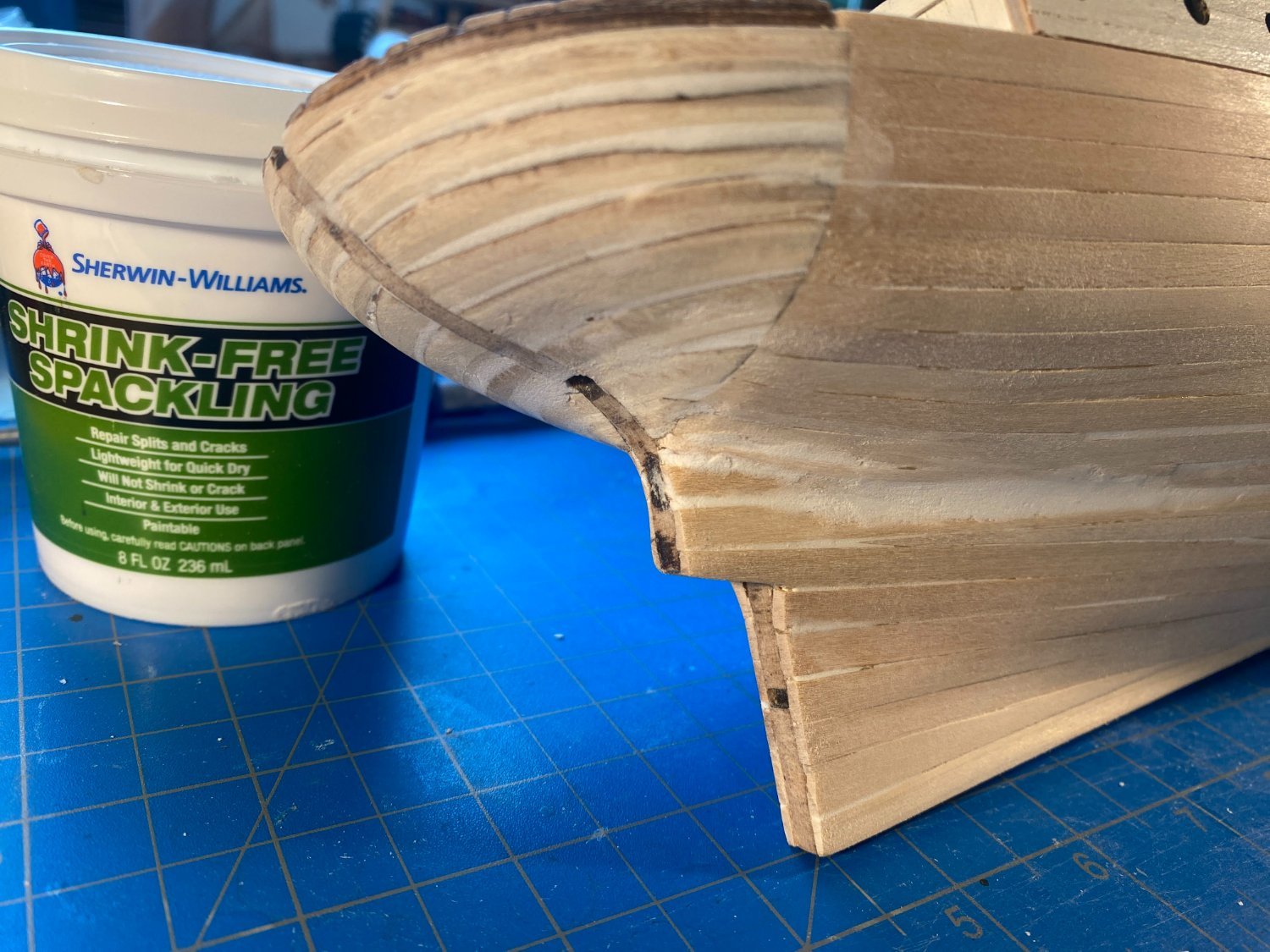
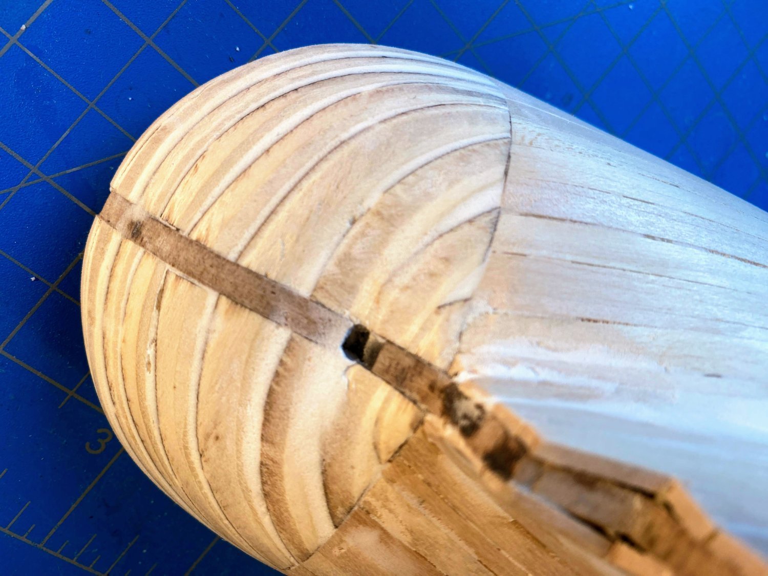
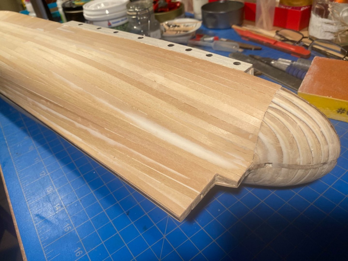
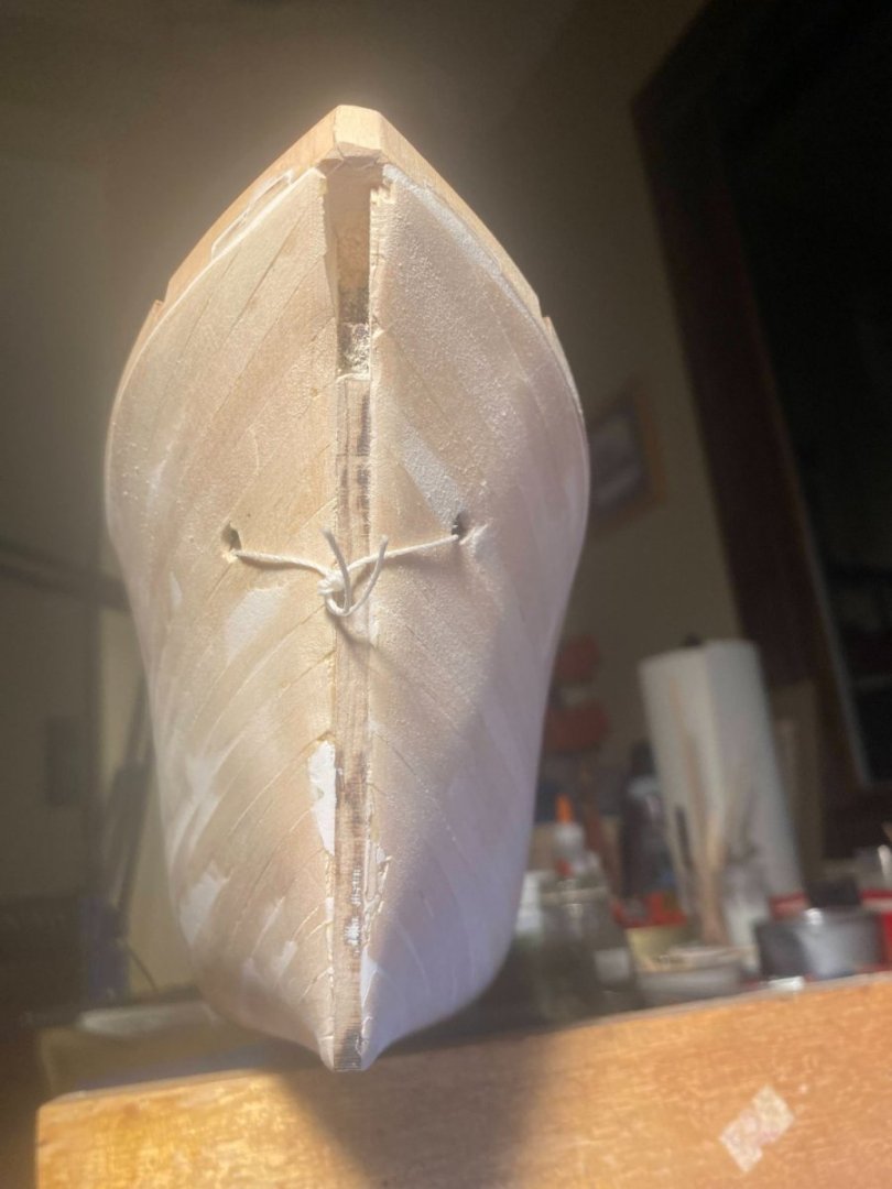
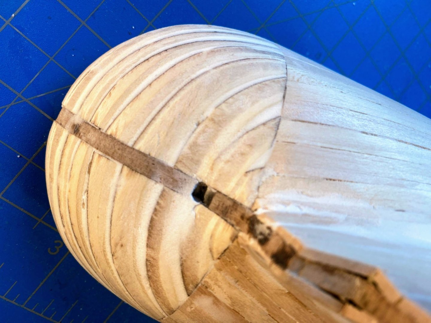
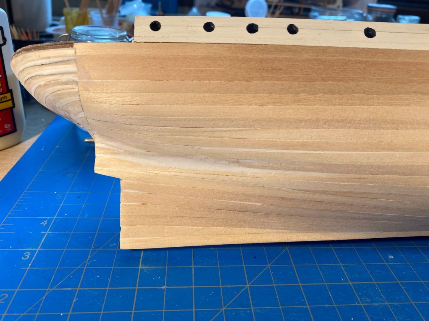
I have shaped, filled and sanded the stern’s bread and butter sandwich, a task that didn’t take as much time and wasn’t as difficult as I expected. And I have done some filling and sanding of the first 3 or so inches of the hull forward of those stern pieces. Interestingly, the stern feels a lot smoother than it looks in the photos, and the hull needs a lot more work than appears in the photos. Somewhere I read (I think it was a post by Nick from BlueJacket) recommending spackle for filler rather than regular carpenter’s wood filler. I tried it, and it seems to fill just as well as the wood filler I had used previously, but it sands more easily. I found in a closet in our basement both spackle powder, which needs to be mixed with water, and the product in the first photo below, which is a spackle paste. It can be applied with a small spade or with a wet finger. It’s working pretty well for me.

- 206 replies
-
- 5
-
-
- Endurance
- Shackleton
- (and 2 more)
-
Here's what I'm planning to do for a windlass. The photo is what I did with BlueJacket's Spray kit. The windlass drums were supplied with the kit, and can be ordered separately from BJ and probably others. The center part is just a piece of wood I shaped. For Endurance I'll paint it all black. Not much detail, but good enough (for me, anyway), since it won't be very visible under the anchor deck. But at least there will be something there looking a little like a windlass.


.JPG.2cea38412a6e1c74c3a18f509aff0ac9.JPG)
.JPG.142202bcc21cd87a0b844dc8ada8e483.JPG)