HOLIDAY DONATION DRIVE - SUPPORT MSW - DO YOUR PART TO KEEP THIS GREAT FORUM GOING!
×


Tomculb
-
Posts
341 -
Joined
-
Last visited
Content Type
Profiles
Forums
Gallery
Events
Everything posted by Tomculb
-
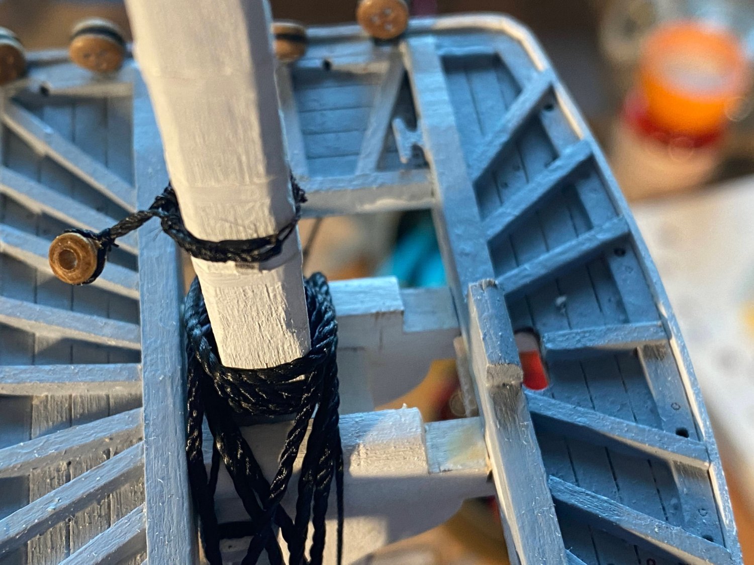
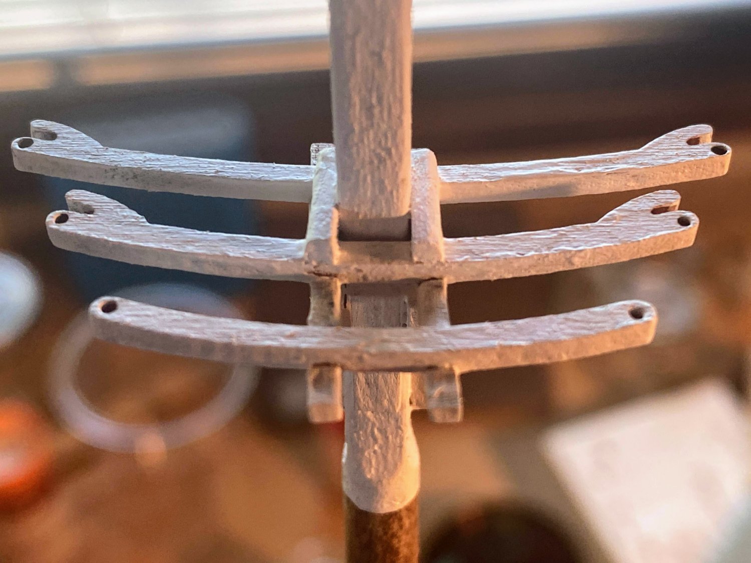
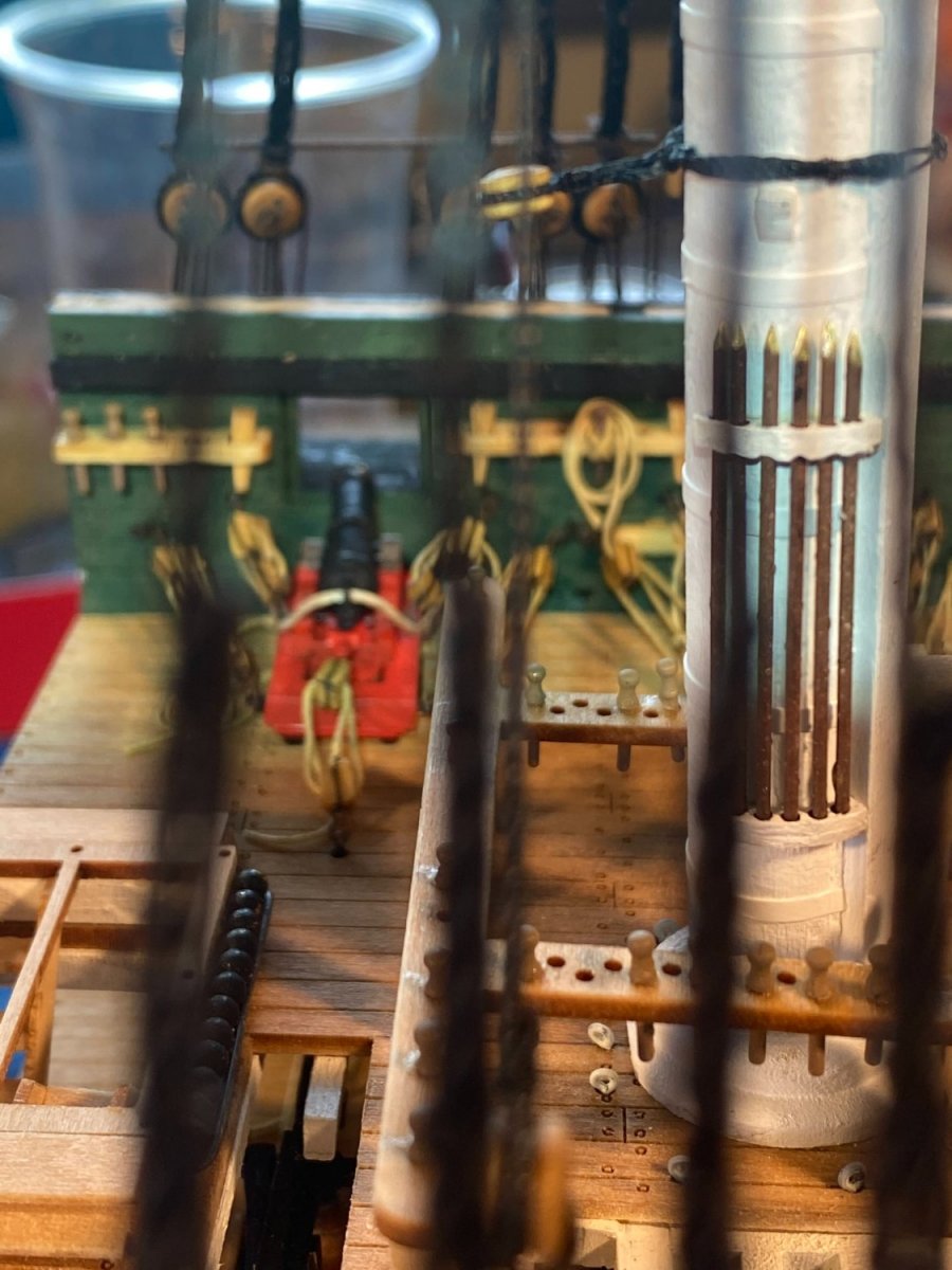
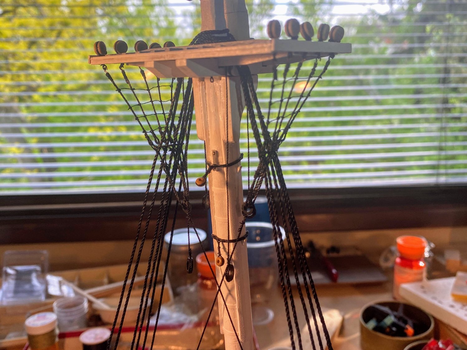
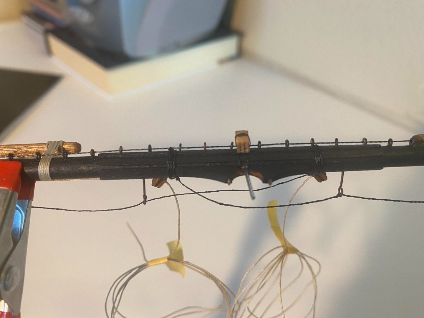
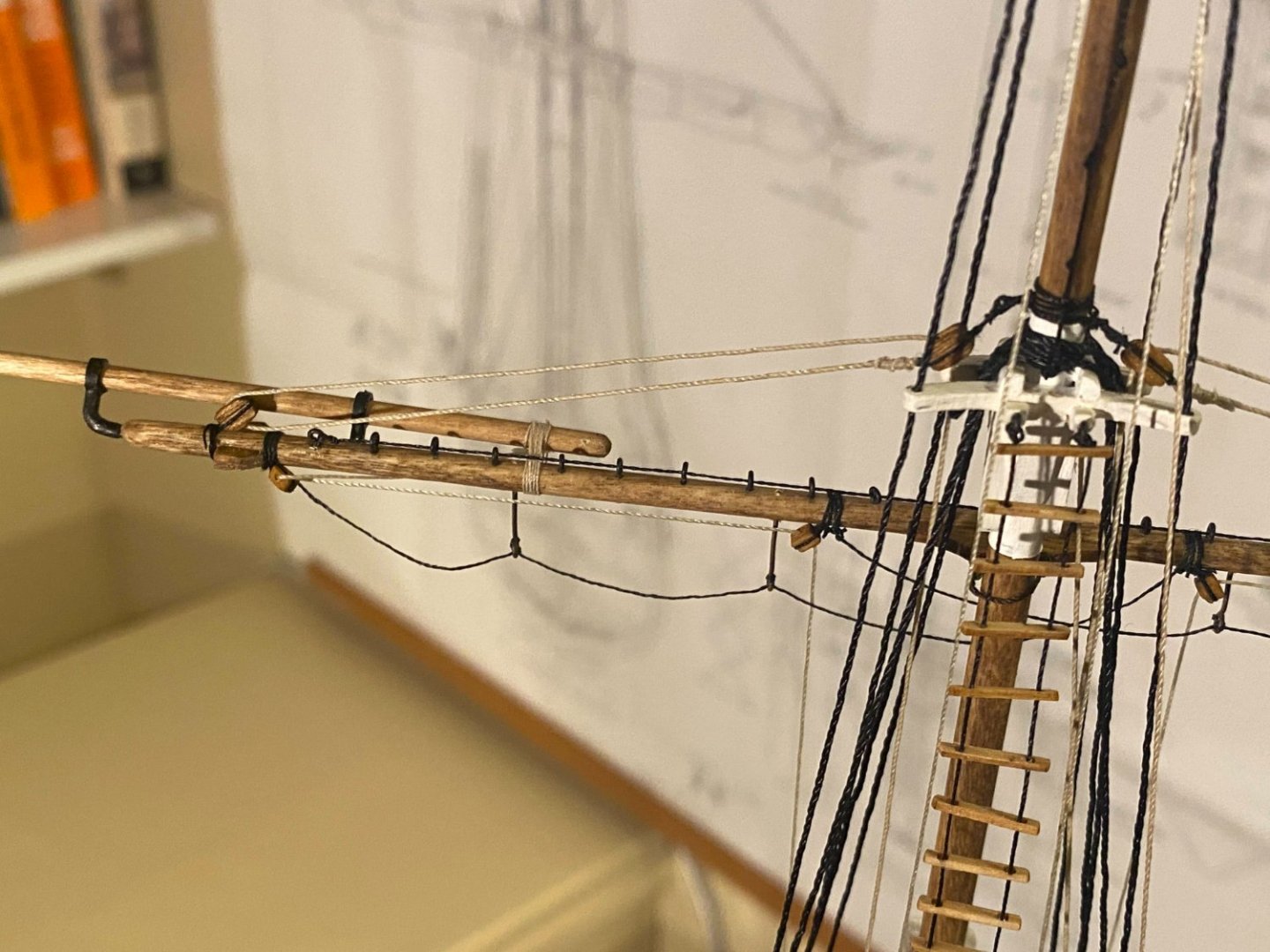
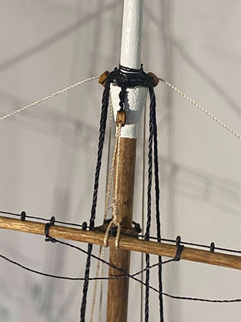
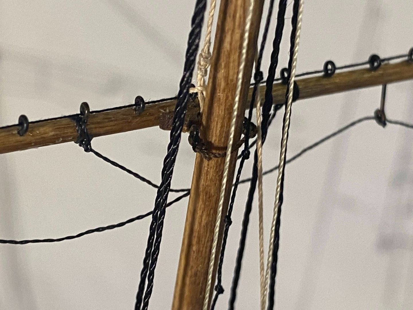
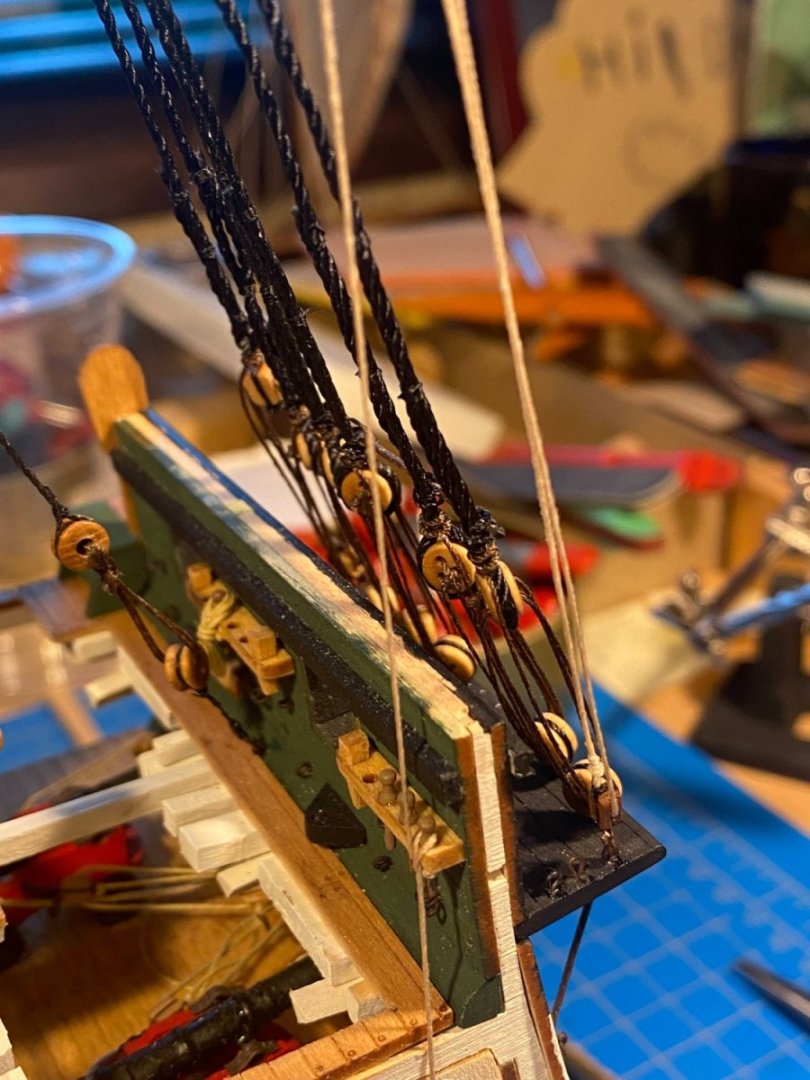
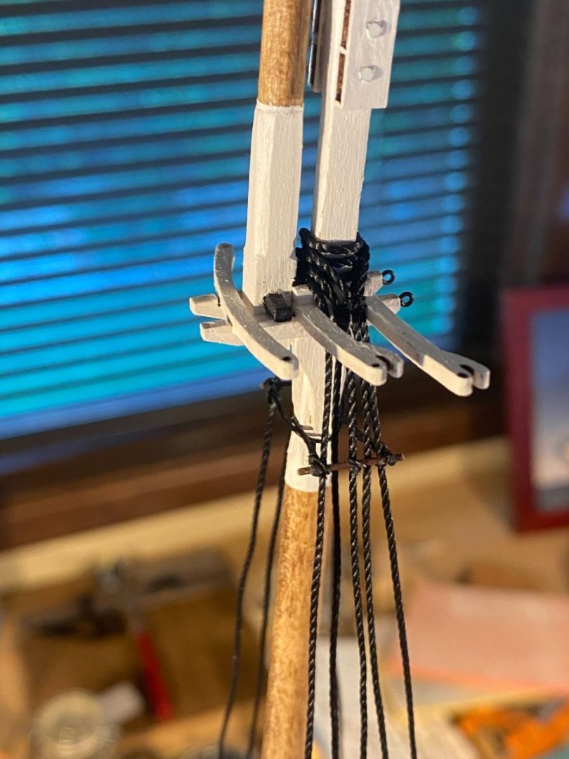
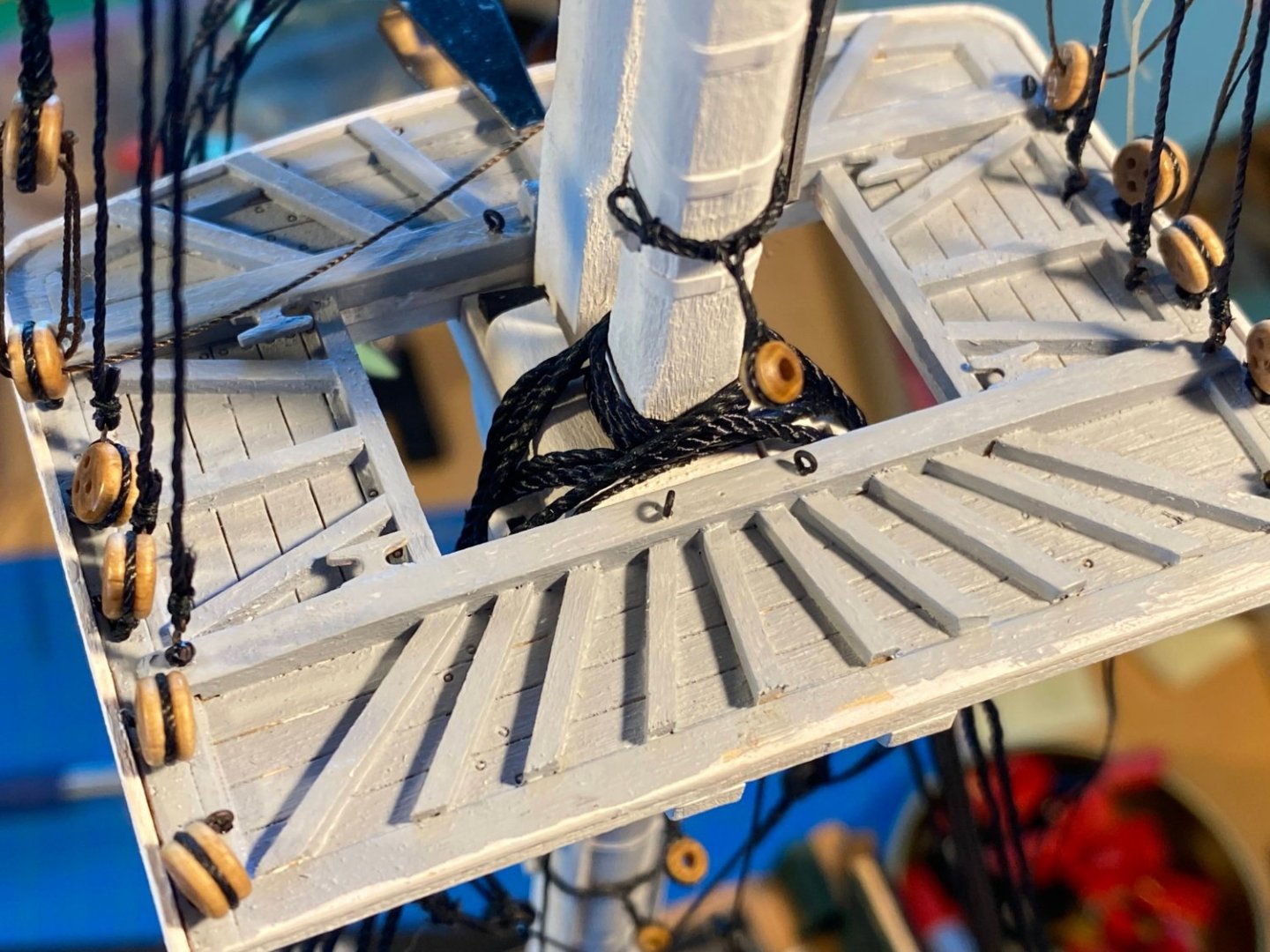
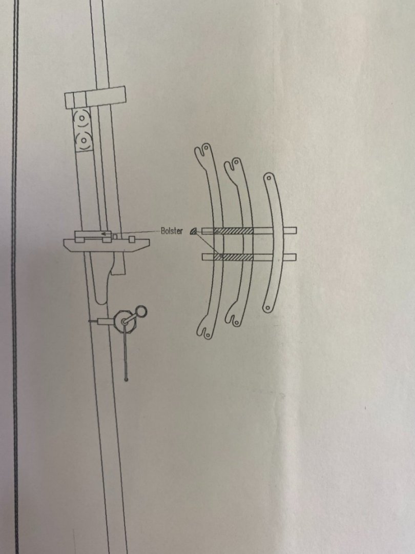
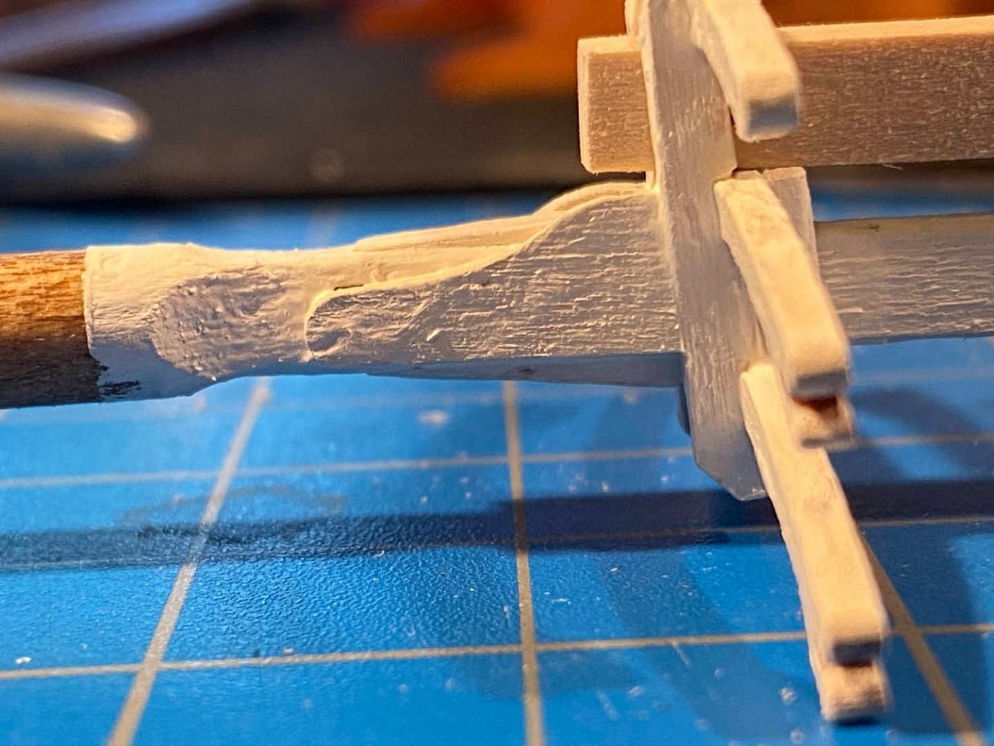
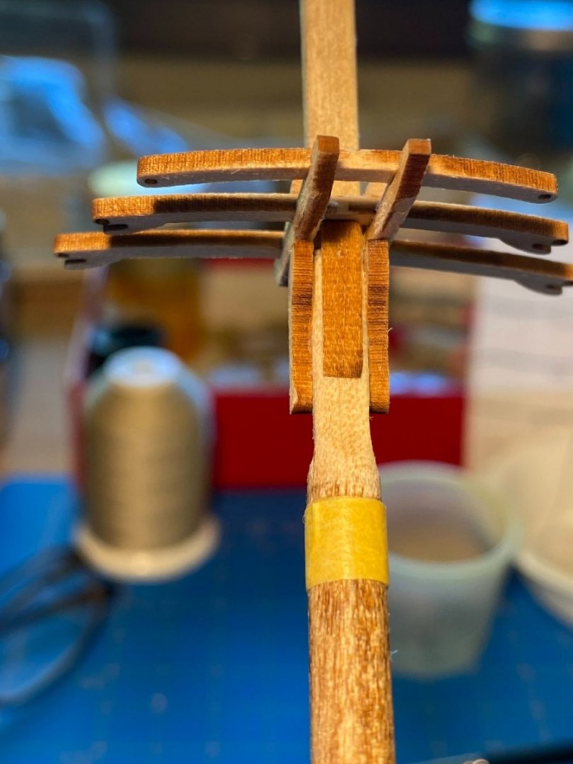
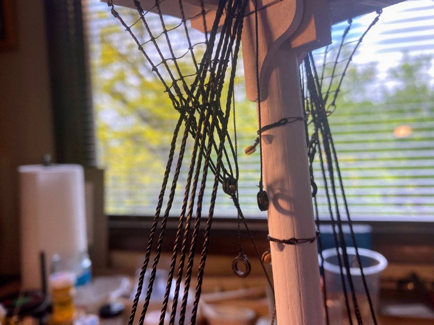
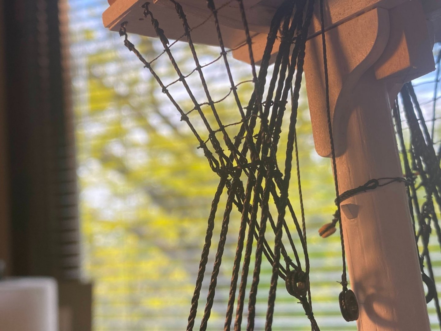
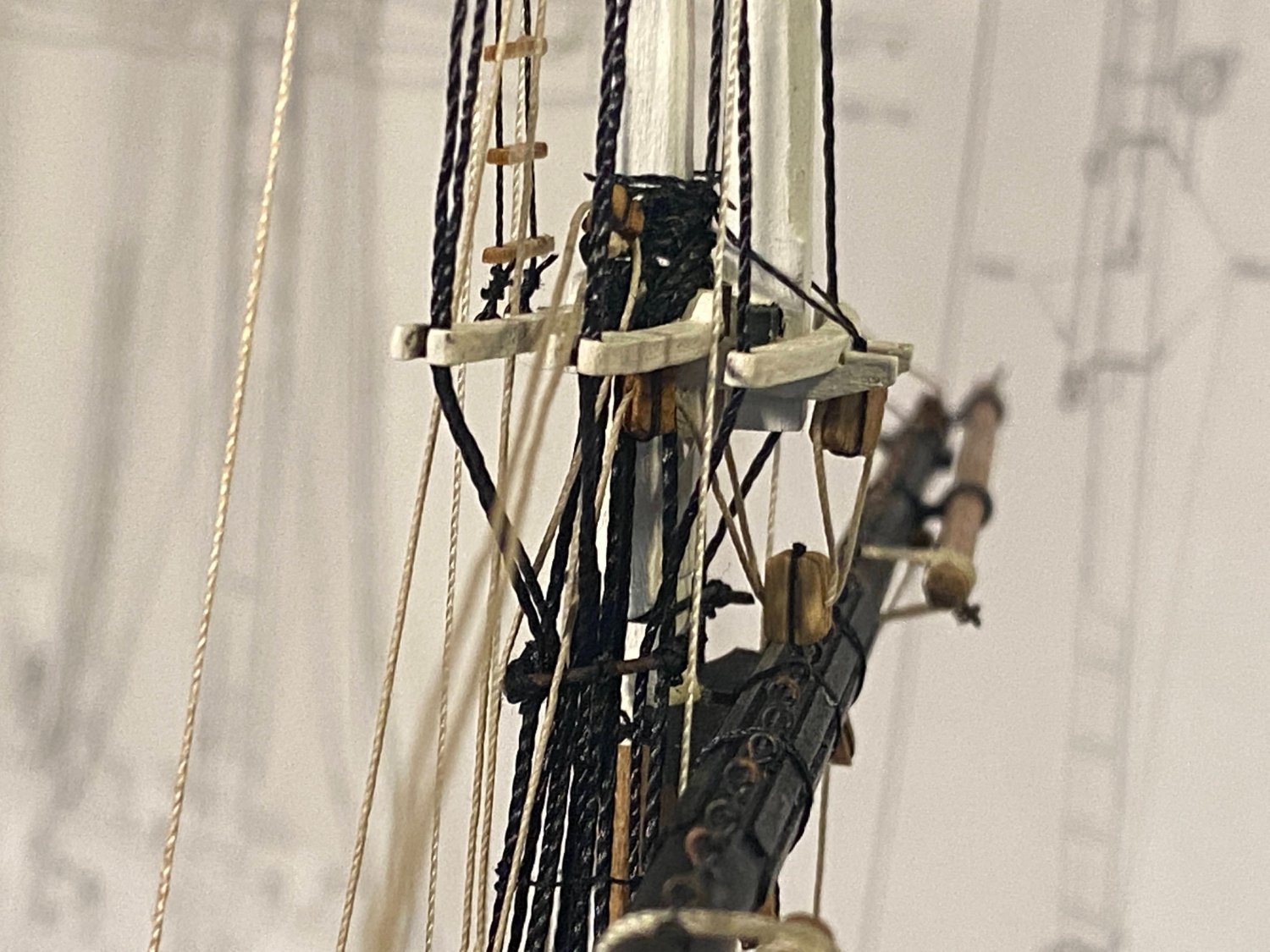
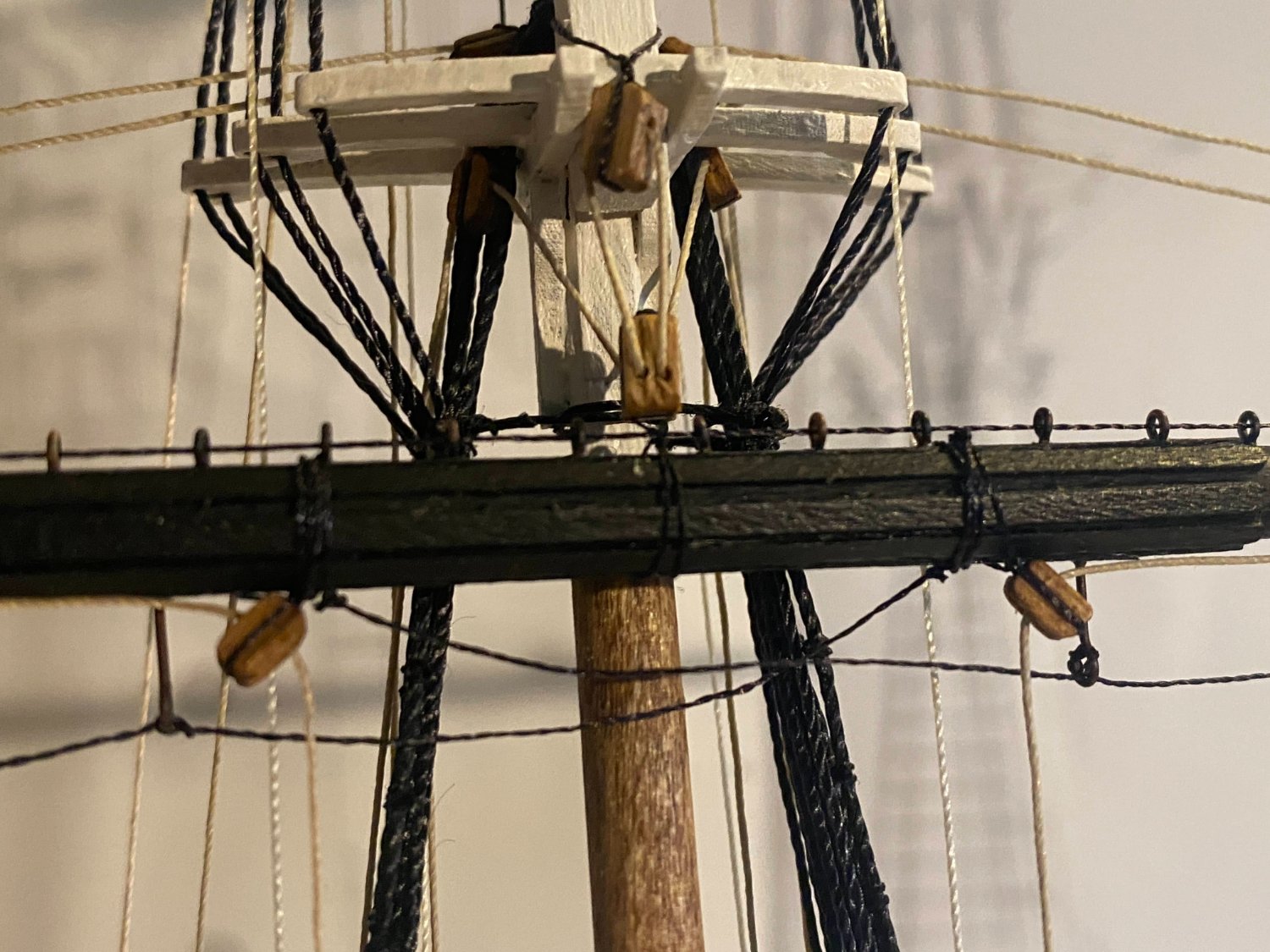
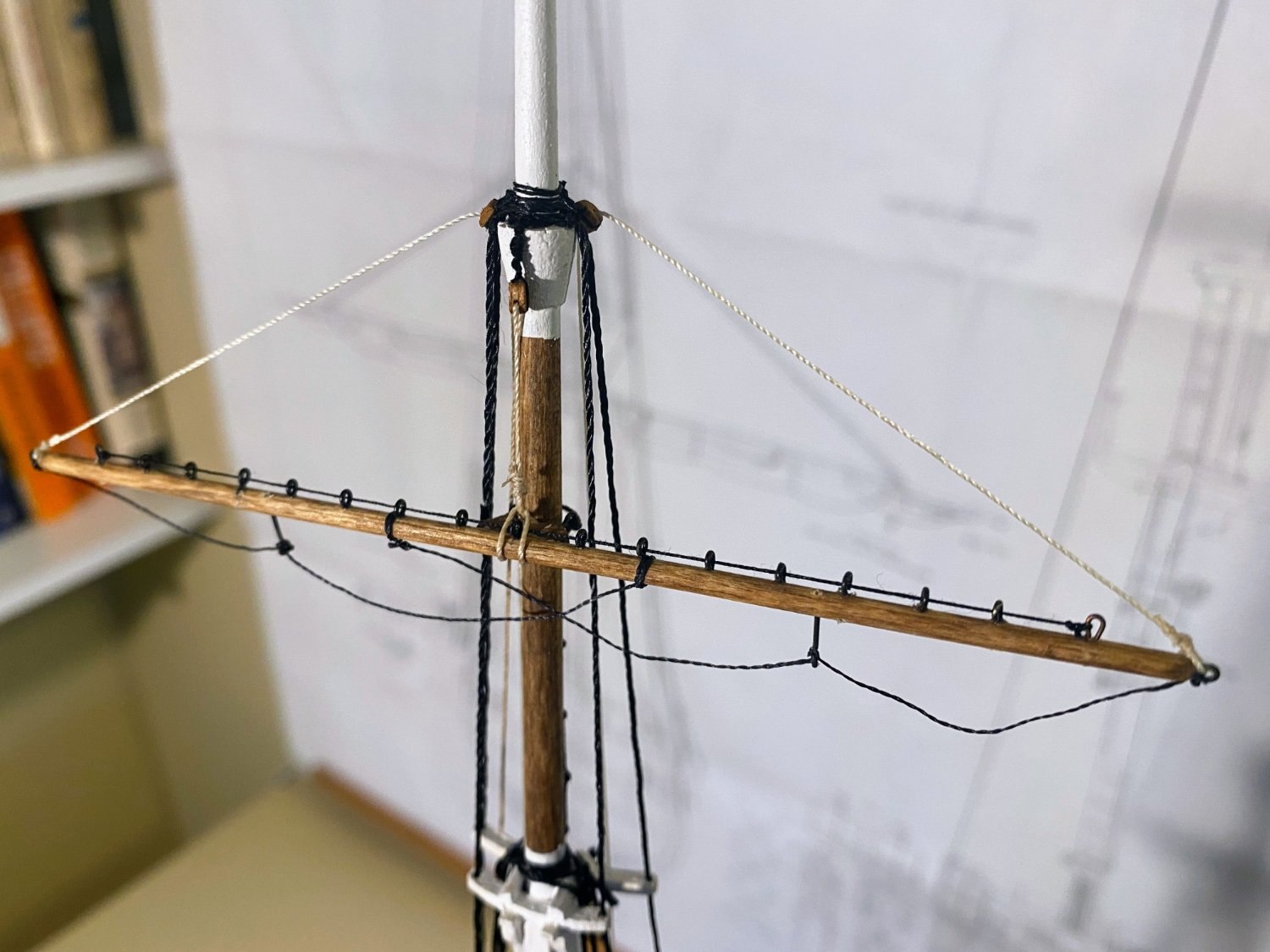
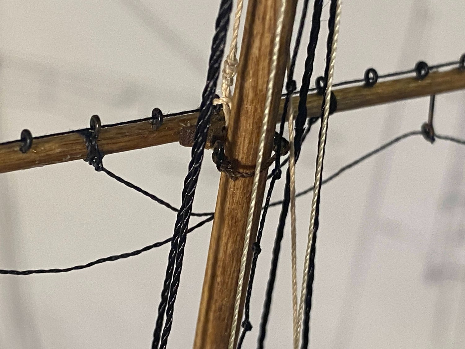
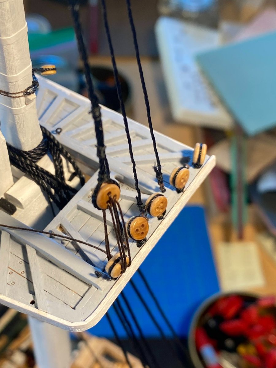
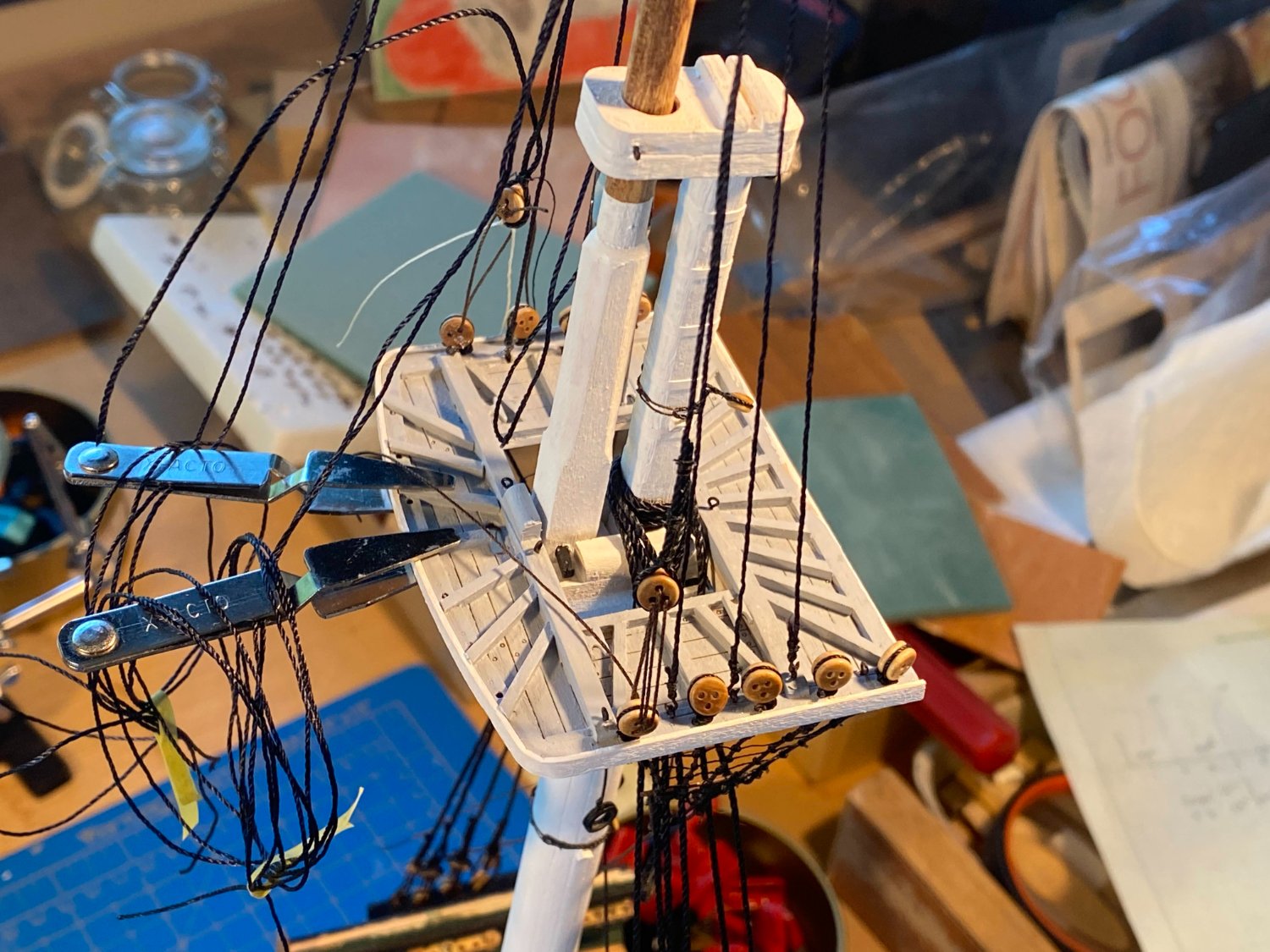
 Thanks again Henry. For some reason your description of the truss rigging didn't sink in the first time, compounded by the fact that my understanding of "cleat" has been limited to a squat T-shaped thing you tie a line to. But I see now that it can also mean the enclosure of a sheave, or without the sheave, the enclosures on the forward side of the yard that locate the trusses close to the yard as they wrap around it. In any event, you describe each truss passing through the thimble of the other truss after it has gone forward to wrap around the yard and then comes aft again. That makes more sense, since that means both parts of the truss are pulling the yard into the mast, rather than having one part pulling on it diagonally upward as shown in the plans. Here is how the instructions show the trusses passing through the thimbles on the aft side of the mast, before they have wrapped around the yard. I'm learning a lot . . .
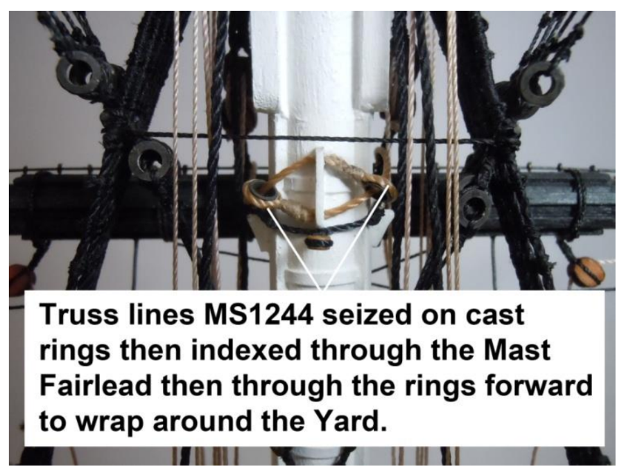
- 163 replies
-
- 2
-

-
- Model Shipways
- Constitution
- (and 2 more)
-
Thanks Henry for your comments on terminology. That’s very helpful. “Jeers” is a term I was not familiar with, but looking at Biddlecombe, that’s exactly what is in blue, as you pointed out. The book defines jeers as “Tackles by which the lower yard of a ship are hoisted along the mast to their usual station, or lowered from thence . . . “. As you described them, the truss and the preventer sling appear to be correctly labeled as I used them, but not as used in the instructions. I’m not sure what you mean by the “cleat with the sheave on the trestle trees”. As shown on the plans, there is a sheave on the trestle trees, but no cleat there. The only cleat the trusses encounter is in the top. The only sheaves are the ones attached to the trestle trees, and it seems to me they need to be used to properly direct the truss pendants to the blocks hanging from the mast cap. Am I missing something? Two more terminology issues. First, I have at various times used the term “jig” to refer to a block and tackle assembly, but only because that is the term used in the instructions. I don’t recall seeing that word used that way before. The term I would be inclined to use is “tackle”. Second, the line that is pulled to extend the studding sail boom outward is referred to in the instructions as a “halyard”, but previously I had never seen that word used for anything other than a line that pulls something vertically (e.g. a sail or a yard). I would be more inclined to use the word “studding boom outhaul” or “studding boom outhaul tackle.” I welcome your (or anyone else’s) comments, and thanks again for your insight.
- 163 replies
-
- 2
-
-
- Model Shipways
- Constitution
- (and 2 more)
-
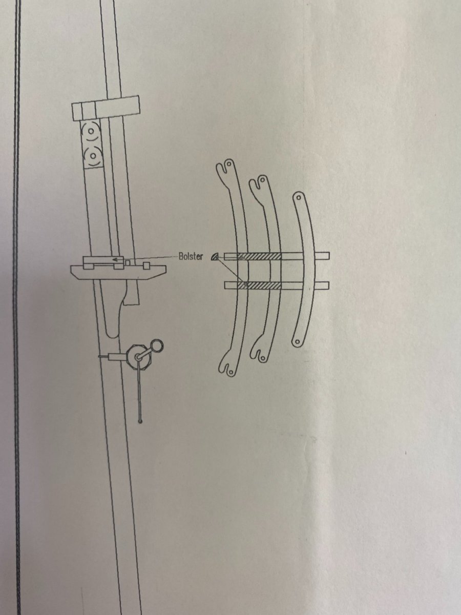
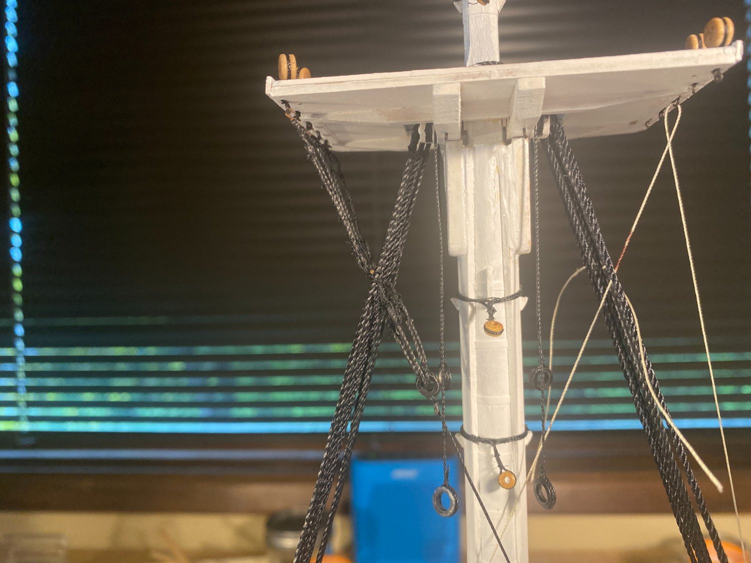
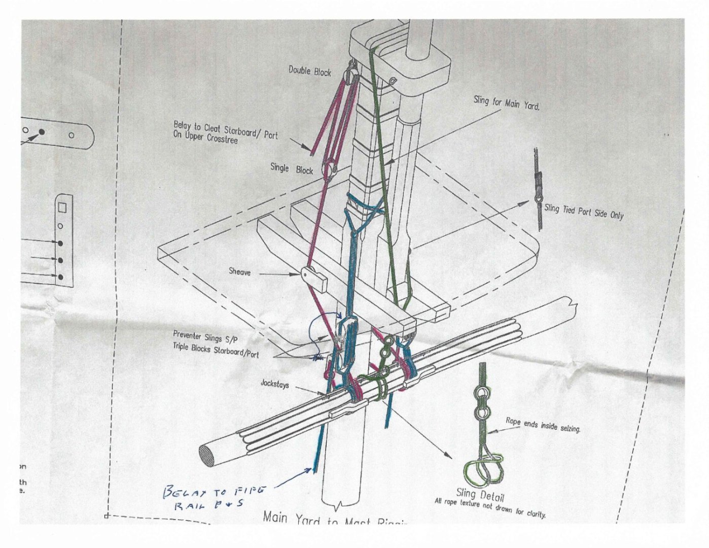
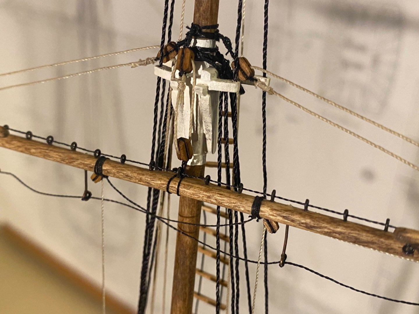
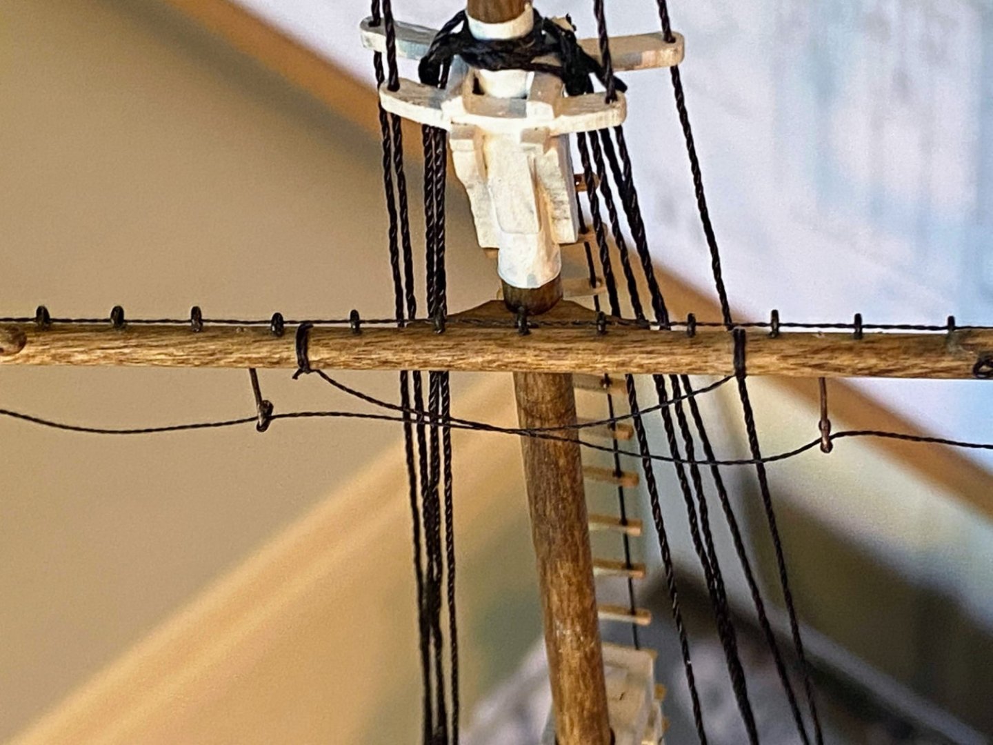
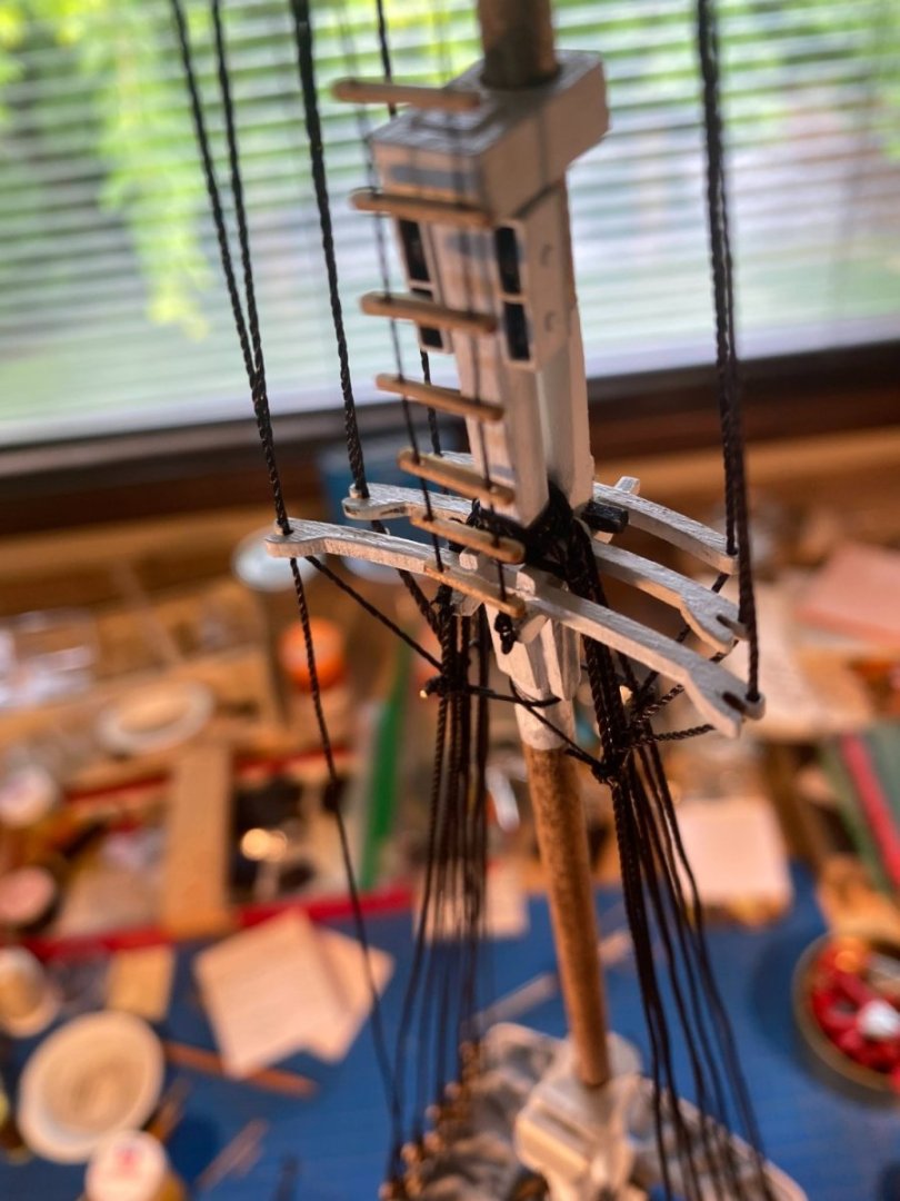
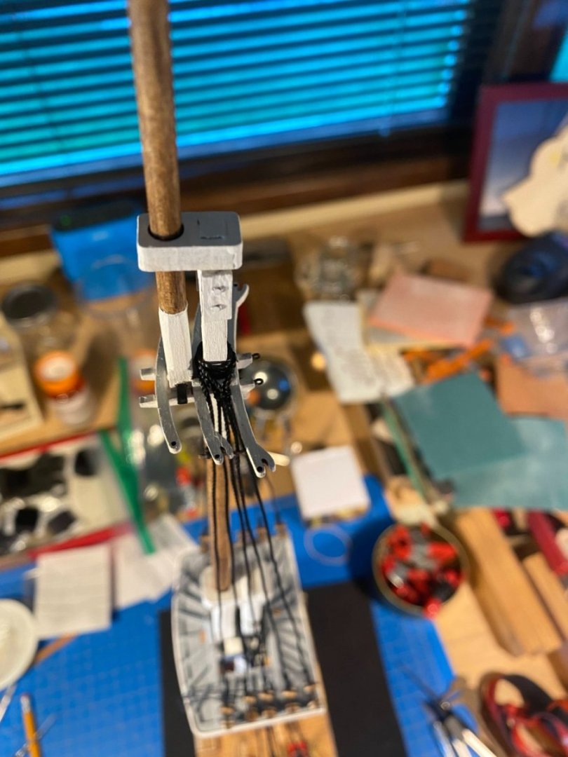
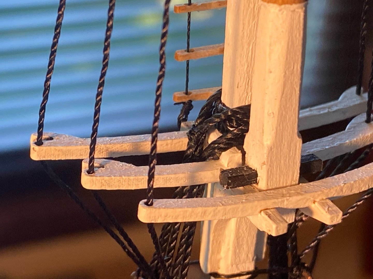
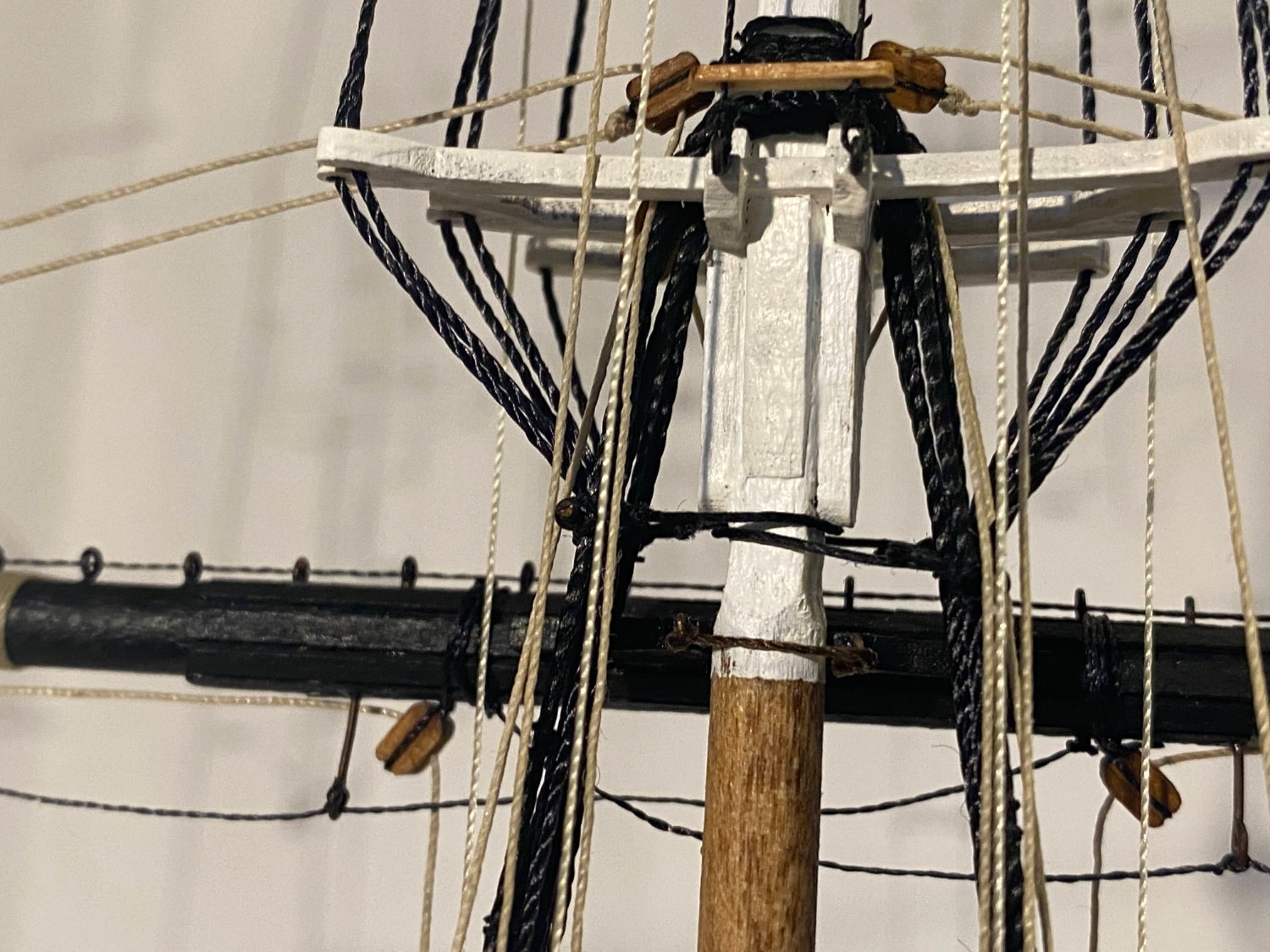
Construction of the main (or lower) yard is basically the same as the topsail yard, only larger (52 eyebolts for the jackstay!). And rigging of the lifts and studding sail booms is the same (and straightforward). But things really get complicated when it comes to the preventer sling(s) and trusses. I am just about ready to attach the yard to the mast and then start on its rigging. Over the last few weeks when I’ve had some down time (usually waiting for something to dry), I have studied the plans (repeatedly) and read the instructions (probably only twice) trying to figure out exactly what is supposed to happen here. I think I’ve figured it out. I took a picture of the plans’ detailed depiction of the rigging which holds the yard to the mast and used some colored pencils to differentiate the three elements of this rigging. The instructions refer to two preventer slings and a truss, but I think it would be more accurate to label two of them as trusses with just one preventer sling. I have a copy of The Art of Rigging by George Biddlecombe, first published about 100 years ago, and he defines “preventer” as a rope “employed sometimes to support, or answer the purpose of, another that has a great strain upon it, or is injured . . .”. My translation is that it is somewhat analogous to a seat belt; that is, it doesn’t do anything unless something bad happens. If I’m right about that, there is only one preventer sling, and that is the standing rigging (instructions say use black thread) shown in green in the picture of the plans above. Biddlecombe defines “truss” as “a rope employed to confine and slacken the lower yards to or from their respective masts.” That sounds like adjustable running rigging to me, and the instructions say use beige thread for these. There are two pairs, one shown in red above and the other in blue. The red ones are for pulling the yard against the mast, and I think of them as horizontal trusses. The other pair is for adjusting the yard up and down, and I think of them as horizontal, or perhaps even halyard, trusses. Those are shown in blue. The one thing that is not made clear above are the ends of what I have called the horizontal trusses (in red), where they attach to the aft side of the mast. There is a good picture on the top right side of page 87 of the instructions that provides some clarity. Basically each line passes through a hole in the fairlead already installed on the mast back there, then through an eye at the bitter end of the other line, then forward to take a loop around the yard, then up through the sheave on the side of a trestle tree, and on up to the jig attached to the underside of the mast cap. Once it leaves the yard, what is shown on the plans is pretty clear. I’ll post more details and pictures as I install this rigging.
- 163 replies
-
- 3
-
-
- Model Shipways
- Constitution
- (and 2 more)
-
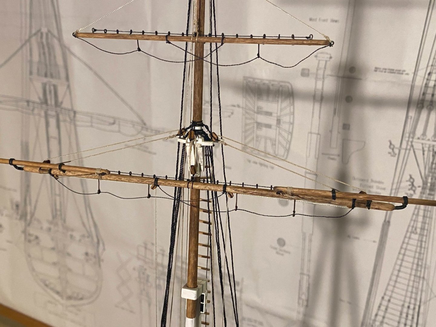
A question for you Connie history buffs as I near completion of my build of the main (or lower) yard . . . The plans show Flemish horses (extensions of the foot rope) out at the ends of the main and topsail yards, with the notation "Optional detail based on period being built." Do any of you know what period of history Flemish horses were common? I assumed that had something to do with studding sail booms, since those booms would be hard to reach without a Flemish horse. But the plans show the topgallant yard with studding sail booms and no Flemish horse, and the real Constitution (as of the date of Google Maps videoing) has Flemish horses and no studding sail booms. Some of you have a lot more insight as to issues like this than I do. Thanks
- 163 replies
-
- 1
-
-
- Model Shipways
- Constitution
- (and 2 more)
-
Correct Glue
Tomculb replied to Blacklab's topic in Painting, finishing and weathering products and techniques
I too built RC planes a lifetime ago (only 3 of them), and since they were gliders built almost entirely with balsa, I used CA almost exclusively, mostly thin. With ship models I use Titebond almost exclusively. I use thin CA to stiffen the ends of threads so I can get them through blocks, medium CA where metal is involved (eg gluing eyebolts into holes in the wood), and diluted white glue to secure knots in rigging. The thing I like about Titebond and wood is that it is almost immediately tacky, but you have some time to move things around before it sets. Also cleanup is easy if you get to it in time. And while its strength is plenty adequate, I have been able to pull a piece off after the glue sets to correct a mistake (eg pulling some planking off a POB hull) without pulling off a lot of the other piece with it. -
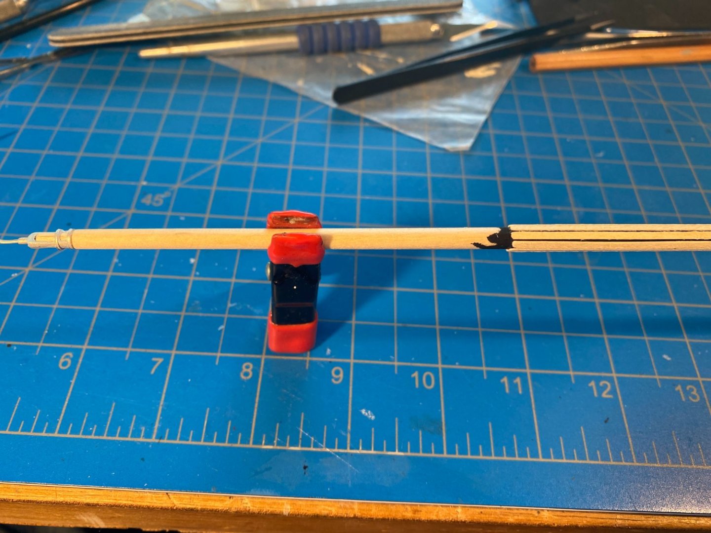
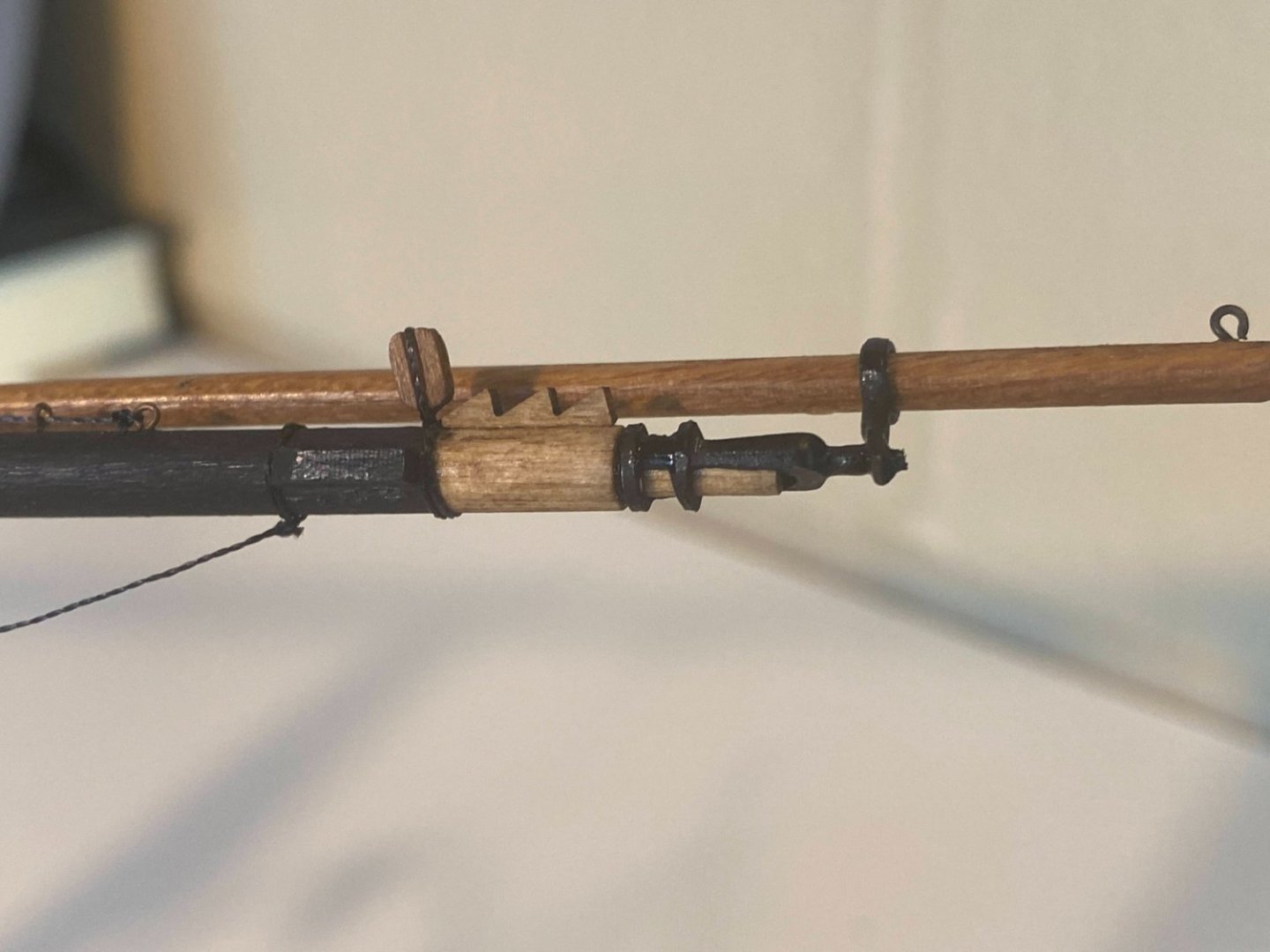
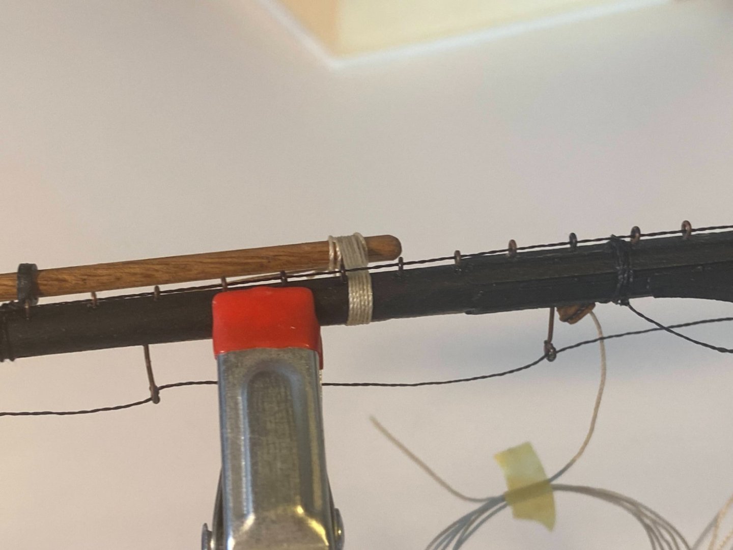
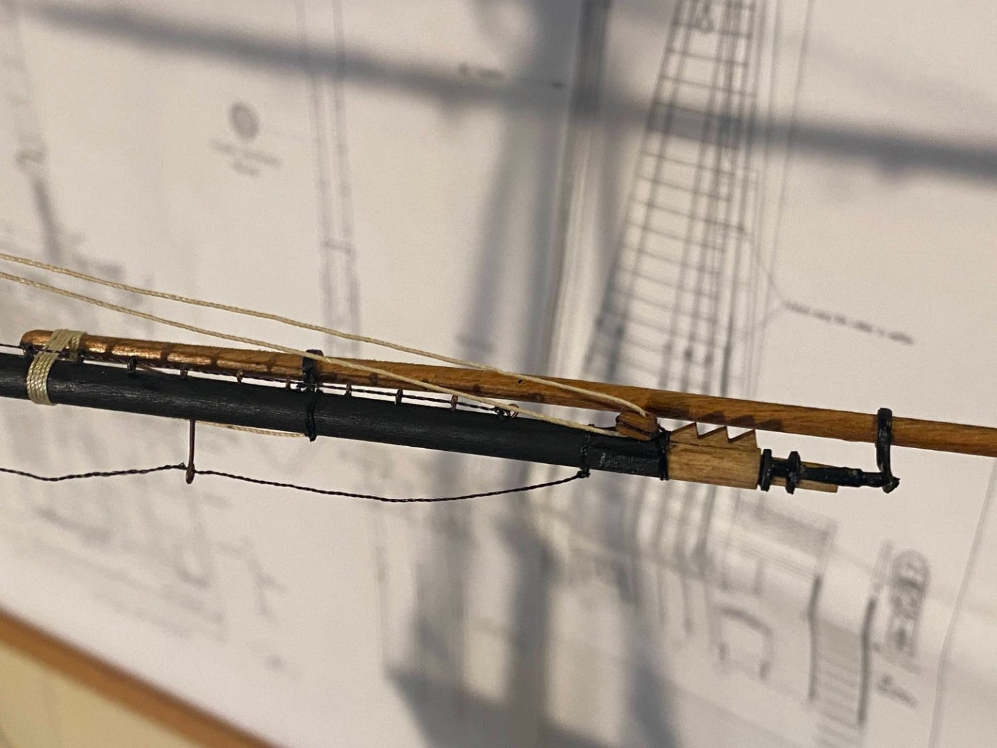
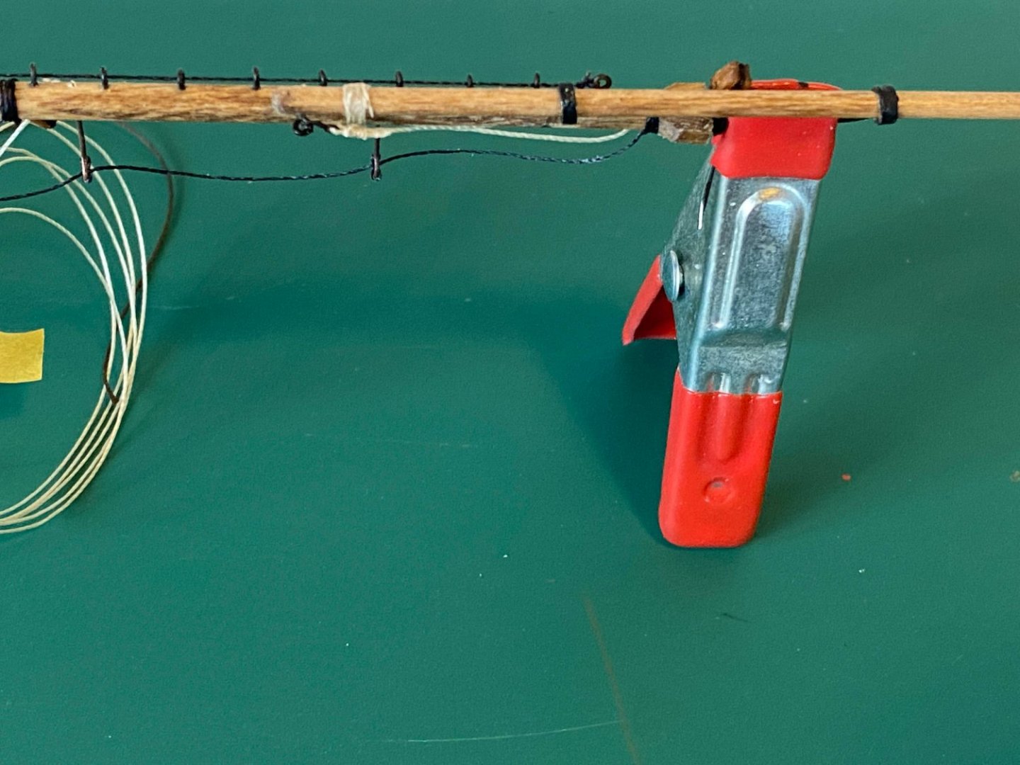
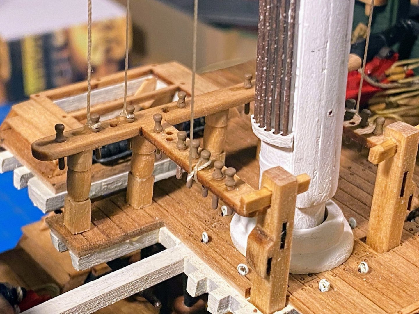
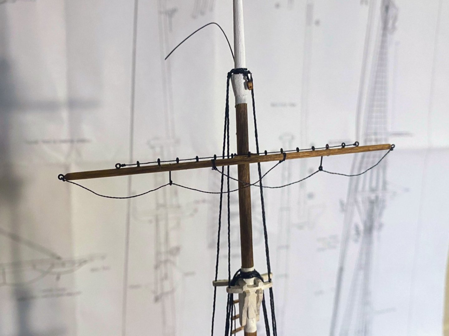
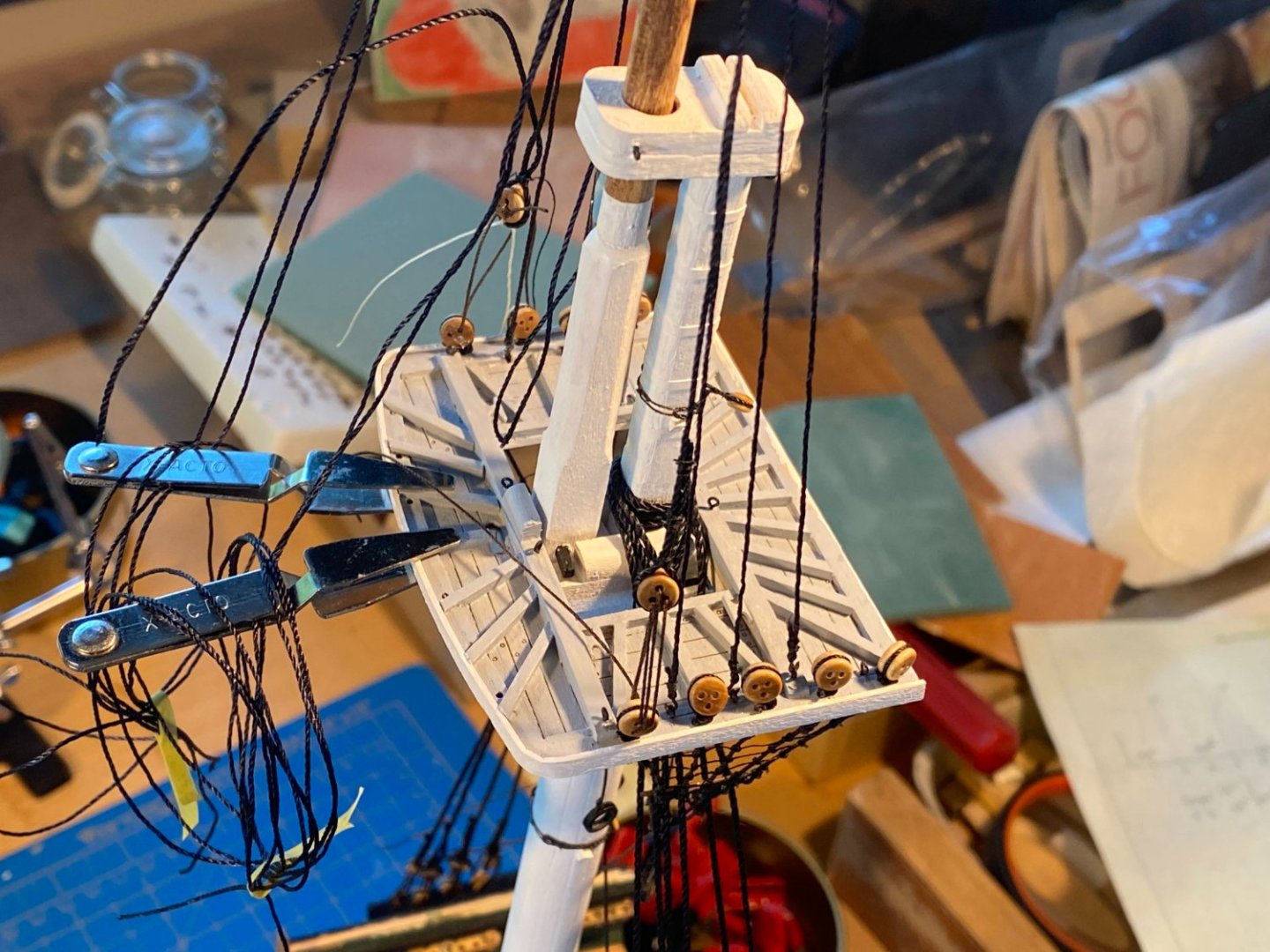
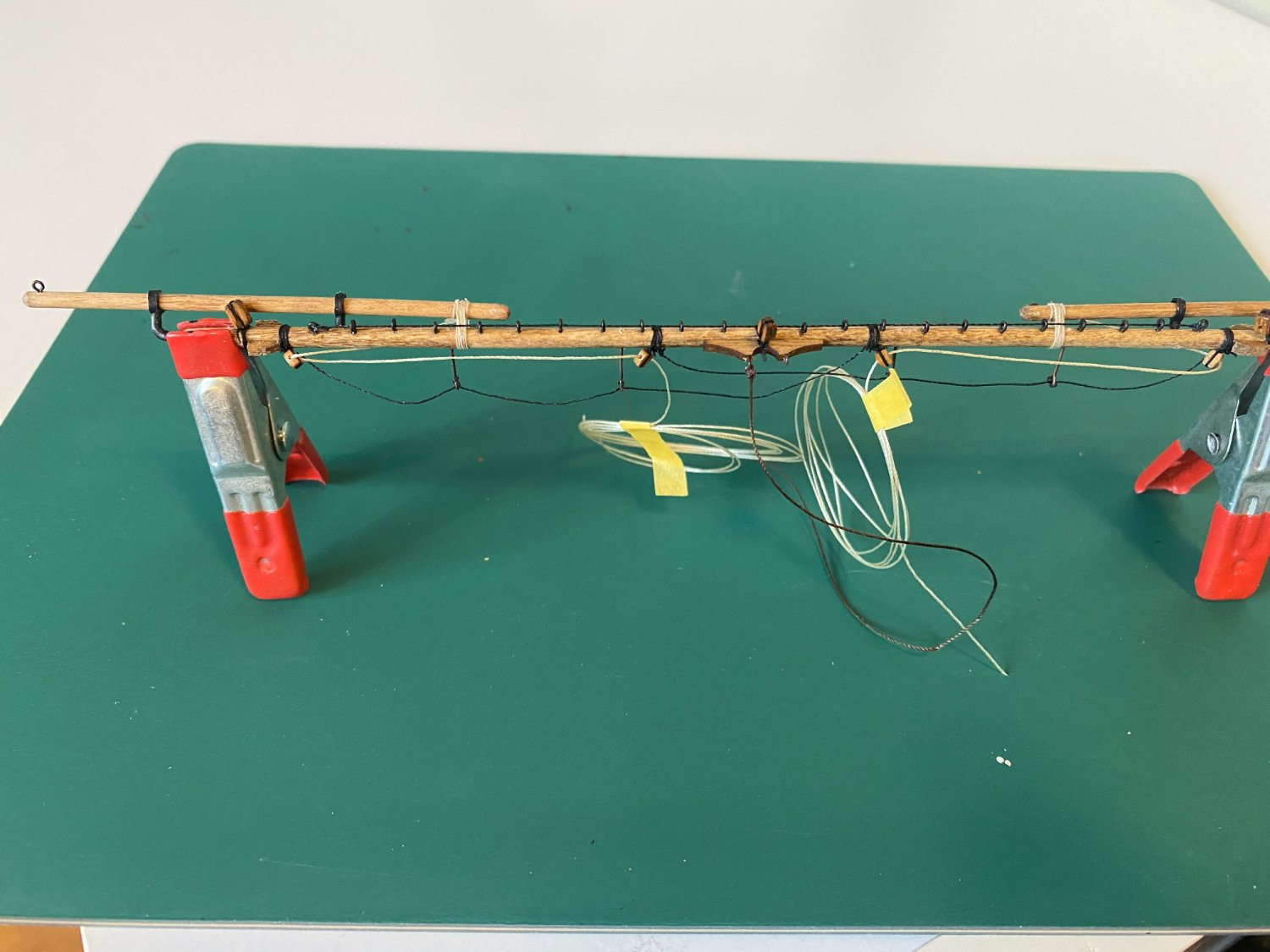
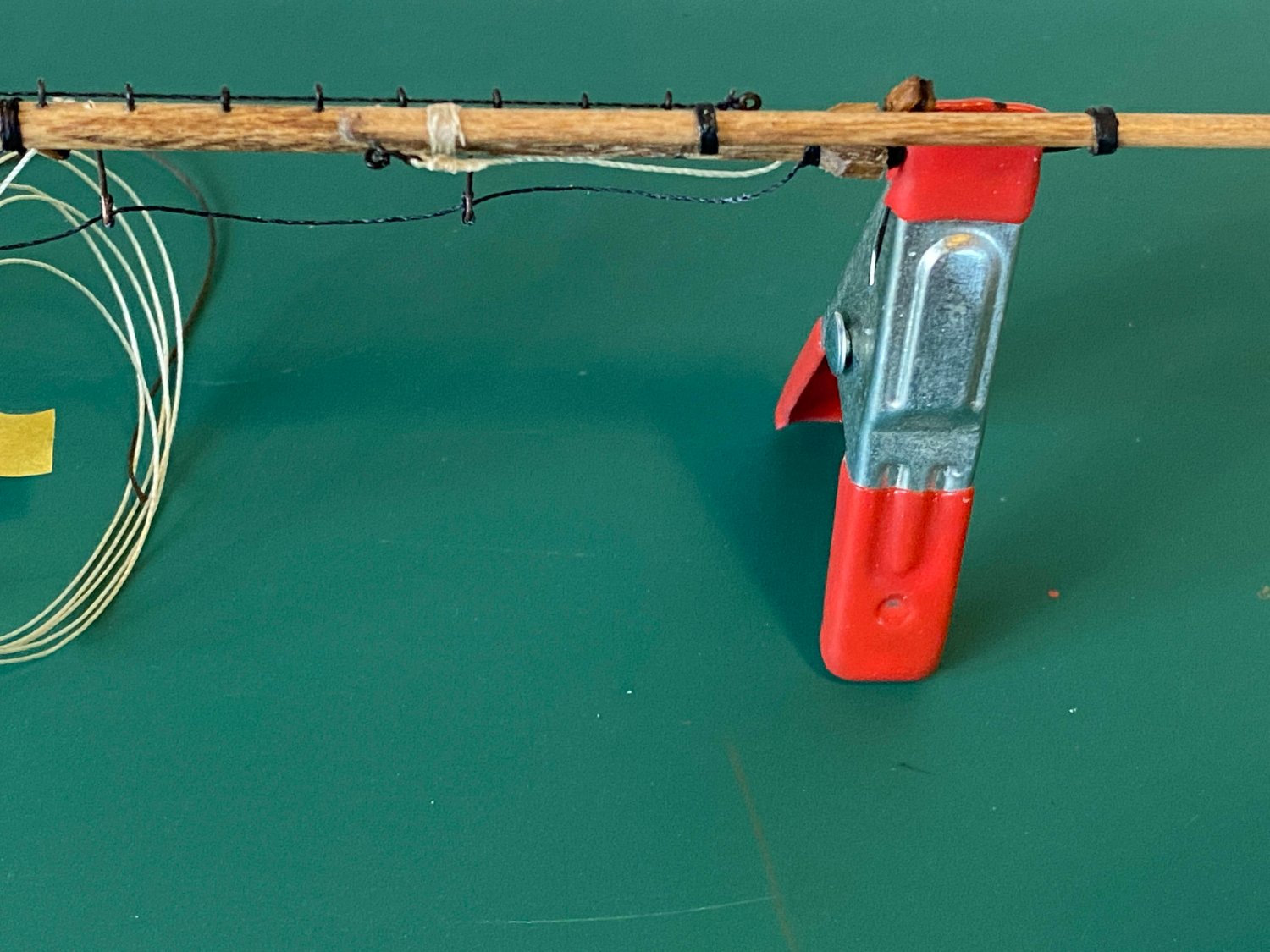
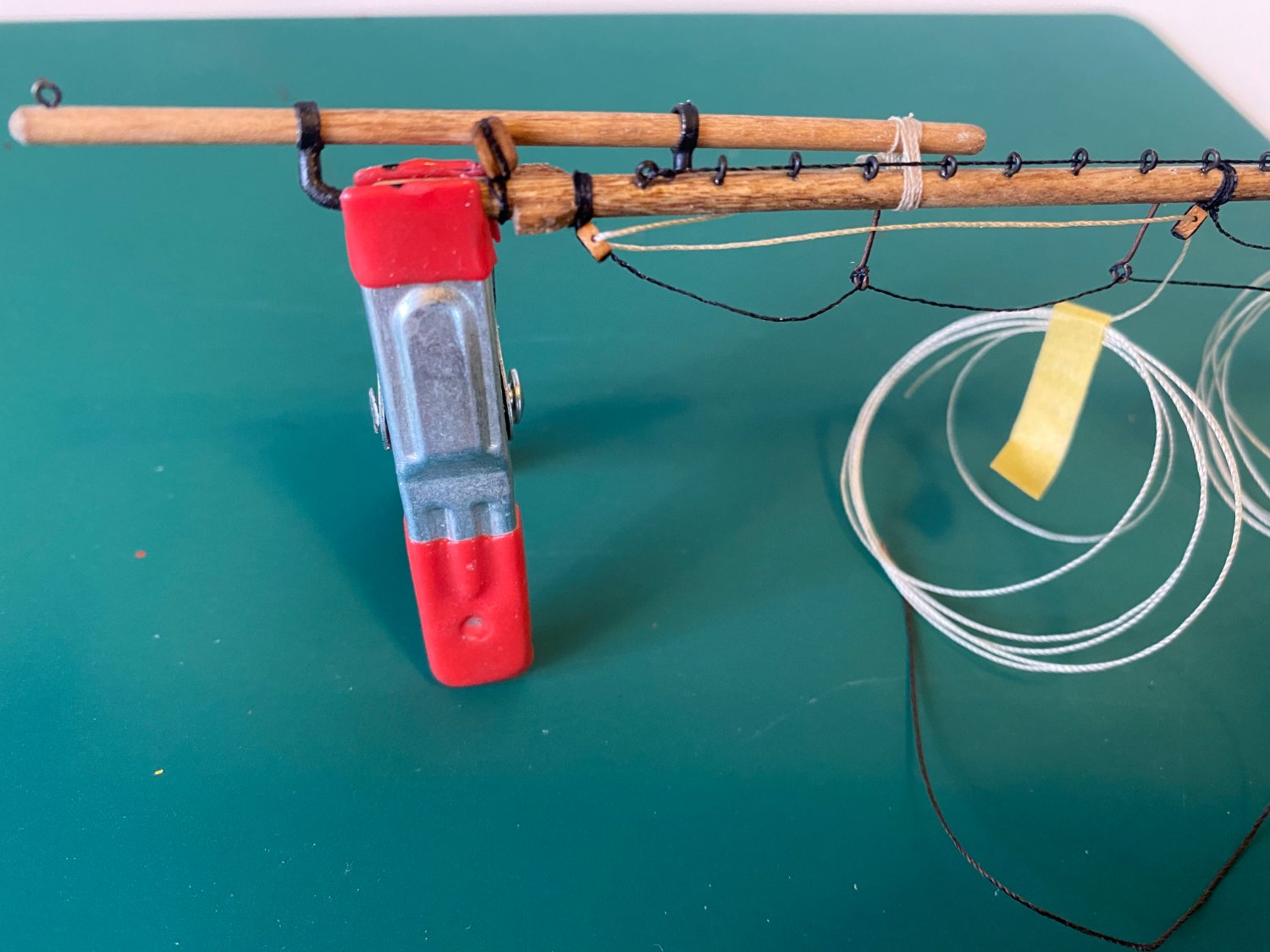
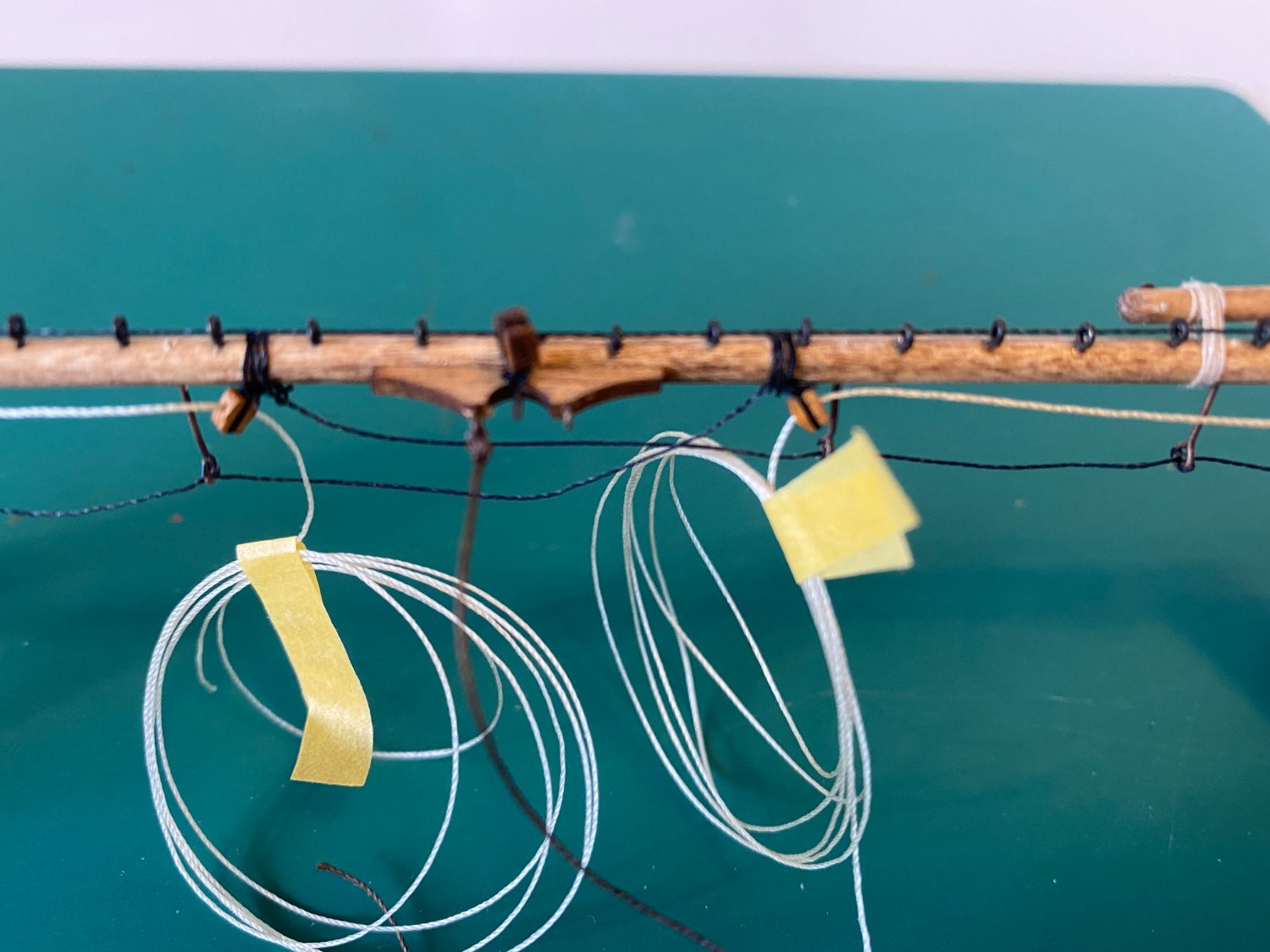
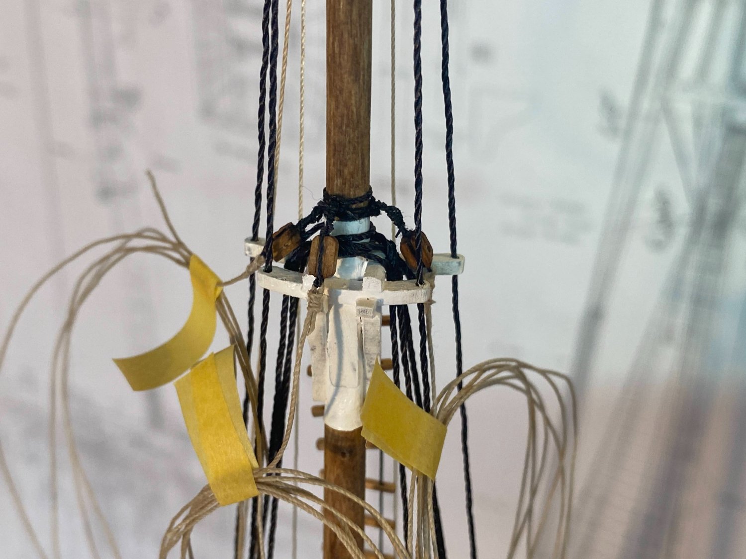
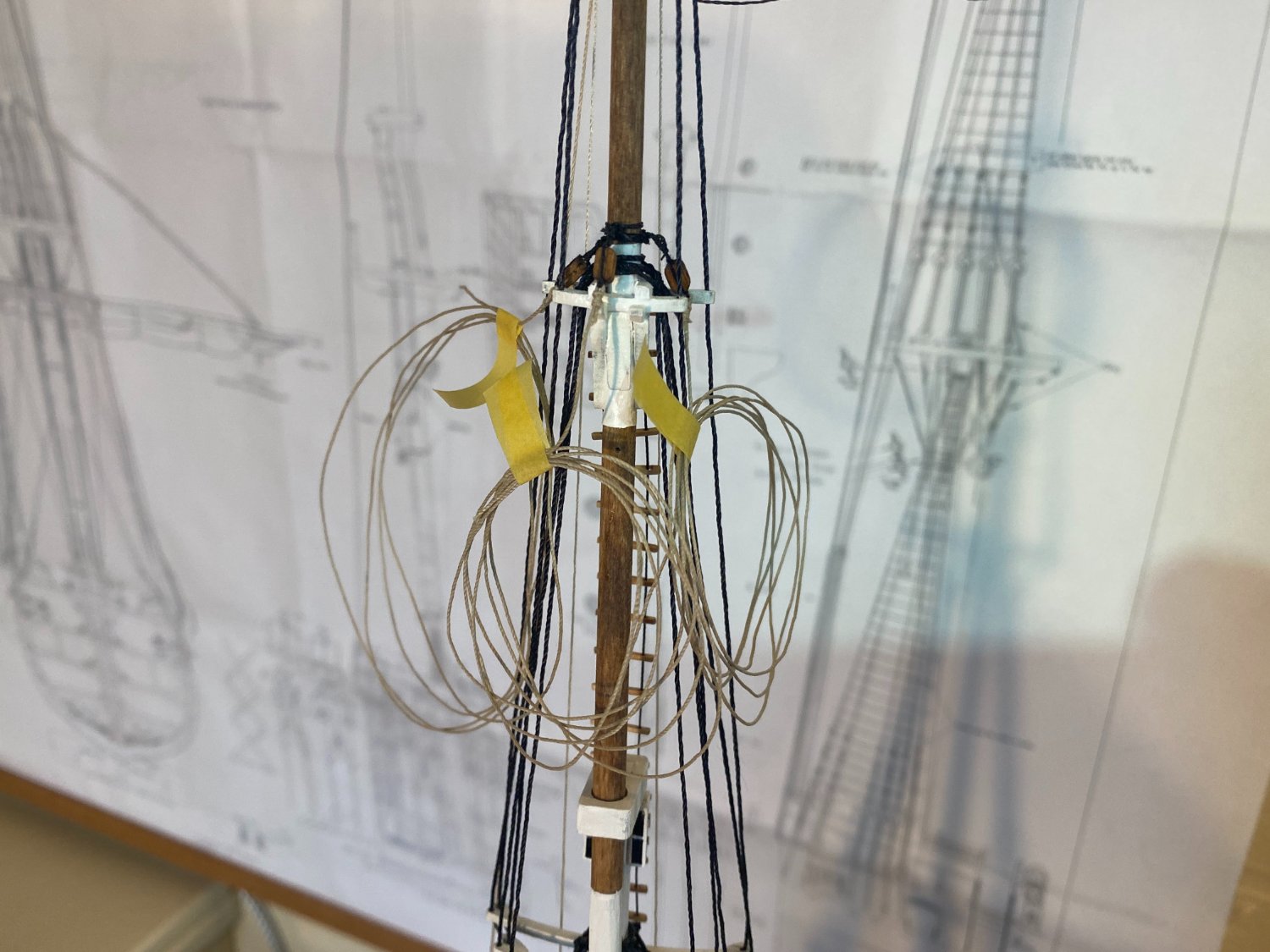
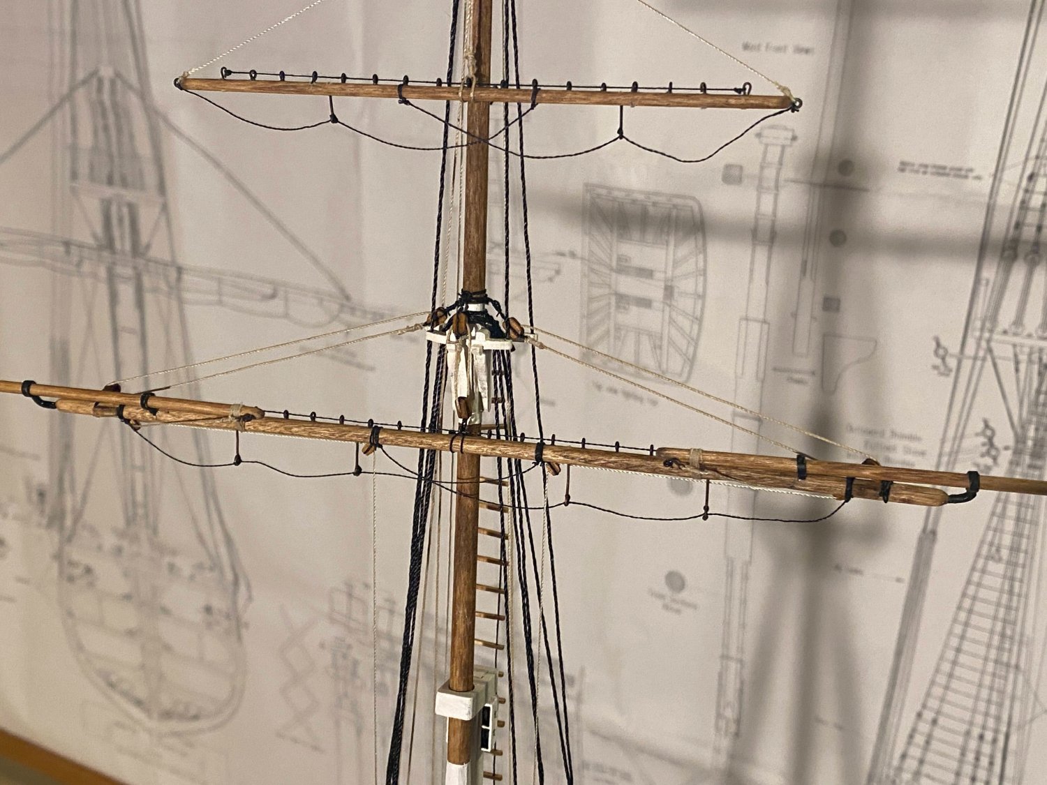
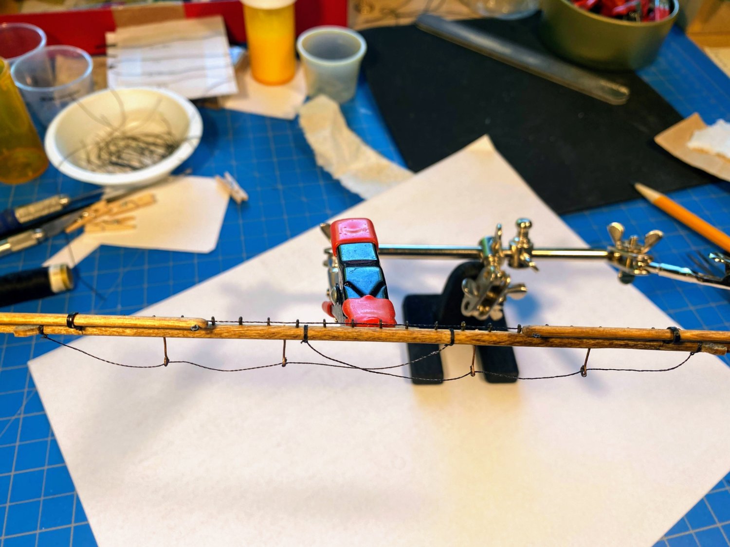
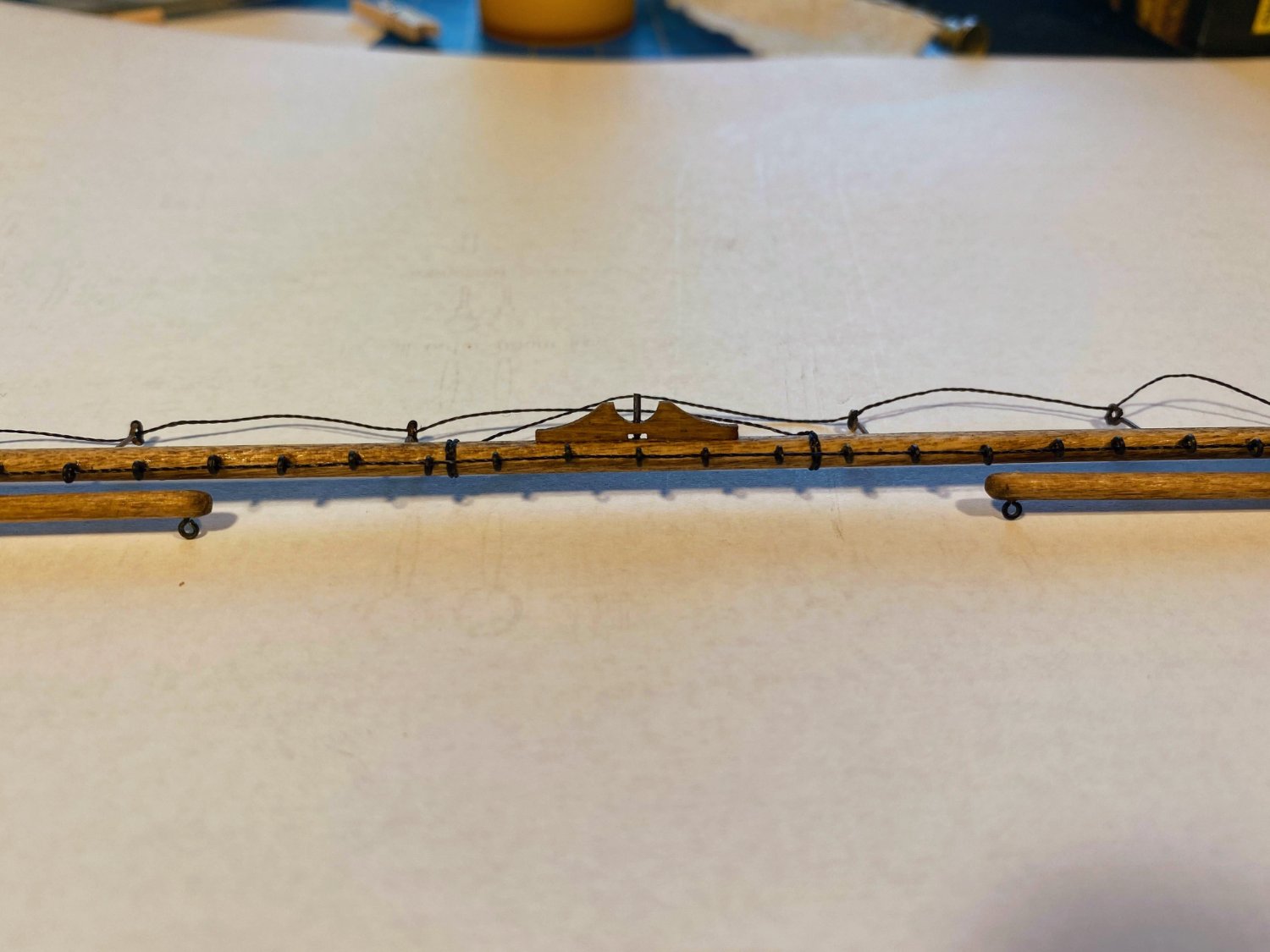
I ended my last post saying the topsail yard would be just like the topgallant yard, only bigger. Yes it’s definitely bigger, but there are some differences as well. As mentioned in a post back in August, the lower two yards are supposed to be constructed from two dowels, separated by a square piece to be shaped to an octagon in cross section. Then battens are to be glued to the flat parts of the octagon section. I found it easier to make the entire topsail yard out of a single dowel, tapered at both ends and leaving the center section round, not octagonal. As can kind of be seen in the picture below, I painted the middle section black before attaching the battens, because the latter fit so closely together I wasn’t sure I could get black paint into the tiny gaps between them. Eventually almost the entire yard is painted black, unlike the yards above which are entirely stained. Studding sail booms: The end guards and end guard rings (terms used in the instructions but not the plans) are two pieces at each end. Both pieces need to be trimmed after gluing together. The end guard is basically a cage that is slipped onto the end of the yard. Rather than taper the yard ends enough to allow that to happen, I tapered them enough to be flush with the outside of the cage/guard, then cut a smaller round section just thin and long enough to fit inside, as can be seen in the picture above. I think the assembly would have looked better if the guard rings had been cast the same as the topgallant yard rings and if the guards had a hole in them through which the stem of the ring would pass, into a hole drilled into the end of the studding sail booms. This yard, and this yard alone, has what is identified as a “coxcomb” glued to the top of the yard, about half an inch in from each end. I don’t know what a coxcomb is or what the other yards don’t have them, but here I did as I was told. Consistent with everything else about this yard, the plans show the footropes running through stanchions that are somewhat longer than those found on the upper two yards. That doesn’t make sense in my mind, as the men who stood on this yard’s footropes weren’t any taller than the men who stood on the footropes higher up. I made these stanchions the same length as those above. As is discussed in further detail below, the topsail yard is supposed to have two halyards, each one leading to either side of the hull, not just a single halyard leading to the starboard side as is the case with the royal and topgallant yard halyards. The locating pin shown below is dry fit and was replaced with a shorter one before installation on the mast. Halyard(s): I viewed the plans as showing a two-ended halyard wrapped around the mast at its midpoint. Seemed pretty obvious to me that running rigging wrapped around a mast wasn’t going to “run” very well. Reading the instructions, what’s contemplated is two halyards, each ending with a clove hitch around the mast. But after leaving the mast, each halyard passes through a double block on the yard, then passes over the top of the forward cross tree, then aft to a single block attached to either side of the mast, then down to the jig which secures it to the hull. How this running rigging is supposed to “run”, and change direction by 90°, when it passes over the edge of the cross tree under tension, is beyond me. So since I was going to ignore both the plans and instructions to remedy that problem anyway, I decided to turn it into a double ended halyard (by hanging a single block on the front of the mast). After passing through the double block on the yard, each halyard runs below the crosstrees and through a single block hanging below and between the middle and aft crosstrees. Finally and a little late now, I wish I had made the halyard jigs shorter. The yards are displayed in their raised position, which would mean that most of the line in each jig would be pulled in and the two ends of the jigs would be close together. As rigged (which is consistent with the plans), to bring the yards down to their lowered positions (shown faintly on the plans as an alternative), the upper ends of the jigs would end up tucked up close beneath the fighting top. I doubt that would be the case on the real ship.


- 163 replies
-
- 5
-
-
- Model Shipways
- Constitution
- (and 2 more)
-
Thank you Brian and Tom. Repeatedly throughout this build I've thought how grateful I am that I'm building a cross section and not the full Connie. I don't think I'd have the patience to do what I'm doing three times over. 😱
- 163 replies
-
- 2
-
-
- Model Shipways
- Constitution
- (and 2 more)
-
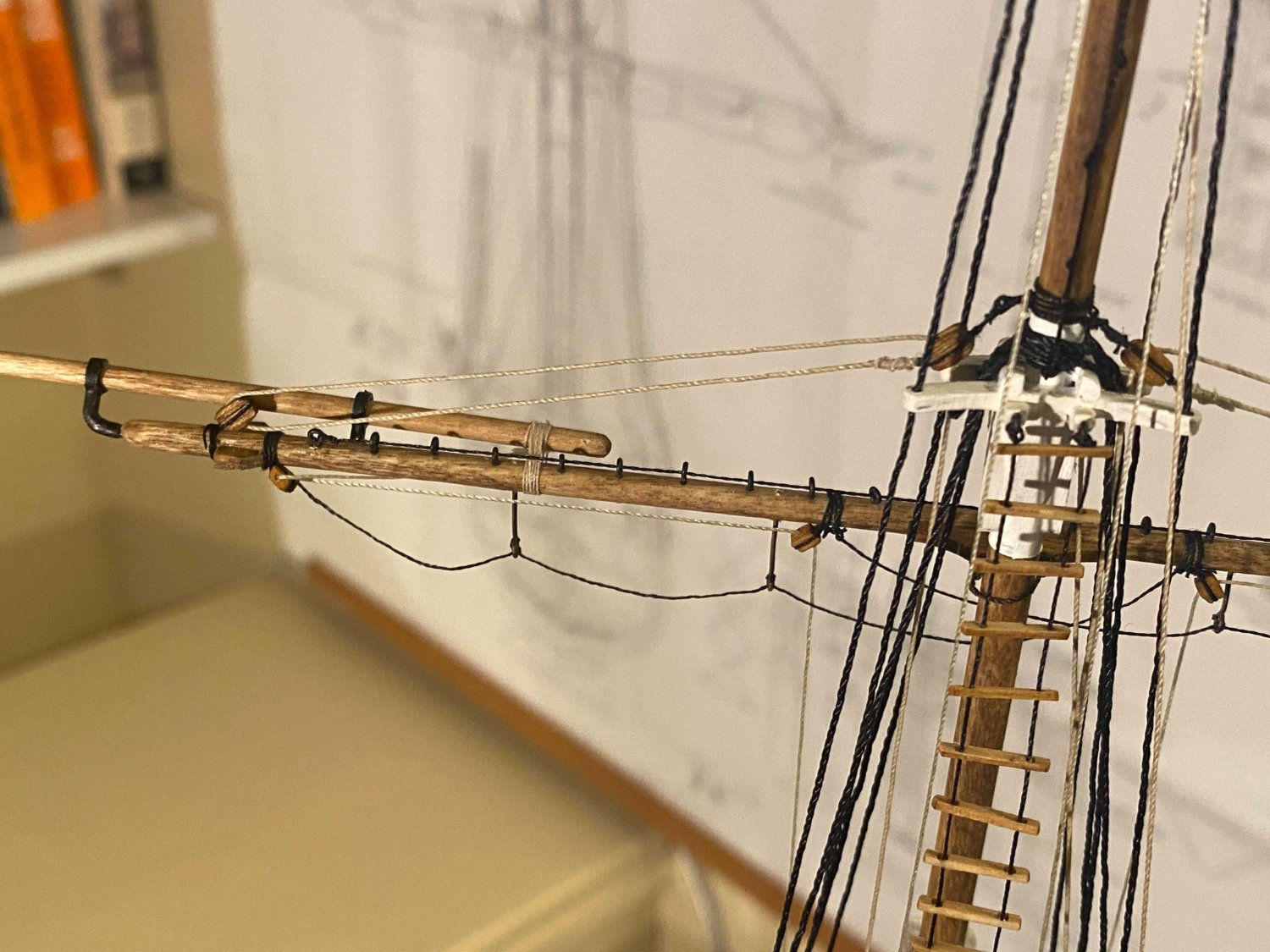
Almost a month since my last progress posting. Where did the time go! Installing and rigging the topgallant yard was almost the same as the royal yard, but with the addition of the studding sail boom halyards and additional purchase on the lifts and boom halyard. First I needed to seize a number of blocks in place. There is a single block seized on the upper side of the yard outside each pair of chocks (for a total of two, not four as stated in the instructions), for the lifts. Then for the studding boom halyards, a single block on the underside just inside each pair chocks, and a single block on the underside about 5/8” out from each side of the center of the yard. Finally for the topgallant halyard, a single block is seized to a sling which wraps around the middle of the yard. The instructions show the halyard seized to this block, needing a double block above it on the mast, but the plans (which I followed) show the halyard seized to the mast block, resulting in a tackle with two single blocks. Hooks need to be seized on the end of two long pieces of thread which will be the studding boom halyards. The hooks are attached to the eyebolts previously installed at the inner end of each boom, and the thread then gets led through the lower blocks near each end of the yard, then through the blocks near the center of the yard, and coiled for now. Finally one end of the parrel can be tied to one of the eyebolts sticking out of the back of the yard yoke. A pair of single blocks for the lifts need to be seized to each side of the mast just above the shroud loops wrapping around the mast, above the topgallant cross trees. A long piece of thread needs to be seized to each such block. The yard halyard is seized to a block, which in turn is supposed to be attached to a sling which secures it to the forward side of the mast, but somehow mine turned out to be just another seizing. As mentioned above, I used a single block here. The lifts and halyard can be coiled to await attachment of the yard to the mast. Next was gluing the yard to the mast, using the location pin at the back of the yard and a hole I had previously drilled in the front of the mast. I then secured the loose end of the parrel to the open eyebolt in the yoke. Then came the fun of releasing the coils of rope, one by one, leading the line down through the standing rigging to belaying pins at deck level. . . a relatively easy step which leads to satisfyingly significant progress. Comments on doing this: The royal yard lifts ran easily from the blocks on either side of the mast, behind the topgallant and topsail crosstrees, through the aft end of the open spaces in the fighting top, behind the futtock shrouds, without interference all the way down to the aft side of the fife rail. Here I made a mistake, belaying the port lift line to the second pin in from the end rather than the third pin in. As discussed below, I didn’t not correct the error. The royal yard halyard ran from its block on the mast, around the starboard side of the mast, aft of both sets of cross trees, aft and outside the fighting top. It then went down to where it was seized to the double block which formed part of the jig tackle, the other end of which was hooked to the outer eyebolt attached to the aft end of the starboard channel. The topgallant studding sail boom halyards ran from their blocks on the yard, down just outside the forward topsail crosstrees, through the middle of the spaces on either side of the fighting top, ahead of the futtock shrouds, and down to the fore and aft parts of the fife rail. The topgallant lifts ran from their blocks on either side of the mast, behind the topsail crosstrees, through the aft end of the open spaces in the fighting top and inside the royal lifts, and on down to the aft side of the fife rail where they were belayed to the pins just inside where the royal lifts were belays. The fact that the lifts on the port side were belayed one pin farther out than the lifts on the starboard side caused no problems, and I decided this was an error not worth correcting. The topgallant yard halyard ran parallel to the royal yard halyard down to its jig tackle. In hooking the tackle to its eyebolt in the starboard channel, the main part of this tackle ran between the main part of the royal tackle and the tail end of the royal tackle belayed inside the bulwark. On to the topsail yard. More of the same . . . only bigger.


- 163 replies
-
- 6
-
-
- Model Shipways
- Constitution
- (and 2 more)
-
Welcome Brian and thank you. I hope you find my log to be helpful. Although I have found this build to be more challenging than expected, it's been really rewarding, and I have enjoyed it immensely. I hope you have a similar experience.
- 163 replies
-
- 1
-
-
- Model Shipways
- Constitution
- (and 2 more)
-
Thanks for the kind words Tim. Too often I look at a close up photo of my work and see nothing but flaws. I guess we all have some tendency to be hard on ourselves.😀
-
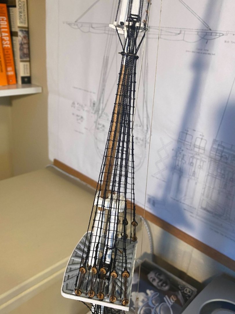
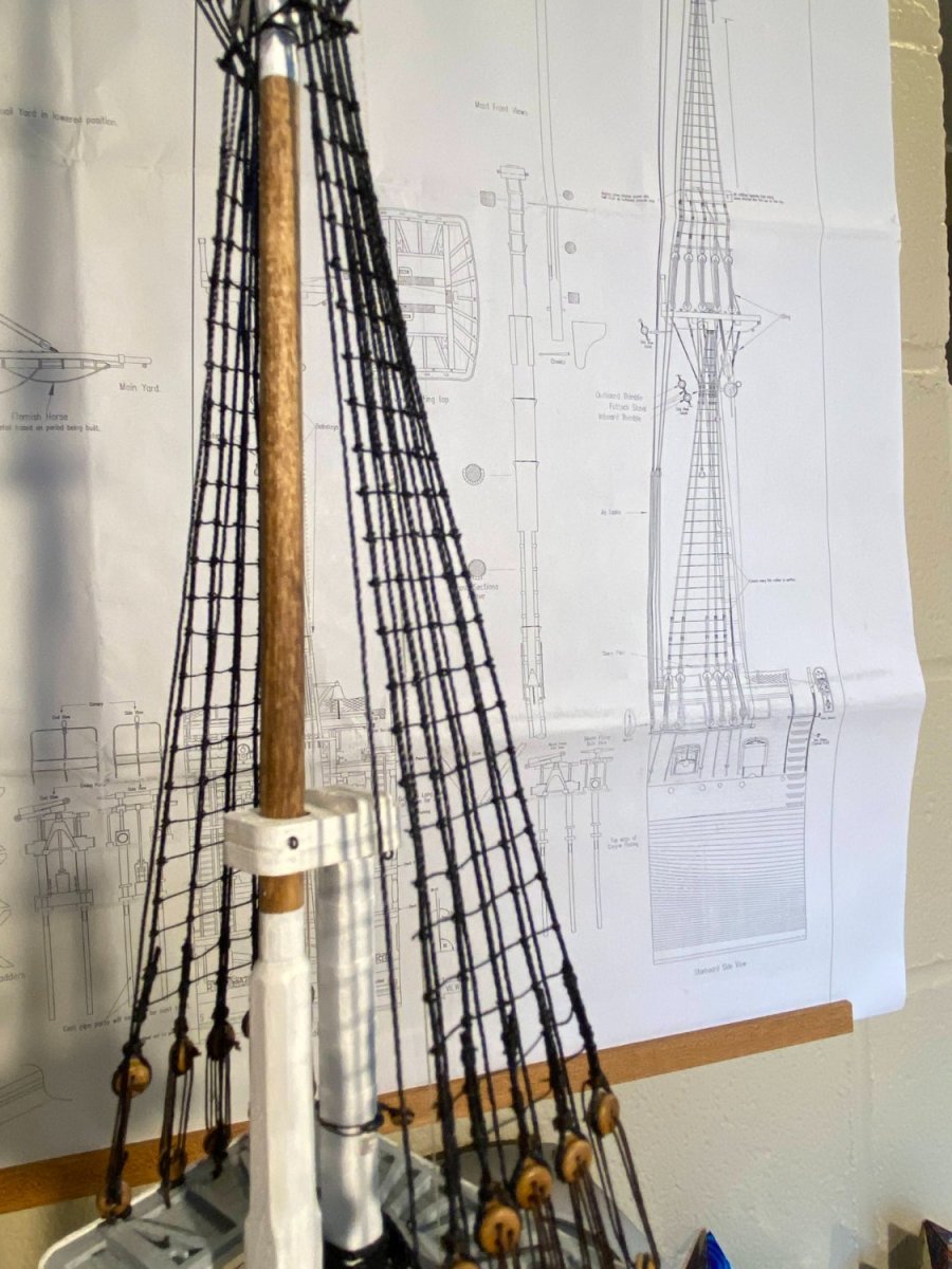
I have finished the ratlines on the topmast shrouds. I still need to add sheer poles above the deadeyes. As I neared the top, the challenge was threading and tying the ratlines where the shrouds were so close together. On the final one at the top, I omitted the clove hitches on the shrouds on either side of the middle one, to avoid ending up with nothing more than shoulder to shoulder knots. There should probably be one more ratline in the gap between the top one and the futtock stave, but as it is things are awfully crowded there. I’m hoping the lower ratlines are a little easier to do than these were. No second set of shrouds immediately behind the ones with the ratlines, and a little more space to work with at the top.


- 163 replies
-
- 1
-
-
- Model Shipways
- Constitution
- (and 2 more)
-
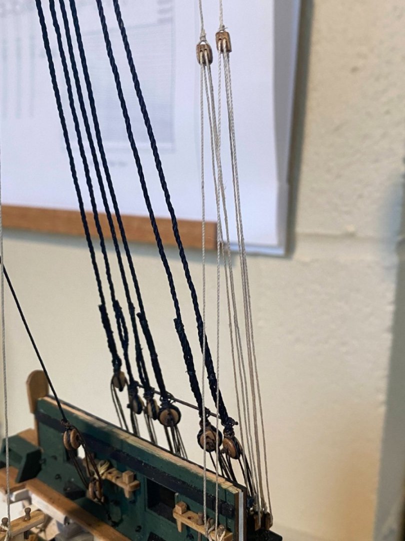
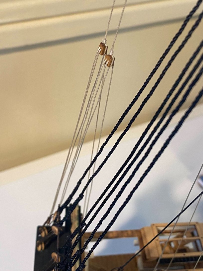
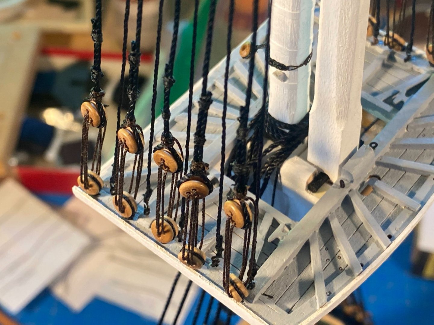
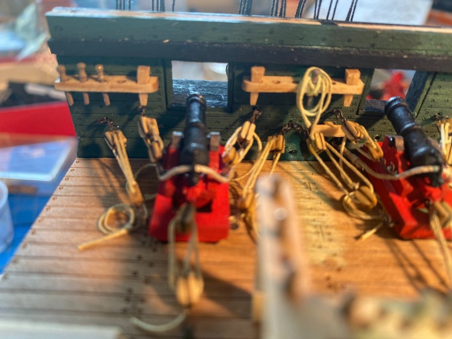
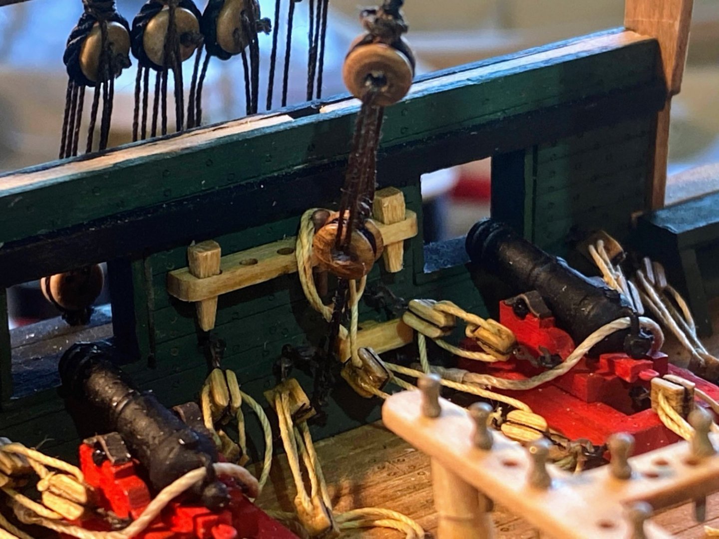
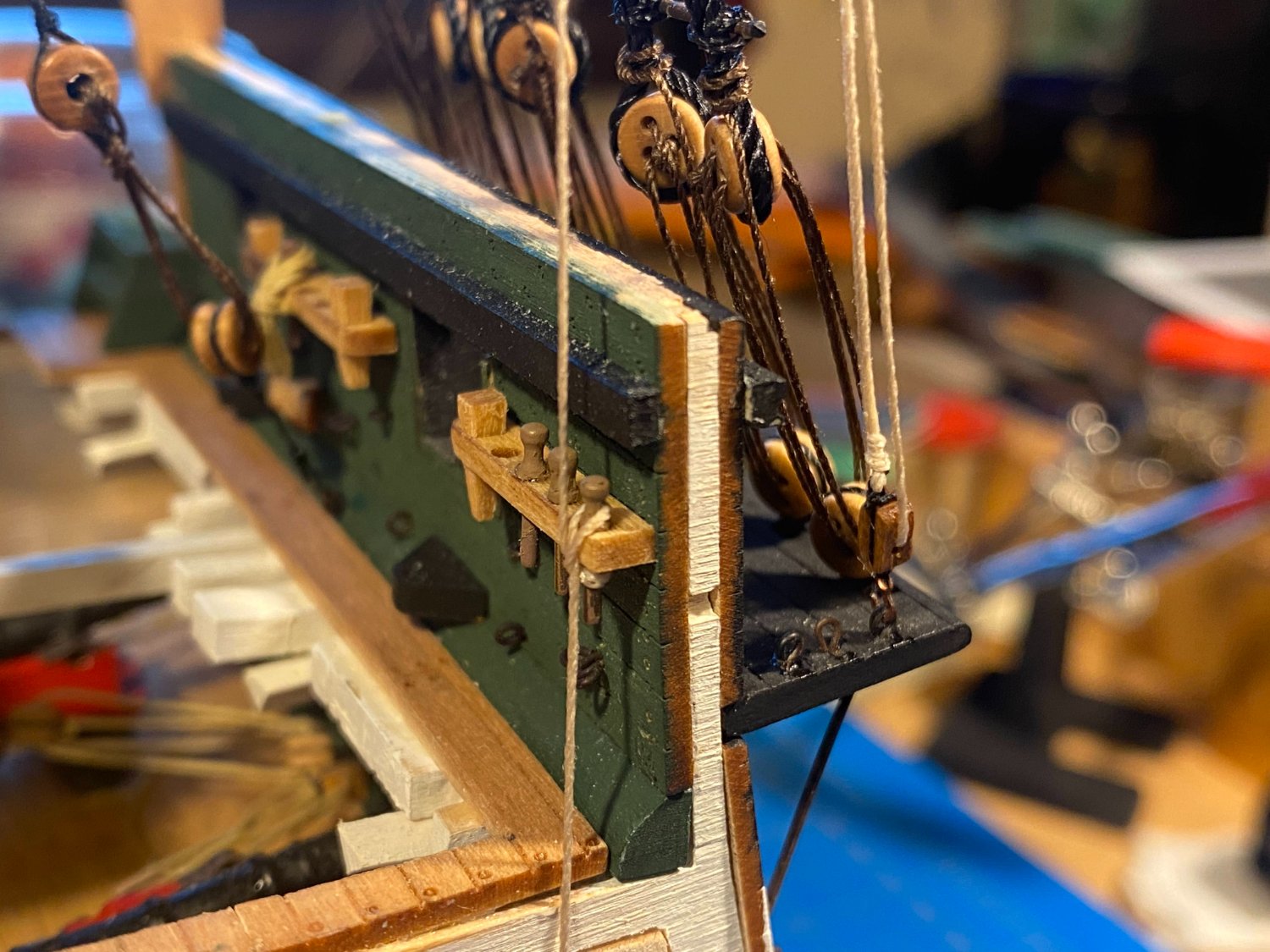
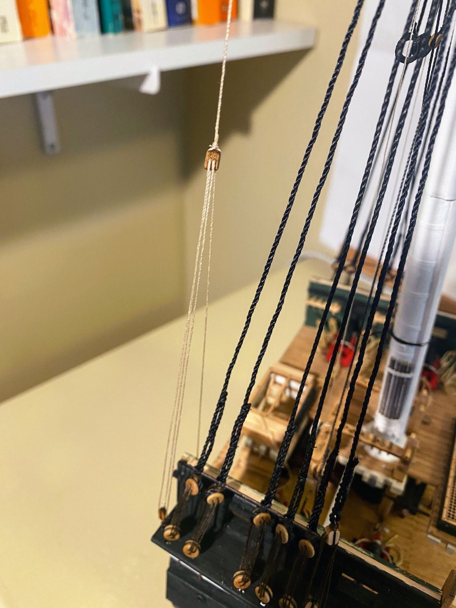
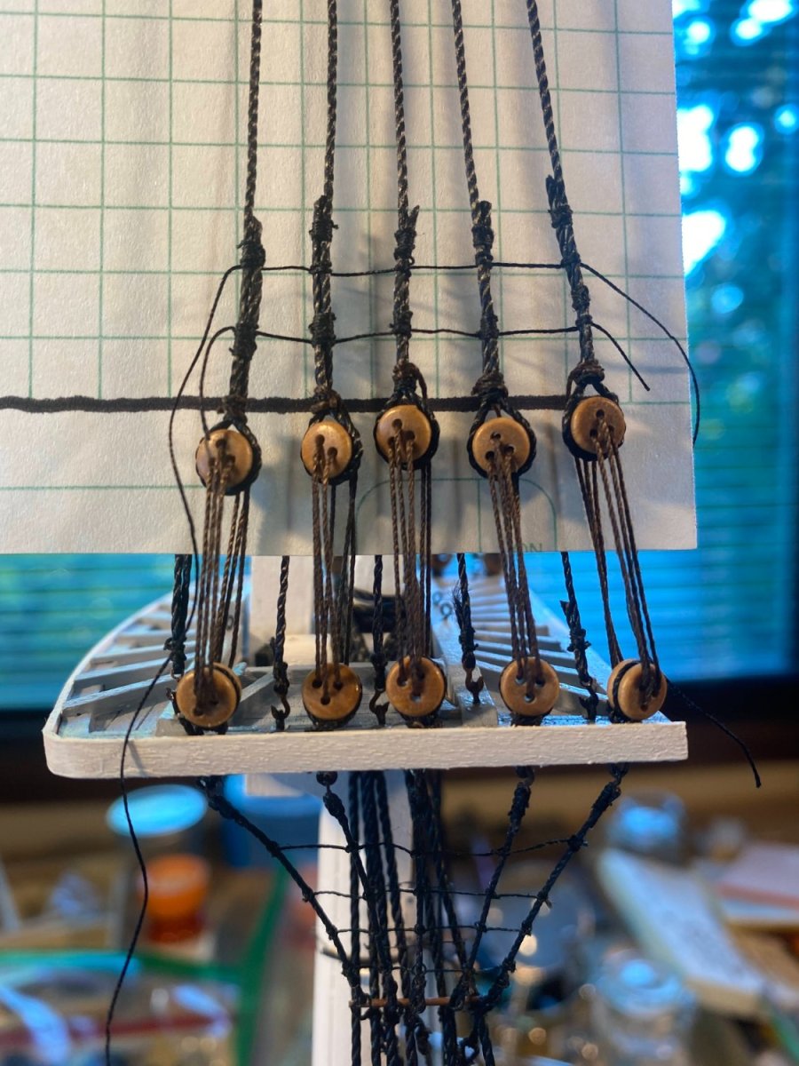
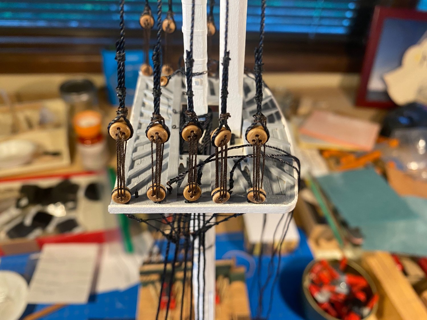
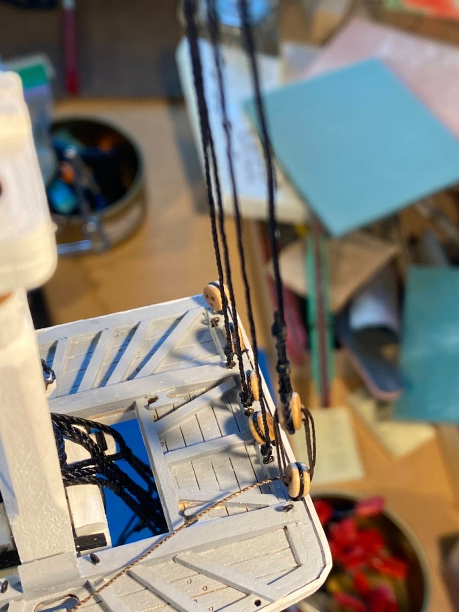
Rigging and installing the royal yard was simple and straightforward. I generally enjoy working on running rigging more than standing rigging. As suggested in the instructions, I installed the rigging on the yard before gluing the yard to the mast. The lifts run from each end of the yard up to small blocks tied to either side of the mast at the circular shoulder, then down to the pin rail where they are belayed. The halyard is looped through the yoke and around the middle of the yard, up to the remaining small block on the mast, and down the starboard side to a block and tackle to be hooked onto an eyebolt installed at the aft end of the starboard channel. Some comments on the halyards: The royal, topgallant and topsail yard halyards all end similarly, except that the topsail yard halyard has two ends, the other end attaching to a similar arrangement on the port side. The instructions refer to the halyard block and tackles as “jig tackles”. The instructions are a little confusing here. Consecutive paragraphs, both beginning with drilling holes and installing three eyebolts in the aft end of the starboard channel (one in the port channel), then going on to describe partially overlapping, partially different, parts of the royal yards running rigging. Each jig tackle is the same. A hook is stropped to one end of a single block (incorrectly referred to as a double block in the instructions), and the jig tackle line is seized to the other end of the block. The line then runs up to a double block seized to the end of the halyard, about 5 inches above the channel. The line runs through that double block, down to the block with the hook, back up to the double block, and then down to the pin rail on the starboard inner bulwark, where it is belayed. Finally, the instructions say to use beige thread for the parallel, but I don’t think of that as running rigging. I used dark brown thread, the same thread I used to lash shroud deadeyes together (“adjustable standing rigging”). Here are more pictures. I recently came across a discussion on these boards about belaying (which I can't find now). A convincing argument is made that repeated figure 8 wraps around the pin are not necessary and not historically accurate. Rather, as I have done in the photos above, make one loop around the bottom of the pin under the fife rail, and a second one above, the latter being looped under itself, or belayed. On a real ship, the line can be quickly unbelayed if adjustments need to be made in a hurry, and on a model this two loop belay is quick and easy to do. Hopefully the tails I left in the final photo above will be hidden by the coils that will be installed later.


- 163 replies
-
- 3
-
-
- Model Shipways
- Constitution
- (and 2 more)
-
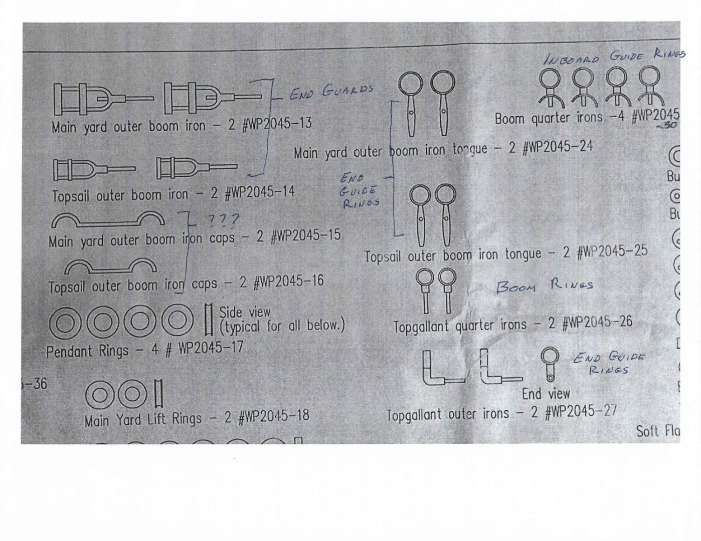
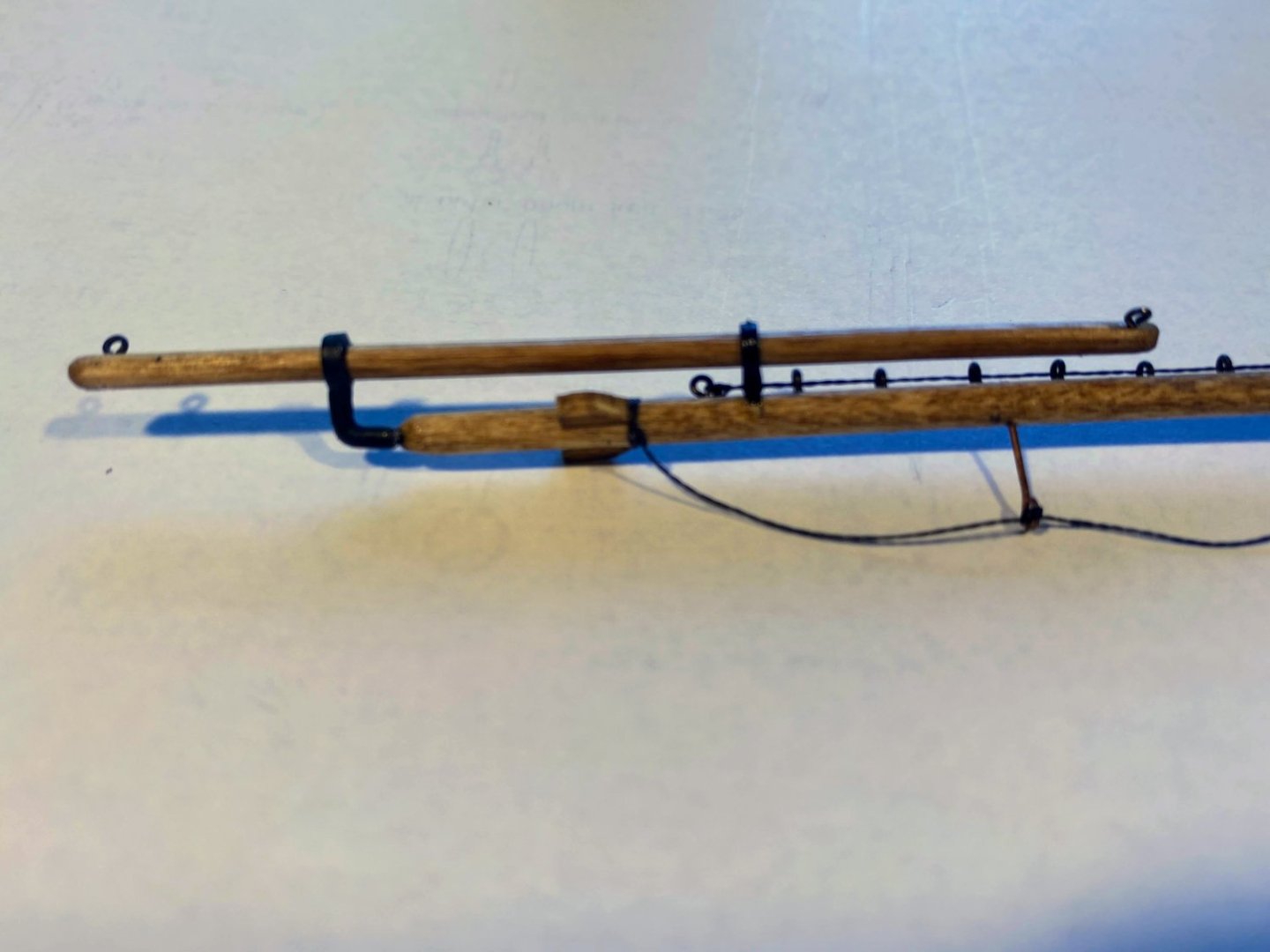
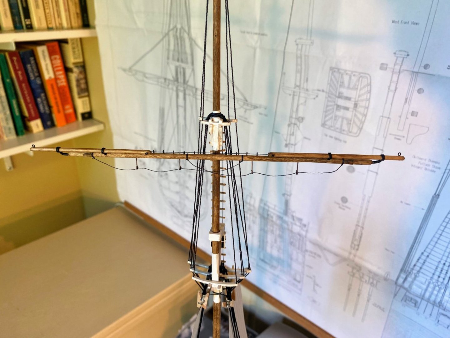
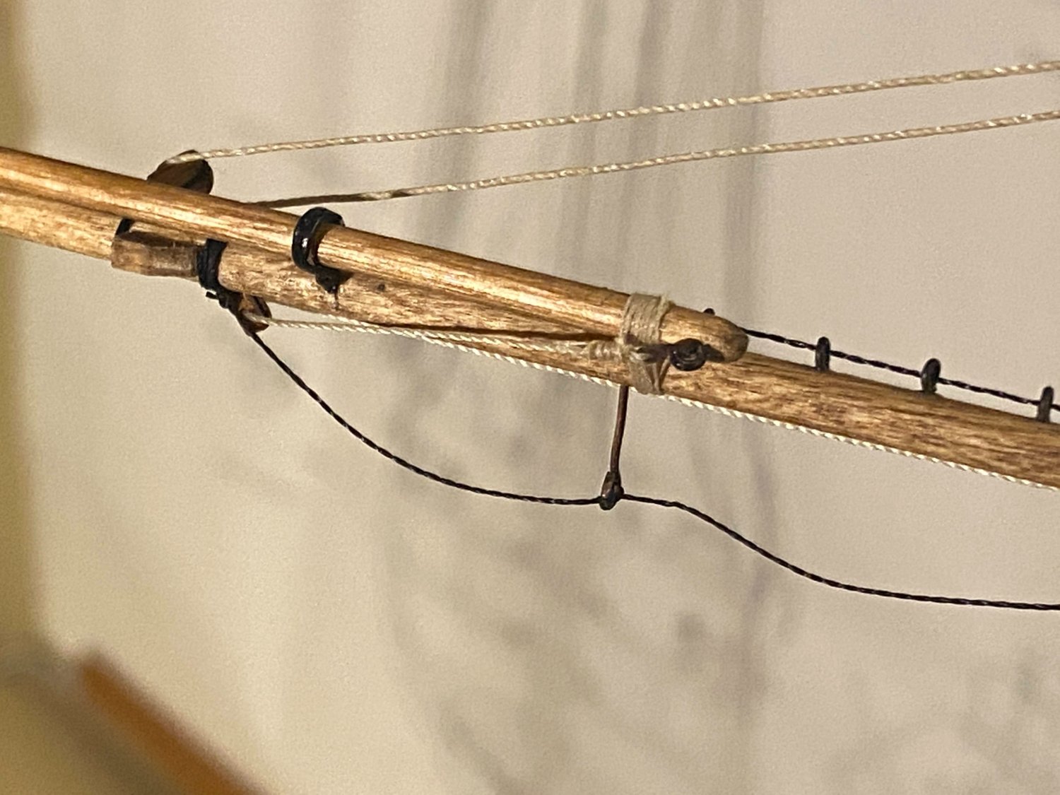
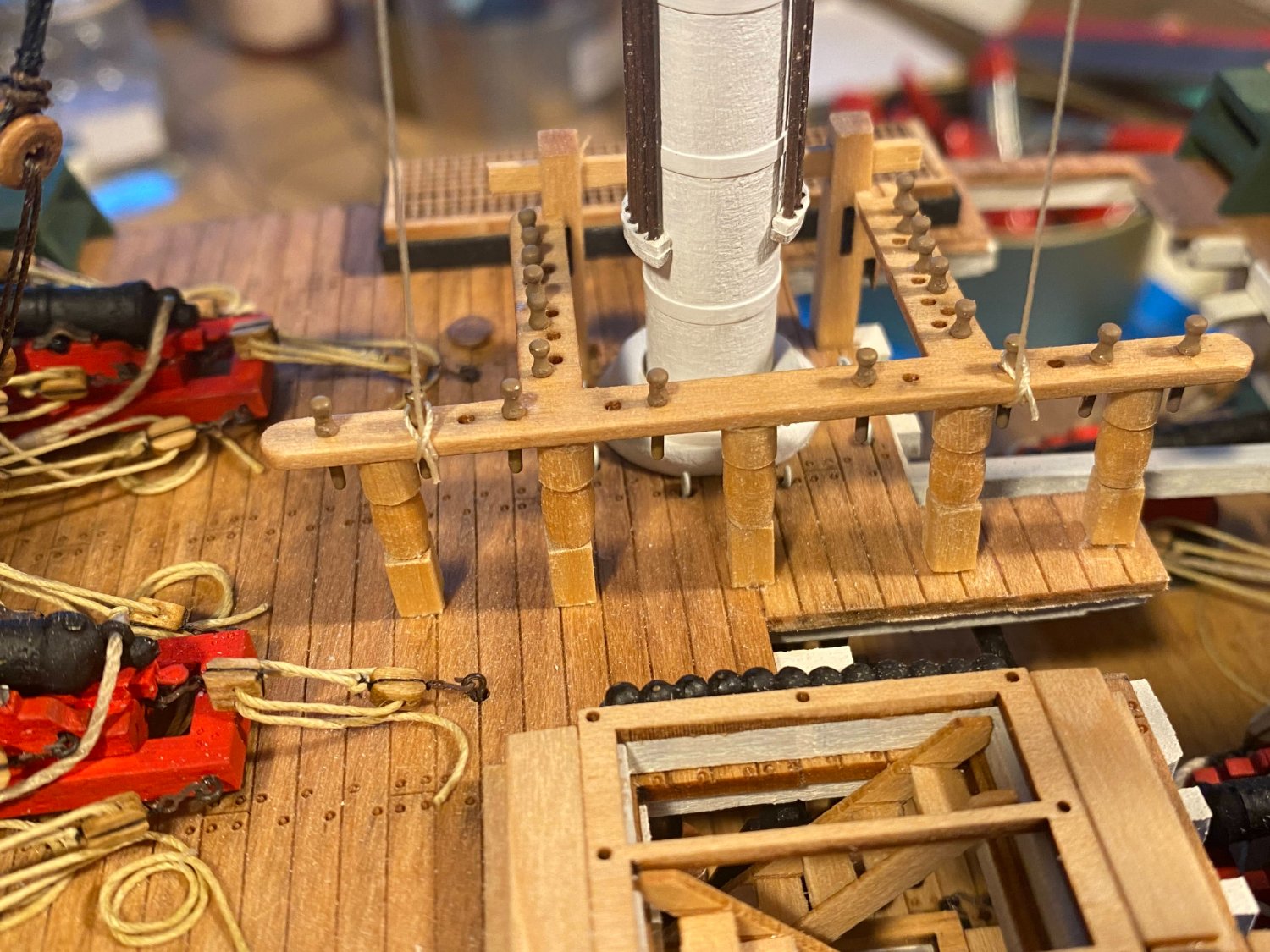
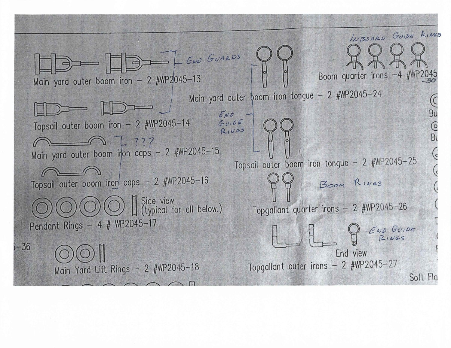
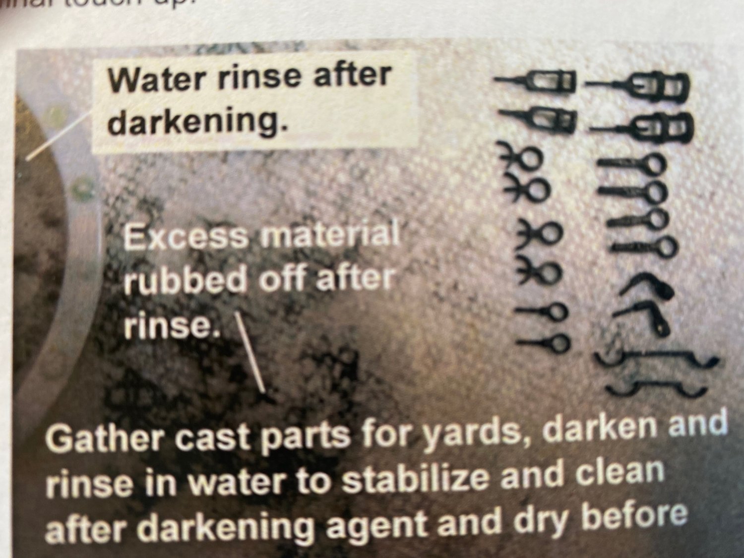
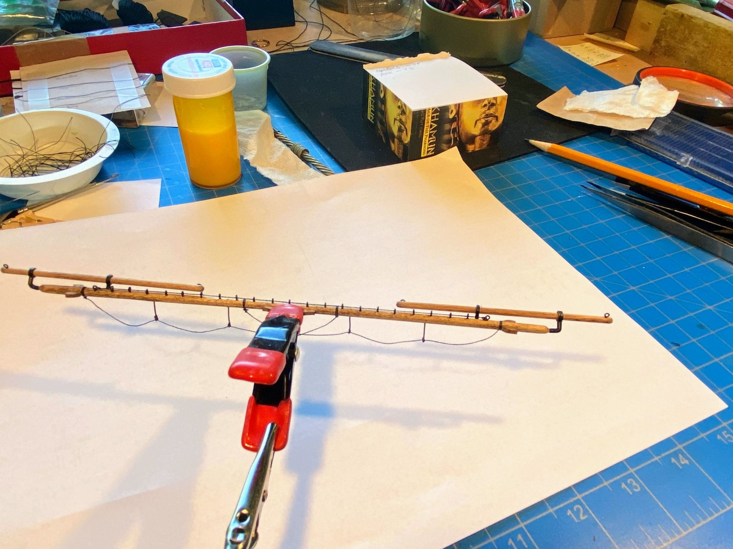
Thanks for the comment Bob, and thanks to all who have added their "likes". Working my way down the mast, the topgallant yard is next. I didn’t get much in the way of progress pictures, but there are a number of things to talk about. This yard and the ones below it have studding sail booms, which are used to extend additional sails out beyond the yards themselves. These booms require hardware (“iron work” in the words of the instructions), and the instructions are a real problem here. They start with a picture of the various pieces, saying there are 18 of them when there are actually 20. The picture and the plans show 18, but the plans’ text say that there are a pair of “main yard outer boom iron caps” and a pair of “topsail outer boom iron caps”, which is in fact what is supplied with the kit. Not a big deal since, at least as far as I can tell, none of these 4 boom iron caps are used in this model! I have no idea what they are supposed to be. But far more concerning is the fact that the instructions and the plans inexplicably do not use the same terms to describe these less-than-intuitive parts. The plans show part numbers for these things (#2065 followed by a hyphen and a two digit number), but the instructions do not refer to the part numbers at all. After studying the instructions at length, I think I have figured it out, and in the picture taken of the plans below I have written in the terms used in the instructions. I hope future builders find this helpful. I would add that the instructions say to "darken" these pieces, but I have never found what I use, Darken-It, to work on Britannia metal. I used flat black paint. The lower three yards also have a pair of chocks at the outer ends, and these are laser-cut in small, medium and large pieces. Only problem is that there is only one pair of each size and obviously two pairs are required. Not a big deal as they are easy to cut from the same sheet of wood that the laser cut pieces come from. The instructions don’t mention, but the plans show, that the booms are angled up and out away from the yards at a 45 degree angle. Or perhaps more clearly, looking at a cross section of the yard and boom, with the top of the mast being north and forward being to the east, the booms are to the northeast. Holes need to be drilled in the yard for what the plans call “top gallant quarter irons” (one for each boom), which can be glued in place. Then insert the “topgallant outer irons” in holes drilled into the ends of the yard, but as the instructions appropriately warn, don’t glue until the booms are slid in place and these fittings can be angled in such a way that the booms and the yards all run parallel to each other. As I did with the royal yard, I ran the thread for the foot ropes through some diluted white glue and let it dry before rigging them through the long eyebolts and tying them to the yards. That worked fairly well with the first foot rope on this yard. The second one was an entirely different story. For some reason tying the end of the thread to the boom proved really problematic, and I couldn’t get the clove hitches on the eyebolts to look or act anything like clove hitches. After spending more time on it than I did on the previous three foot ropes combined, I went to tie the remaining end onto the boom and realized that the thread was too short to have any realistic chance of tying a knot. After cussing up a storm (fortunately my wife wasn’t home), I got up from my work bench (the smartest thing I did all day), went outside and took a walk of about a mile, and ate lunch before returning to my work bench. Things went a little more smoothly the second time around, but again it proved to be harder to do than it should have been. Next time I may experiment with going back to merely wetting, stretching and drying the thread before tying it on, then applying diluted white glue with the hope of being able to bend the thread to the desired look and having it stay that way. Enough text . . . here are some pictures. When I took them, I had not yet added the eyebolts to the yoke for the parrell. And here’s the topgallant yard dry fit on the mast. I am going to take a little break with the yards and get the ratlines finished. Then I’m thinking about installing these two yards with their running rigging, before moving on to the topmast and lower yards.


- 163 replies
-
- 5
-
-
- Model Shipways
- Constitution
- (and 2 more)
-
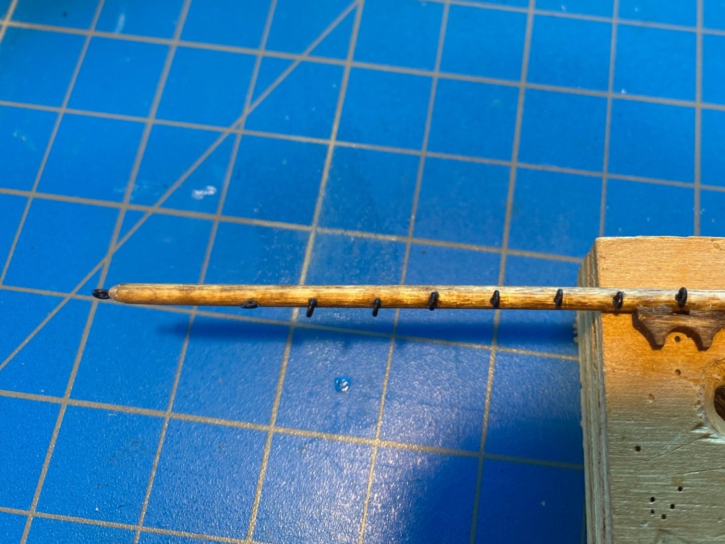
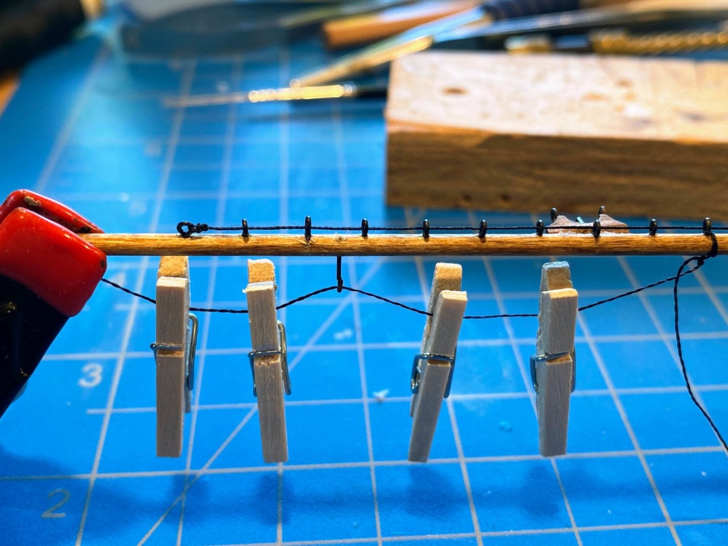
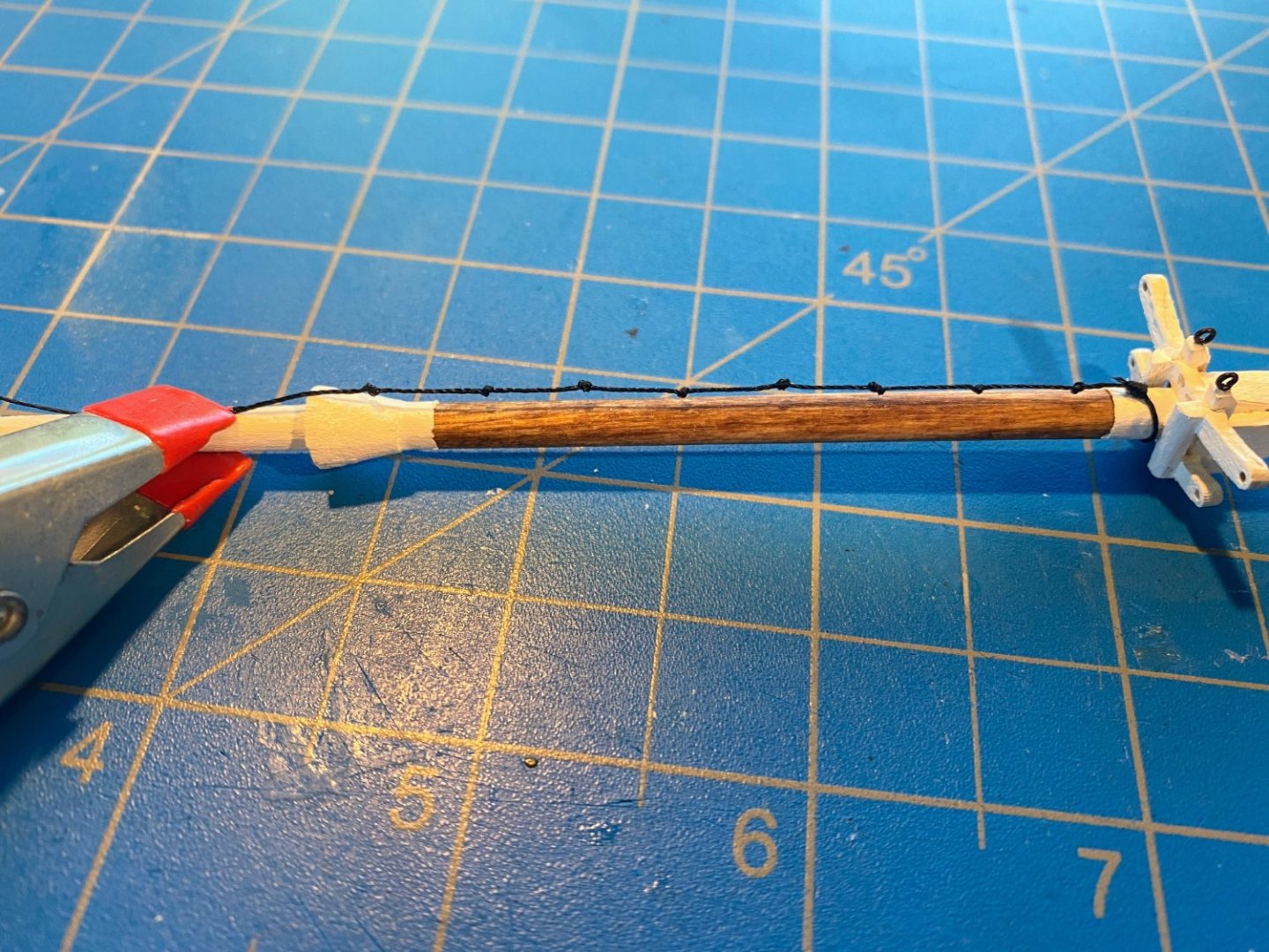
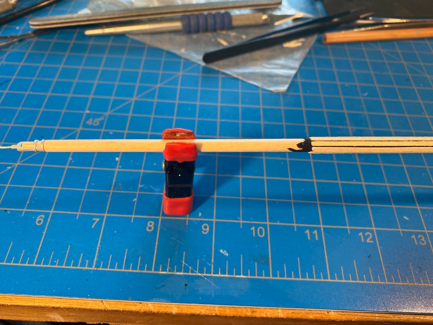
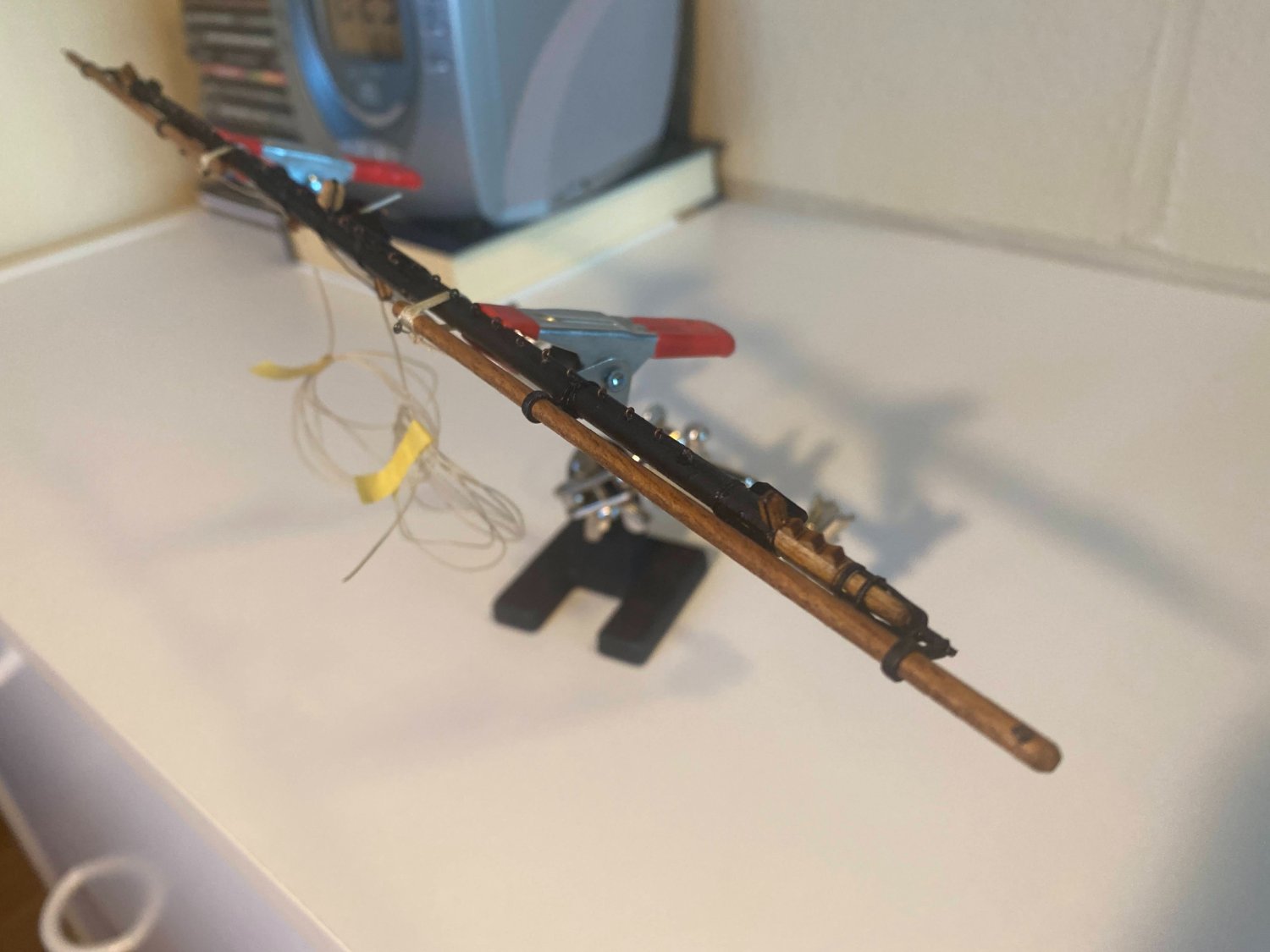
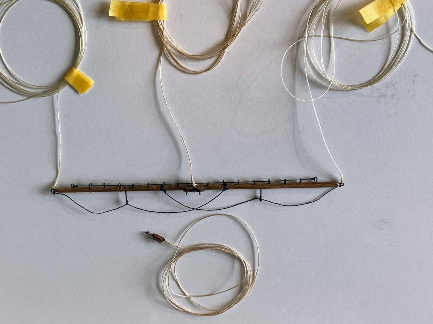
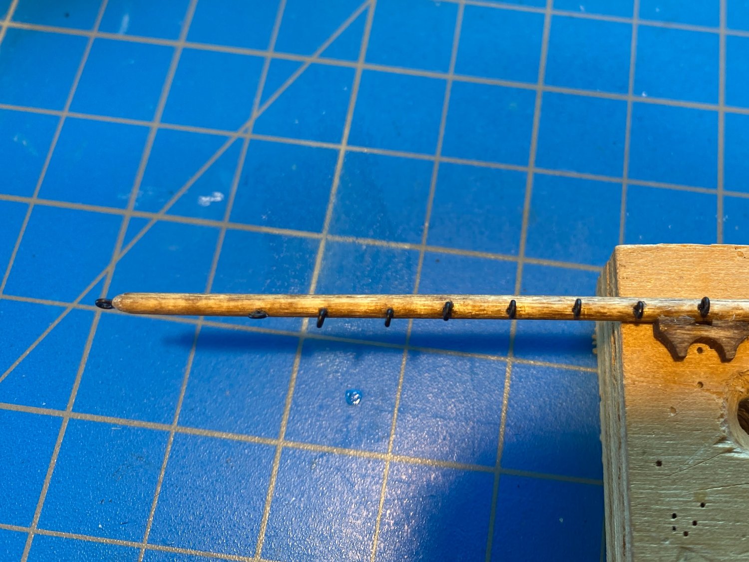
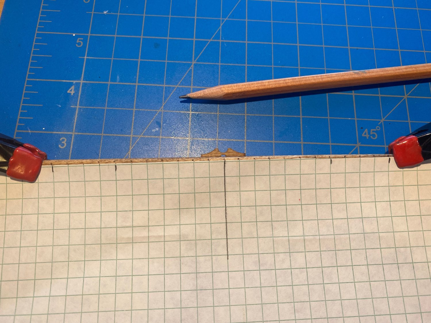
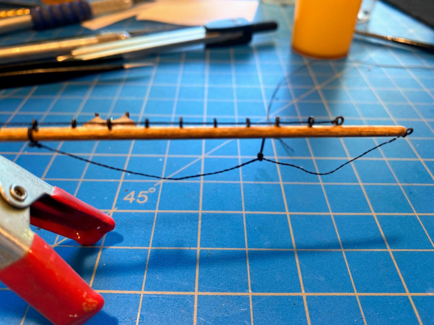
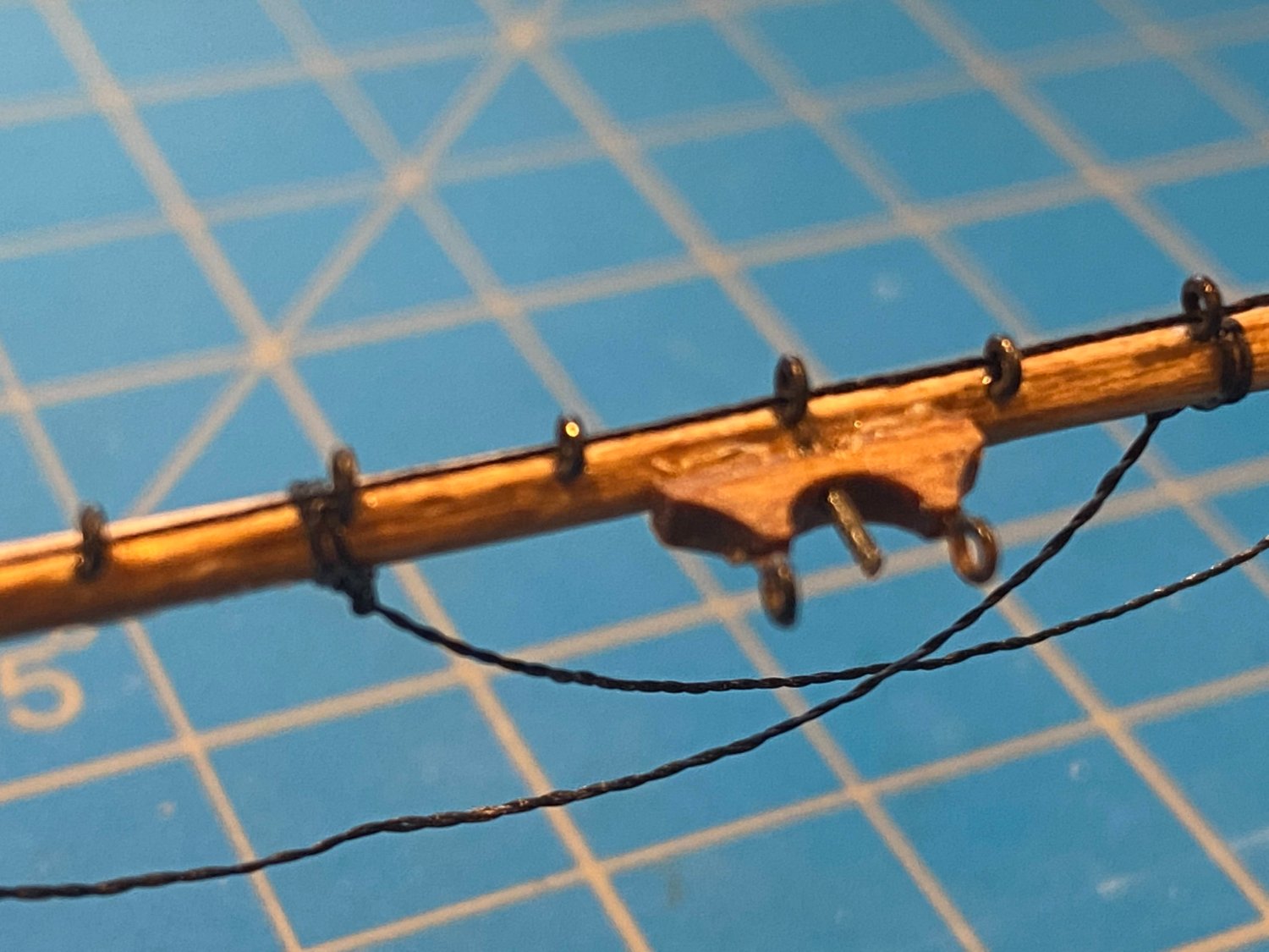
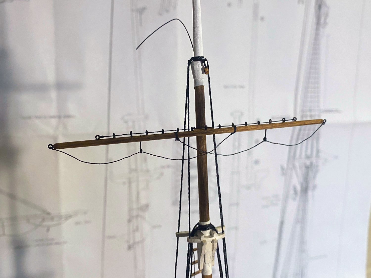
Onto the yards . . . The instructions begin this phase of the build by saying that the lower and topsail yards are each constructed of three pieces: two dowels connected by a square piece that will be shaped to an octagon in cross section. But there are some problems here: The square middle pieces are not referred to in the parts list. The lower yard middle piece is said to be 5/16” square, and the 3” long piece of that size has already been used for the square base of the topmast. The instructions don’t specify a size for the topsail yard’s middle piece, and that would presumably be 1/4” square, of which there does appear to be enough left over. Dowels for all of the yards are mentioned in the parts list and are supplied. However . . . Looking at the plans, these octagon sections are supposed to have eight 1/32” thick battens glued onto them. The diameter of the spars, including the battens, is 5/16” and 1/4” for the lower and topmast spars respectively, including the battens. Not counting the battens, those two spars should be smaller than specified in the instructions; they should be 1/4” and 3/16” respectively if made consistent with the plans. The battens are mentioned nowhere in the text of the instructions (but they do appear in one of the pictures). Did the author of the instructions assume that octagon midsections would be sufficient without battens and the preparer of the plans feel differently? Who knows. In fact all of the dowels are too large, if we assume the plans are correct. Here is what I am using: Royal: 3/32” instead of 1/8” Topgallant: 1/8” instead of 5/32” Topsail: 3/16” instead of 1/4” Lower: 1/4” instead of 5/16” Having gotten that all straightened out, I decided that I would build the royal yard first, as the yards get more complex the closer they are to the deck. Three things I will do differently next time. First, I will glue the so-called “tye cleat” on after drilling all the holes, as it broke off twice while drilling. Second, I will drill all the holes before gluing anything into any of them. And third, I will try to avoid falling asleep before finishing this tedious line of drilled holes. Or I assume that is what happened when I drilled the last three of them, as can be seen below. 😀 Or maybe the graph paper I was using for spacing and to keep things in line slipped. ********* In any event, fortunately the eyebolts were only dry fit into the holes when that picture was taken and I was able to take some corrective action. Also, the instructions have you string wire through the eyebolts to finish the jackstay, but I think thread looks just as good and is a lot easier to work with. In the category of making things easier . . . I spaced these holes 1/4” apart, matching the graph paper and resulting in fewer eyebolts to install. The instructions would space them at 5/32” on this yard and the topgallant, and 3/16” on the topsail and lower yards. Perhaps the most challenging part of this yard is the foot ropes, which need to hang naturally as rope would but thread doesn’t. I first tried soaking, stretching and drying the thread, but while that was somewhat successful, it didn’t take all the kinks out, and sometimes it simply wouldn't hang the way I wanted it to. The approach suggested in the instructions is to dip the thread in diluted white glue, let it dry, then install it and bend it to the desired shape. That worked! Or at least with some effort it did. The little 1” clothes pins I just bought were a big help. In the picture below I simply led the thread through the eyebolt, but when rigging the other side, I put a clove hitch there, which was very helpful. I referred to the “so called' tye cleat since I haven’t seen that term used anywhere else. On my Niagara build, Model Shipways uses the terms “batten” or “yoke”, the latter being the most descriptive to me. Whatever it’s called, I drilled a hole through it and part way into the yard, and I glued a thin wire pin in, to more securely attach it to the mast, in which I drilled a similar hole. The eyebolts in the yoke are for securing the parrel, which wraps around the mast. Finally, the royal yard dry fit onto the mast. I think I should have added at least one more eyebolt to each end of the jackstay. That stray thread up there is the top of the monkey rope, which I will cut off once I have added two more blocks to the mast there.


- 163 replies
-
- 5
-
-
- Model Shipways
- Constitution
- (and 2 more)
-
Thanks for the kind words Bob. I enjoy reading your comments prolifically scattered all over these boards, and I look forward to progress on your current builds. Thanks for the tip Johnny. I spent several years in the Boy Scouts and was an avid sailor for at least the first two decades of young adulthood, but I don't recall coming across the cow hitch. I'll give it a try.
- 163 replies
-
- 1
-
-
- Model Shipways
- Constitution
- (and 2 more)
-
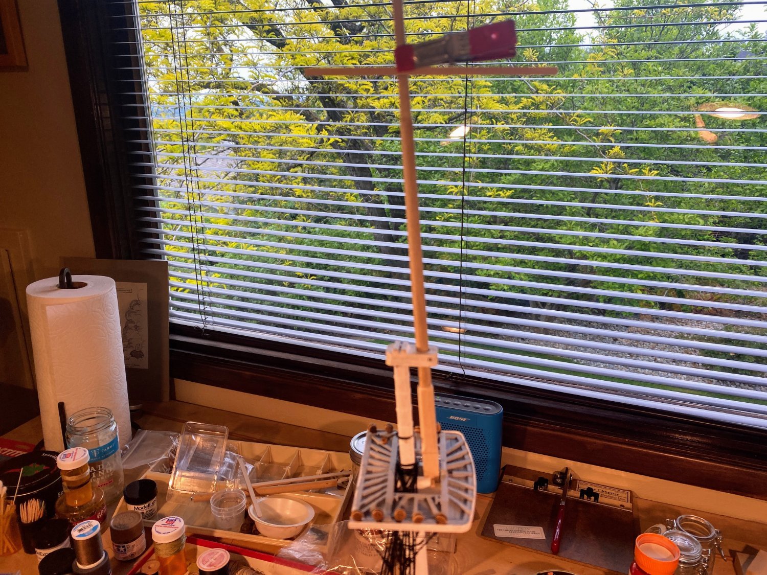
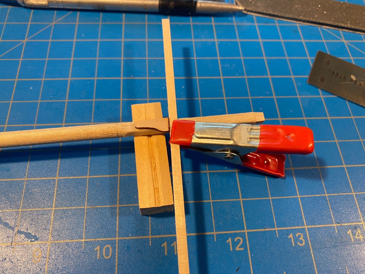
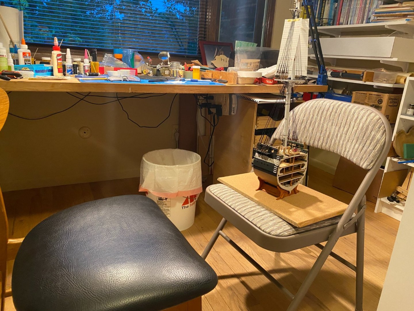
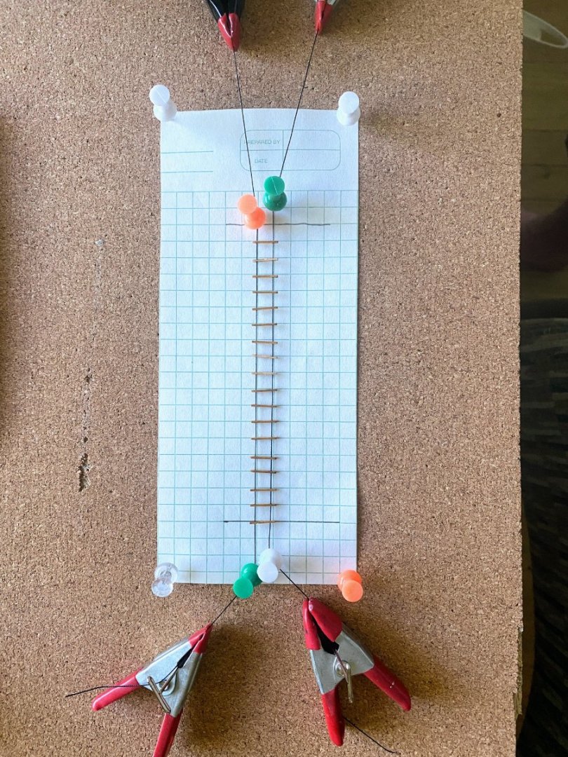
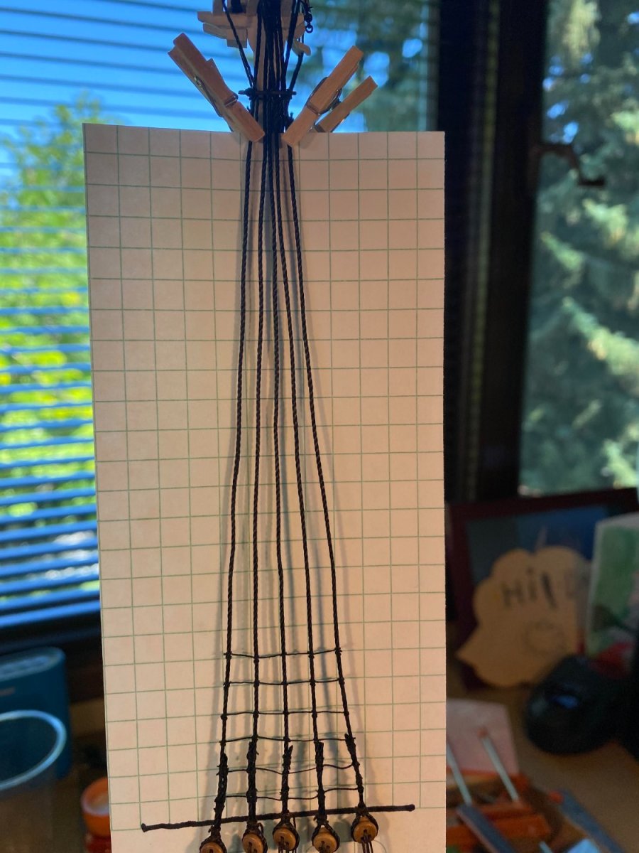
A quick update on ratlines. It’s tedious as I expected, but if you get into a certain rhythm, it can go pretty quickly. I’m doing two or three pairs a day, while I work on the yards. While wandering around these forums recently I came across a link to the following youTube video, which I found to be very helpful. https://www.youtube.com/watch?v=yMmGFWJhi8E Three things I've been doing a bit differently than shown on the video. First, I found some ¼” square graph paper lying around the house, and I put a piece of that behind these shrouds rather than plain white paper. Recall that the topgallant and royal shrouds are right behind these shrouds, and I was hoping the fit would be tight enough that the graph paper would stay in place. It wasn’t, and the paper frequently slipped (the black line being where a sheerpole is to be installed. Second, instead of using a hook to pull the thread through to the front, I use tweezers. I fear that getting the hook far enough back there might damage the shrouds. Third, instead of tying an overhand knot on one of the end shrouds (left one in the case of the video), I tie an overhand knot on the middle shroud and work my way outward in both directions. That way if I later discover that I didn’t get the clove hitch on the next shroud quite tight enough (or otherwise screw it up), then I only have potentially 2 clove hitches to redo instead of 4. In addition to graph paper aiding immensely in getting the ratlines lined up close to correctly, looking at it up close has the added “benefit” of disclosing such things as deadeyes not in line and lashed double shrouds not ending at a consistent height (see above and below). I found that these ratlines are at an awkward height, a little too high to sit comfortably at my work bench and a little too low to work comfortably standing up. The solution was to place the model on a chair. Finally, I came across something on Amazon that may be a solution I’ve been looking for for a long time: 1 inch long mini clothespins. They arrived in the mail yesterday. There are many times when I want to temporarily clip something to a shroud or hang just a little bit of weight on the end of a piece of rigging, but conventional mini clamps are too heavy and distort the rigging I’m working on. These things are so light you can move them around a table by gently blowing on them. Just what I needed to secure the graph paper to the shrouds.


- 163 replies
-
- 2
-
-
- Model Shipways
- Constitution
- (and 2 more)
-
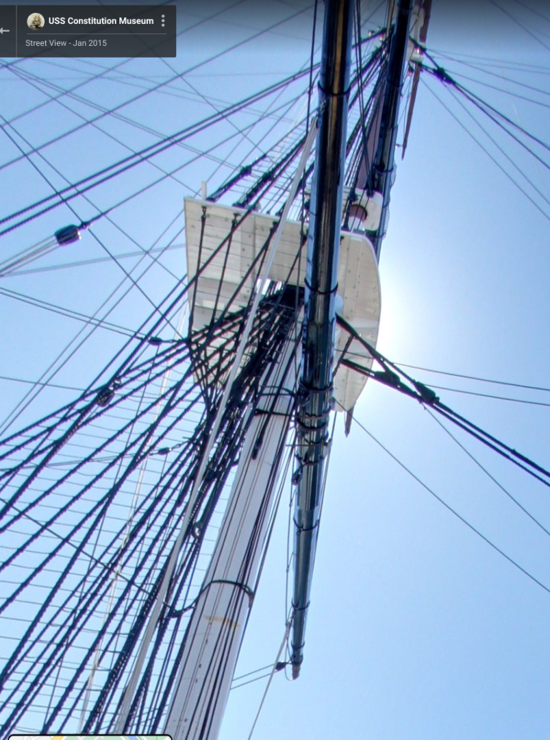
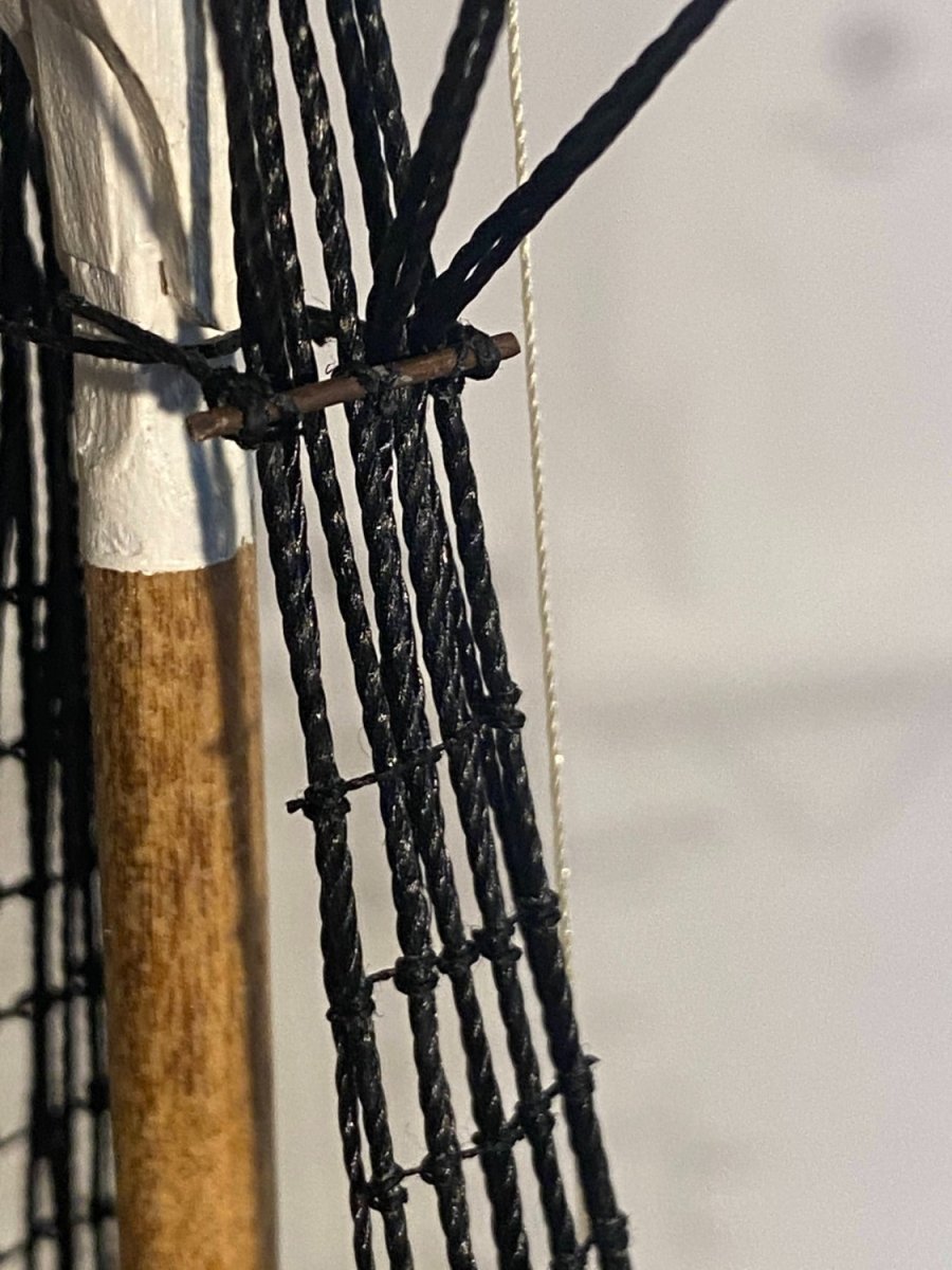
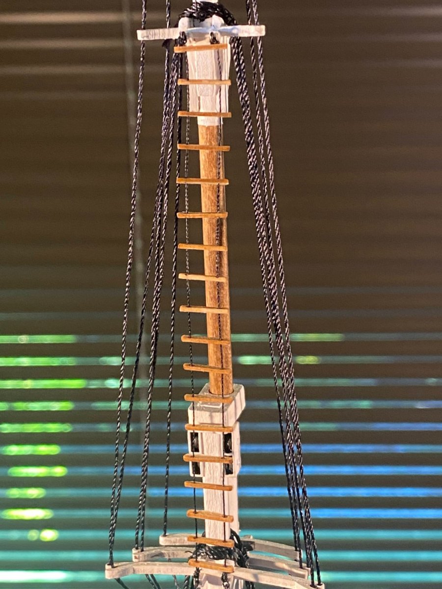
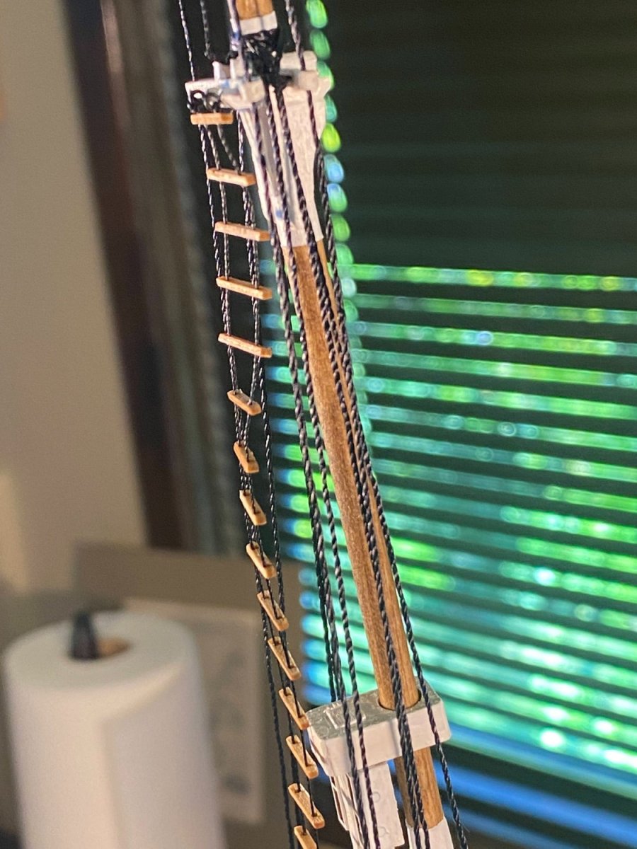
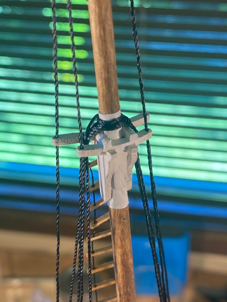
Shrouds . . . topmast, topgallant and royal. I’ve been busy building, not taking very many pictures, and not writing at all. So I’m a little behind with this blog. First, a couple of general comments about these upper shrouds. I have not served any of the shrouds. I do not have a serving machine, and while I would be willing to purchase one if I really wanted to, I’m concerned that serving would make the shrouds very difficult to work with, and would add a detail all but the most discerning eyes would never notice or appreciate. In other words, not worth the effort. Feel free to disagree and show me the error of my ways. The instructions have you use the same thread for the lower and topmast shrouds, but it seems to me that the shrouds should decrease in diameter the higher up the mast they are. The following screenshot from the Google tour makes it clear that the topmast shrouds are noticeably thinner than the lower shrouds. Also, on the real ship, no need having any more weight than you need up there. I used the kit supplied .040” thread for the lower shrouds, and I think I used kit supplied .020” thread for the topgallant and royal shrouds, but I found something in between for the topmast shrouds. That thread, left over from some other build, was extremely stiff, and although I soaked it two or three times and hung it weighted to dry, it proved difficult to work with. Worth the effort though. As mentioned previously, I rigged the topmast shrouds before stepping the topgallant mast. That way I could do the following: I seized a deadeye onto one end of the shroud, lashed it to the corresponding deadeye in the fighting top, ran the shroud up and around the top of the topmast, back down to toward the fighting top, and tightly tied a thinner piece of thread around it right where I wanted the adjacent deadeye to be. I then unwrapped it from the mast and brought it all down to earth where I could easily seize on that second deadeye. The first photo below shows that, but it’s not a very good picture and you have to look at it pretty closely to see what I mean. What I just said applies to the four aftmost shrouds on each side. The forward shroud on each side goes up and around the mast, but back down the opposite side of the ship to be the forward shroud on the other side. Same approach though in undoing it all after marking where I wanted the deadeye to be on the second side. Too much text . . . time for a couple of pictures. Next challenge was installing short (½” long) futtock staves even with the bottom of the topmast cheeks. These are not only seized to the topmast shrouds, but each is prevented from being pulled outward by a catharpin; that is, a piece of rigging seized to one end of the stave, wrapped around the topmast and seized to the other end of the stave. These are needed because the topgallant and royal shrouds will run up the inside of the topmast shrouds, run inside and above the futtock staves, then run up and out to the topgallant crosstrees as futtock shrouds, before running further up to their endpoints on the topgallant mast. I found it easier to seize these catharpins to the futtock staves first, then seize the staves to the topmast shrouds. With the topmast shrouds completed, I installed the topgallant mast.With all the masts now in place, I installed the Jacob’s ladder, which was pretty straightforward. Except that the top of the ladder has a built in twist, and I haven’t figured out how to straighten it (pictures taken out of order, after rigging the upper shrouds). A photo in the instructions numbers the eyebolts in the fighting top just behind the topmast shroud deadeyes, 1 through 5 aft to forward. As described in my prior post, I seized lengthy pieces of thread to hooks that I attached to eyebolts 2, 3 and 4. Number 4 was rigged first, and that one ran up and around the futtock stave, through the hole in the middle topmast cross tree, and up to the topgallant mast just above its crosstrees where it was seized in place. Number three ran a similar course, but it went around the topmast and back down, through the hole in the forward topmast cross tree, and after passing behind the futtock stave, down to a hook to be attached to unoccupied eyebolt 5. The thread attached to eyebolt 3 did the same thing except after passing through the notch in the middle topmast cross tree, it passed through holes in the topgallant crosstrees, before wrapping around the topgallant mast at the shoulder, then took the same long route back down, where it eventually hooked into eyebolt 1. Except when I forgot to run it behind the futtock stave on the way down, a potentially costly mistake I noticed (fortunately) just before applying glue to the hook seizing at eyebolt 1. In each case where a shroud wrapped around the mast and headed back down, I seized the two parts of the shroud at the mast. Perhaps not necessary in the case of the topgallant shrouds but certainly necessary in the case of the royal shrouds. These royal shrouds also secure the top end of the monkey rope in place. Three blocks will eventually be seized to the mast at this location, giving additional security to the top end of the monkey rope, and this end of the rope will not be clipped off until those blocks are in place. Now several pictures, somewhat random order. Next will be sheerpoles seized to the bottoms of the topmast shrouds, and then there is something else. . . oh yes, ratlines!


- 163 replies
-
- 5
-
-
- Model Shipways
- Constitution
- (and 2 more)
-
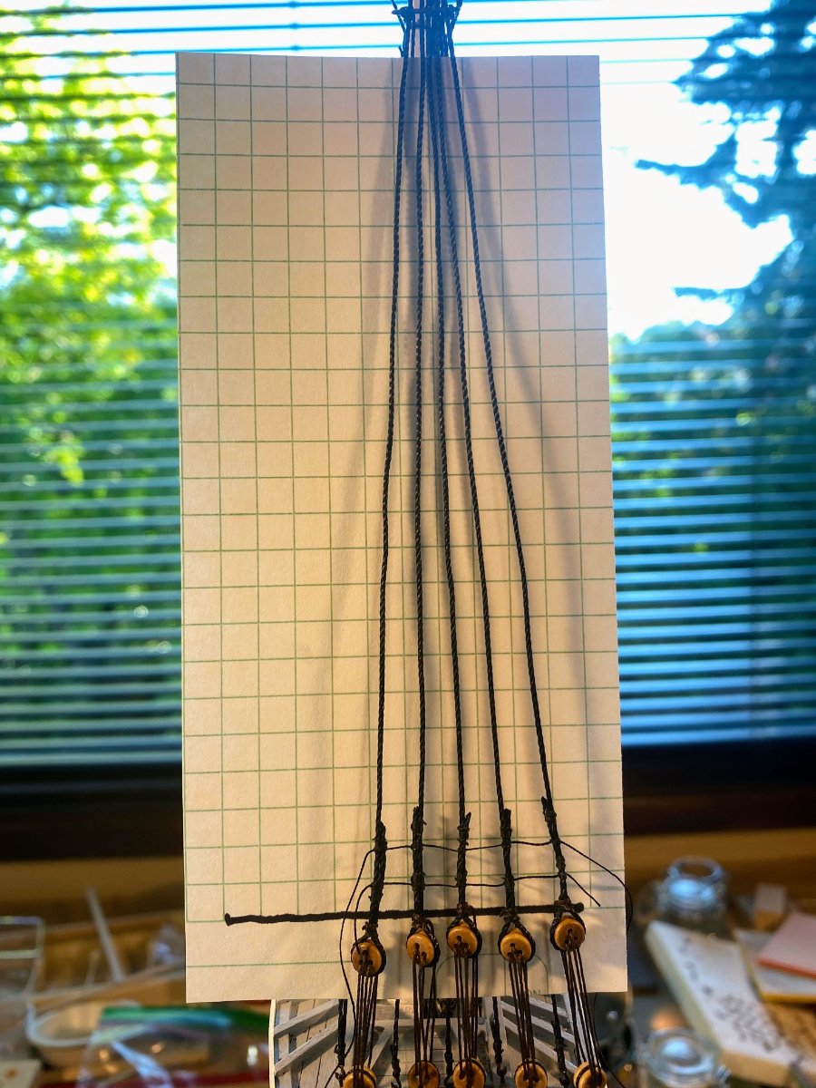
Before tackling the topmast shrouds . . . . I mentioned before that there are ten eyebolts that need to be added to the fighting top and that it would have been easier to do that before the deadeyes were added to the fighting top and it was installed on the mast. These eyebolts, just inside the shroud deadeyes, secure the topgallant and royal shrouds. The only mention of those eyebolts in the instructions is in a caption to one of the photos. Holes for three of these deadeyes are pre-drilled in the fighting top deck, but those holes are considerably larger in diameter than the eyebolt stems. My solution for that problem was doubling the stems back on themselves so they would fight more tightly in the holes. The instructions say to add the topmast to the lower mast just before installing its shrouds. They don’t say anything about when to add the just completed topgallant mast. My initial thought was to glue these upper two masts together, add the Jacob’s ladder and the monkey rope, then glue the assembled masts to the lower mast. But then it occurred to me that looping the topmast shrouds over the top of the topmast would be easier than threading the shrouds through the narrow gap between that mast and the topgallant mast. So I did what I was told and glued just the topmast in place. Edit added a couple of weeks later: This would be a good time to add holes for pins to both these masts where the topgallant and royal yards will be attached. It's a lot easier to drill these holes when the masts are resting on top of your workbench than when the masts have become part of the ship. Similarly, use a drill bit to clear any dried paint out of the holes at the end of each mast's crosstrees. I knew that installing the topgallant and royal shrouds after installing the topmast shrouds (as instructed) would be near impossible. So I cut the necessary pieces of thread for the upper shrouds, attached a hook to one end of each of them, and hooked six of them in place on the three middle eyebolts on each side, adding a small drop of thick CA to be sure they stay there. On each side, one topgallant shroud and one royal shroud will loop around the appropriate part of the topgallant mast and come back down to an unoccupied eyebolt on the either end of the row of eyebolts. Hopefully those eyebolts will be easily accessible since they are on the end. However it won’t be possible to complete these upper shrouds until the topmast shrouds are completed, since the former shrouds run up just inside the latter, then bend outward around a futtock stave attached to the topmast shrouds, before engaging with the topgallant crosstrees. And of course the topgallant mast must be installed if these shrouds are to engage with its crosstrees This means a large amount of thread has to be stored, kept untangled, and kept separated from the topmast shrouds, somewhere up the mast assembly. My approach (and I am sure there are better ones) can be seen in the last of these photos. The forward topmast shroud passes around the topmast and down the other side, and In these photos you can see that I have have lashed together the deadeyes for that shroud on the port side and just started to do so on the starboard side. The other topmast shrouds will loop around the topmast and come back down the same side. By comparison, putting together the Jacob’s ladder and the monkey rope was pretty straightforward and easy. I used graph paper as part of a jig for the former, and simply used my eyeballs to properly space the knots in the latter. The top of the monkey rope won’t be secured until I have looped topgallant shrouds over where it is secured at the bottom.


- 163 replies
-
- 4
-
-
- Model Shipways
- Constitution
- (and 2 more)
-
ELV, I recently discovered that there is an organization of model ship builders, the USS Constitution Model Shipwright Guild https://www.usscmsg.org affiliated with the USS Constitution Museum. I suggest contacting them to see if they know anyone who would be interested in purchasing those kits. Good luck
-
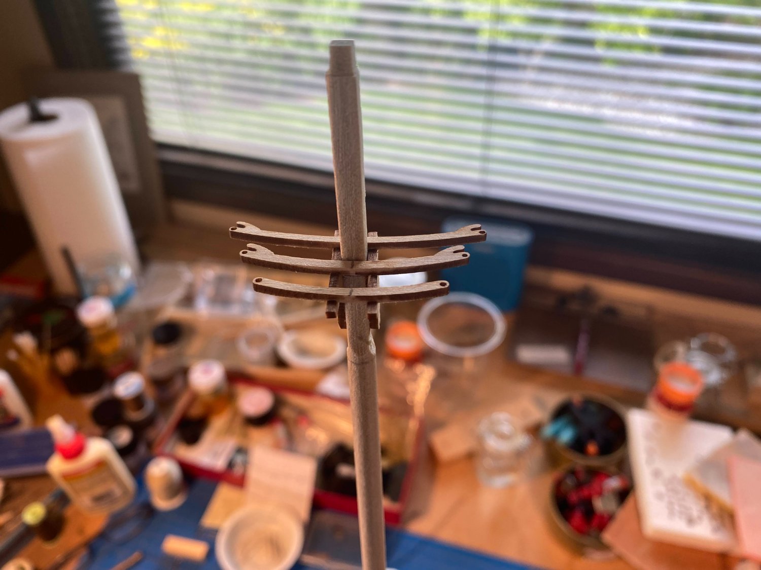
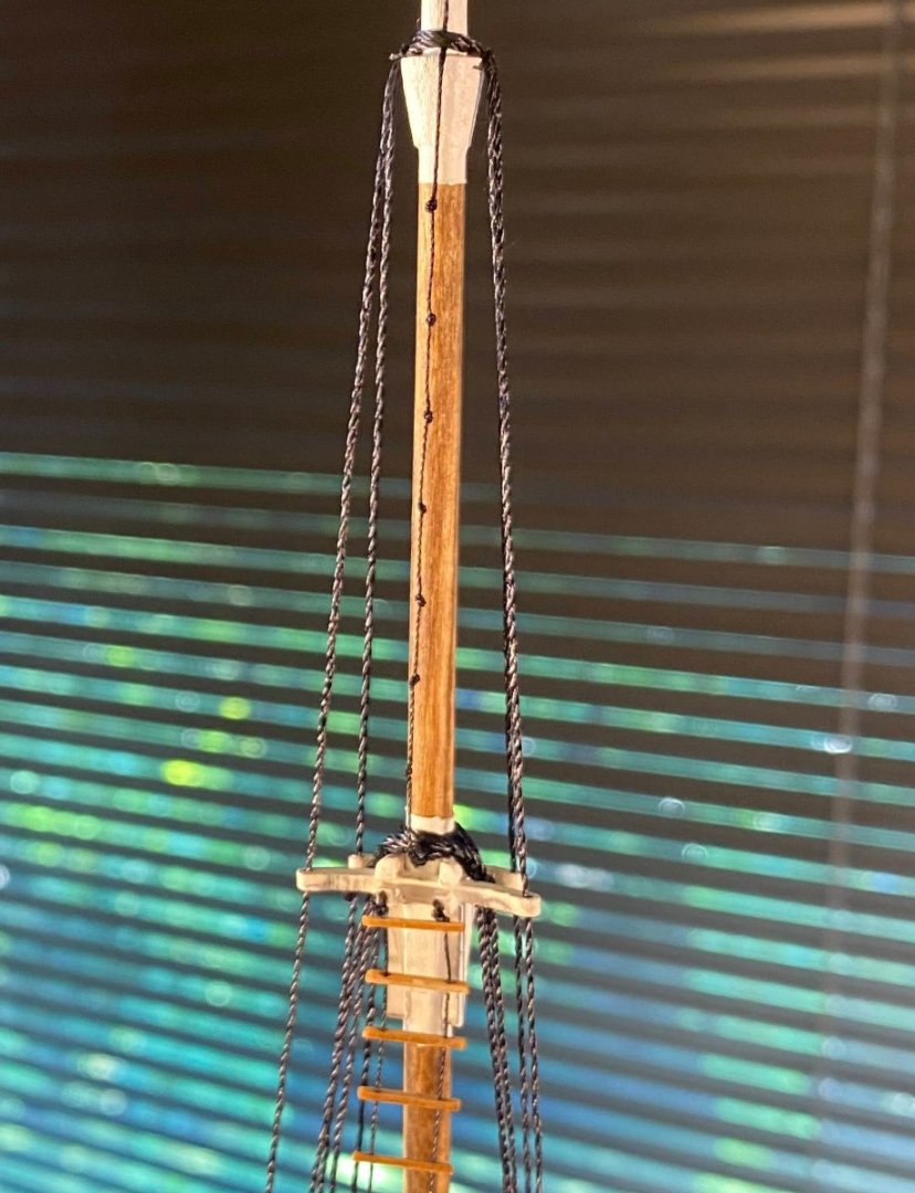
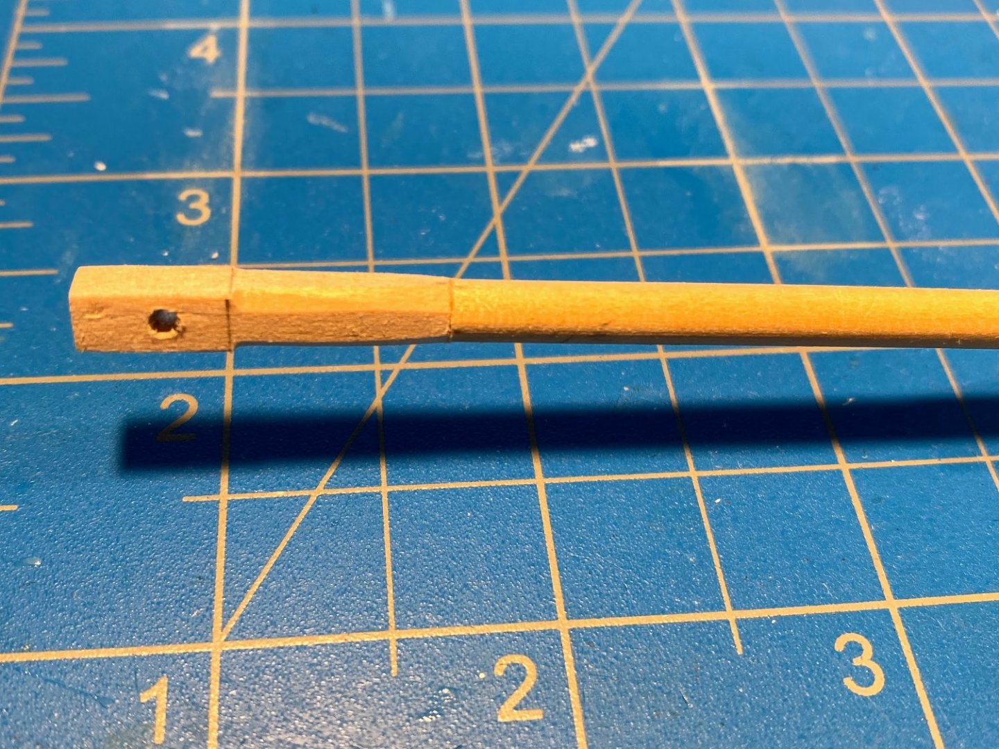
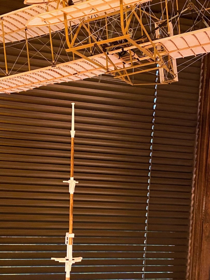
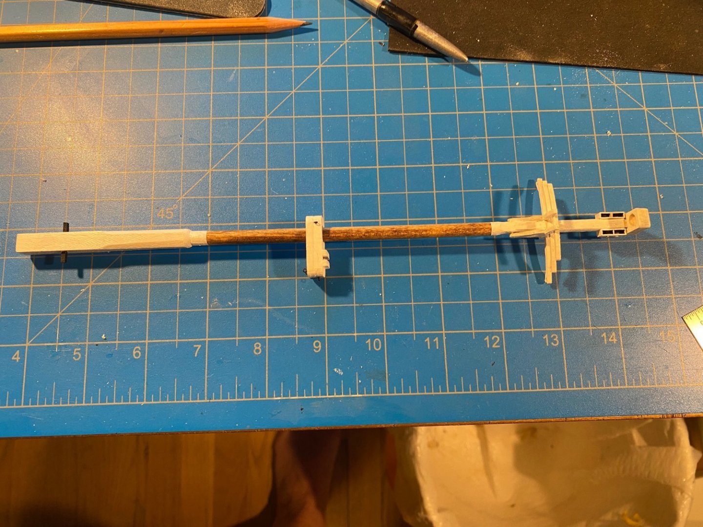
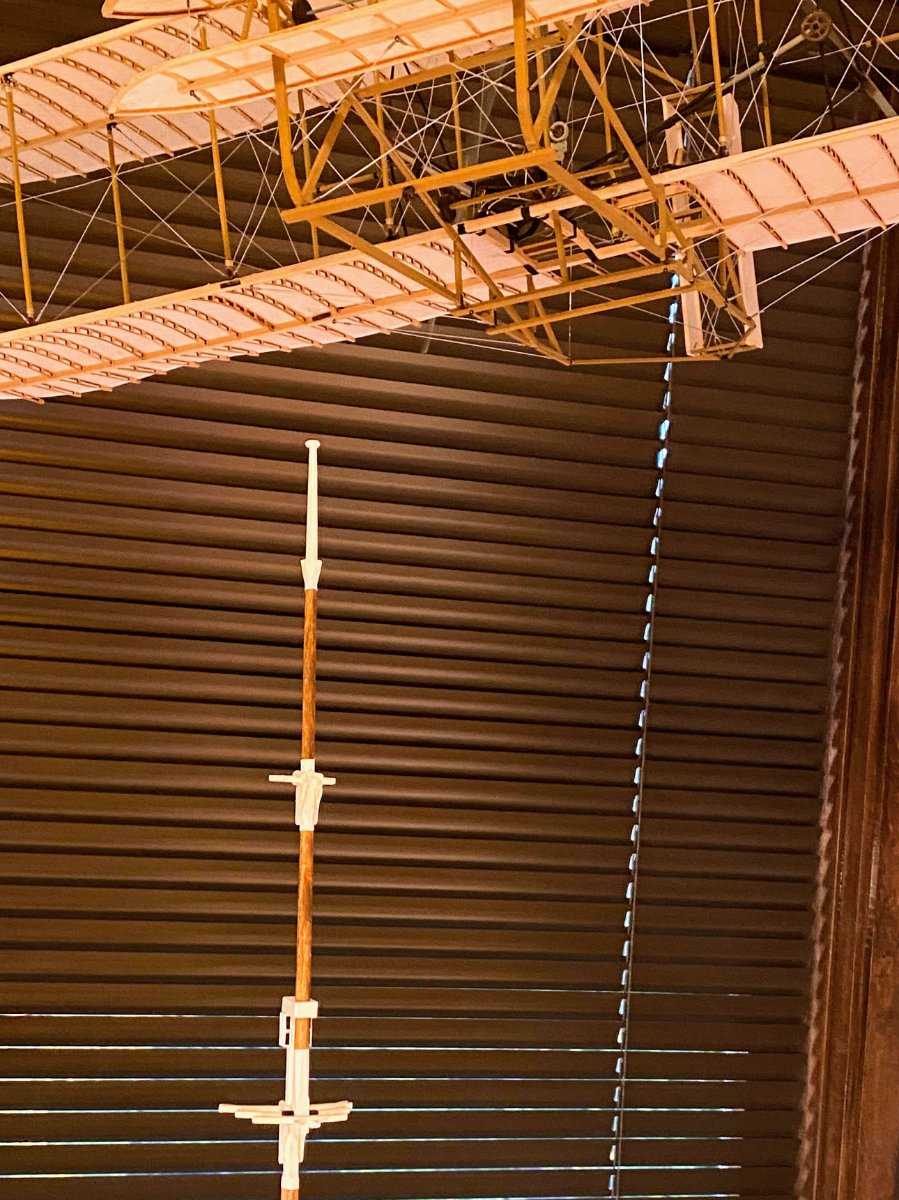
Building the topgallant mast is mostly the same as building the topmast, but on a smaller scale. First, though, be aware of the following errors in the instructions: The bottom part of the mast is said to be cut from 1/4” square stock, when the plans and parts list show/say 3/16” square. 1/4” is clearly too large. The bottom part is said to be 1 5/8” long, which includes a 1/4” peg to fit into the hole you drill into the dowel part. If you don’t include the peg (I didn’t), that translates to 1 3/8”. The plans show the lower part to be 1 1/16”, which appears more consistent with pictures of the real ship. Most of the mast is made from a dowel, described as 1/4” round, when the plans and parts list show/say 3/16” round. Again, 1/4” would be way too large. The instructions say to sand a “slight taper” in the dowel from 1/4” to 1/8”, but on the plans it’s clear that that the mast needs to be tapered from 3/16” to about 1/16”, a fairly dramatic taper. As I did with the topmast, I connected the two parts of the mast with a pin cut from a paper clip (regular size this time) and drilled appropriately sized holes in one end of the dowel and one end of the square part. The top (approx.) half of the square part is sanded to an octagon cross section, similar to the top mast. My octagon vaguely resembles a stop sign, but at this scale it’s close enough. The topgallant cheek/crosstree/trestletree/wedge/bolster assembly is also similar to the one on the topmast, but with only two crosstrees instead of three. It’s enough smaller than the topmast assembly that working with the pieces proved to be challenging given my large, clumsy, arthritic thumbs, but it was doable. This time I assembled two trestle trees and one crosstree, and glued it onto a section of the mast I had sanded square. I then added the other parts, gluing the cheeks in place last. As with the topmast assembly, the bolsters were laser cut (this time the appropriate size), but they are so small that I found sanding them to a quarter round to be virtually impossible. So instead I used some 1/16” square stock, rounded an inch or so at the end, then cut off pieces of the appropriate length. About 1 1/2” down from the top there is what is referred to as a “shoulder” -- an octagon cross section, cone-shaped piece that wraps around the mast. The instructions vaguely direct making this piece from four 1/4” x 1/4” x 1/8” blocks. I took what I think was a simpler approach -- sand beveled about 3” of a 1/16” stick, then cut off eight or nine 1/4” pieces and glued them around the mast. Using a Dremel tool I shaped it into a cone. In cross section It is supposed to be an octagon, but the difference between that and my circular one shouldn't be noticeable, especially when draped with shrouds. The mast cap, or truck, is a laser cut circle with a predrilled hole. The hole needed to be enlarged some, and the resulting donut needed to be rounded so as to be oval shaped when viewed from the side. And now, 18th century mast cap meets early 20th century landing gear . . .


.thumb.JPG.1e48c6c63eee8d6f33b15b3ff34d2170.JPG)
- 163 replies
-
- 2
-
-
- Model Shipways
- Constitution
- (and 2 more)
-
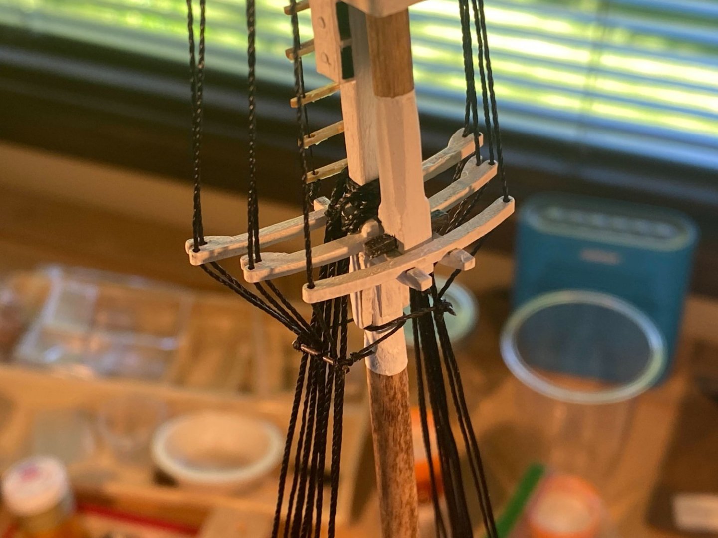
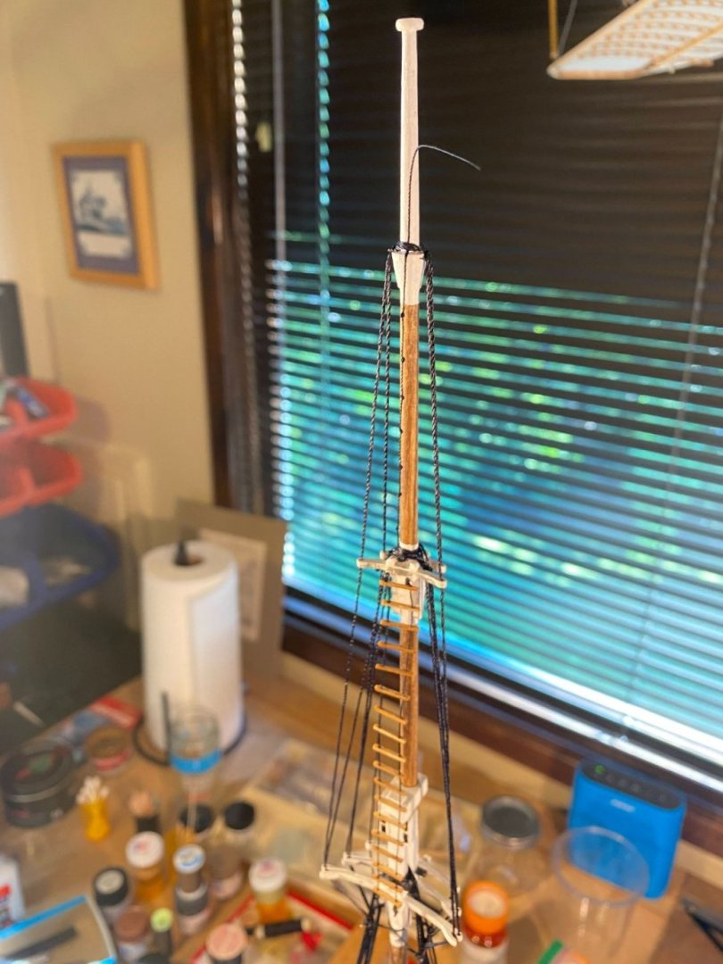
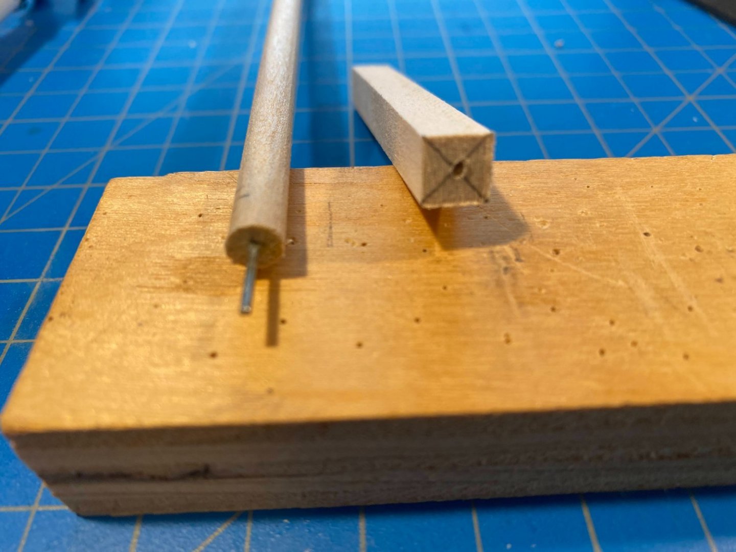
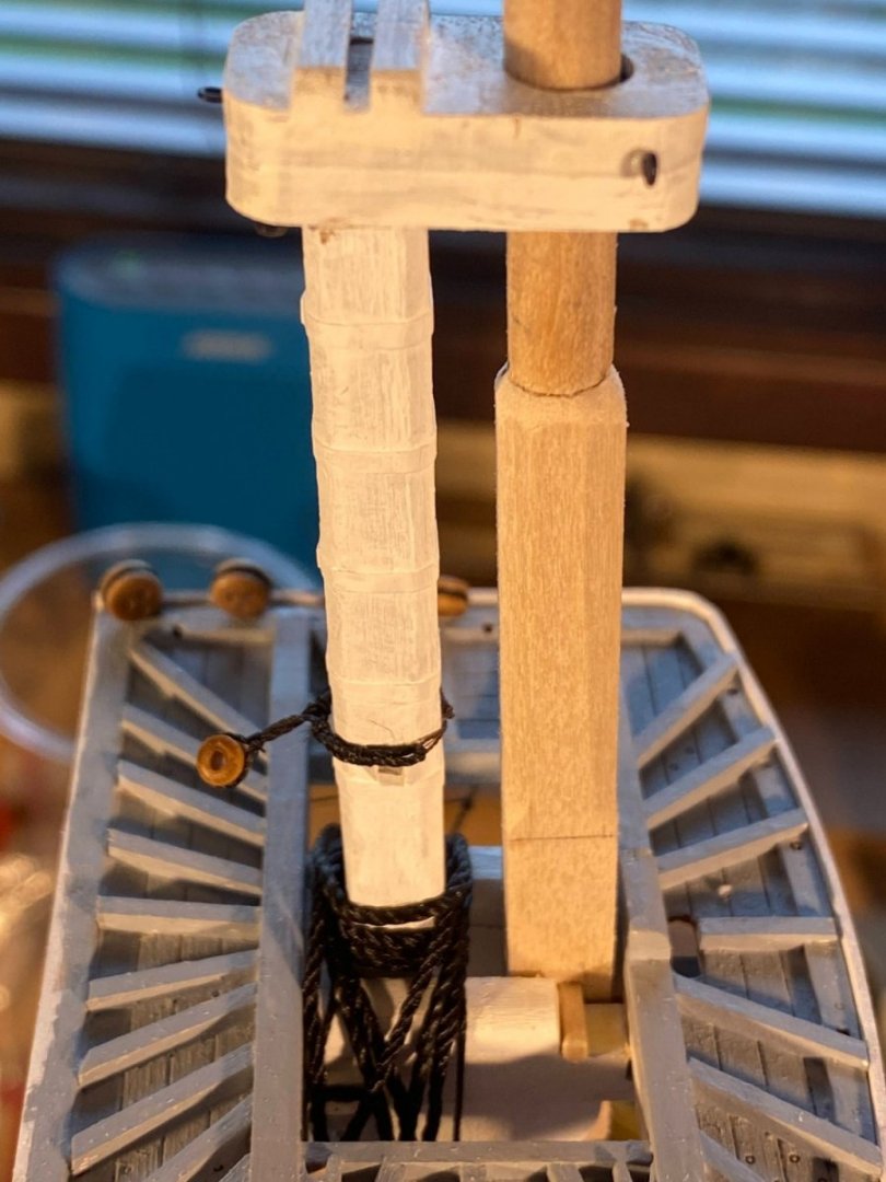
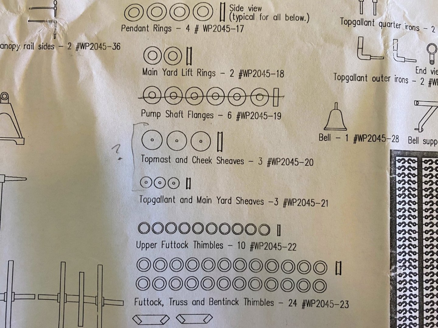
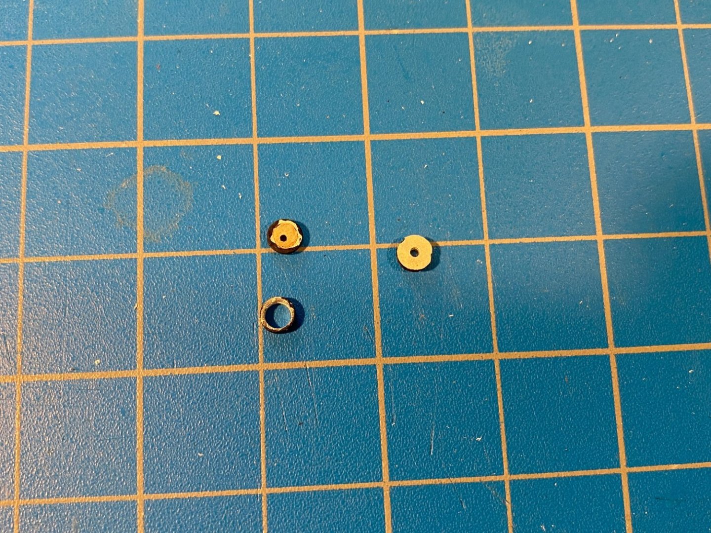
Here is the topmast completed. It is made from two pieces, a 5/16” square short bottom section and a considerably longer 1/4” dowel. The length of the dowel specified in the instructions is about 1/4” short of what is shown on the plans, and I follow the plans when there are discrepancies between the two. The instructions direct turning or carving a 3/16” peg on the bottom of the dowel to fit into a hole drilled in the square part. I found it easier to drill a considerably smaller hole in one end of each piece of wood to fit a metal rod cut from a large paper clip. For the fids I drilled a couple of 3/32” holes on each side of the square piece, into which I pressed a couple of pieces of 1/16” square stock. The upper half of the square piece was then carved to an octagonal cross section, and then rounded at the top to make a clean transition to the dowel. I had already cut and painted a spacer, which I now glued in place, to fit in the fighting top between the lower mast and the topmast. When I dry fit the topmast into place, I found that it had slightly more rake than the lower mast. A little sanding of the spacer and insertion of a very thin shim in the forward part of the fighting top hole solved the problem. Before doing any of the following, it is important to slide the lower mast's mast cap onto the topmast. The upper 2” or so (check the plans) of the topmast is cut to a 3/16” square, with a 1/8” square at the very top to fit into its mast cap. Two cheeks are then glued on to the mast near the bottom of that squared section. I put a fair amount of effort into getting the cheeks properly aligned so that their tops are parallel to the fighting top and not perpendicular to the mast. Then the two trestle trees were added (being sure they were parallel, aligned fore and aft, and not twisted relative to the hull), and the three cross trees were glued into slots in the trestle trees (together with the cheeks, all laser cut). Close, but not exactly right . . . Focusing on alignment I made an error. Consistent with a photo in the instructions, and not consistent with the plans, I glued the cheeks in place with their back edges more or less flush with the aft side of the mast. Instead the back ends of the cheeks should be in the middle of each side of the mast, so that their front portions more or less “grasp” the bottom of the topgallant mast. I was tempted to pry the cheeks off to correct this, but I didn’t notice the problem until the trestle trees were glued to the cheeks and the cross trees were glued to the trestle trees. I decided that prying the cheeks off at this point risked doing serious damage. Similar to the fighting top, this assemblage has a pair of bolsters over which the shrouds will run. Oddly they are laser cut when they could be easily cut from square stock (one side needing to be rounded in either event). More odd still, the laser cut pieces are 1/8” square when they should clearly be 1/16” square (as shown in the plans; see above). Easily remedied but as I said, odd. Then there are two very thin, laser cut wedges which the instructions say are to be glued to the mast with their tops flush with the tops of the cheeks. For some reason I did not put them on until the trees were in place. I therefore noticed that they won’t support anything (assuming that’s their purpose) unless they are placed slightly higher on the mast, pushing up against the bottom of the middle cross tree. Finally just below the mast cap there are a couple of laser cut boxes, each containing a couple of sheaves. The instructions refer to the sheaves in bold type (the convention used to show that something is a supplied part), but no part number. Plan sheet 3 has drawings of all the parts, with descriptions and part numbers. Taking a look at that, I found “Top Mast and Cheek Sheaves”, which seemed to be what I was looking for if you eliminate the “and”. But . . . there are only three of them, not four, and they are too small to fit in the laser cut cheeks. Just below them on the plan sheet are “Topgallant and Main Yard Sheaves”, that fit perfectly, but again there are only three of them! Doing a search of the pdf version of the instructions, I find that there is a “sheave hole” in the topgallant mast and in the main yard (and the other three yards as well), but no mention of sheaves to go in those holes. So I decided to use those pieces, along with one of the thimbles I didn’t use rigging the futtock shrouds a couple of weeks ago. I glued a thin slice of dowel in the large hole of the latter and then drilled a small hole to accommodate a nail which simulates the sheave axle. Now that these cheek sheaves are in place, they look to me too large and a bit out of place. I took a look at the Google Maps ship tour to see how they look on the real thing, and they aren’t even there! Which makes me tempted to pry them off. Searching the instructions I can’t find any lines that run through them. I’ll leave that decision to another day. Meanwhile I have started working on the topgallant mast. Spoiler alert . . . don’t rely on the dimensions referred to in the instructions; many of them are wrong.


- 163 replies
-
- 4
-
-
- Model Shipways
- Constitution
- (and 2 more)
-
Wise words well spoken, especially "fun to do" and "the builder is the master of his model world. If it pleases him (her), then it’s good enough." Looking at more than just approaches to detail . . . I used the word "accuracy" above, but I think the better word to express my goals would be "realism." I'm not into a lot of historical research, but I do want a model that looks something like the original one did. So I will never put a brass anchor chain on a model. But that's just me. A lot of bare brass, exotic woods, and wide deck planks with prominent treenails can make a beautiful model, displaying modeling skills I can only dream of. And there is some likelihood that my next build will be a kit from Occre. But the way I will do it, it won't look much like a typical Occre build.
-
Second time around installing the futtock/bentinck shroud assemblies went much better than the first time. I learned a few things from my first efforts, like looking at things from frequently changing different angles to find the one where I could see the most clearly. Counter-intuitively, a bright background (leaving the blinds open with all the light we get this time of year) did not create unwanted glare but shed some light on what is otherwise a lot of dark subjects (guess I hadn't figured that out when I took the first picture below). And of course it helps knowing the task is going to be challenging, instead of being caught by surprise like the first time. But before installing the futtock shrouds, the first thing I did was to tie the futtock stave to the lower shrouds. To do that, I had to know where the futtock shrouds would meet the lower shrouds, which I did by running a piece of beige thread (beige for better visibility) from the middle eyebolt on the underside of the fighting top to a place on the deck near the waterway. I tied another thread on the middle shroud to mark the spot. Next I tied a couple of ratlines to the shrouds above the stave; much easier to do without the futtock shrouds in the way. Then an unexpected challenge . . . securing the lower end of the bentinck shroud to the eyebolt in the waterway. I wanted to have the bentinck shroud in place, with its two parts loosely lashed together before lashing the two parts of each futtock shroud together. Several months ago I described having done that and finding it easier than I expected to get the hook into the eyebolt between the two cannons and all their rigging. Doing that was more difficult this time, because the mast and lower shrouds are now also in the way. But I got it done, and for good measure I managed to get a drop of CA on the hook and eyebolt. Unfortunately while installing the center futtock shroud, the seizing of the bullseye to the lower part of the bentinck shroud came undone. Now I regretted that drop of CA. With a great deal of effort, and fear that while using the necessary force I would tear apart a cannon, its rigging or a shroud, I managed to get the hook out of the eyebolt. I then put together a new lower part of the bentinck shroud, this time double seizing the bullseye. However, as I feared, there was no way I was going to get a hook back into that eyebolt -- too much CA left behind. So, again with a frightening amount of effort, I managed to pull the eyebolt out of the waterway. I then drilled a new hole in the waterway (somehow working my pin vice drill through the opposite shrouds and around the mast) and then managed to glue a new eyebolt in the hole. With a great sigh of relief I then hooked the new lower bentinck shroud to the new eyebolt, this time forgoing a drop of CA until the rest of the bentinck/futtock shroud project was finished. Finally after lashing all the futtock shroud parts together, I added ratlines to the futtock shrouds and got a few pictures of the finished project. Some parting thoughts as I look at the morass of black thread I have created. In another build log I was reading recently there was a discussion about detail, there in the context of treenails in deck planking. The builder had done a masterful job with toothpick tips as treenails, but both the kit’s supplied planks, and the treenails, were way too large to be true to scale. Of course some models are built to be beautiful models, at the expense of a degree of accuracy, and others are built with an eye toward accuracy--neither approach being better than the other. One post in the discussion of the latter approach expressed a preference for not trying to duplicate treenails at all, because they are simply too small to depict accurately. The poster’s philosophy regarding detail was “When in doubt, leave it out.” That led me to wonder whether trying to duplicate the three parts of each futtock shroud was a good example of a detail that could have been left out and whether a single piece futtock shroud, lashed to the lower shroud, would have been sufficient. Would that have resulted in a cleaner, easier to see finished product? One problem with tiny detail is that if you look closely enough to see it, you can also see flaws that disclose a less than masterful job. Just like closeup photos tend to show what we would just as soon not see. Unfortunately some of that can be seen in the photos above. Beginning to work on the topmast now . . .


- 163 replies
-
- 4
-
-

-
- Model Shipways
- Constitution
- (and 2 more)
-
Thanks for the likes and all the kind words. Funny thing . . . I struggled for five years in high school and college trying to learn French, and I never learned enough to carry on a meaningful conversation. Salty seaman's language on the other hand comes quite naturally. 😁
- 163 replies
-
- 1
-

-
- Model Shipways
- Constitution
- (and 2 more)
-
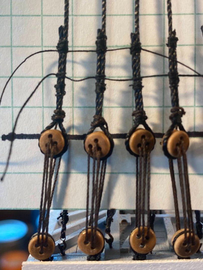
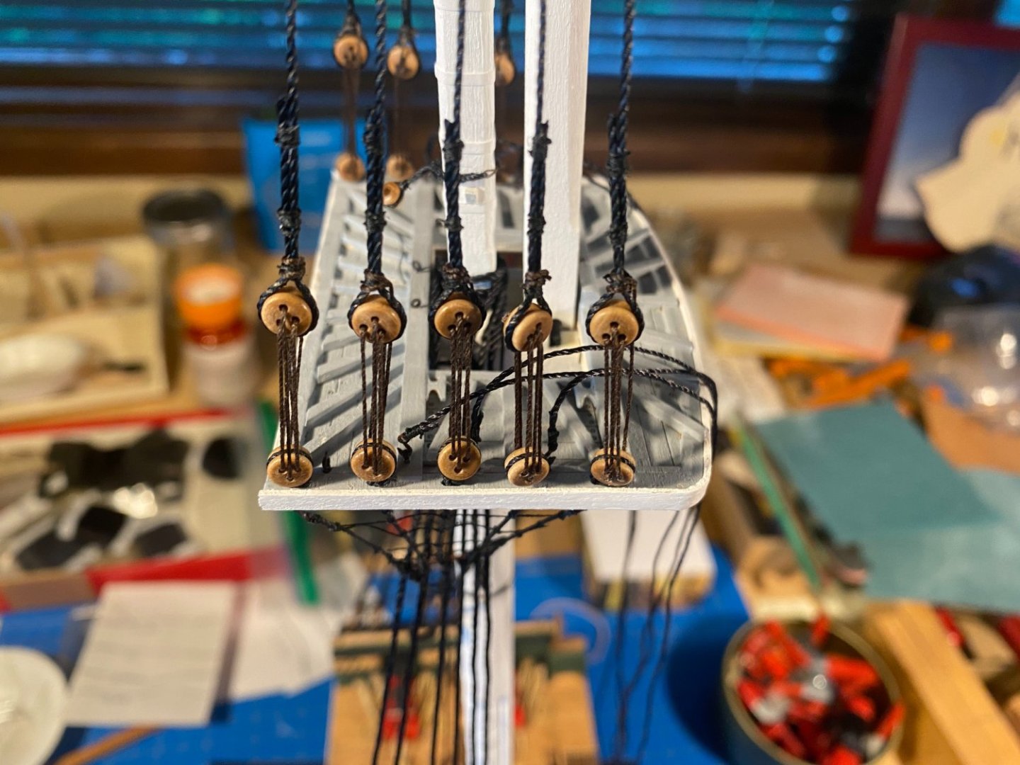
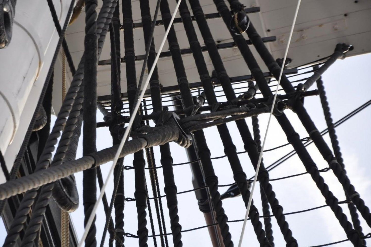
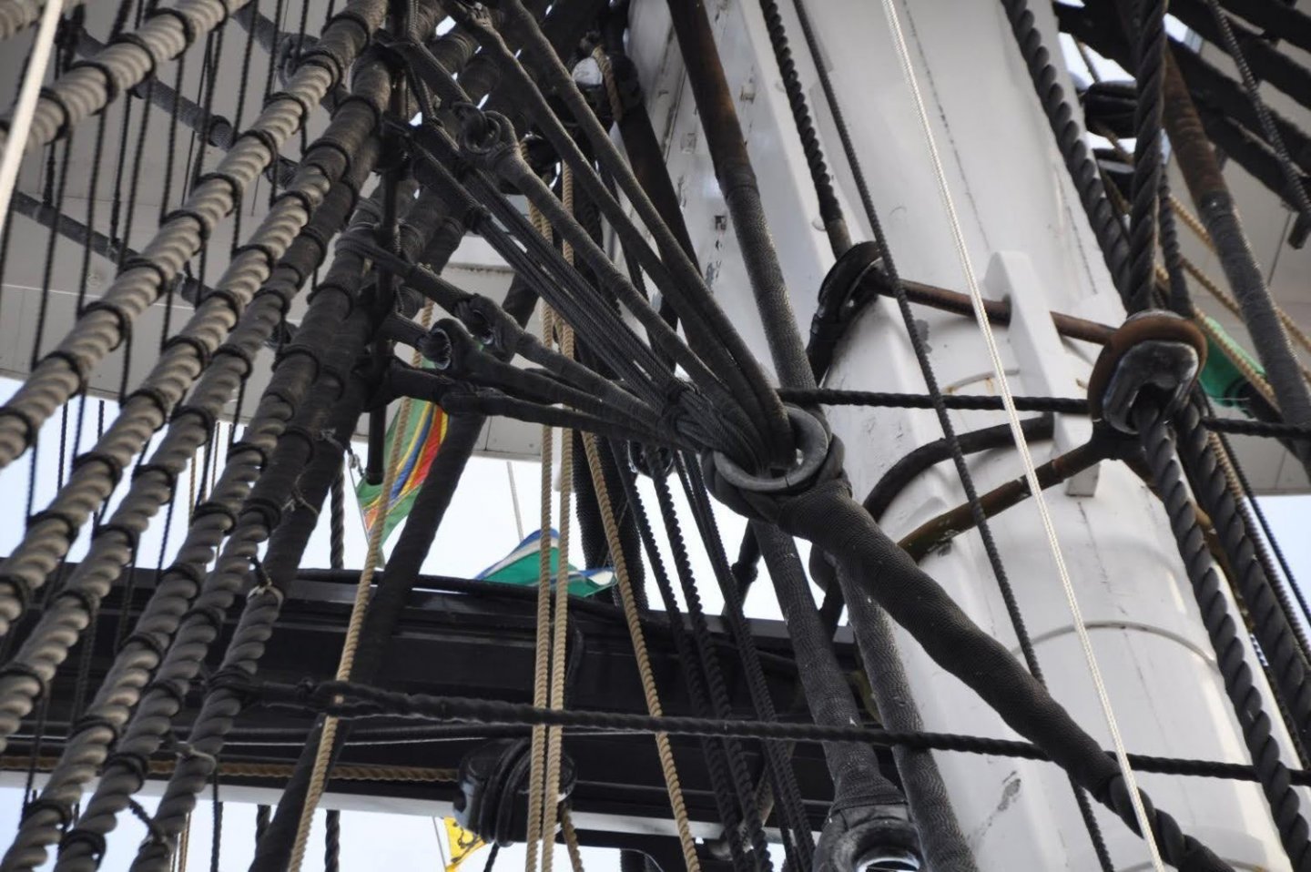
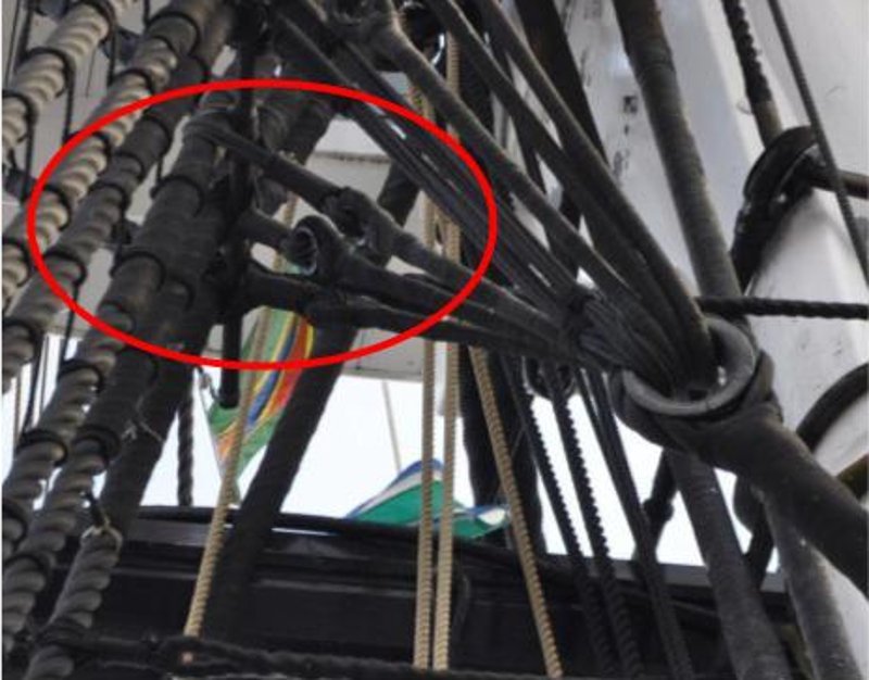
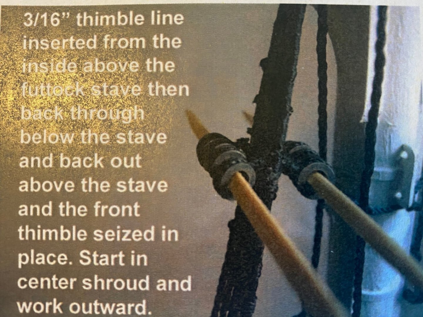
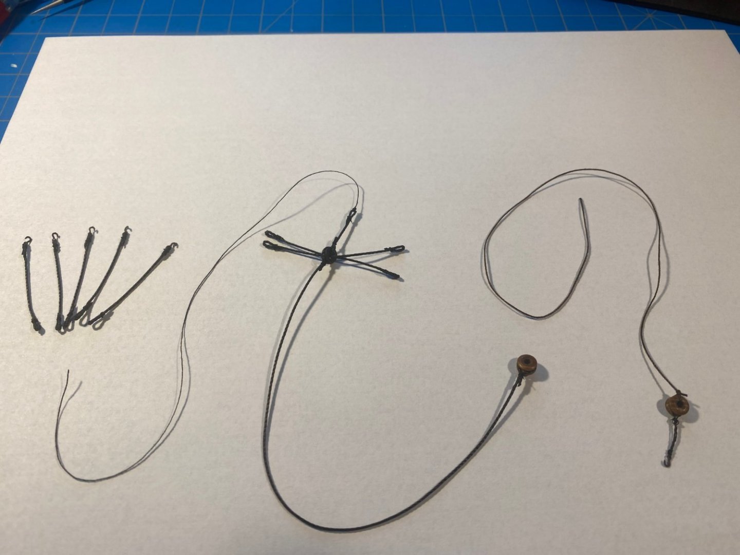
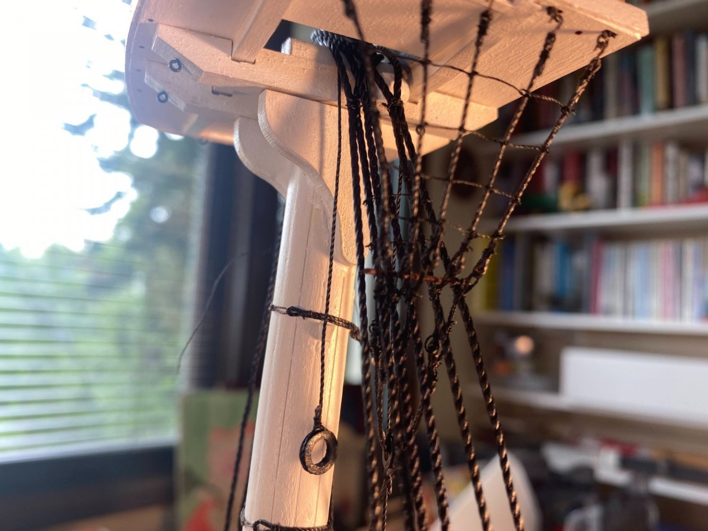
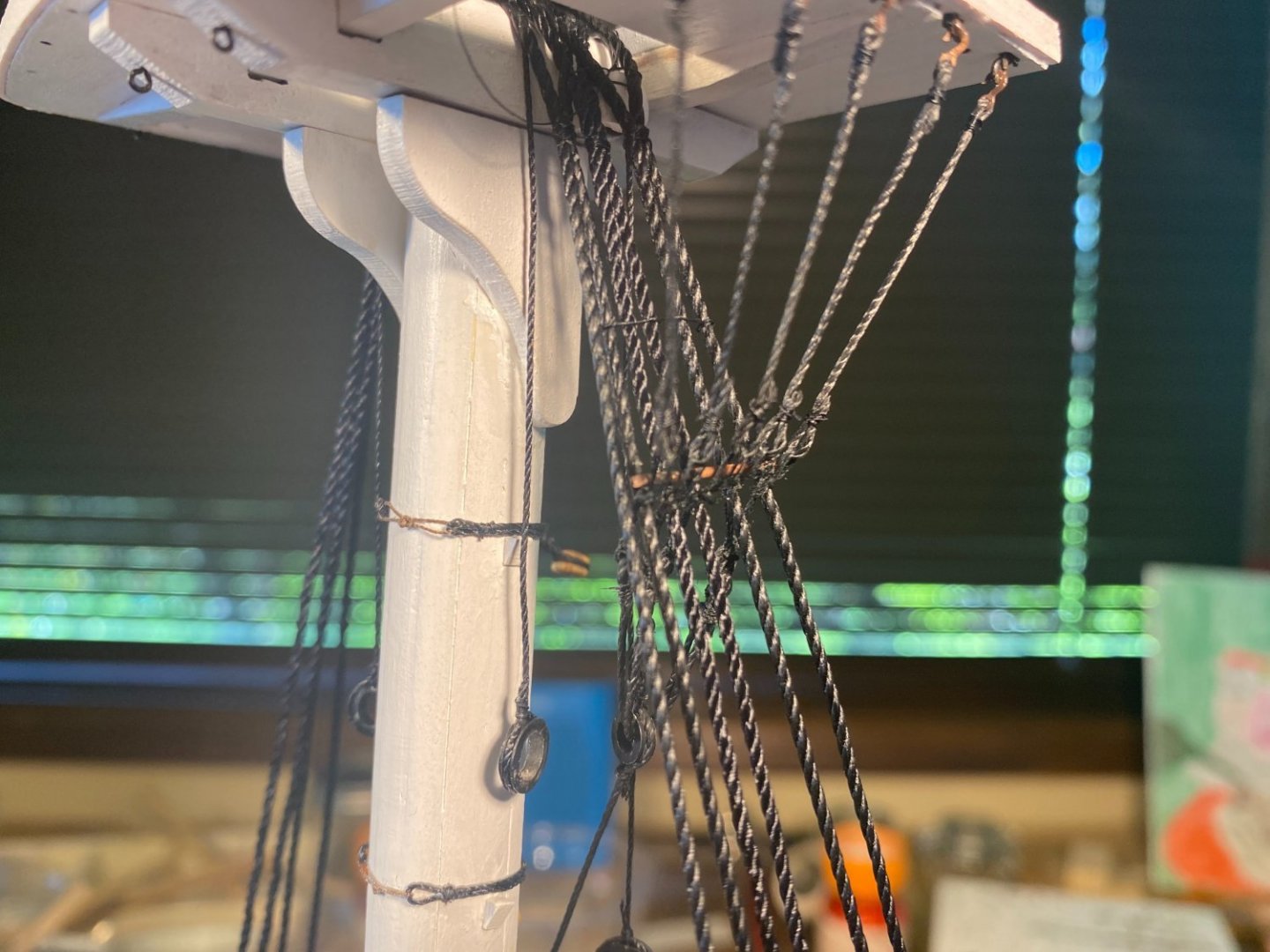
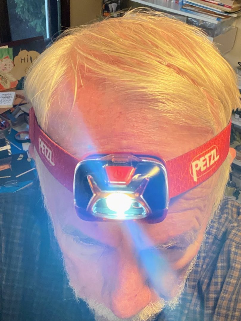
On each side, the futtock shrouds run from the eyebolts on the bottom of the fighting top (below the topsail shroud deadeyes), down to a ring at the top of the bentinck shroud. The bentinck shroud runs down from there across to an eyebolt previously installed (hopefully) in the waterway on the opposite side. The whole assembly is designed to secure the upper mast standing rigging (topsail, topgallant and royal shrouds) to the hull and not just to the fighting top. Back in February I expressed puzzlement as to the rigging of the futtock shrouds, especially where they intercept the lower main shrouds. Photos supplied by usedtosail and JSGerson were a huge help in getting me educated. Thank you. Each futtock shroud has three parts, an upper one hooked to an eyebolt on the fighting top, a lower one attached to the ring at the top of the bentinck shroud, and a middle one connecting the other two in the immediate vicinity of the main shroud. The middle part appears to be some sort of lanyard (adjustable standing rigging), and that is the way it is depicted in the instructions to MS’s full Connie kit. In the picture below it appears to have some sort of anti-chafing cover (probably a late 18th century equivalent to Kevlar). 😀 I don’t care much for this kit’s approach. It has large, circular thimbles seized just below the hooks at the upper end of the upper part, and on either side of the main shroud (the latter being the middle part). Because they are circular and too large, these thimbles do not look like anything on the real ship. The real ship does appear to have thimbles in these places, but they are tear shaped, not round, and they are small enough to be almost impossible to duplicate at this scale. Also, put together per the kit, instead of running a straight line with the bentinck shroud, the futtock shrouds would take an awkward, and unrealistic, jog at the main shroud, as seen in this picture in the instructions. There are a lot of parts to these shrouds. The picture below shows how I put them all together for the starboard side futtock shrouds (yet to be installed), after having a very difficult time rigging everything on the port side. From left to right are: 5 futtock shroud upper parts, with a hook at the upper end and a small tear shaped loop at the other end The bentinck shroud with (from top to bottom): the lanyard which will be the middle part of the center futtock shroud the lower part of the center futtock shroud a large ring, through which run two pairs of futtock shroud lower parts, with loops at each end, to which I will tie the middle part lanyards, and a bullseye seized at the lowest end The lowest part of the bentinck shroud, at one end of which is the hook which engages the eyebolt in the waterway, and at the other end a bullseye to which is tied the dark brown lanyard will be lash the two bullseyes together. Rigging this was a matter of lashing the lower part of each futtock shroud to the corresponding upper part, and that proved to be difficult and at times very frustrating. Rigging the first one (the center one) took me over 2 hours spread over 3 different attempts. The biggest part of the problem was being able to see clearly what I was working on, due in part to the fact that I wear monovision contacts; that is, one eye adjusted for distance and the other for closeup. They work amazingly well for just about everything (including biking and skiing). But for this closeup work and with multiple layers of rigging in front of me, I had difficulty getting my eyes to focus on the layer I needed to see. A big help was finding a very bright headlight stashed among some camping gear. With the lamp, perseverance, focus and some salty seaman’s language, I got the other four rigged in less time than it took to rig the first one. After finishing that task, I lashed the futtock stave to the main mast shrouds, then rigged a couple of ratlines on those shrouds so that the less courageous members of my crew (that would be me) can climb through the lubber hole in the fighting top. That rigging was also quite difficult since I had the futtock shrouds between me and what I was working on. One of the ratlines is missing in the second picture below -- the glue didn't hold well enough and it came untied from the shroud. ☹️ Finally I rigged some ratlines to the futtock shrouds, a task which was much easier than what had preceded it. So now moving on to doing it all over again on the other side. As can be seen from the picture of all the parts above, I rigged everything I could before attaching anything to the model, something I had not done the first time around. I will also lash the futtock stave and a couple of ratlines to the main shrouds before installing the futtock shrouds. All of this should make things a little easier. I admire those of you who have built models of the entire ship . . . I only have to do this twice, and you have done it six times!

- 163 replies
-
- 4
-
-
-
- Model Shipways
- Constitution
- (and 2 more)


.JPG.2c082ed65b29c19d437c2ff9367457b0.JPG)