HOLIDAY DONATION DRIVE - SUPPORT MSW - DO YOUR PART TO KEEP THIS GREAT FORUM GOING! (89 donations so far out of 49,000 members - C'mon guys!)
×


Tomculb
-
Posts
345 -
Joined
-
Last visited
Content Type
Profiles
Forums
Gallery
Events
Everything posted by Tomculb
-
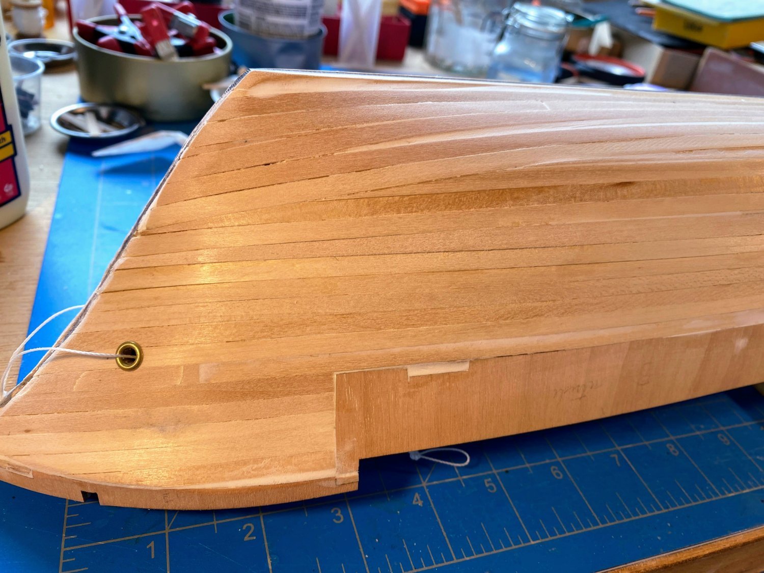
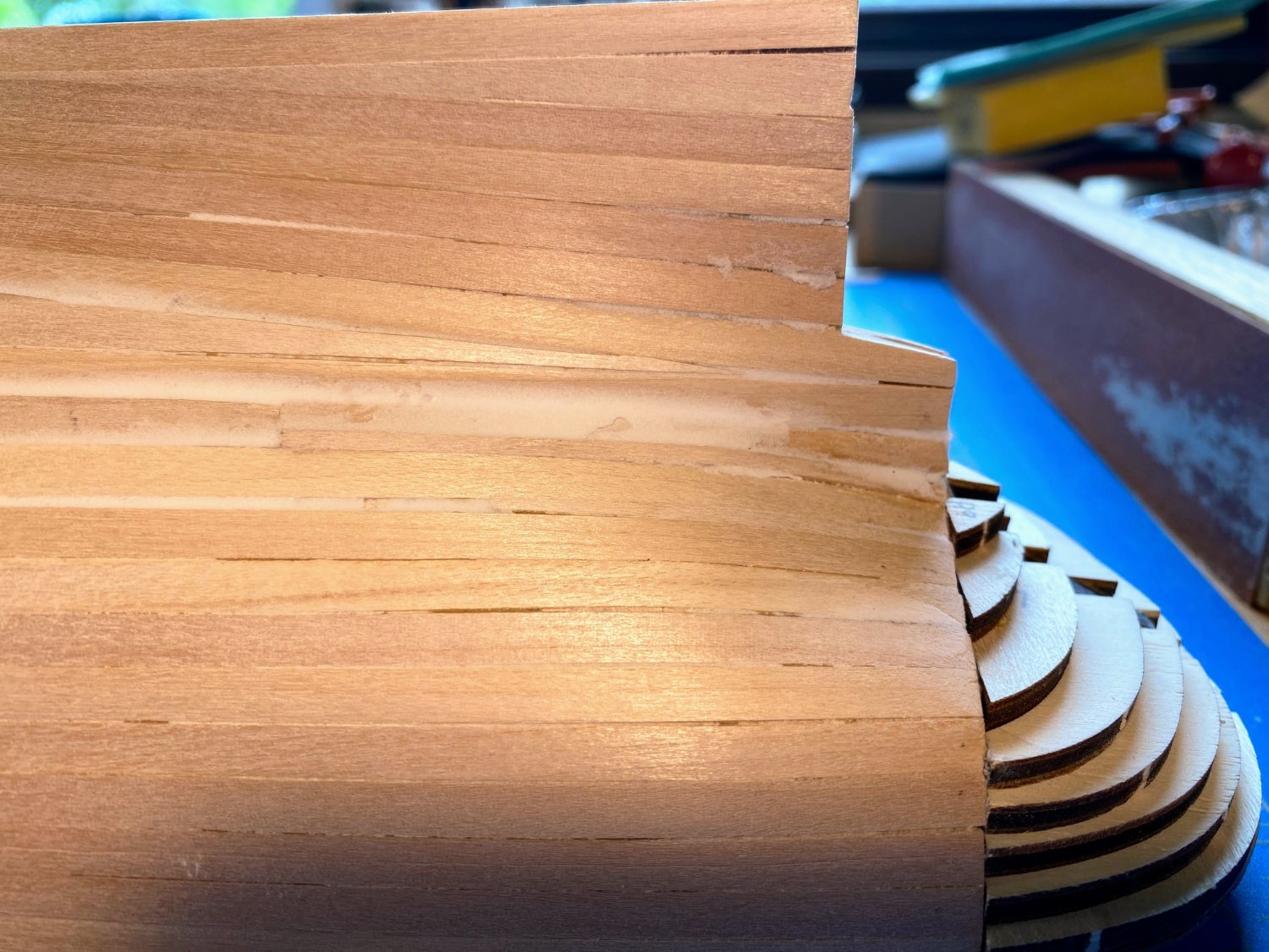
 First a moment of joy in memory of Jimmy Buffet. Not joy that he just passed away of course, but the knowledge that he would have wanted his passing to be memorialized by a raucous party. RIP Jimmy. Hull planking is now complete. At least I hope it is; as mentioned previously, it’s my hope to use just one layer of planking, and to hide all the flaws with a lot of sanding, filler and paint. As you can see in the photos below, when I got bored with laying planks, I did some sanding and filling, so the result at this point is a mixed bag of rough and a little bit less rough. The challenge with this build will be disguising the plywood bulwarks. I have some hope there, since if I close my eyes and run my fingers over the transition from plank to ply, I can’t feel it. Do the same places where the things look pretty smooth and I can definitely still feel the planks. I have a great deal of admiration for Chuck Passaro and his followers . . . those who are able to plank a hull precisely, smooth it with a little sanding, and leave it unpainted, a display of great craftsmanship.
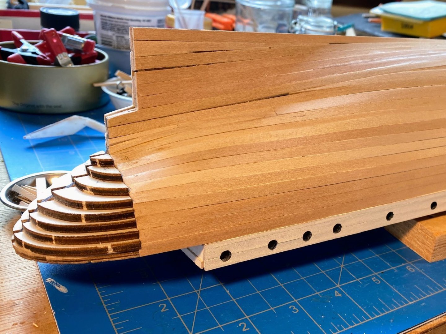

- 206 replies
-
- 6
-

-
- Endurance
- Shackleton
- (and 2 more)
-
Masking tape for curves .
Tomculb replied to LEGION 12's topic in Painting, finishing and weathering products and techniques
Tamiya makes masking tape for curves, in various widths. I've seen it on their website and also on Amazon, maybe other places as well. -
Thanks Josh for letting me know I'm not as oblivious as I thought I was. 😁 Last night I finished planking the hull. I'll get some photos and a post on my log within the next few days. I'm hoping to leave it at one layer of planks, using a lot of sanding, filler and paint to hide all the blemishes. Regarding glue, I've always used carpenter's wood glue almost exclusively. I have often used a moderate amount of pressure (along with some water & heat induced bending) to hold pieces in place while the glue dries, and I've never had a plank spring loose. My oldest such hull is 30+ years. At least that's what has worked for me.
-
Josh, I don't know how the heck I overlooked your name, in your signature block of all places! And thanks for the info on where to find stanchions. Tom
-
Theo. . . (or whatever name you prefer) I am in awe of the work you have done while I’ve been largely absent from my shipyard. I am delighted you found some use for some of my thoughts and ideas. I have gotten so much out of these boards and the contributions of others, far more than I have contributed, but it’s nice to know I’ve contributed a little. I still haven’t caught up with all the posts on your log, but I’m getting there. Maybe I missed this in your log, but where did you find the stanchions you used to replace those supplied by OcCre? I am close to finishing the rough planking of the hull, but you’re way ahead of me on other parts of the ship, and it won’t be long before I’m using your innovations and ideas. Keep up the good work. PS . . . I see you’re a fellow Washingtonian, but on the opposite side of the state. We’re fortunately more than a dozen miles or so from what was the worst of the fires, but we’ve been buried in smoke. Raining today, which is good.
-
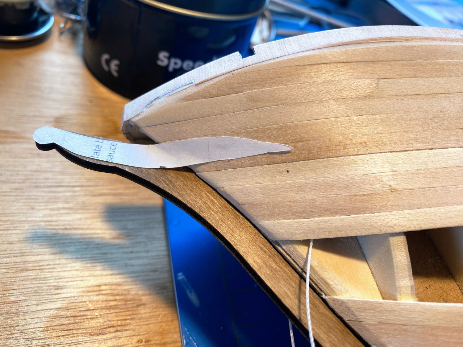
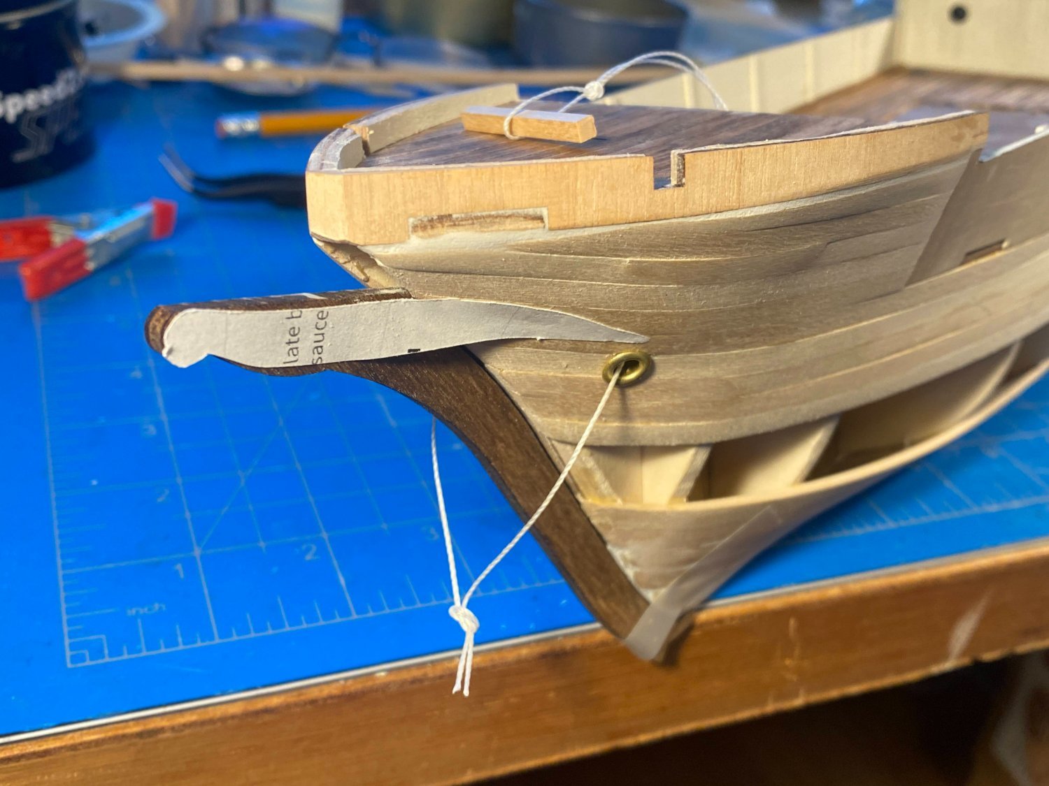
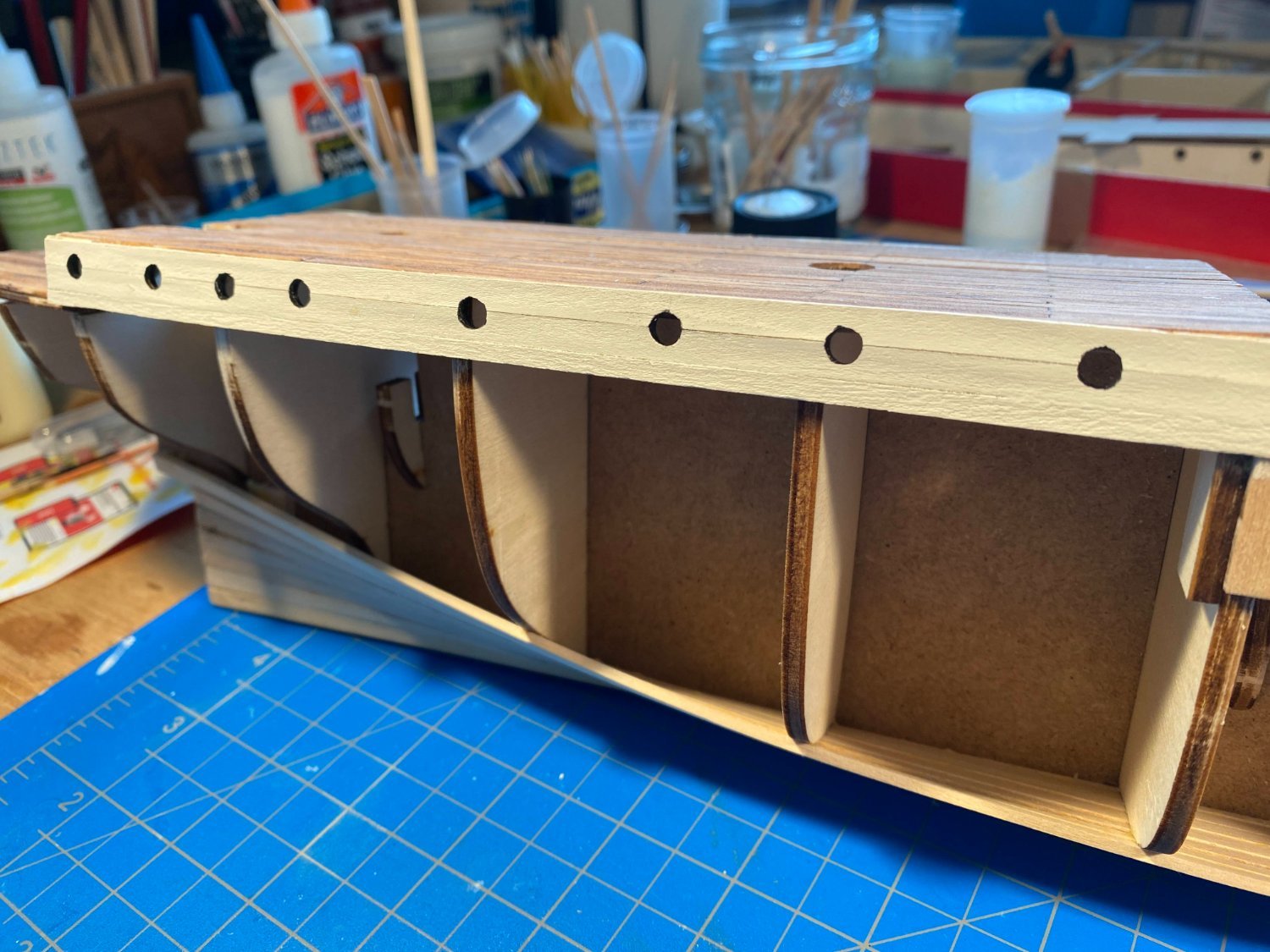
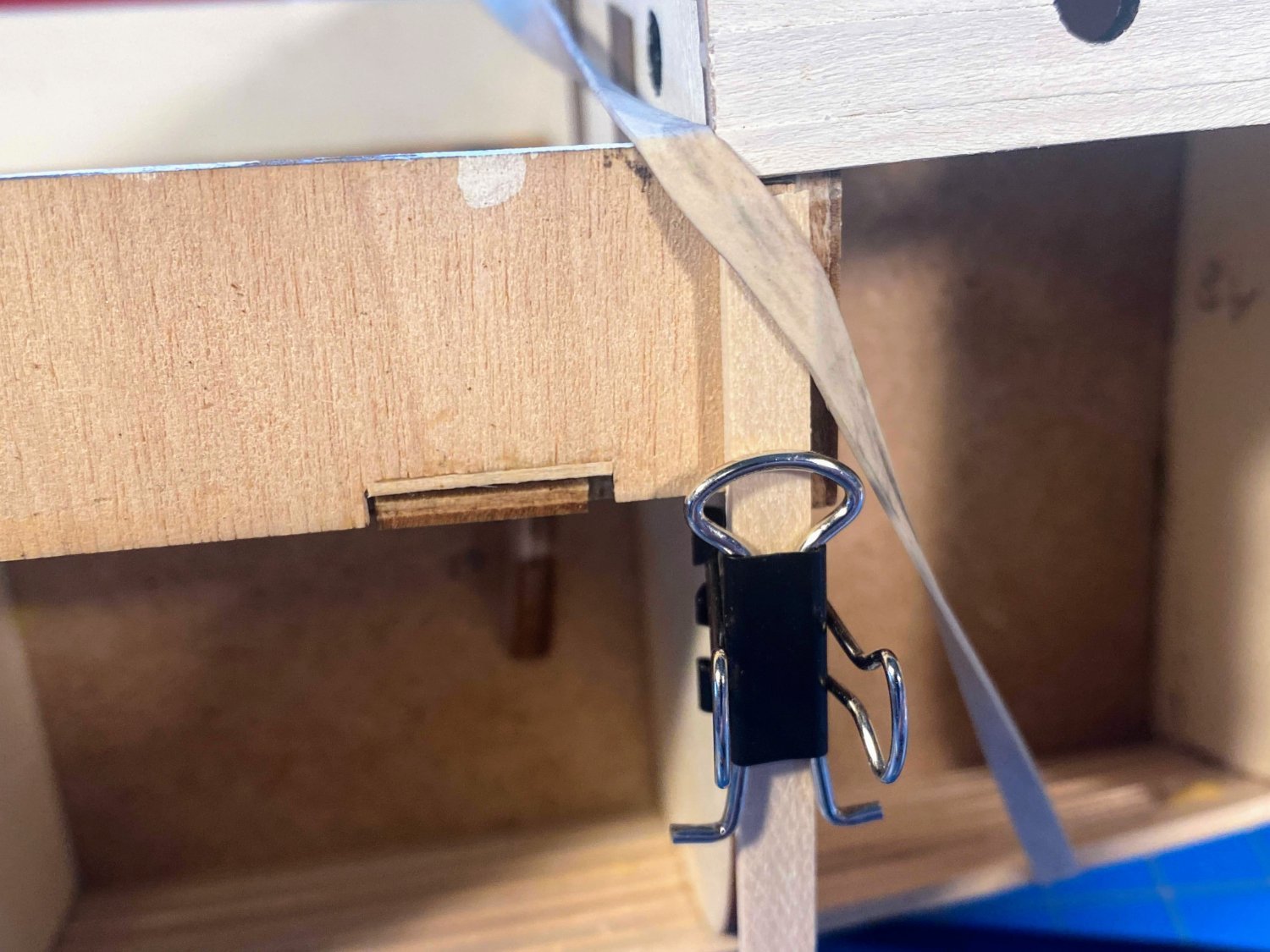
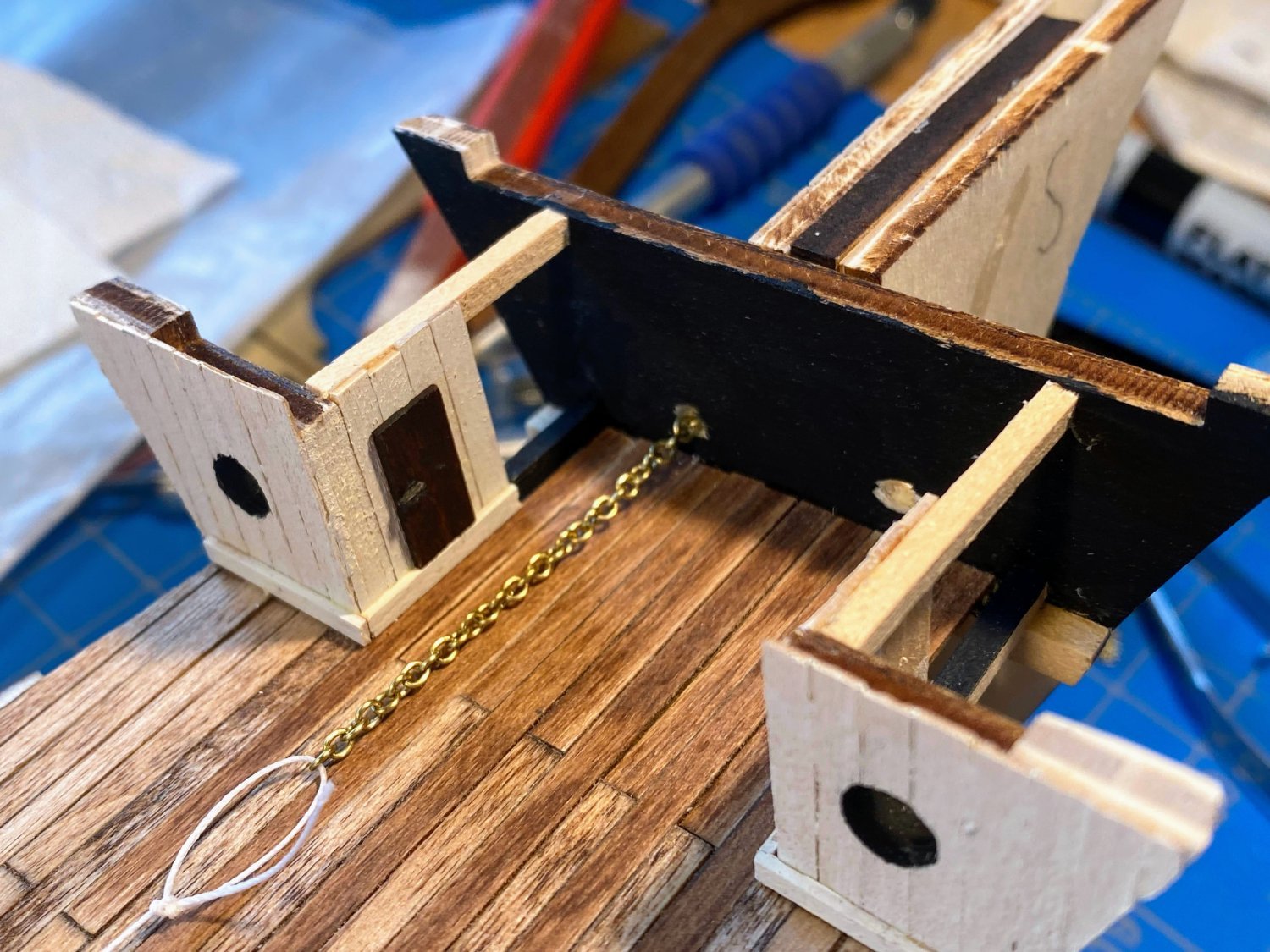
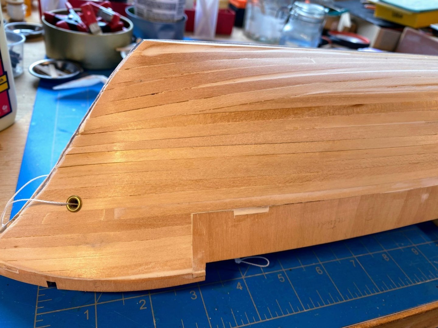
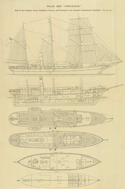
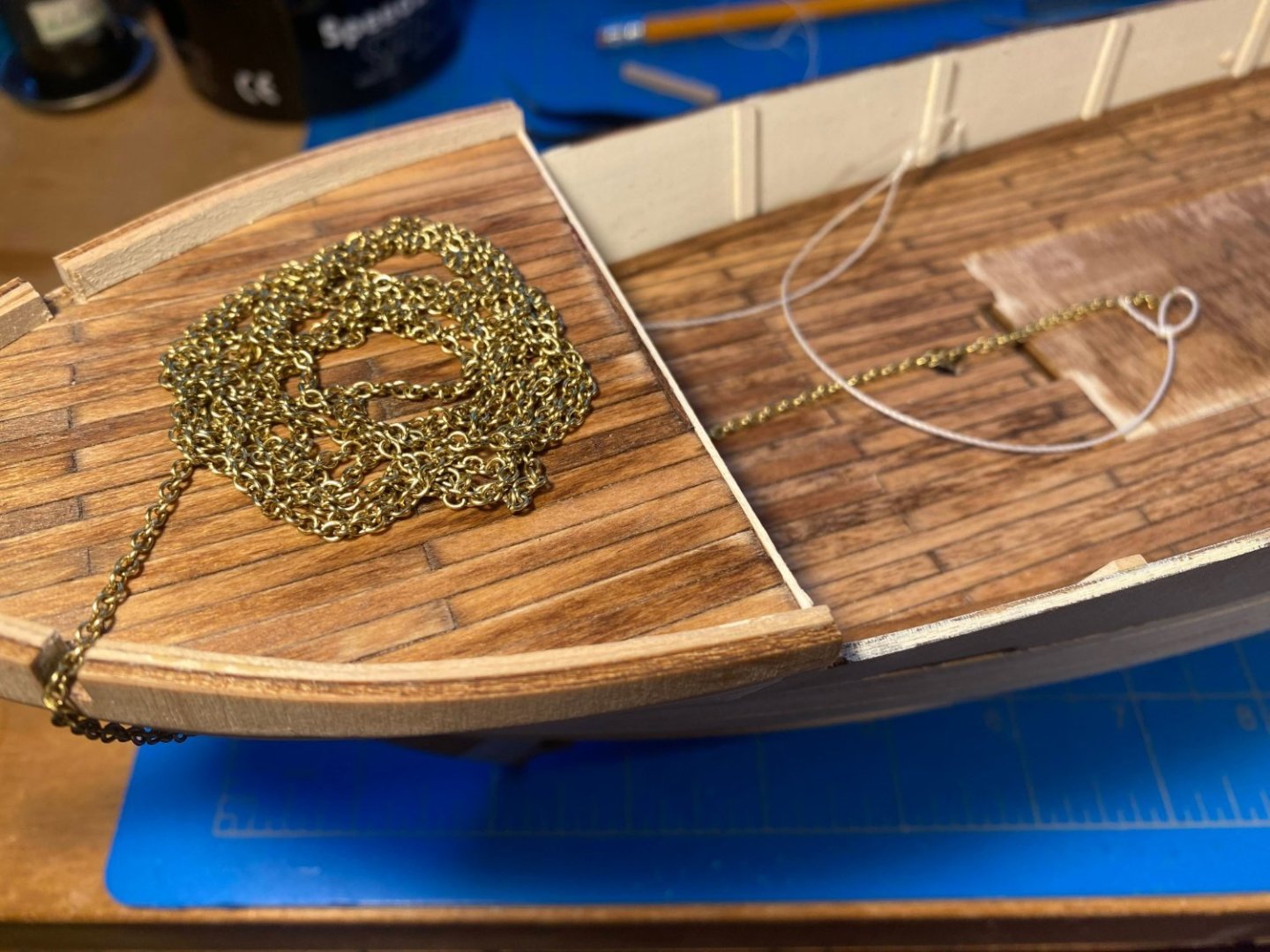
The wonderful distractions of summer (not the least of which is our daughter’s wedding) have slowed progress in the shipyard considerably. I’m certainly not complaining, just explaining. Don’t expect my next post anytime soon. Hull planking is maybe (optimistically?) about 2/3rds finished, and there are only a couple of things worth mentioning. The instructions have you do most of the planking with a single, bow to stern, strip of wood, which I did when doing the lower half dozen planks. But I decided that was a bit unwieldy. I added wood to the middle two bulkheads, and I am doing the rest of the hull with half length planks, alternating where the two half length planks meet. Much easier. As I think I mentioned previously, the first layer strips provided by OcCre are 2mm thick. I have a bunch of 1/16th thick strips lying around, and I experimented bending those, and found the difference (1/16” is thinner), while small, to be noticeable when it comes to bending and twisting. So while the lower hull half-dozen planks are 2mm, the rest of the hull is 1/16", which means I’ll have a bit of sanding to do where the two sizes meet. But I have a lot of sanding to do all over the hull, so that’s nothing new. I sanded and filled (using spackle) the first couple of inches or so of the bow, and then drilled holes for the hawse pipes. I had to determine where the hawse pipe holes were to be located, something that would have been easier with kit plans rather than just pictures. The instructions direct drilling the hawse pipe holes 30mm below the white rub rail that runs the length of the hull just below the top of the bulwarks, which meant determining where that rub rail should be. The ship’s plans I found online show a rub rail quite a bit lower than where OcCre locates it, below the trailboards, and with the hawse pipe just below that. Thinking OcCre got it wrong, I took a look at my Frank Hurley book, and found the color photo shown below. Clearly something changed by the time Endurance reached the ice, and that’s what OcCre depicts. With the location of the rub rail determined, I decided 30mm below that was far too low for the holes. Instead I cut out a paper outline of one of the trailboards, and used that as a reference point to determine (somewhat randomly) where I wanted the holes to be. I also gave myself a bit of a challenge. I want the anchor chain to run continuously from the anchor stocks, through the hawse pipes, through the holes I drilled months ago in the forward bulkhead, around the windless to be installed in the open area below the forecastle deck, then through the holes I drilled in the deck just aft of the windless. No particular reason to make the chain run continuously in a model (a gap inside the hull would never be seen), but it just seemed kind of fun to try this challenge. Before I had more than a plank or two of the upper hull done, I ran the piece of thread seen in the picture above through the holes in the bulkhead. Then after the bow was significantly planked, I drilled holes for the hawse pipes, with a bit of difficulty ran the thread through those holes, and dry fit the hawse pipes in place. I then pulled the chain through and determined that it worked!


- 206 replies
-
- 8
-
-
- Endurance
- Shackleton
- (and 2 more)
-
Thanks for the offer Joe. When you say "full size", I'm assuming you mean model size, not ship size, as the latter would be huge. Where did you find them?
-
Welcome to the Endurance crowd Will. Your progress looks really good, especially the deck planking. I haven't posted in several weeks, since summer has provided me with too many tantalizing distractions away from the shipyard. I started another post about two weeks ago, but I've been too distracted to do even that. Short report is that I'm still planking the hull. Looking forward to following your build.
-
Very well done François. I'll be referring to your log frequently in the many months ahead as I slowly make progress on my build. Thanks for showing the way.
-
Sure glad to see MSW back from the dead. I have done some additional computer sleuthing regarding Endurance. First I found some amazing “remastered” video of Endurance departing on its voyage, in the ice, breaking up and losing its mast. https://www.youtube.com/watch?v=gqJDqjS8RLE https://www.youtube.com/watch?v=BJ-6RJkuLlQ So amazing in this age of AI that I wonder what “remastered” means and how real the videos are. I also discovered my ability to temporarily download books from our public library, and I downloaded The Ship Beneath the Ice, the recently published book about the discovery of Endurance on the Antarctic sea floor a little over a year ago. I was most interested in photographs of the hull, and was disappointed. There are only a handful of pages of photos in the book, and most of those are of the recovery effort. I don’t think there are any of the ship that I had not seen previously elsewhere. I understand there is a documentary film in the works, and I wonder if for some reason they are holding back photos and videos of the wreckage until after the release of that film. The only thing of real interest to me in the book was a drawing by the author that gave names to the decks. From bow to stern: Fo'c'sle Deck, Main Deck, Poop Deck and Well Deck. I don’t know whether those are just labels made up by the author, or whether they have some legitimacy, but I think I’ll start using them. Meanwhile I’m back to work on planking the hull. Nothing worth taking a picture of yet.
- 206 replies
-
- 3
-
-
- Endurance
- Shackleton
- (and 2 more)
-
Thanks Johnny for your observations and suggestions. I didn't think of planking the inside surfaces of the bulwarks, but it's a great idea. Unfortunately with the stanchions already glued in place it becomes a much more difficult endeavor, and I think I'll pass on that. I'm enjoying following your Wasa/Vasa build. Back in the late 60s my parents took my brother and me to Europe, including a stop in Stockholm, and I still remember a visit to see the Vasa. As I recall, there wasn't a lot of it to see then. One of my many bucket list items is to see it again and see what 50+ years of restoration has done.
- 206 replies
-
- 2
-
-
- Endurance
- Shackleton
- (and 2 more)
-
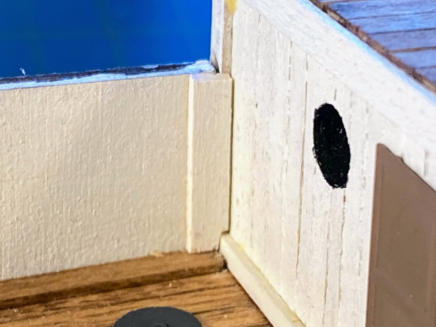
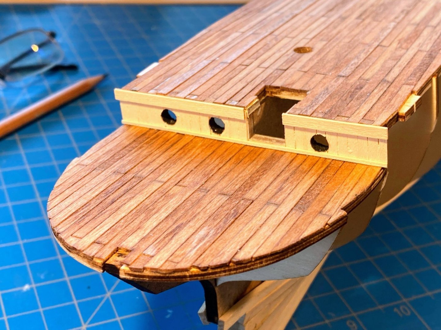
Running along each side of the deck in the bow are short rails or bulwarks (I’m not sure what to call them) consisting of a laser cut piece on either side, lined with a 2mm x 5mm piece trimmed and glued on the inside of each. I found bending the laser cut pieces to be quite challenging, since they are cut from plywood. There is a cutout on each for the cathead, and the pieces are weaker at that point. I fractured one there and had to glue it back together and then try to bend it very gingerly. Solid pieces of basswood would have been easier to work with. After that experience, rather than use the supplied wood to line each side, I laminated four pieces (two layers) of 1/32” x 3/8” on the inside of the laser cut piece. Rather than use one piece the length of each side and then cut out a gap for the cathead as the instructions direct, each layer consisted of two pieces, separated by the gap for the cathead. This all went together quite easily. Finally I shaped a piece for the stem, and cut and glued on the deck a couple of short pieces at the bow, again as instructed. The instructions show a white strip running along the lower deck on each side where the deck meets the bottom of the bulwarks. A white strip was not consistent with anything I’ve seen in the Hurley photos, and I thought a stained strip would be more common for a margin plank or waterway. As a touch of detail, I used a pencil to mark a couple of butt joints on either side. Using a single strip of wood for each of these pieces may not have been the best approach. It was difficult to place them without smearing glue where I didn’t want it, and holding them in place against the bulwark with my fingers while the glue got tacky enough was difficult. Unfortunately I left a millimeter gap along part of the port side, which I refrained from photographing. Fortunately the gap is not all that noticeable unless you look at it from just the right angle. I then added seven bulwark stanchions on each side.


- 206 replies
-
- 6
-
-
- Endurance
- Shackleton
- (and 2 more)
-
The kit comes with laser cut pieces for the sides of the hull with eight port holes in each of them. As I did with the bulkheads, I enlarged the portholes to look more like those on the ship, this time using my Dremel tool and a conical shaped bit. That was much easier than the drill bits I used to enlarge the bulkhead portholes. The instructions have you plank these pieces (horizontally) quite a bit later in the build, but I decided to do that now, using .6mm x 5mm supplied strips. I also painted them white (with black on the inside edges of the portholes) before gluing them in place, rather than waiting until later. They fit well with a minimum of bending and twisting. The bulwark pieces are also laser cut, and they were a little more challenging. I made the job a bit more problematic when I installed the lower deck without noticing a pronounced downward bend in the deck at the aft port corner. A small shim in the notch in the bulkhead piece took care of that problem. Similarly I could not make the tab at the upper forward corner of the bulwark pieces fit into the notch cut cut in the laser cut bow “railings” (I can’t think of a better word for these pieces), so I filled those notches with small pieces of wood. Moving from aft to forward, these pieces have quite a bit of inward bend and outward twist (about 30°). As I did with the hull planks I have installed, I used water and my small iron to facilitate the bending and twisting. I also painted the inside surfaces of the bulwarks white before gluing them in place. The instructions would have you do the painting later, taping the decks to avoid getting paint on them.


- 206 replies
-
- 5
-
-
- Endurance
- Shackleton
- (and 2 more)
-
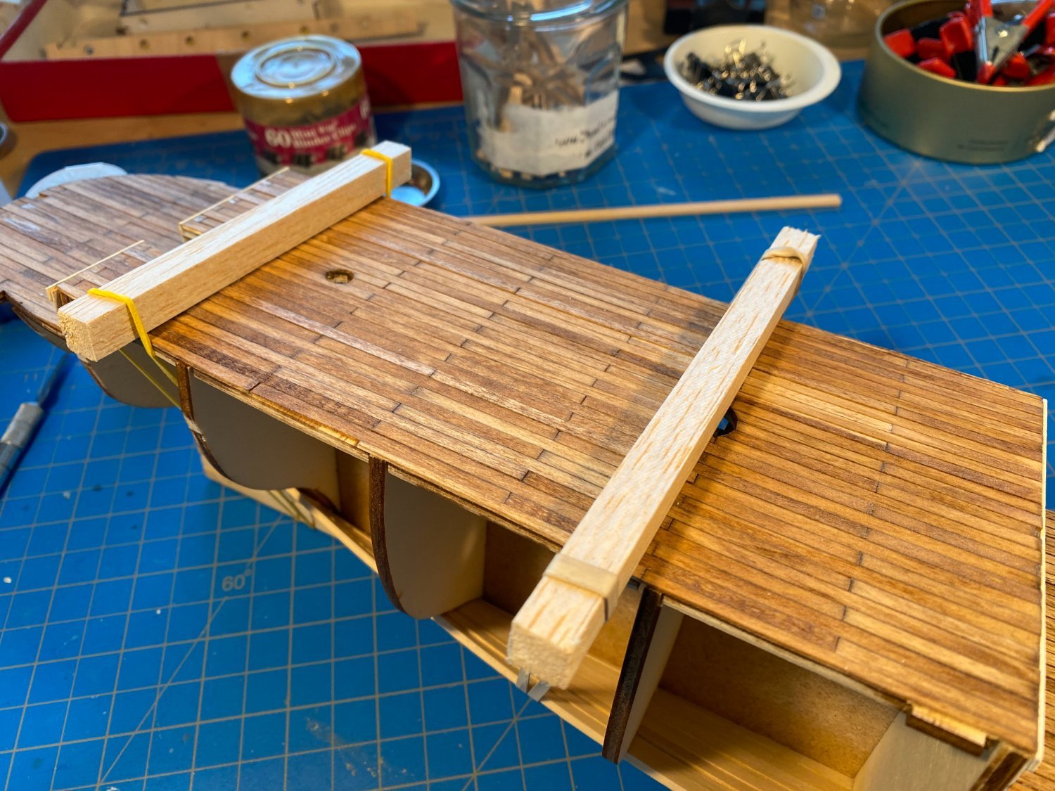
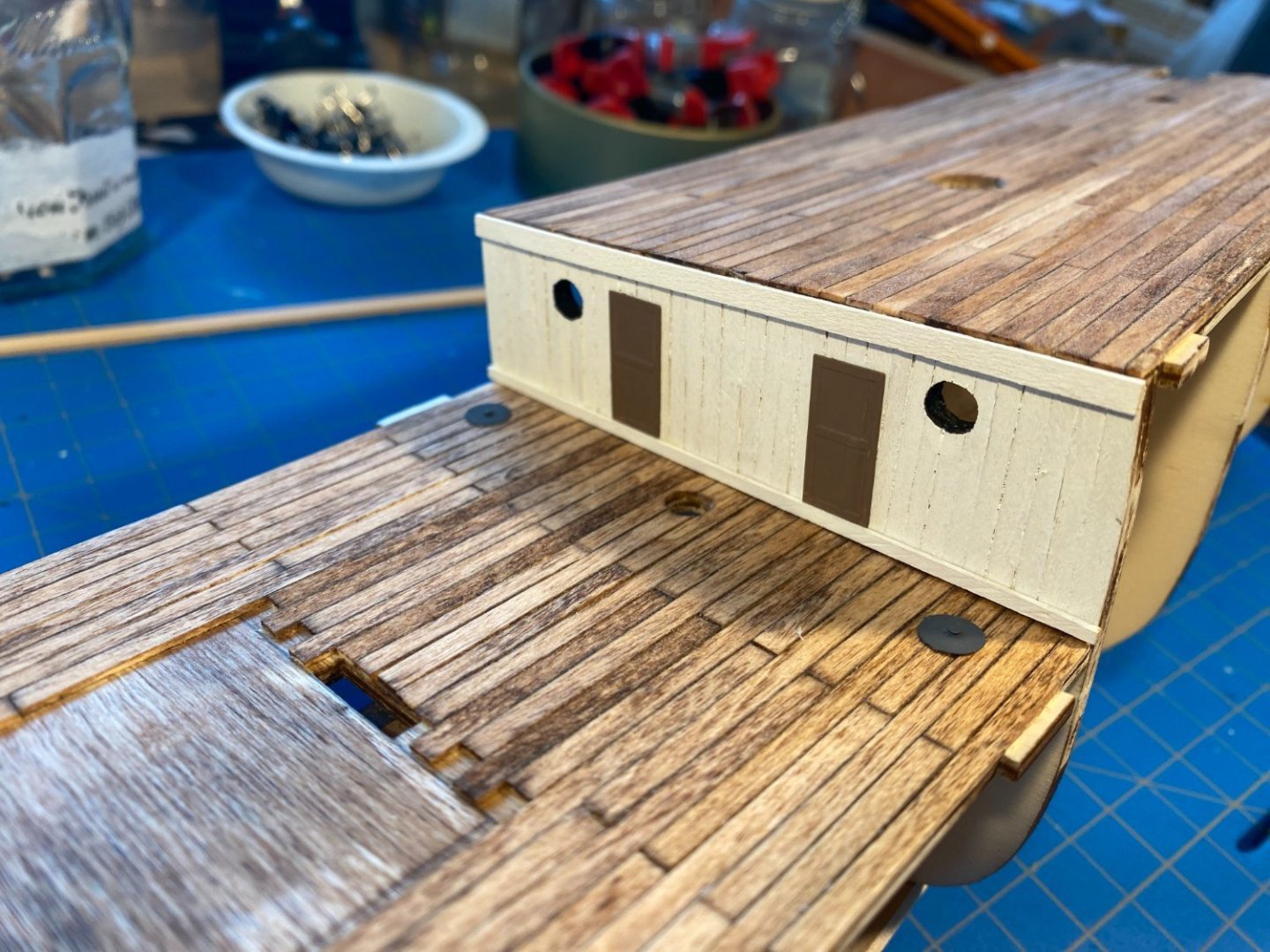
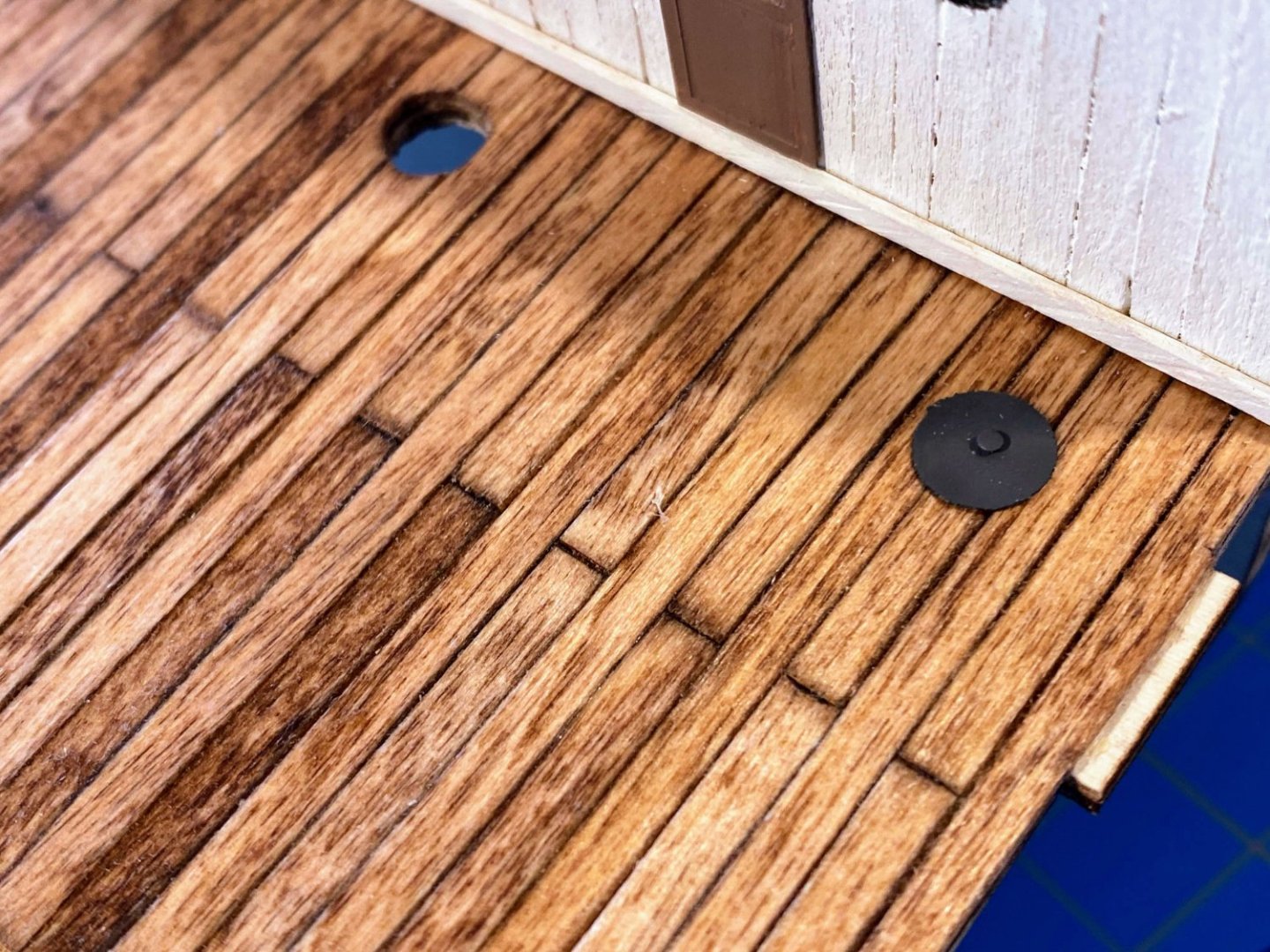
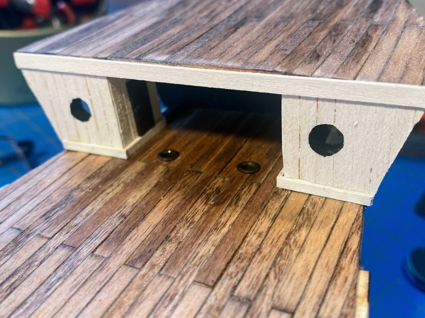
Gluing the remaining decks in place was pretty straightforward. The only “issue” I had was that the upper deck was a little warped, and I needed to use strong rubber bands looped around the hull and ⅜” square stock to hold it in place while it dried. Incidentally, does anyone know the correct terminology for the decks, if there is any? I know a quarter deck was usually the raised deck at the stern from which the captain ran the ship, but that doesn’t really describe these decks. Several weeks ago Clearway and I exchanged posts about how none of the plans show the vents or stacks OcCre would have you install at the aft end of what I have been calling the lower deck. His thought is that there should be capped holes there through which coal is loaded into bunkers. That makes a lot of sense to me. I made the caps with a three hole punch, using thick paper/thin cardboard from a manila file folder, painted dark gray. The little knobs are the heads of tiny nails pushed through the middle of each one. The doors are photo etched-brass parts, and for the moment they are temporarily held in place with double sided tape while I try to decide what color scheme I want for those parts of the ship not stained and not painted black or white. Unfortunately I haven’t seen any Hurley photos that are helpful. OcCre supplies dark wood for the outer hull planking and for trim elsewhere, and the photo/instructions show a lot of things (dog kennels for instance) painted dark brown. My initial reaction to the contrasting white and dark colors is that it looks too much like a yacht and not enough like a work boat, but that’s just me. But I do think I want something that looks a bit weathered. I ordered three shades of brown paint and what you see below is the lightest one. But I’m not convinced that’s what I want. In any event, the jury is still out on this matter.

- 206 replies
-
- 5
-
-
- Endurance
- Shackleton
- (and 2 more)
-
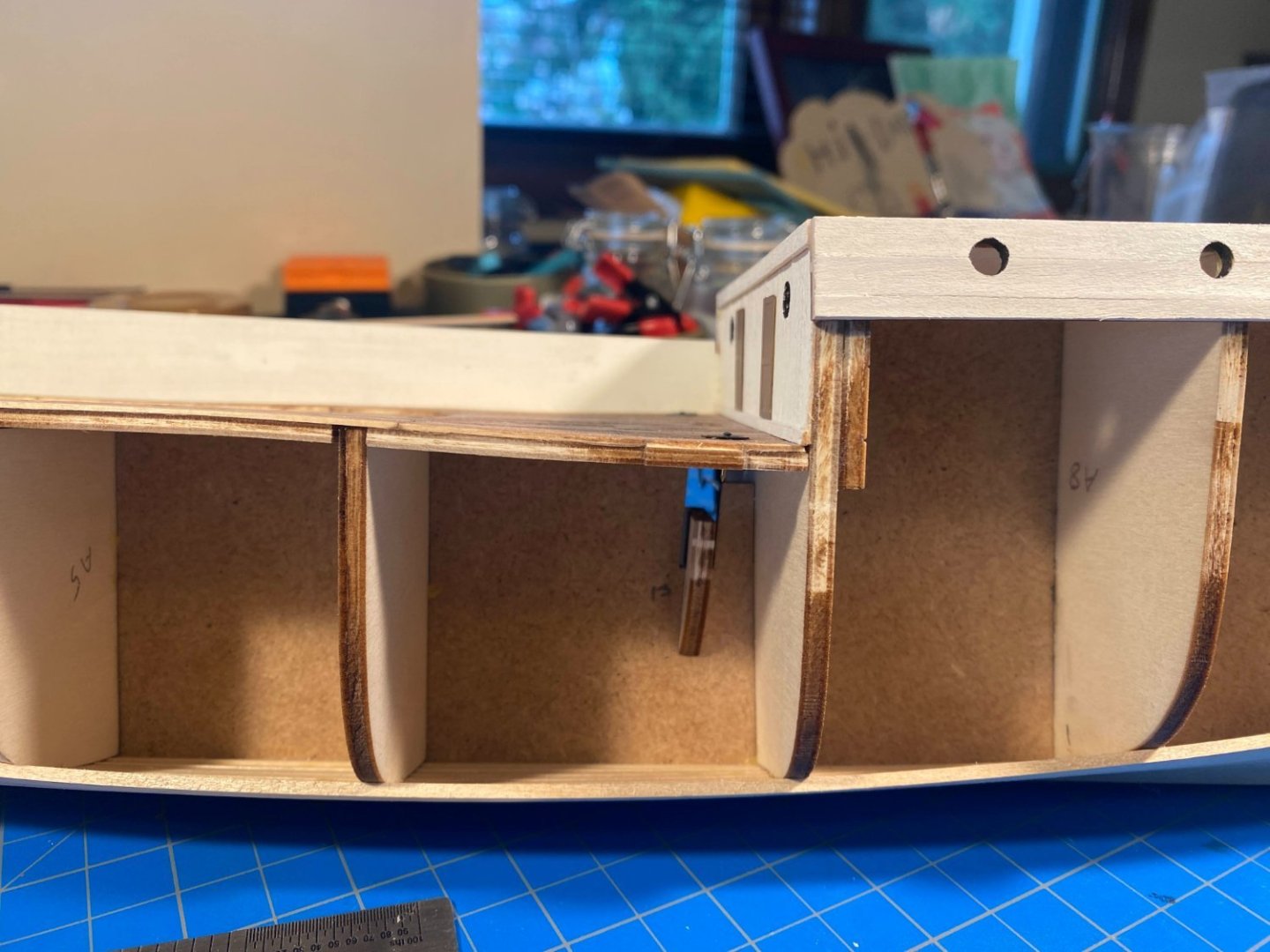
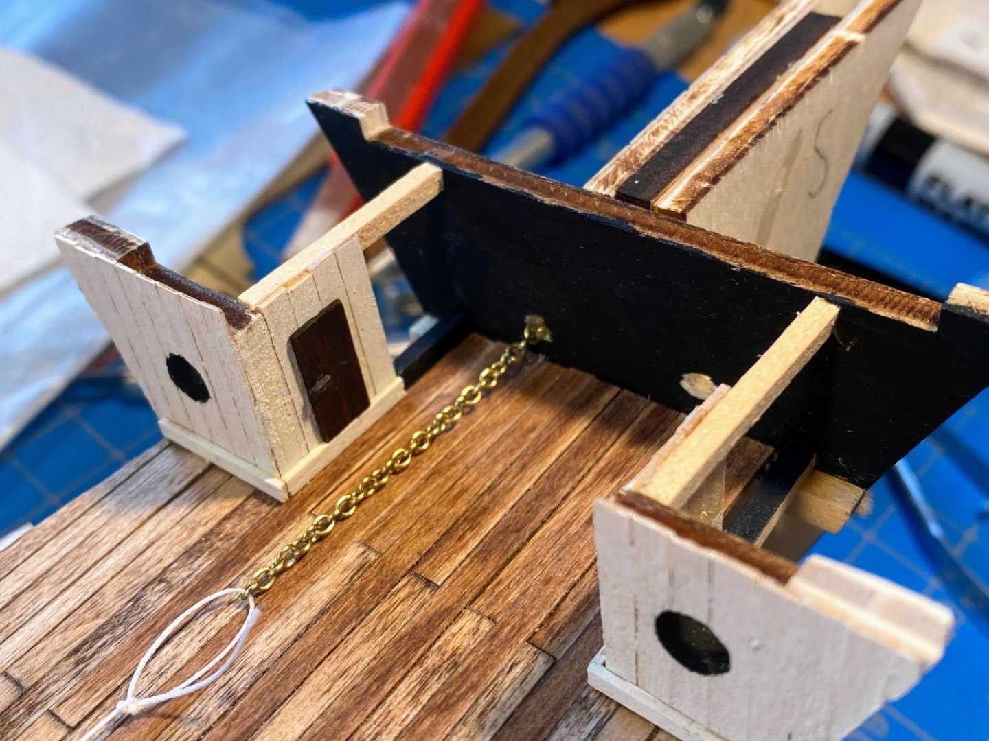
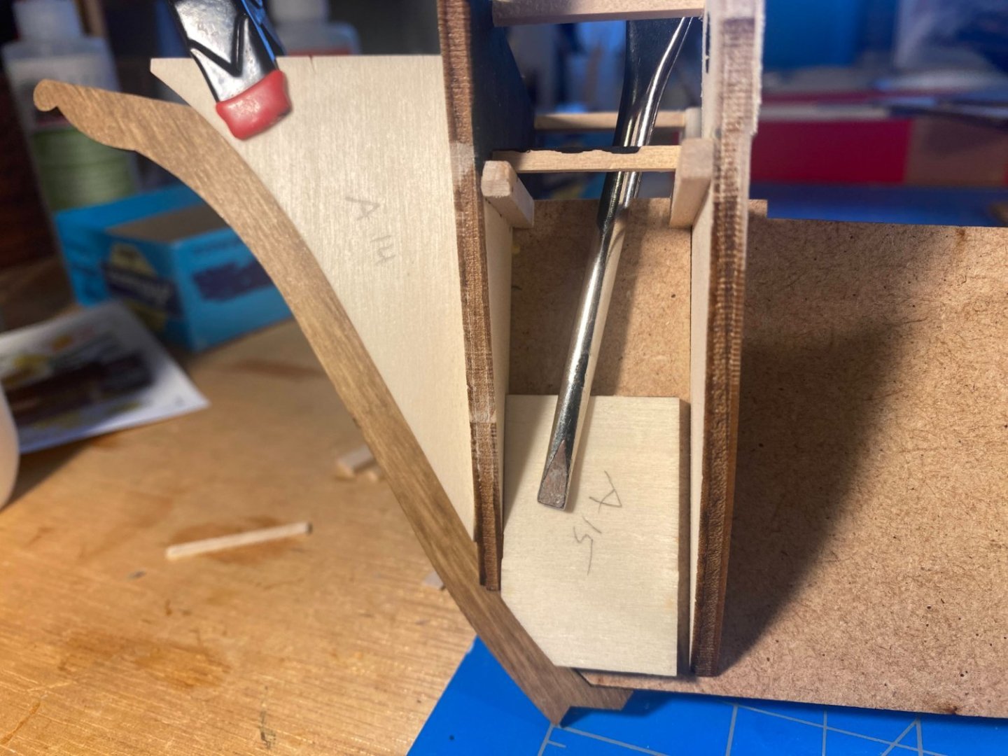
Leaving aside hull planking for now, I did the following: Glued the lower deck in place Extended the planking on that deck into the open space below the foredeck Planked walls for the W/C on the port side and the lantern locker on the starboard side (more on this later) Added trim where the bulkhead and the newly added walls meet the deck Made doors by gluing two 1/32 x 1/8 strips side by side, painted them brown, added tiny door handles painted black (which are barely visible), and glued the doors to the walls Drilled holes in the forward bulkhead, when it occurred to me that the anchor chains will pass through the hull through hawse pipes, pass through these holes in the bulkhead (a bulkhead that did not exist on the ship), and then pass aft to a windlass yet to be installed in this open area Drilled holes in the deck a little forward aft of where the windlass will be, and lined them with a couple of the fittings I will not be using to line the portholes. The chain coming off the windlass will drop into the chain locker through these holes. Glued the foredeck in place Trimmed the upper edge of the bulkhead/foredeck with a 1/32 x 1/8 strip The plans I previously posted and similar ones I have seen reflect a W/C and locker that appear considerably smaller than the ones I have built. I don’t see how that can be done with a bulkhead, portholes and open area as they appear in the Hurley photos. And as for the doors , , , that is pure historical speculation on my part. But I think they look credible. I cut the doors 16 mm high, which translates to 3’8” on the ship, requiring a major stoop to get to the head. Similarly, I don't see a chain locker anywhere on the plans, but it has to be directly below the windlass.
- 206 replies
-
- 4
-
-
- Endurance
- Shackleton
- (and 2 more)
-
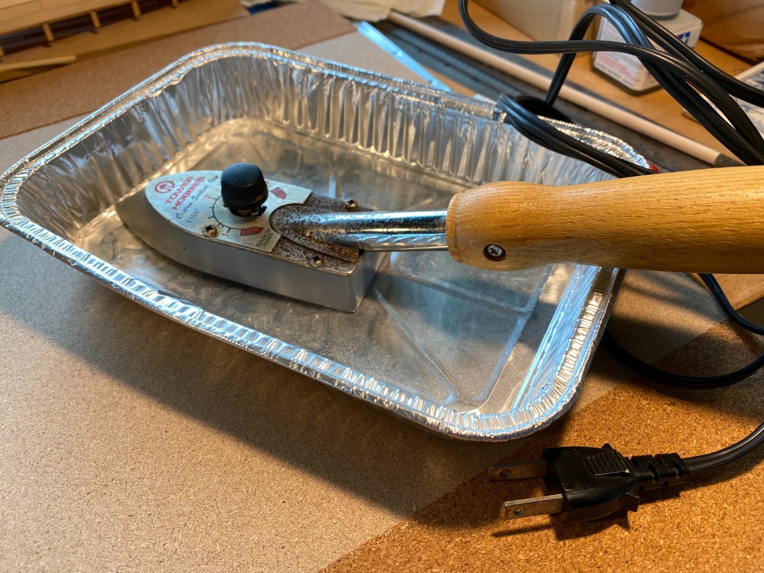
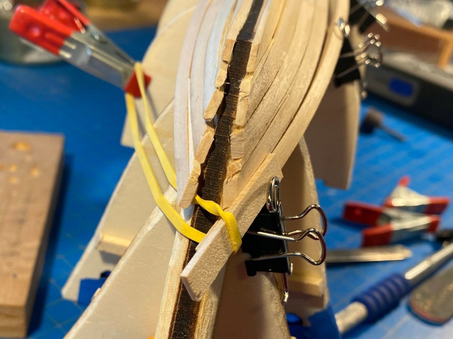
Slow progress since my last post . . . Since I intend to paint the entire hull, I think I’m going to try only one layer of planking instead of the two provided by the kit. A lot of filler and sanding, followed by a few layers of paint, have worked well for me in the past (most recently Joshua Slocum's Spray) and hopefully I can pull that off again. In the meantime, that first layer looks pretty ugly. I just recently read a couple of Chuck Passaro’s articles on his Syren website (particularly the second chapters of his Winchelsea and Medway Longboat instructions), and I’m hoping to learn a thing or two about planking from them. The instructions have you nail the planks to the bulkheads. I don’t think I have ever nailed anything to a ship model in the past (I don’t even have a hammer in my shipyard), and I’m not inclined to start doing that now. When it comes to bending planks, there are almost as many methods out there as there are bloggers on these boards. Several people on these boards have said that what makes a strip of wood bendable is heat, and that water is only the medium for transmitting heat. Rather than soaking, what has worked for me is to dip a finger in water, run your finger along the surface of the wood strip, then run an iron along the strip, slowly bending the strip to the desired shape. Multiple applications of water and heat may be needed. While I still need to clamp in place while the glue dries, I do find that the wood becomes as pliable as it would have had it been soaked for some period of time in hot water. The iron I use is one I bought decades ago, made for applying Monokote to R/C airplanes (gliders in my case). OcCre being a European company (Spanish), all the wood is supplied in metric sizes. I used 1/16” thick strips to plank my previous POB builds, and the strips supplied in the kit are 2 mm, which is about 20% thicker. That calculation has convinced me that these planks don’t just seem 20% harder to bend, but that they really are that much more difficult to work with! I am now thinking that I will go back to where I was before I started planking. I’ll glue the decks in place, otherwise follow the order of things as directed in the instructions, and then continue planking, working my way down to what I have done to date.


- 206 replies
-
- 2
-
-
- Endurance
- Shackleton
- (and 2 more)
-
We're certainly looking forward to our trip Mike. Scotland does look like it has jaw dropping scenery,, and for the most part bad weather is only weather you didn't properly dress for.
- 206 replies
-
- 1
-
-
- Endurance
- Shackleton
- (and 2 more)
-
Nice work on your Endurance. Within the next week or so I'll be posting my progress on hull planking . . . so far, only 5 planks on each side. And as you'll see, my approach is to not worry about uneven planks, cracks, holes and gaps for now, and let filler, sanding and painting hide all the flaws. The precision in your first layer could be stained and otherwise unfinished. Great work!
-
You mean it rains in Scotland? 😀 Actually we'll be well prepared. ☔ And will hopefully have done some history reading. Thanks for the head start Keith, and nice work on your Endurance.
- 206 replies
-
- 1
-

-
- Endurance
- Shackleton
- (and 2 more)
-
Thanks for the likes and kind words everyone. Keith, I used my Dremel tool last night to do some fairing, and I was pretty happy with the results. You're right, you do have to be careful. It's a bit like doing brain surgery with a chain saw (although I guess I really wouldn't know). 🤕 As an aside, we're vacationing in Scotland later this summer . . . the big cities and north of there. Looks like Cumbria is northwestern England, so a little south of where we'll be. Definitely looking forward to it.
- 206 replies
-
- 1
-
-
- Endurance
- Shackleton
- (and 2 more)
-
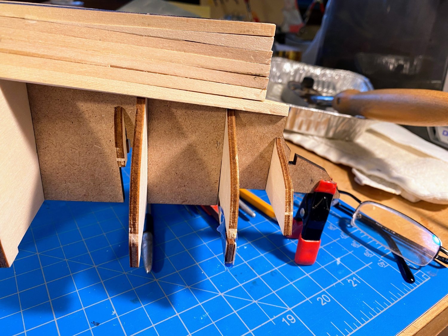
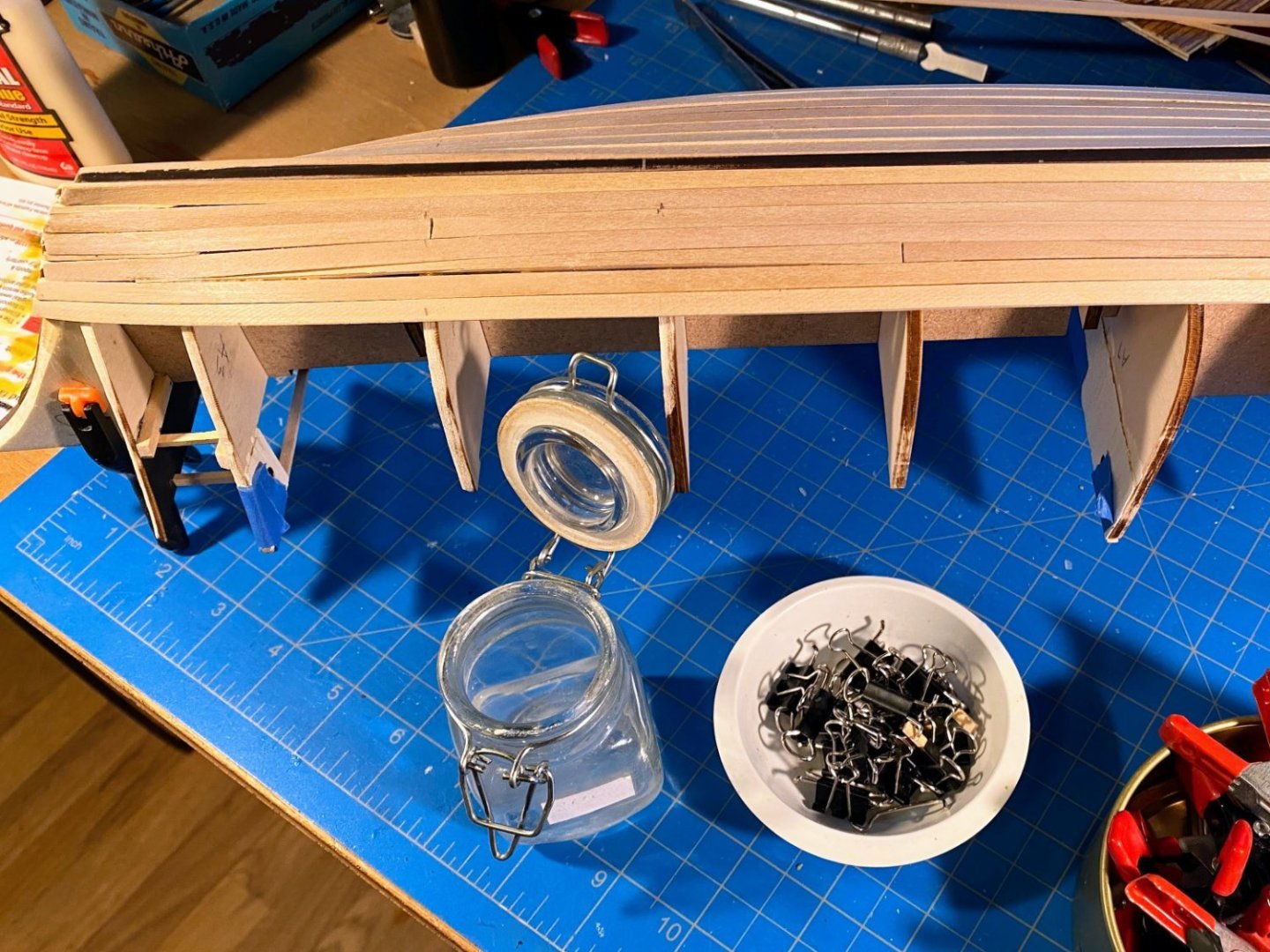
I have now finished planking and staining the upper deck and the aft deck. The aft edges of both decks need some clean up and perhaps even replacement of a plank or two, to cleanly cover the tops of the bulkhead planks, but I won’t attempt that until I am ready to glue the decks in place (more on this in a minute). I should have mentioned in my previous post that I did not incorporate treenails in my planks (obviously). My rationale is that with the narrower (⅛”) planks, that is a detail that is just too small to do effectively. Someone will undoubtedly prove me wrong (or already has). The instructions call for gluing the decks in place, as well as the bulwarks (and accompanying stanchions), aft cabin sidewalls, and various other things before planking the hull. My hull planking always seems to involve a lot of not-so-gentle man-handling of the hull, so I decided to plank most of the hull with little more than bulkheads in place. I don’t want to risk damaging any of the work I’ve already done. The first step of course is to glue in the supplied filler pieces (and perhaps some full on filler blocks) and fair them and the edges of the bulkheads. I’ll start at the keel and work my way up, at least for a while. Right now I’m thinking about how best to fair the planks into the stem and keel.

- 206 replies
-
- 8
-
-
-
- Endurance
- Shackleton
- (and 2 more)
-
Thanks Keith, that makes a lot of sense. I think I'll simply devise some sort of coal hole cover for holes that aren't really there. Yes, I haven't forgotten the WC and lamp locker walls. The anchor deck isn't glued in place and probably won't be for some time to come.
- 206 replies
-
- 1
-
-
- Endurance
- Shackleton
- (and 2 more)
-
A lifetime ago I built and flew R/C gliders. They didn't look much of anything like a full size plane, but they were a lot of fun to fly.
-
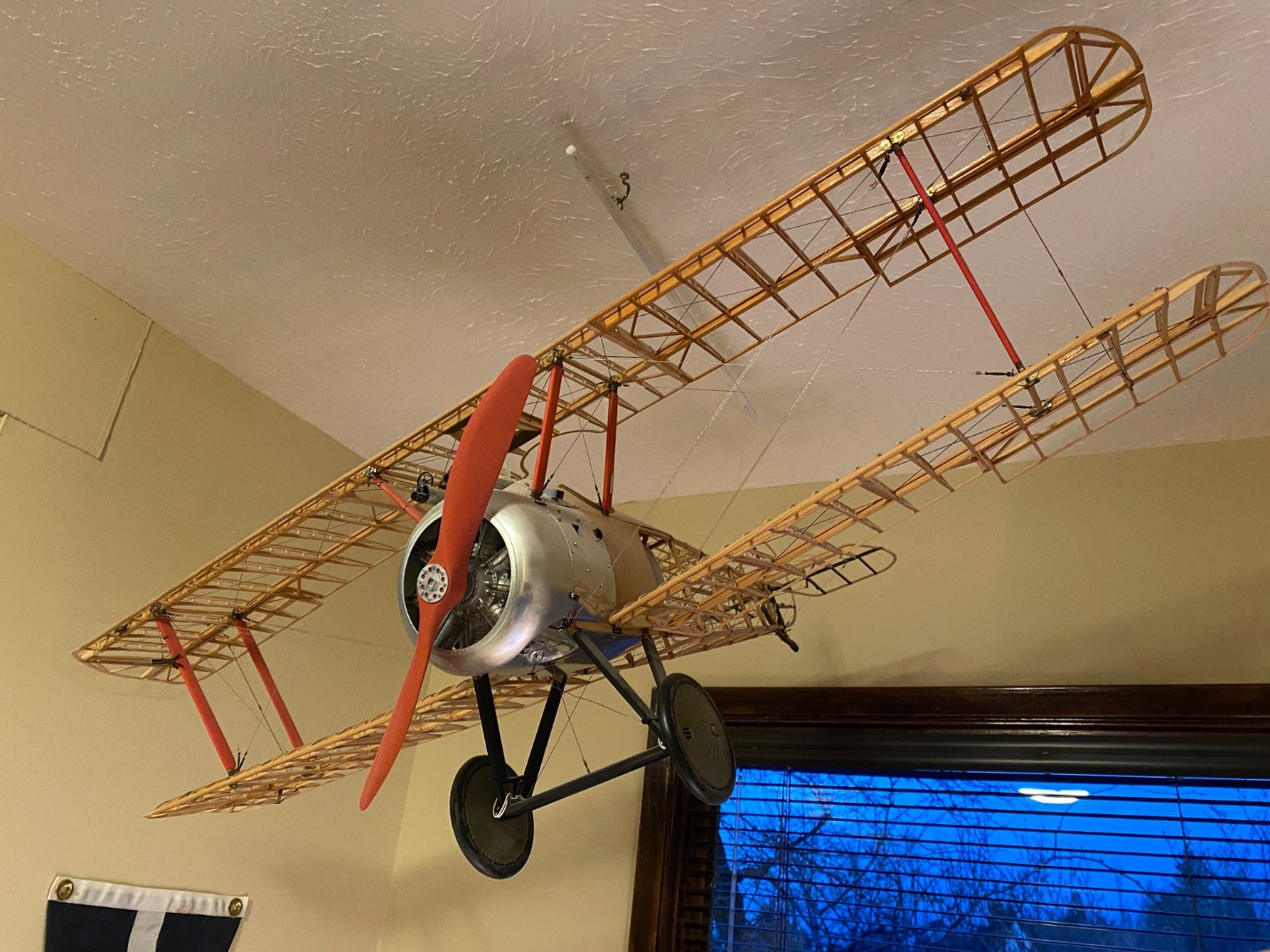
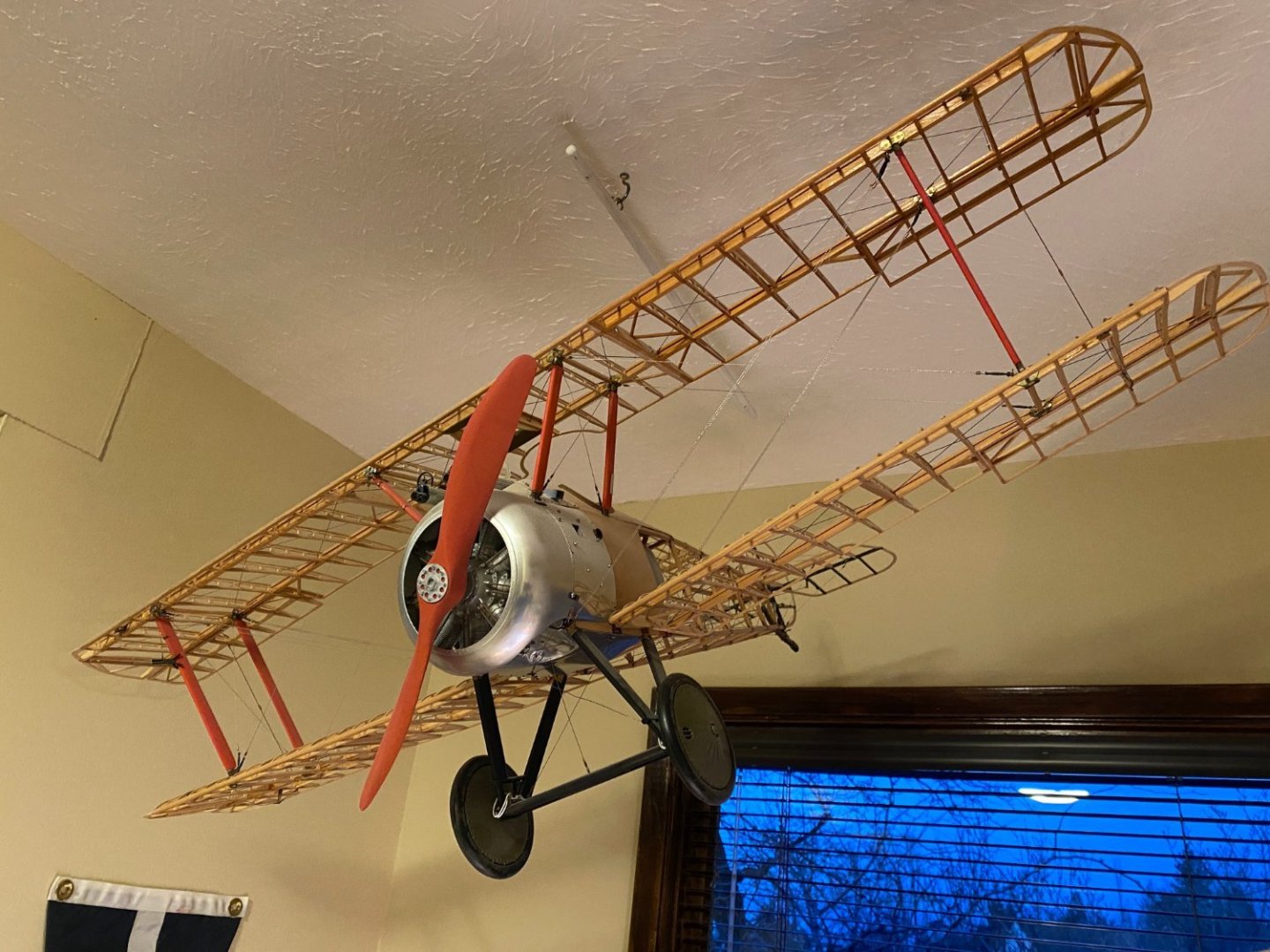
Bill, a 90" wing span on a 1 1/2 Strutter!! That's a gigantic (and interesting) plane. My Sopwith is about half that size. A friend of mine, about 35 years ago, called me one day shortly after his father died and asked me if I would like to finish the half completed model airplane his father was working on when he passed. I told him it may take a couple of years or more and that due to an impending move I'd have to ship it to him on completion. He told me the only commitment he wanted was that I would someday finish the job, and he did not want me to send it back to him. So it's been a privilege to have it hanging from my ceiling for quite a few years. When you get the time, your Strutter will be well worth finishing. Tom
-
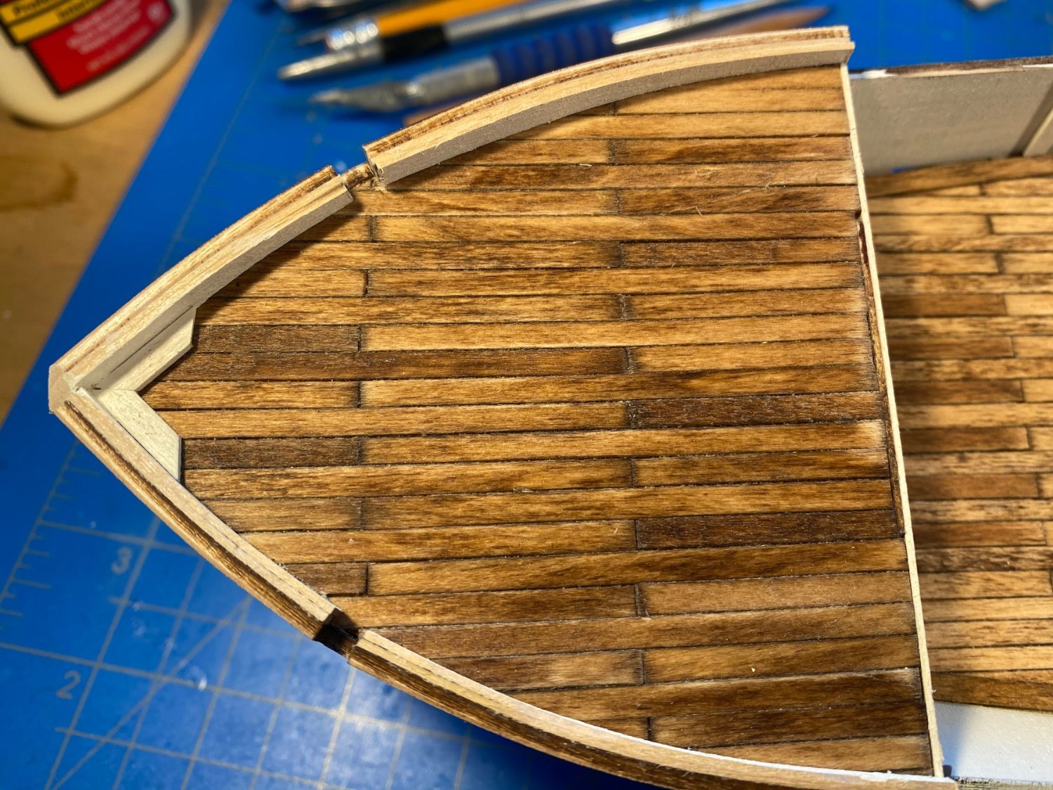
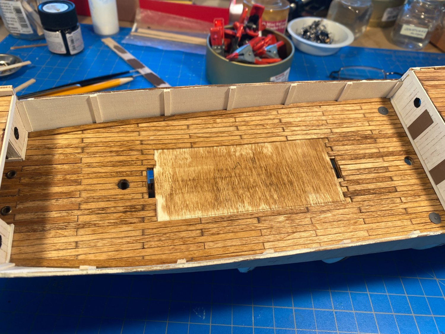
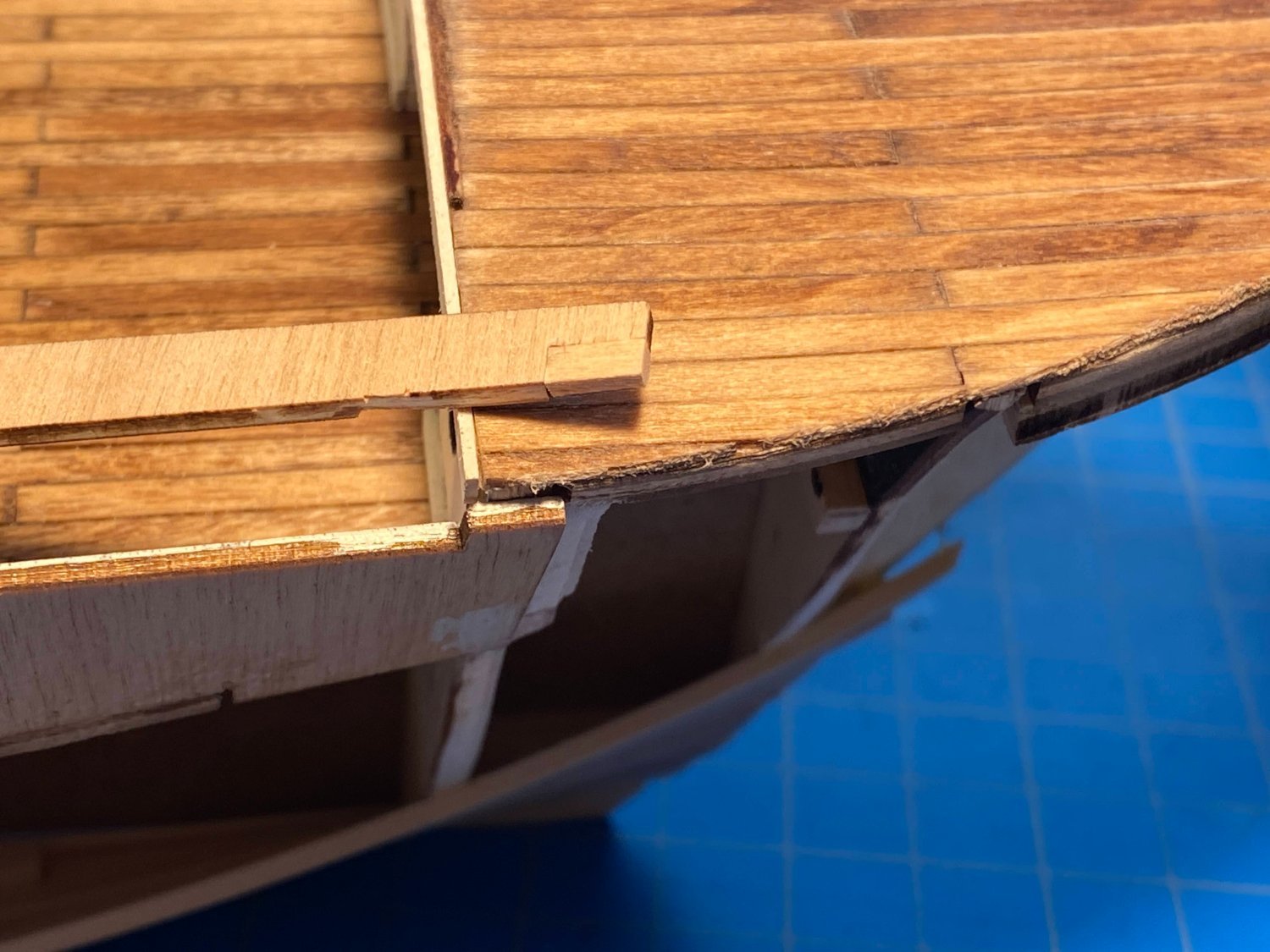
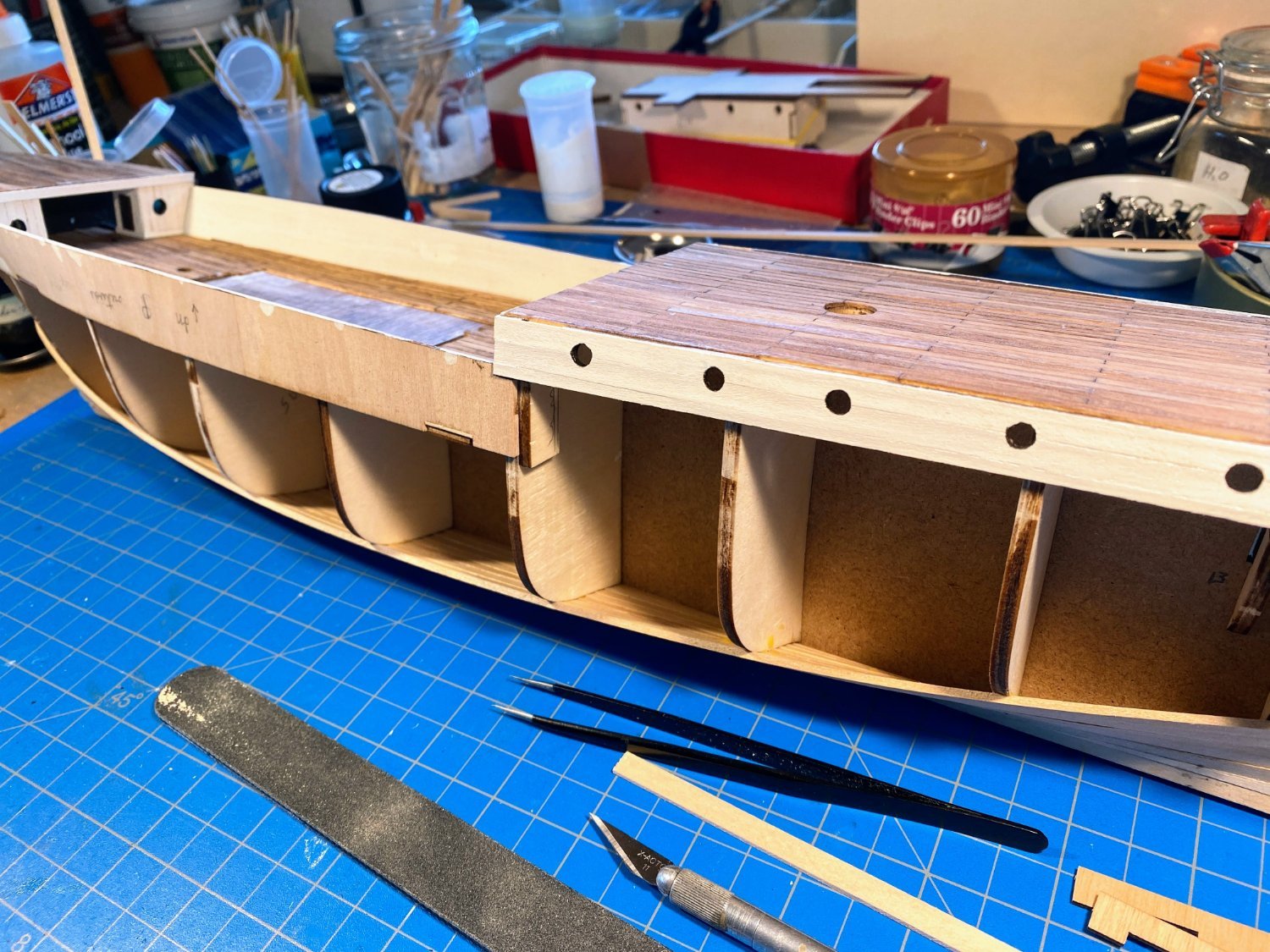
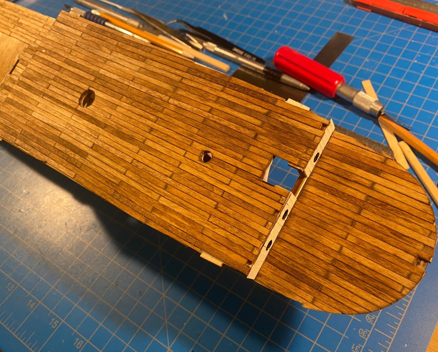
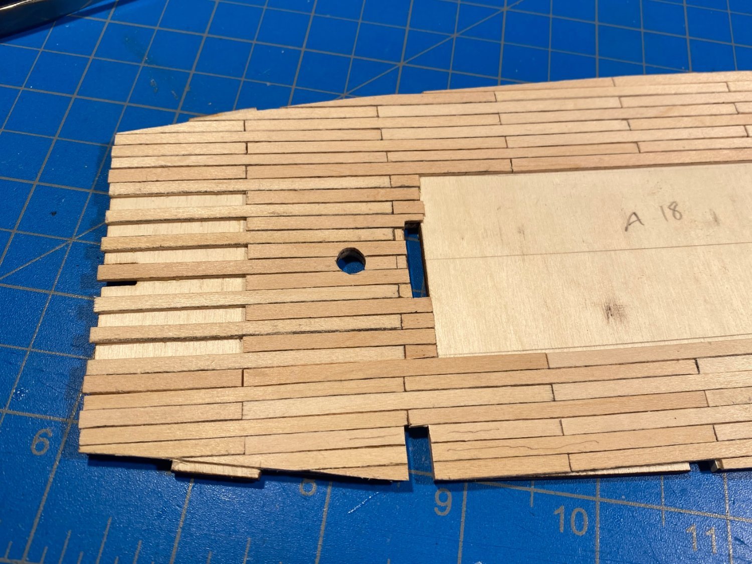
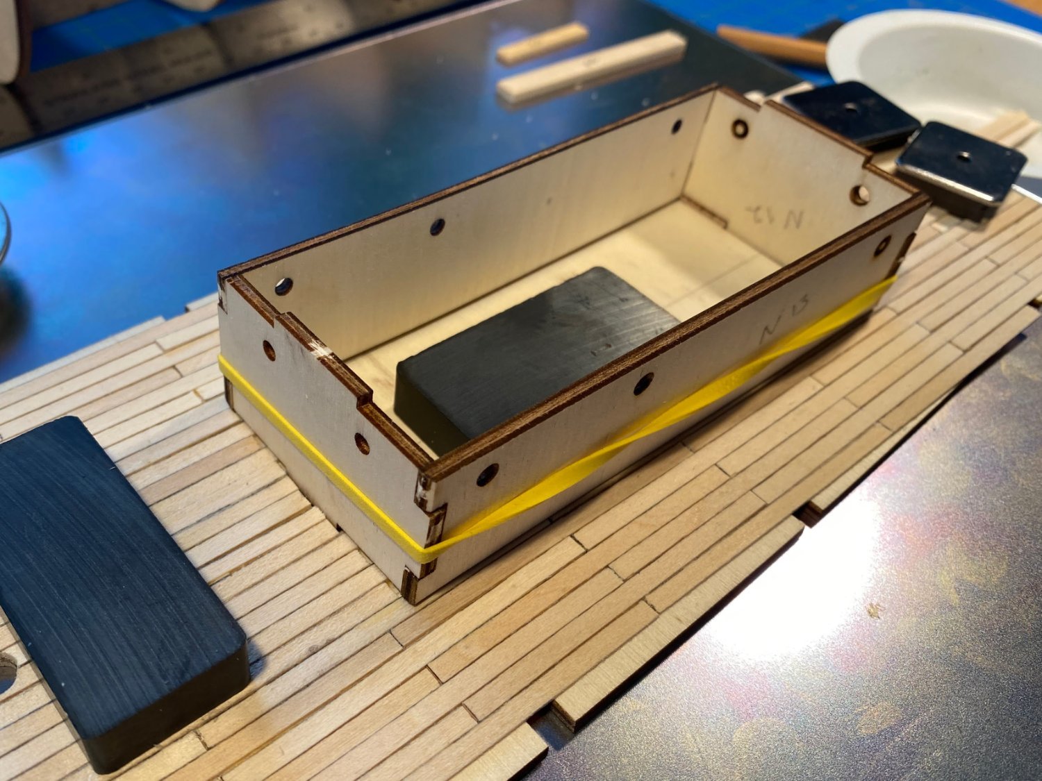
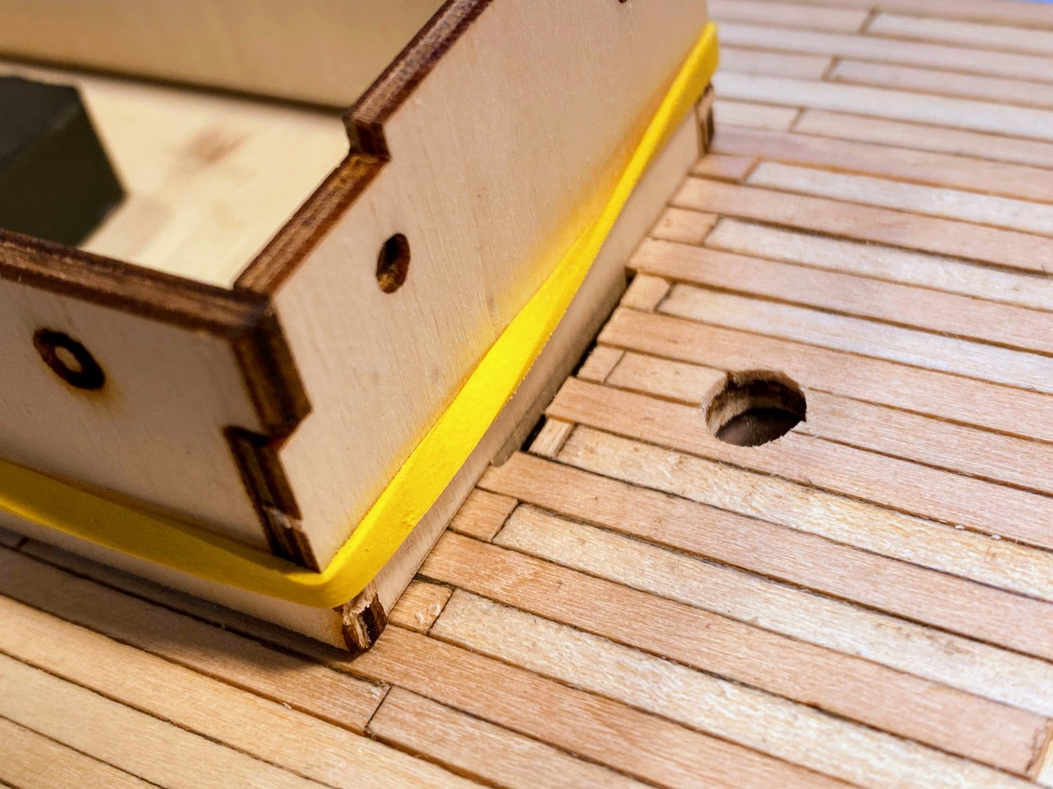
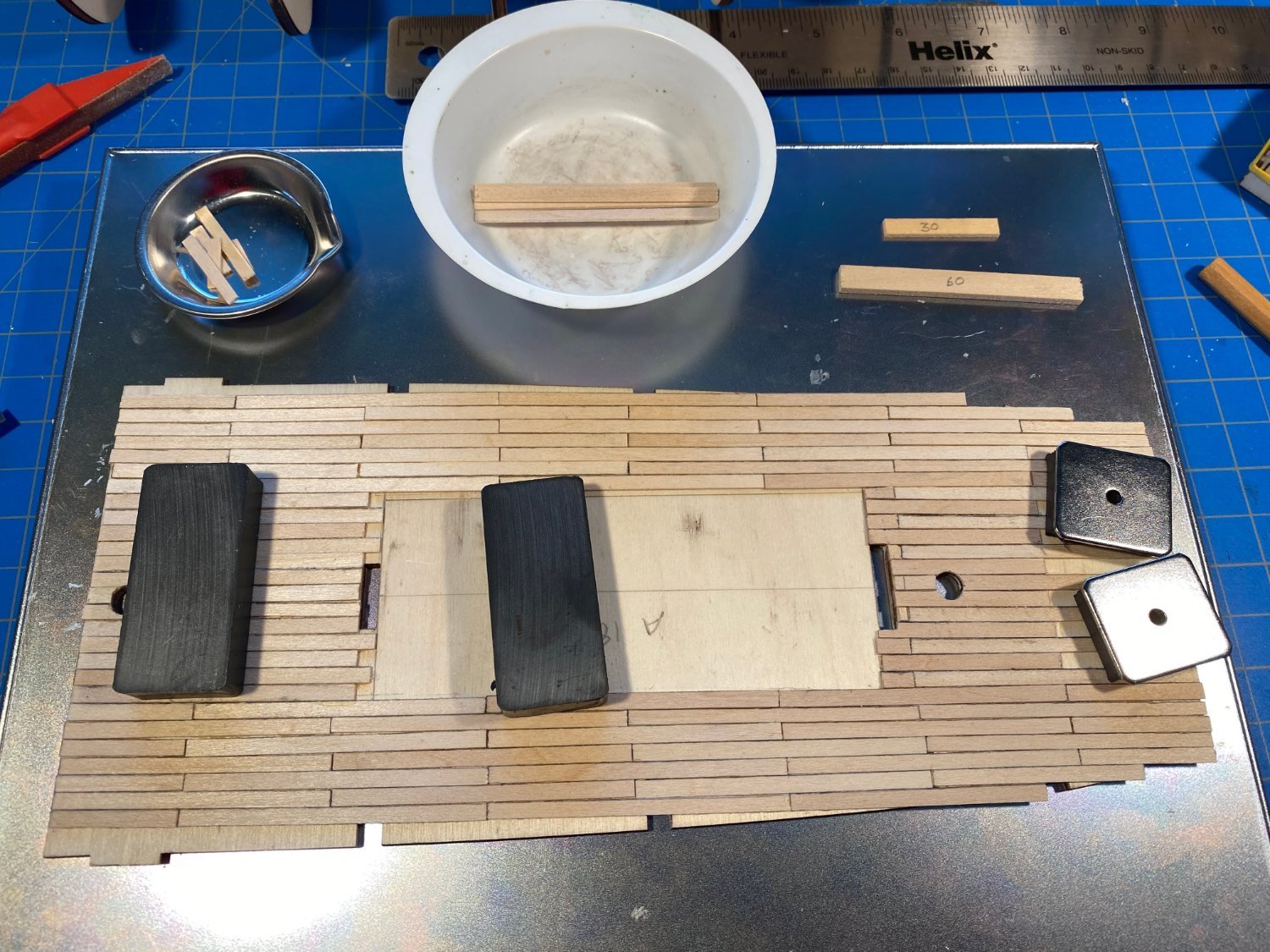
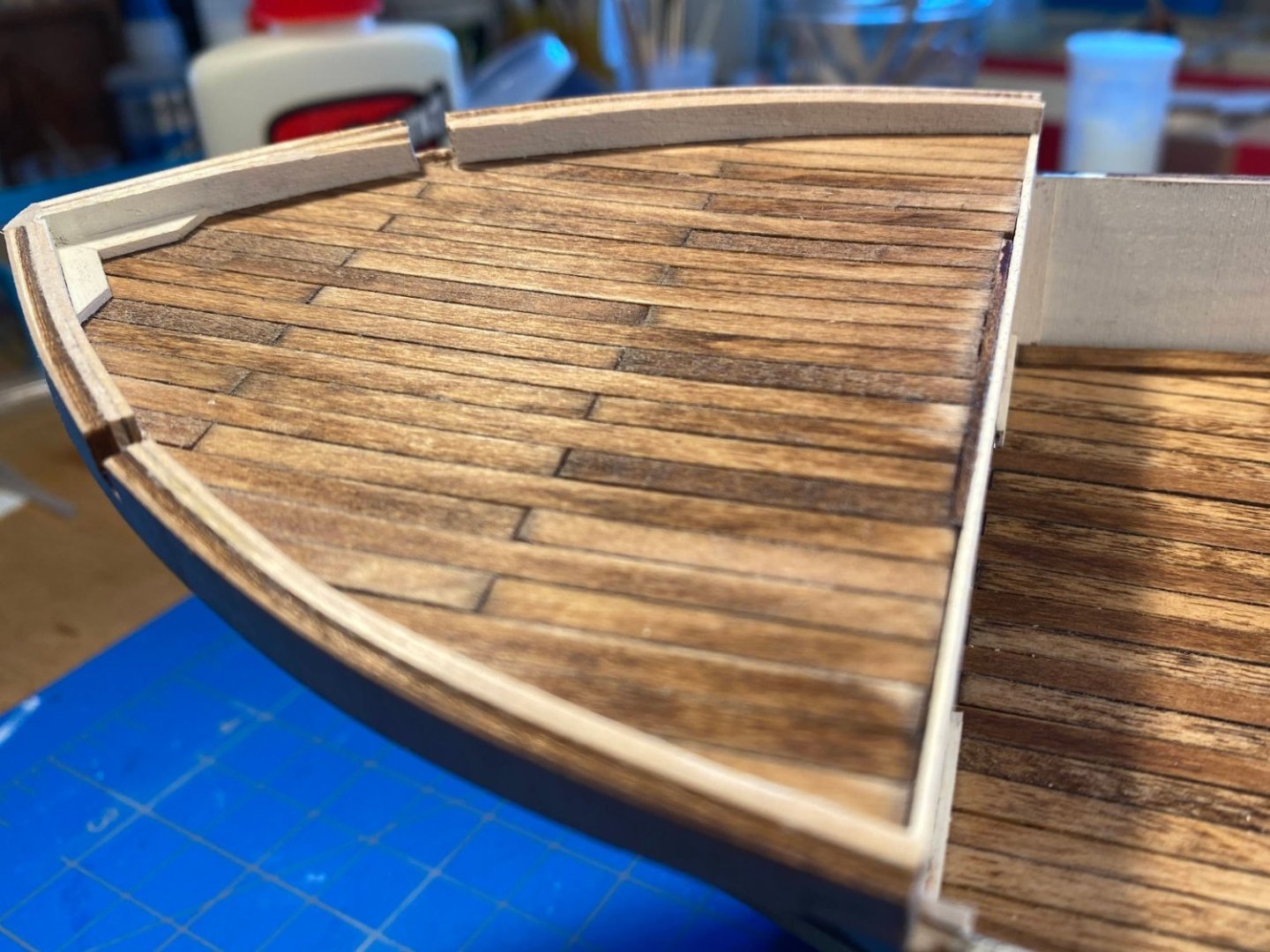
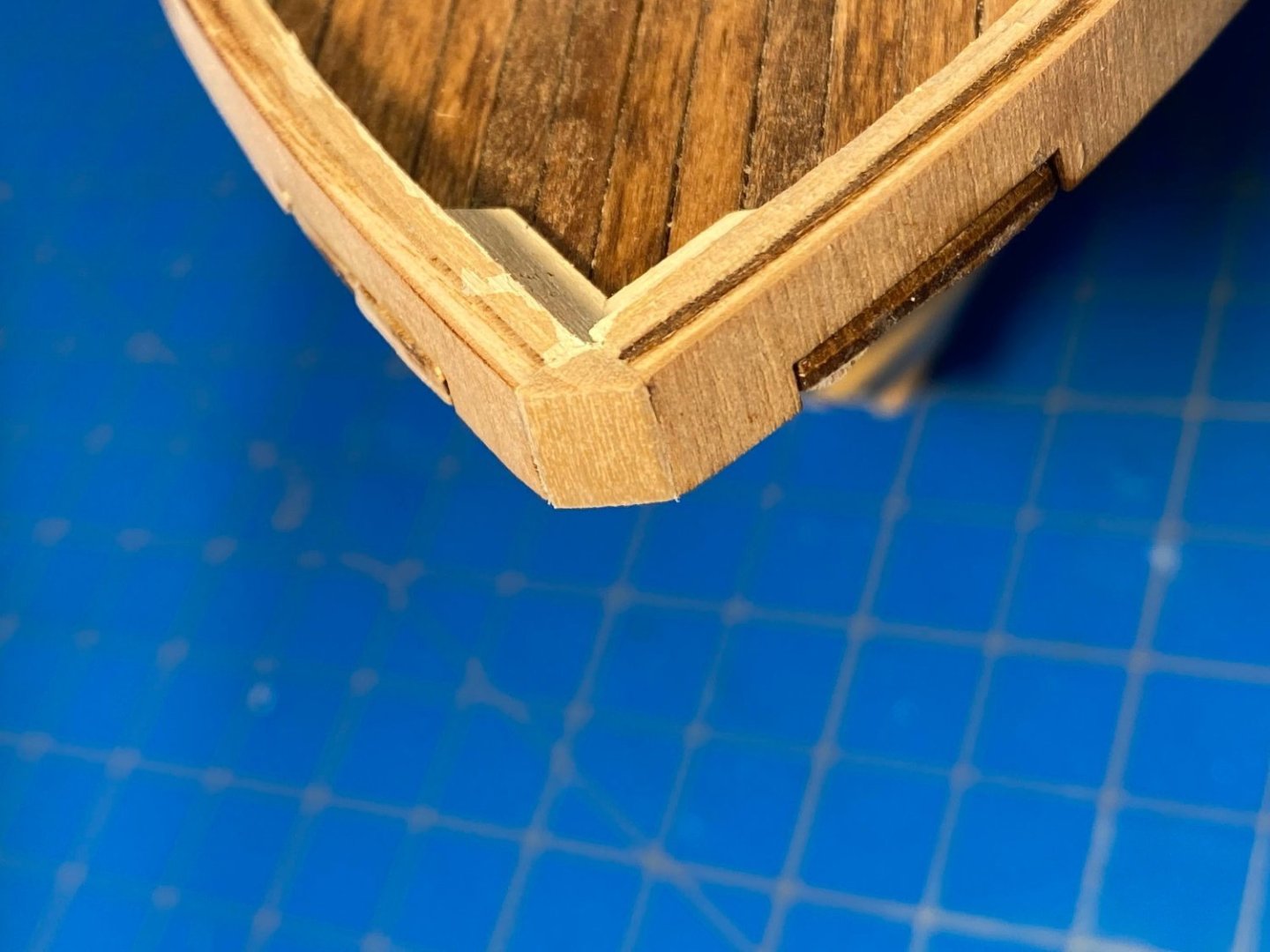
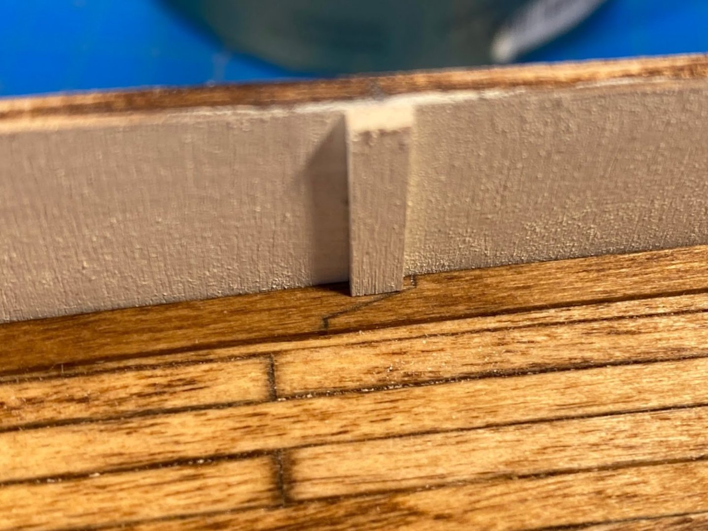
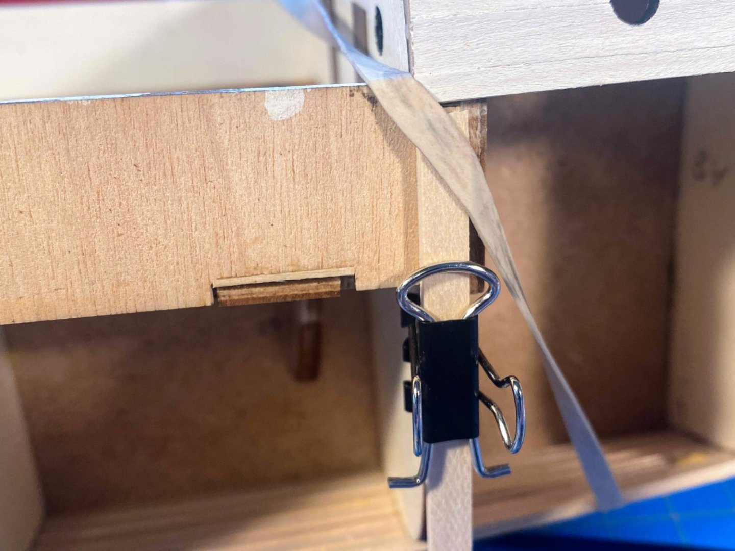
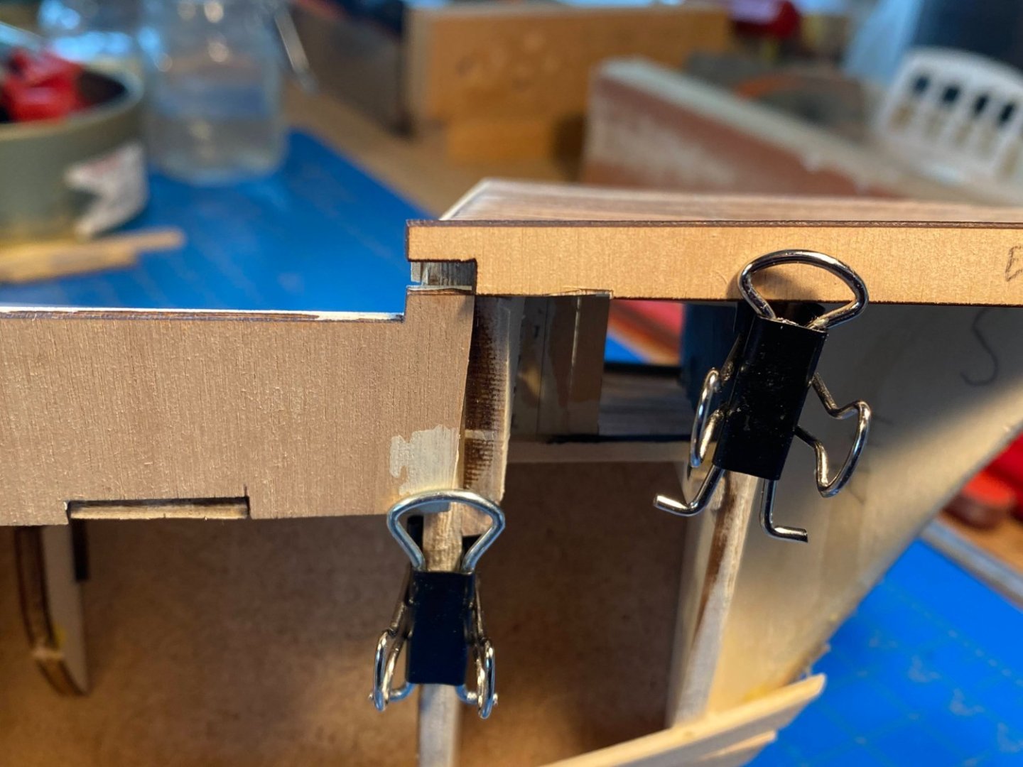
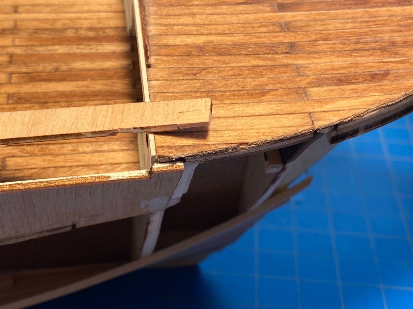
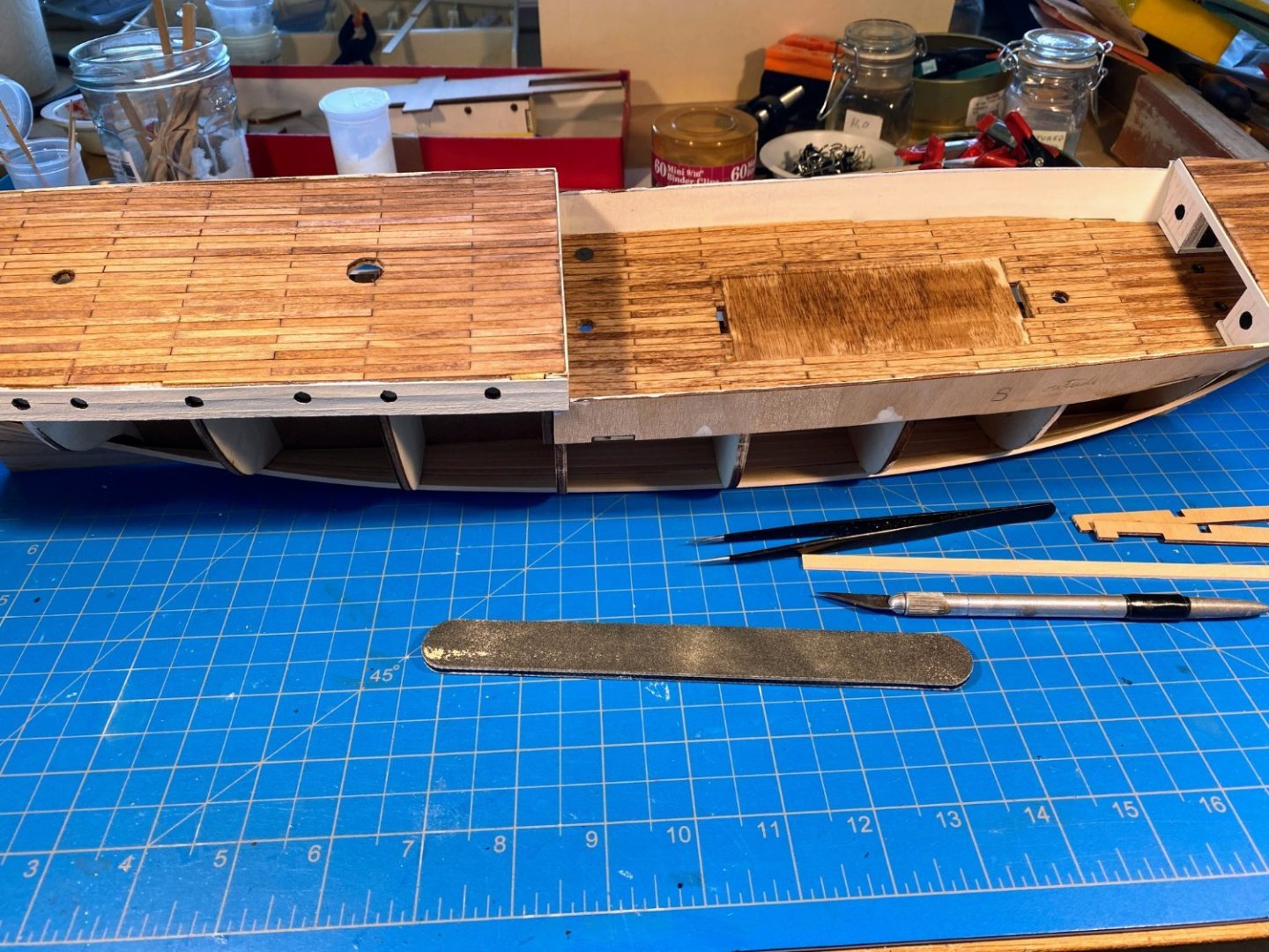
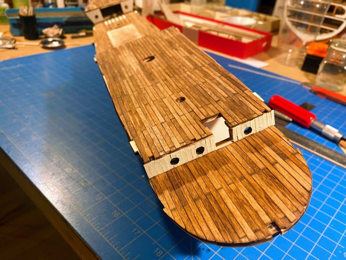
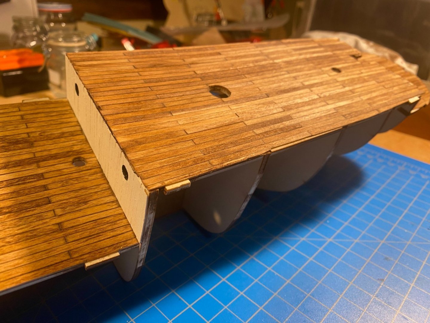
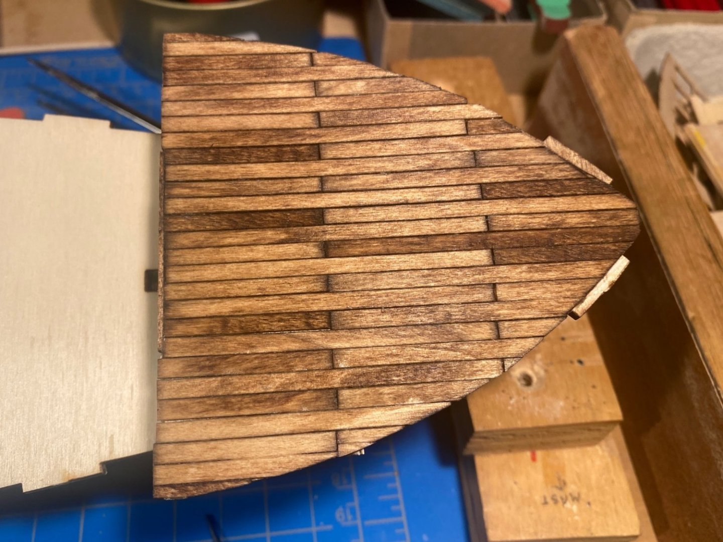
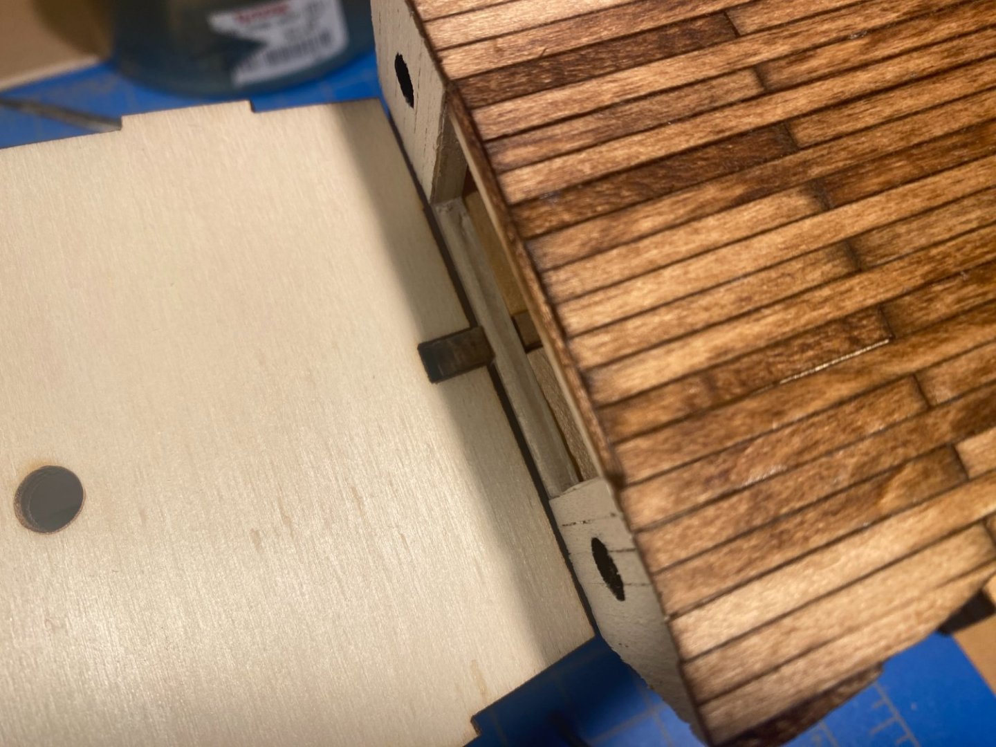
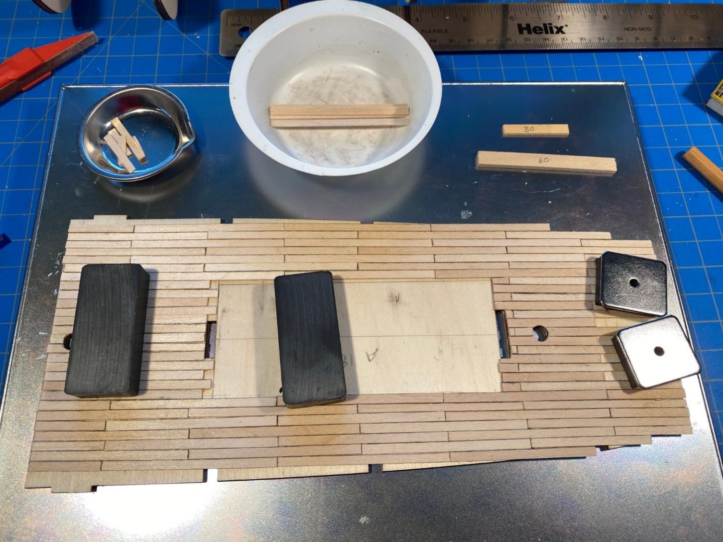
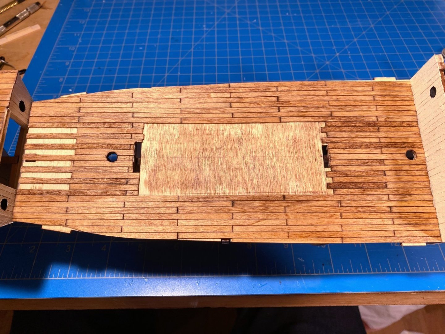
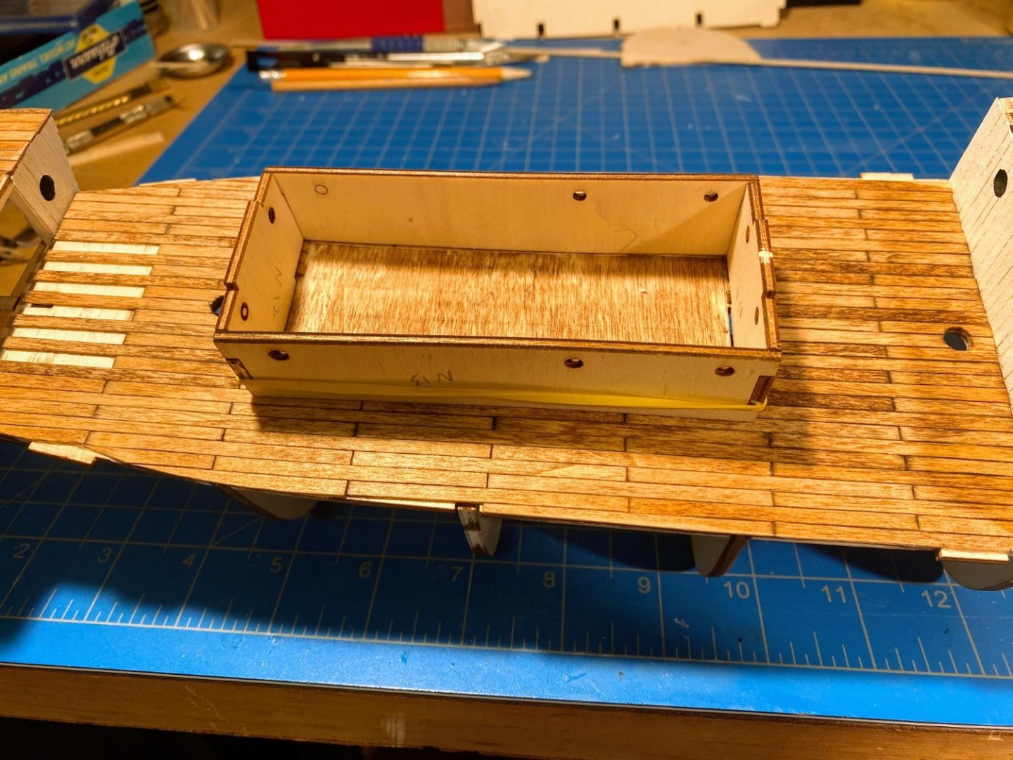
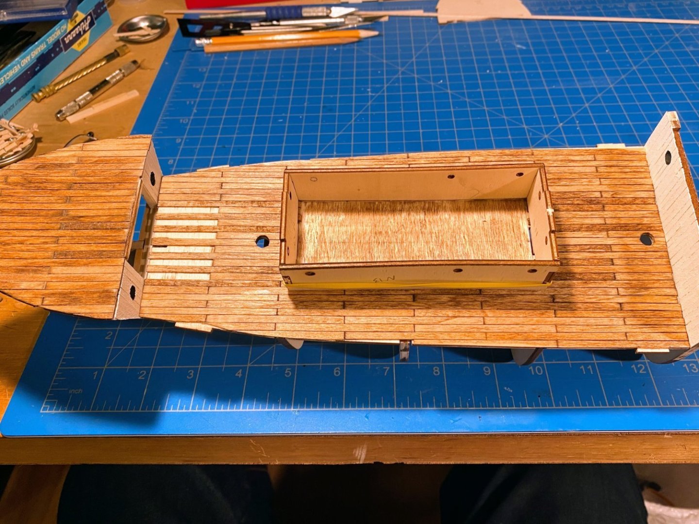
The foredeck and what I am calling the lower deck are now planked. Some observations: As mentioned previously, the supplied 0.6 x 5mm strips are, to my eye anyway, too wide. I therefore ordered a handful of 1/32 x 1/8 planks to use instead. Assuming my calculations are correct, 5mm translates to about 13¾” wide on the real deck, while 1/8” is a more reasonable 8¾“. I had several stains hanging around, and after a brushing few dabs of each on the backside of the lower deck, I chose one labeled Red Chestnut. I applied Verathane wood conditioner first, brushed it on the foredeck, wiped off the excess, and then let it dry for a few hours. Then I applied a coat of stain. I am not super pleased with the result. It’s darker than I expected, and blotchy. There are plank specific inconsistencies in the appearance, and that’s OK since it highlights the fact that this deck is actually planked with individual planks. But there is a blotchiness that covers multiple planks that I’m not really happy with. Hopefully these issues will become less noticeable with an anchor or two and other deck furniture on deck. I began planking at the aft edge of the subdeck, but then realized as I worked my way out from the center to the edges of the opening below that I should have extended the planks 0.6mm beyond the subdeck, to cover the tops of the planks I previously glued to the bulkhead. Hard to see, but in the photos you can see that I added a 0.6mm strip across the top of the opening to fill the gap. The ends of the deck planks and the face of this strip will be hidden by a strip which will eventually run the width of the ship across the top of the bulkhead. On to the lower deck. Every other plank will extend into the open area under the foredeck, and those planks will be glued in place only when the lower deck is glued in place. Both that deck and the foredeck are only dry fit in these photos. In ordering the narrower planks I made an arithmetic error in calculating how much I would need, and I forgot that the cabin has its own deck to be planked. In the hope that I would have enough wood strips without buying more (a futile hope I later realized), I left unplanked the area under the cabin. In retrospect that was probably not a great idea. Keeping all the planks straight and headed in the same direction, it’s a lot easier to work your way outward from a carefully located center plank. I ended up with some crookedness that fortunately is not very apparent. In the photo below, note the very stupid mistake I made (I think the medical term is “cranial flatulence”) -- while trimming the edge planks to conform to the subdeck, I very carefully cut out one of the slots that hold the top ends of the bulkheads. Those are supposed to be concealed under the planks. Fortunately removing and replacing the damaged planks was not as difficult as I feared. There are two slots in the deck intended to hold tabs on the pieces that make up the fore and aft ends of the cabin, and I cut my planks to leave these slots open. I later discovered that the slots are wider than the tabs that are supposed to fill them. And in the second picture below you can see that with the cabin slid forward to hide that slot, there is an unfortunate gap in planking at the aft slot. I’ve thought of a couple of possible remedies, but haven’t decided yet exactly what to do about that issue. As an aside I mentioned using the under side of this subdeck to test various stains. After the stains dried, I discovered that the subdeck had warped in kind of a wavy way, I guess due to the dabs of liquid. Some years ago I purchased a device designed to help in the assembly of things like cabins -- it’s a steel tray, with magnets to hold pieces in place. Generally it hasn’t proved to be as useful as I expected, but it proved to be very useful here. I turned it upside down and held the subdeck in place on flat bottom with some magnets that came with it, along with a couple of industrial strength magnets I had purchased for some long-forgotten purpose years ago. Planking the subdeck with it forced into an unwarped position reduced the warpage substantially, so that gluing it in place at the appropriate time will be easy. This time I applied the stain more carefully, trying to avoid any accumulation of liquid on the surface. I am much happier with the result, but it's still not quite what I would like it to be. The color isn’t consistent in the photos below, but I think the middle one is probably the most accurate. It's not as red as any of these photos. Finally, there are two holes near the outer edges of this subdeck in line with the hole for the main mast. I planked right over them for now. The instructions show what look like stacks or vents that go in these holes (maybe cookstove stacks?). Looking at the plans shown in my last post, I can’t see that they show up in the side view, but the holes are definitely there in the deck views. Do any of you who have worked on this model or researched Endurance know what they are?


- 206 replies
-
- 5
-
-
- Endurance
- Shackleton
- (and 2 more)