HOLIDAY DONATION DRIVE - SUPPORT MSW - DO YOUR PART TO KEEP THIS GREAT FORUM GOING! (89 donations so far out of 49,000 members - C'mon guys!)
×


Tomculb
-
Posts
345 -
Joined
-
Last visited
Content Type
Profiles
Forums
Gallery
Events
Everything posted by Tomculb
-
 Thanks Craig. Like you I have assembled a pretty good collection of photos, mostly bookmarked, some downloaded, and some in a Frank Hurley book I bought. But I have never taken the time to organize or catalog them, so it takes me forever to find what I'm looking for (if I find it at all). I really appreciate what you have shared.
- 206 replies
-
- 1
-

-
- Endurance
- Shackleton
- (and 2 more)
-
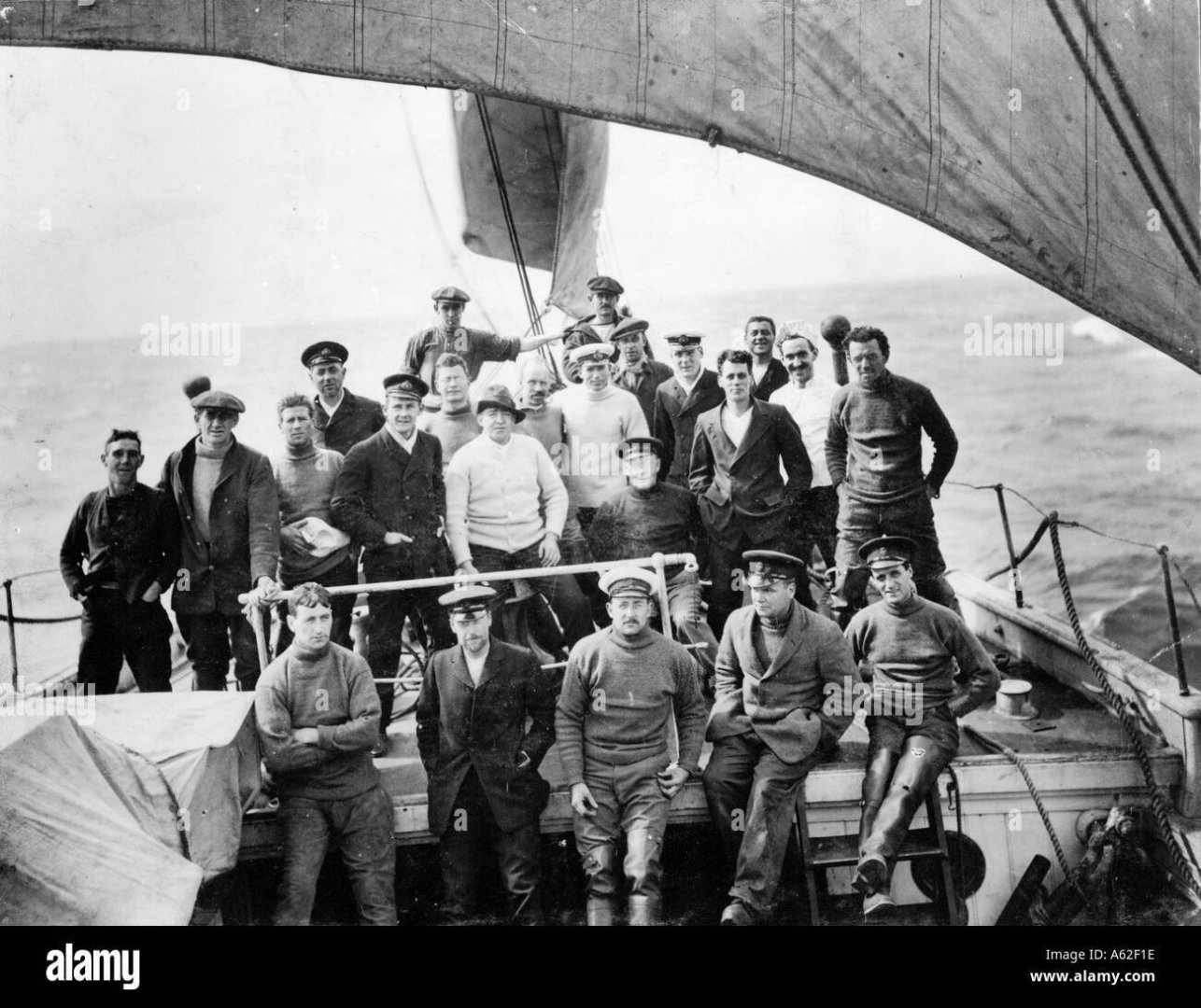
Craig, as I look at the second photo you posted, it looks to me like the guys may be attached to the boat davits. Which makes no sense since the plans I have found online and OcCre position the davits aft of the funnel. Maybe sometime late in the journey the davits were moved forward to be in line with the funnel? All of this assumes I have my shipboard geography right. As I look at that photo, it is facing aft from just forward of the main mast, and the sort-of-round things in the middle are, moving aft in the picture, the mainmast forward gaff, the main mast, and the funnel. Further aft you can’t see the mizzen mast, but you can see its ratlines. This assumes that the intake funnels have been rotated to face aft, unlike the first photo where they face forward and seaward. Any thoughts?
-
What bent pipe?? 😀 Thank you Josh for the inspiration and the picture.

- 206 replies
-
- 4
-
-
- Endurance
- Shackleton
- (and 2 more)
-
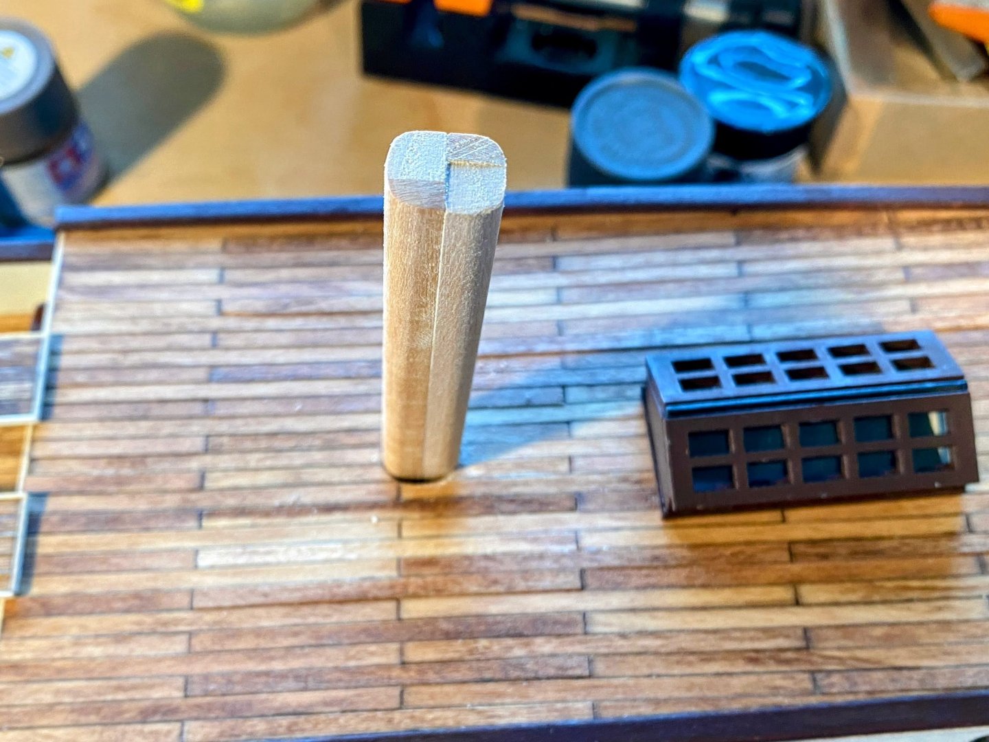
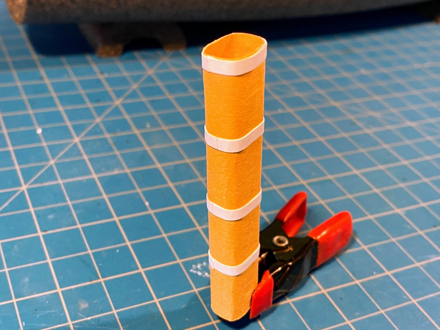
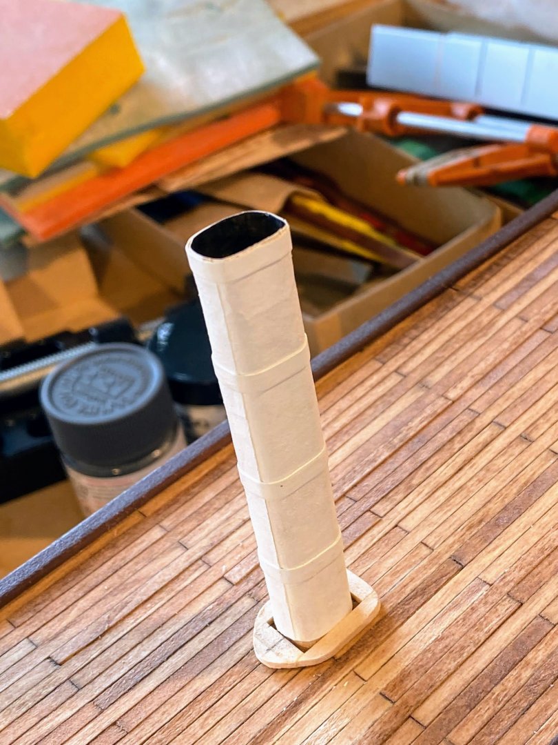
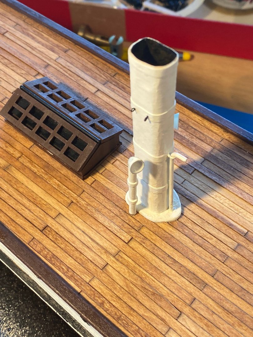
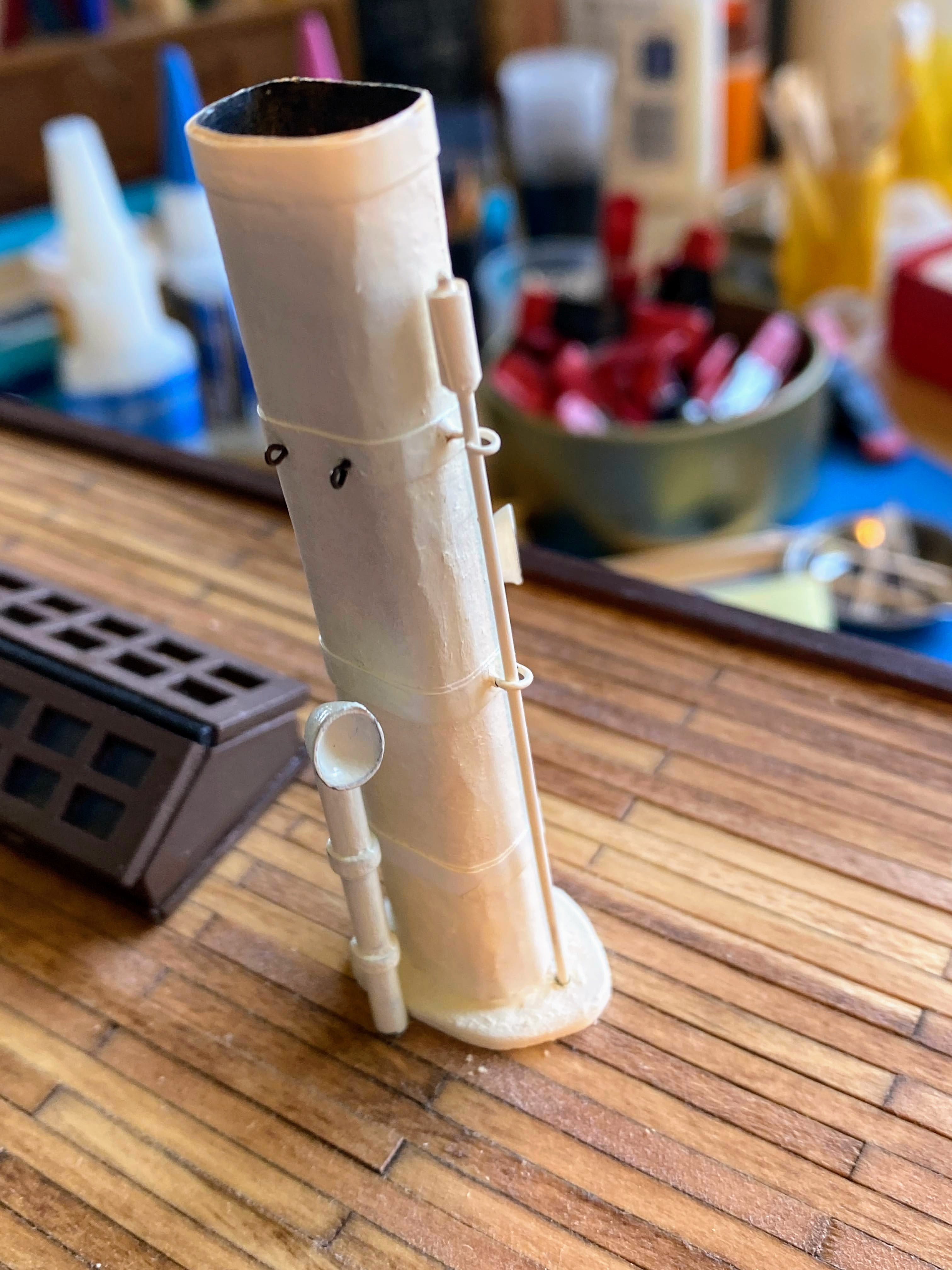
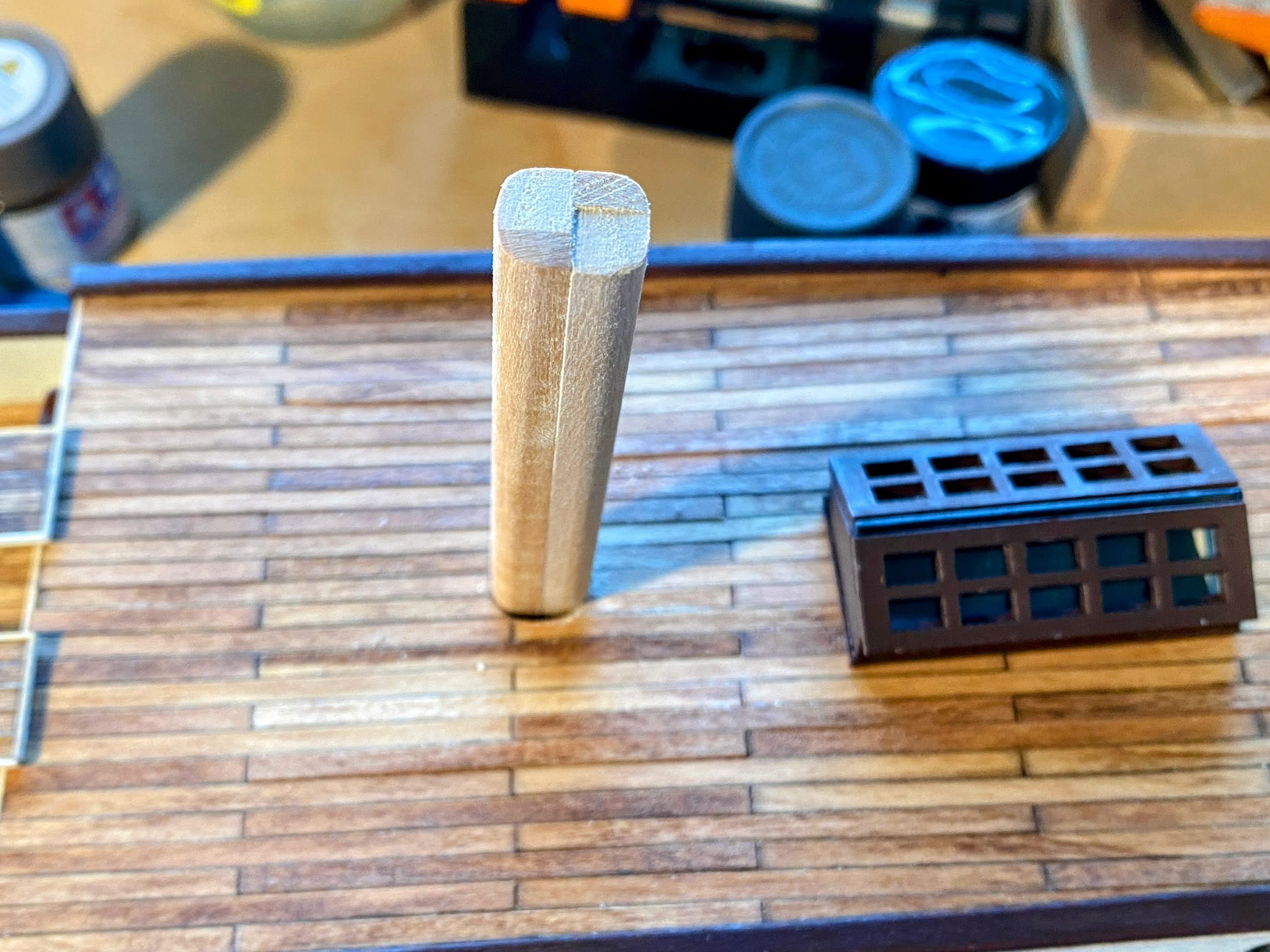
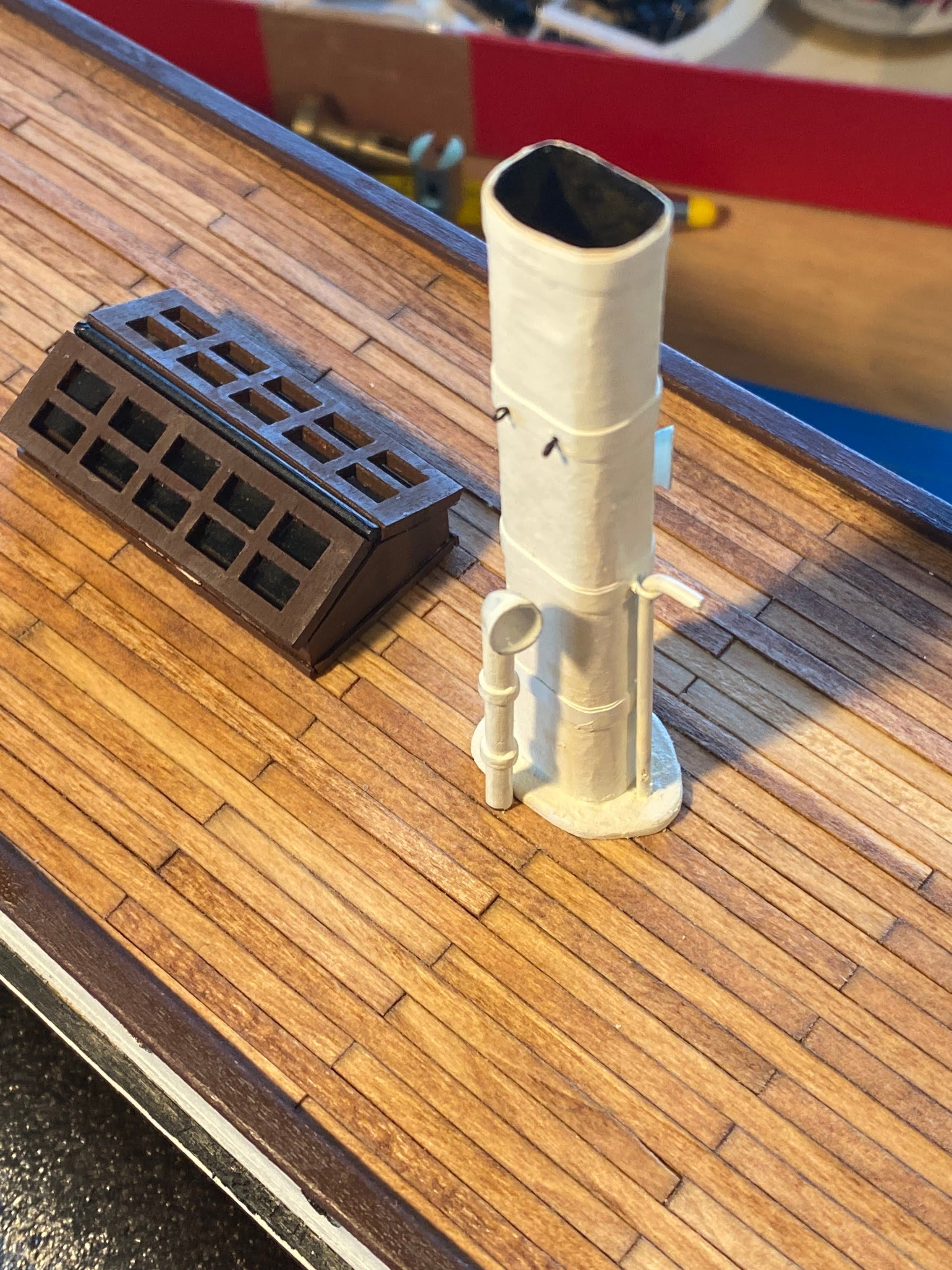
The funnel . . . The kit includes a 12mm dowel to use for the funnel, but I decided to try to make something that better represents the real thing. Rather than round, Endurance’s funnel is more like a rectangle with rounded corners. I took two 1/4” square strips, and two 1/8” x 1/4” strips, laminated them together to form a 3/8” by 1/2” column of the height of the funnel, and sanded the edges round. I suppose if I had metric dimensioned wood strips, the column would have fit better in the laser cut hole in the deck. I had to use my Dremel tool to enlarge the hole a little. To simulate a hollow funnel, I cut about 1/2” off one end of this wood column, and then wrapped the column in paper. It took me quite a while to find paper that was stiff enough for the top but didn’t crease when bent around the corners. What worked pretty well (even though it was orange) was a divider page in a very old spiral bound notebook. Frank Hurley photos show flat bands around the funnel, which OcCre simulates with brass wire. I used Tamiya’s masking tape for curves instead, each strip being wrapped twice around the funnel. I painted the funnel white; more than one coat was required to hide the orange. I then painted the hollow inside at the top black. At least with my aging eyes, it's hard to see that only the top 1/2” is hollow. Obviously the kit’s laser cut round base wasn’t going to work. I made a base gluing together several short 1/8“ x 1/16” strips, then sanding to get the desired shape. OcCre shows a bent pipe on the forward side of the funnel . . . I’m not sure what it is, but I decided to include it anyway. I used spackling paste to fill in the inside corners of the base, the same stuff I used in great quantities as filler when finishing the hull. The small intake funnels in the pictures below are supplied by the kit. OcCre shows them facing aft, but they face forward and out in the Hurley photos I looked at. Finally, those photos show cables leading from the funnel down to the deck. I attached eyebolts on the funnel for that. I won’t rig them until I have installed the dog kennels, when I’ll have a better idea where to attach the other ends of the cables. I also finally got around to gluing in place the previously assembled large skylight.
- 206 replies
-
- 2
-
-
- Endurance
- Shackleton
- (and 2 more)
-
I've long thought of "work" as a nasty four-letter word. Not that I wasn't fortunate enough to enjoy what I did, but I always enjoyed (and now enjoy without interruption) the alternatives better.
-
Josh, I know absolutely nothing about 3D printing, but I can see that such a printer could be invaluable when it comes to making custom ship model fittings. Google searching I see that a printer can cost anywhere from a couple hundred dollars to a few thousand. Any advice you could give to me and your other followers? Perhaps point us in the direction of a useful and informative site on the web for 3D printing 101? Thanks. And Travis (@Cenizas), I echo Josh's encouragement that you start a build log for your Endurance; I see that you started one for your Polaris build. You private messaged me (and others I assume) with good questions, but I suspect you would have gotten better answers if you asked your questions publicly. The wonderful thing about these MSW boards is how willing people are to help. And no matter how long some of us may have been building, I think most of us feel that we're still just beginners, with a whole lot more to learn.
-
Thanks Josh and Mike. Josh, I too pondered over the photo you posted and decided that the port ladder was probably a portable one they moved around from place to place. That would explain the longer than necessary rails. Of course that's purely speculation on my part.
- 206 replies
-
- 1
-
-
- Endurance
- Shackleton
- (and 2 more)
-
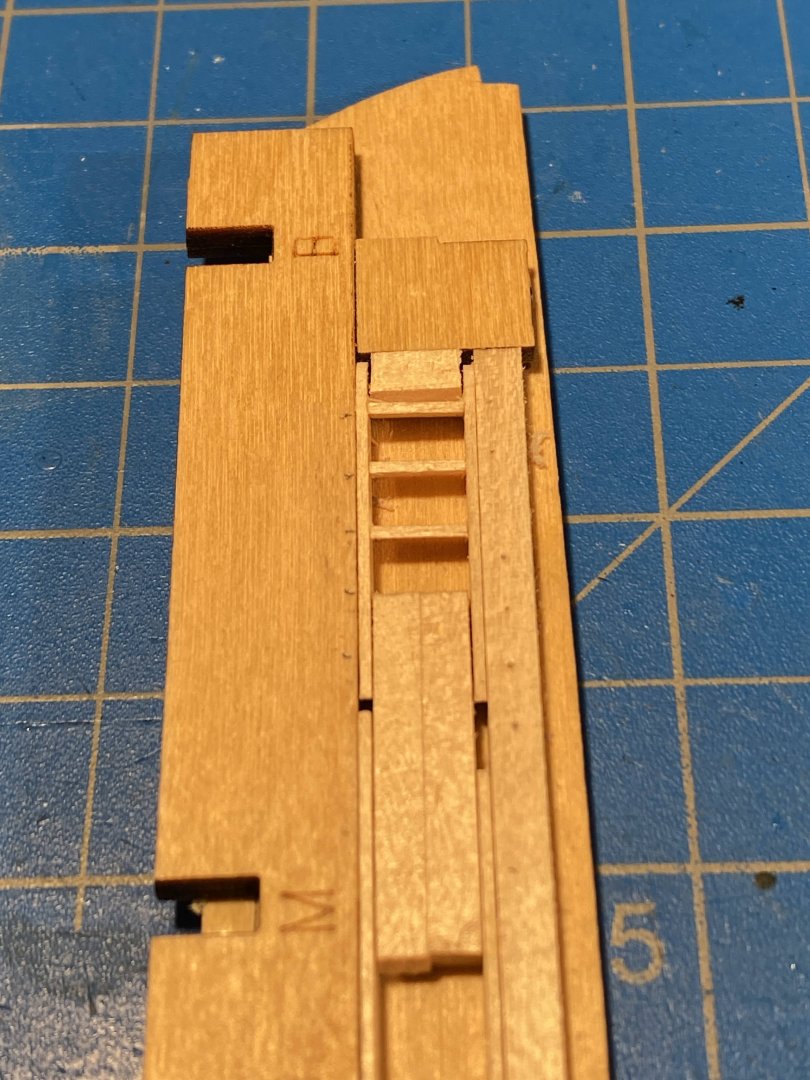
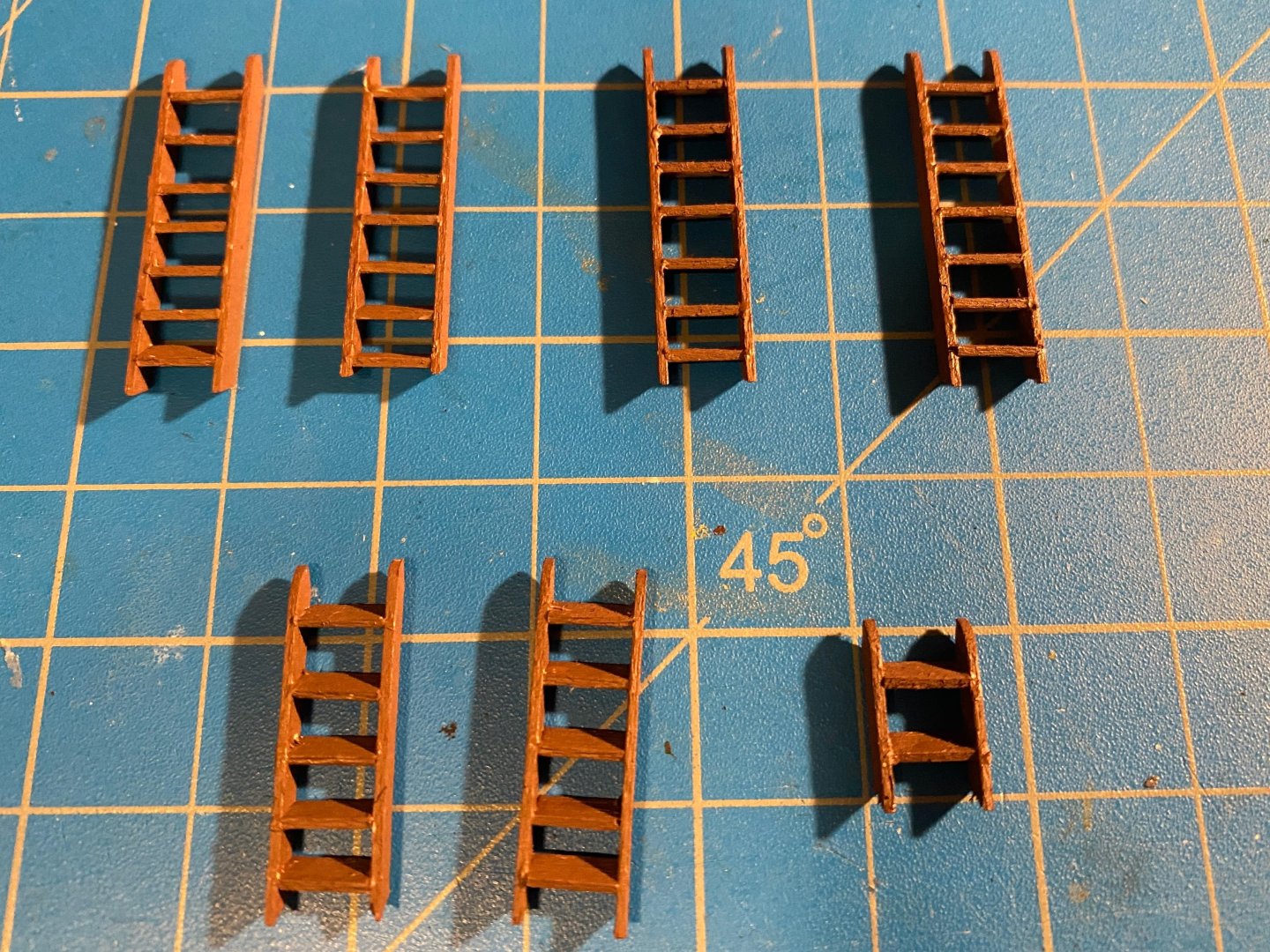
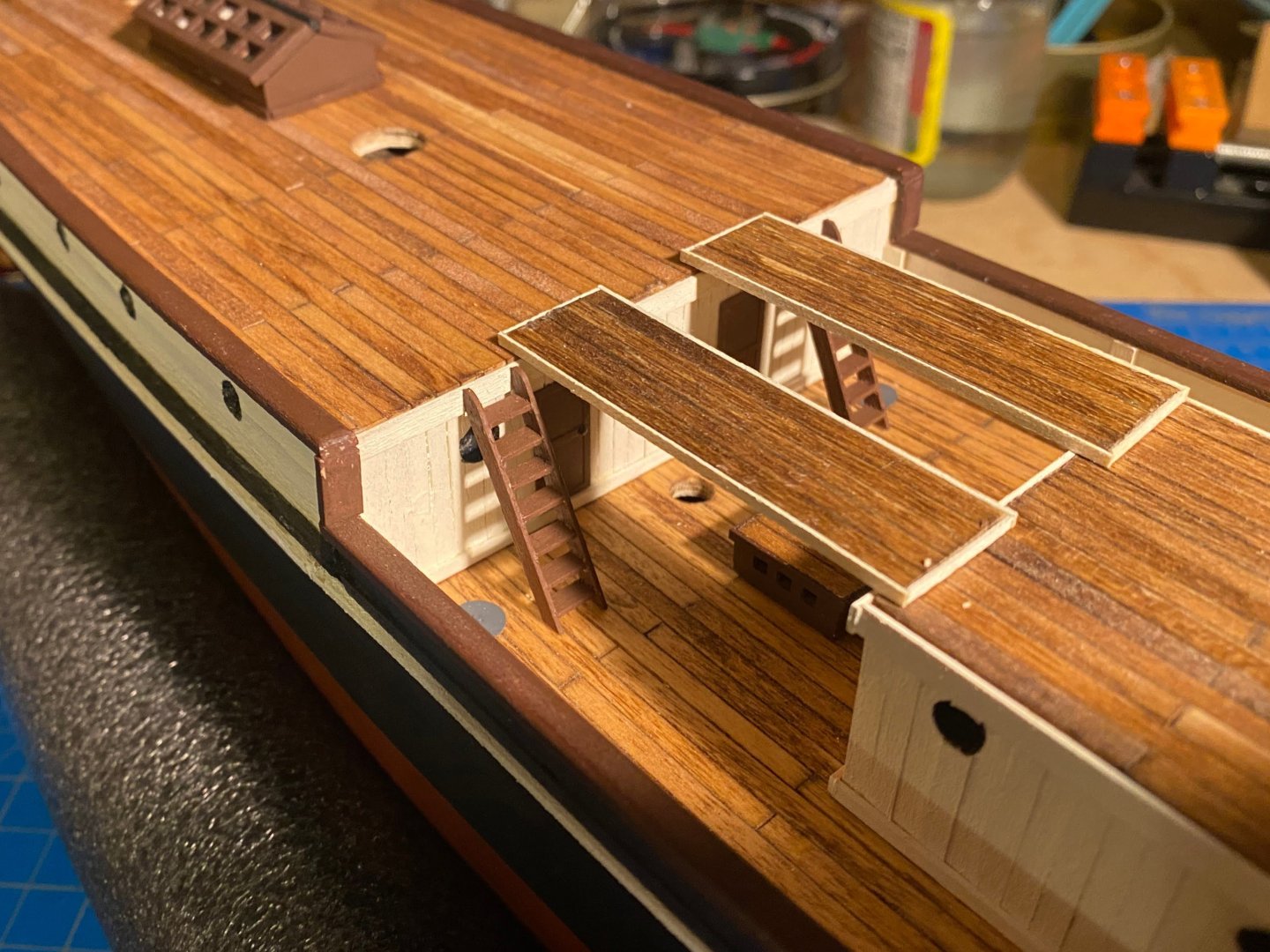
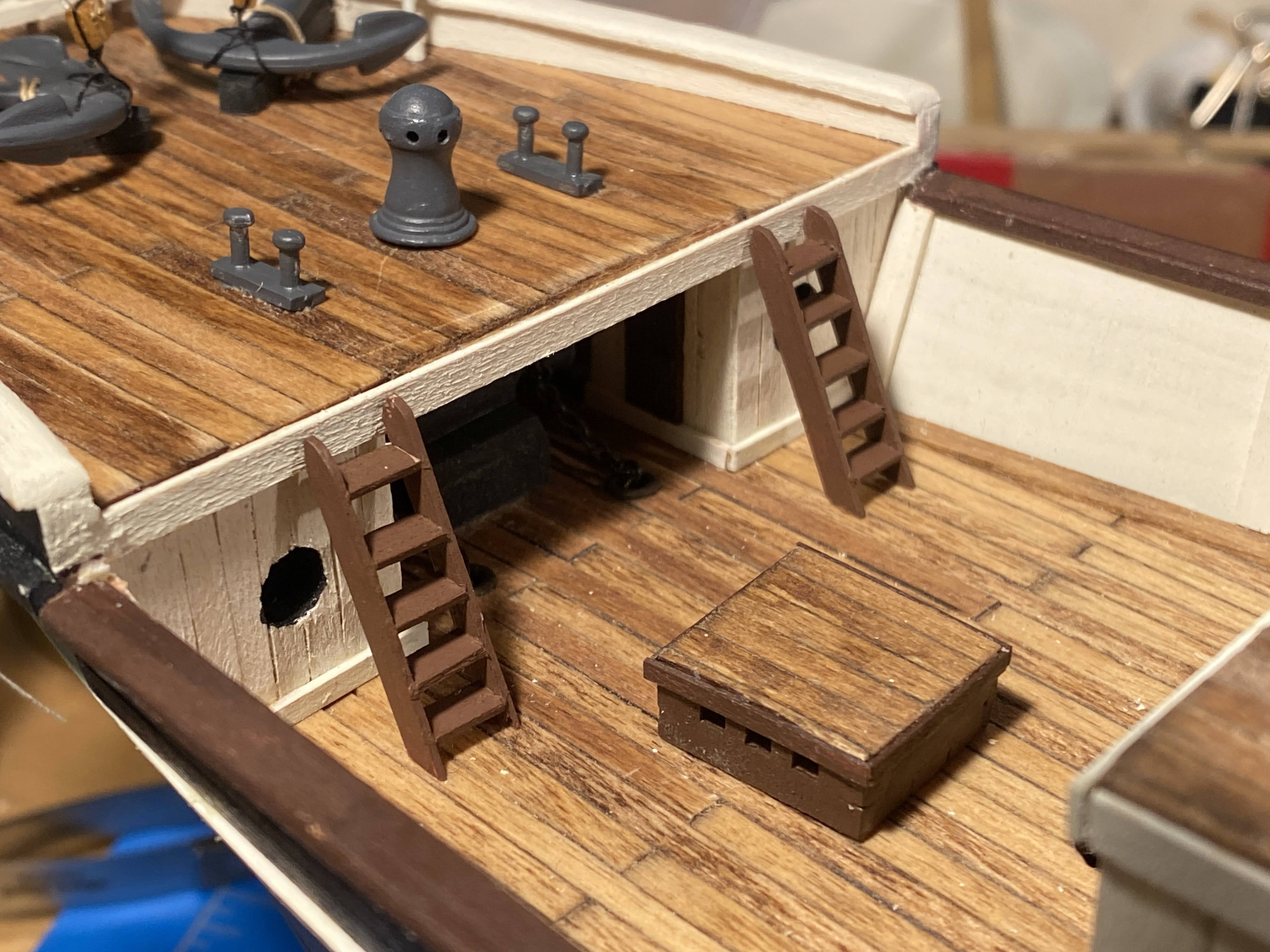
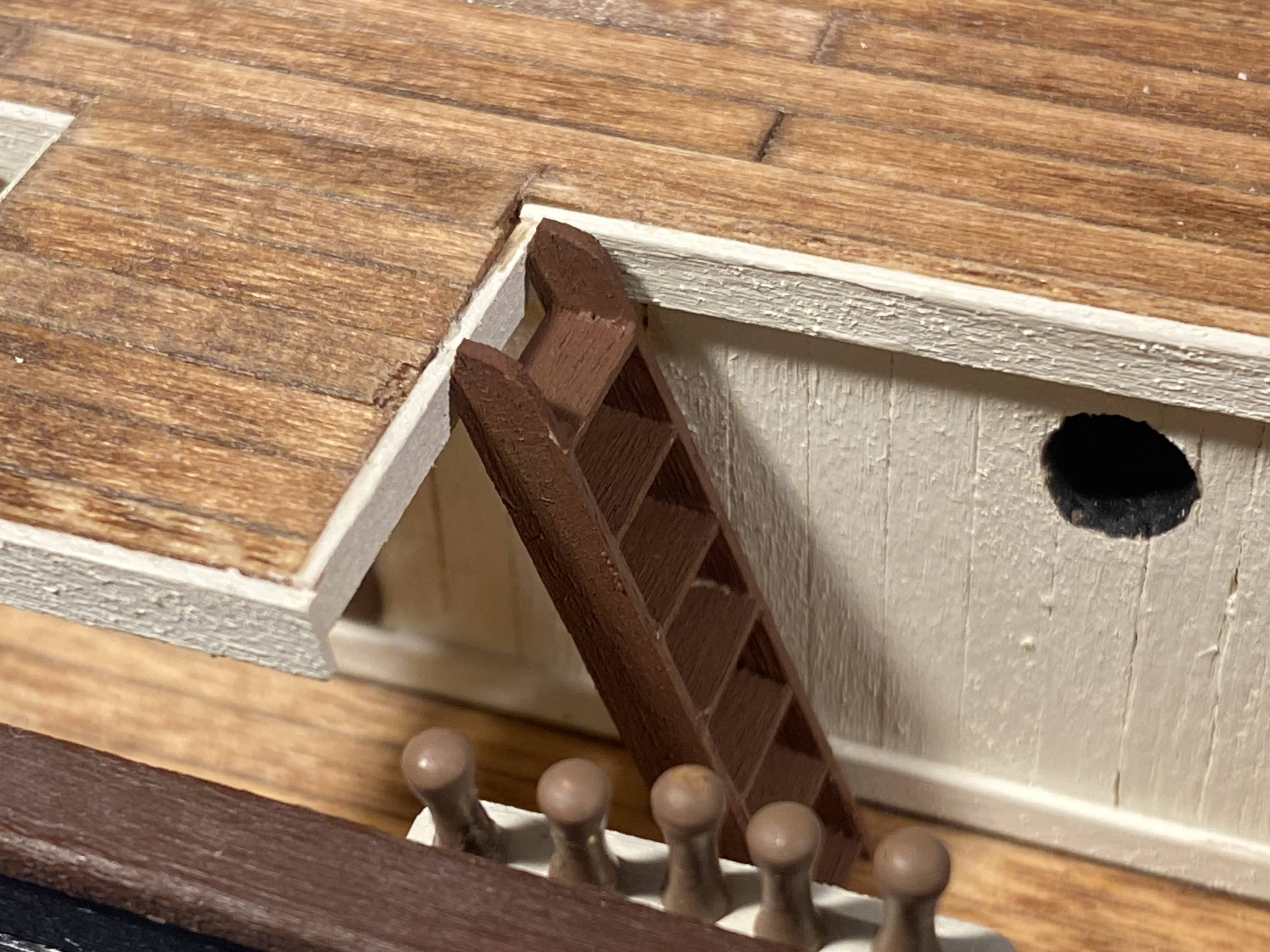
OcCre supplies at least a couple dozen tiny photo etched pieces to make Endurance’s ladders. I detached a few of those pieces and tried working with them, then like @theoracle09 decided I would make my own ladders out of wood. Over 40 steps had to be cut, but that was easy, much easier than cutting them out of the brass plate they came in and then filing down the attachment tabs. I also decided to make my steps (or treads) about 30% shorter, making the assembled piece narrower and looking more like a ladder than a staircase. The photo below shows the jig I made from pieces of scrap I had lying around. Although it can't be seen in the photo, the slide in the middle is sloped at the front, so that the individual steps will be glued in place at the correct angle. The first ladders I made were the short ones at the stern. Once glued together and I pulled the first one out of the jig, I realized that I hadn’t slid one of the rails all the way forward in the jig, resulting in rails that were misaligned by about a millimeter. But I also saw that the plans I so often refer to, and the cutaway drawing I have posted previously, show only one ladder back there, just to the starboard of the companionway. It was my good fortune to make my big mistake on a ladder I wouldn’t need! OcCre’s rails are parallelograms, meaning that the top of the ladder meets the wall it rests against at a sharp point. I cut the top of each rail so that that juncture was a short flat surface. I then rounded the opposite point at the top, all with a goal of making the tops of these ladders look a bit more realistic. Somewhat difficult to describe, but should be evident from the one close-up photo below. The ladders to the roof of the deck house are not glued in place yet since the deck house isn’t glued in place yet.


- 206 replies
-
- 7
-
-
- Endurance
- Shackleton
- (and 2 more)
-
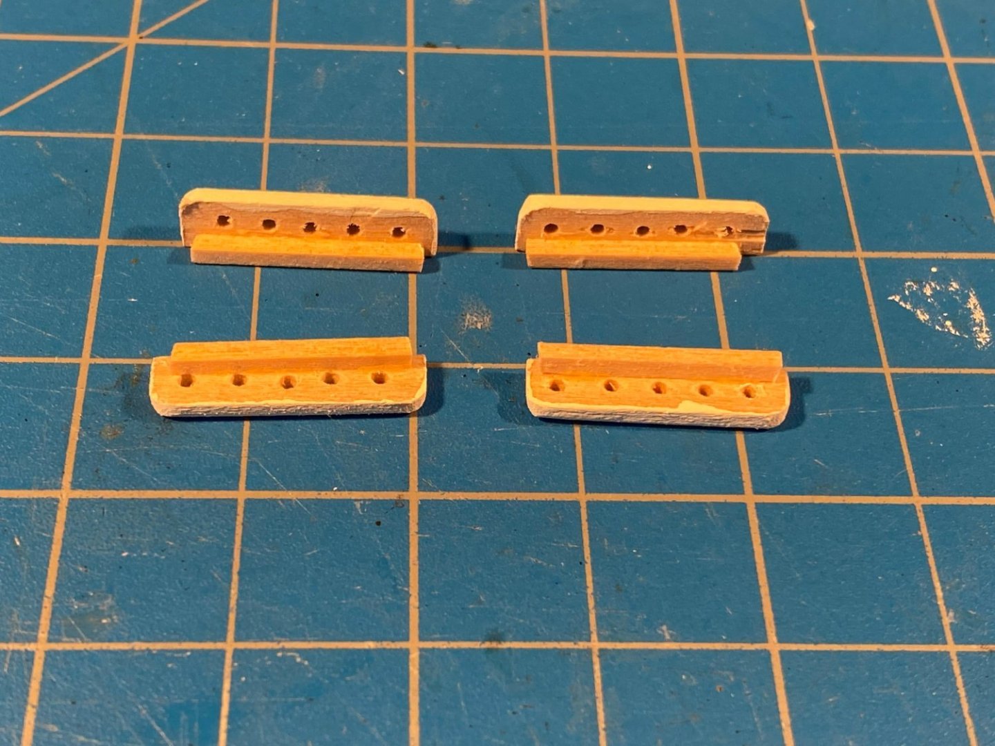
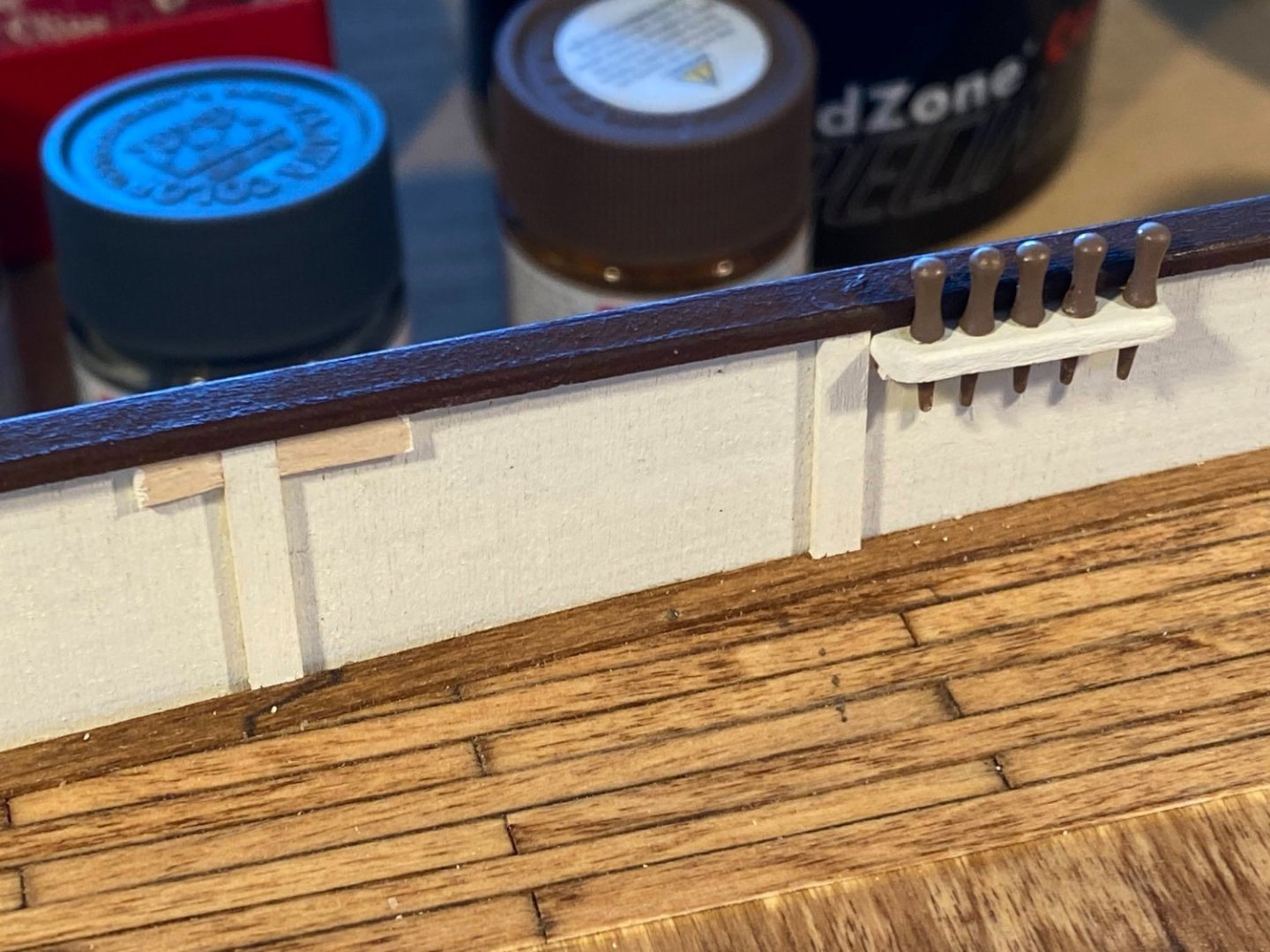
Thanks Josh. To answer your questions . . . My last build was Model Shipways cross section of the Constitution, and MS supplied 2 or 3 dozen photo etched brass hooks in two sizes. For whatever reason I only used about half of them. When it comes to left over fittings and supplies from old builds, I tend to keep everything, and these hooks were exactly what I wanted. I initially made a bow pin rail with holes for six pins, but it appeared that many close together would be problematic when it came to belaying lines on them. I decided to go with five pins instead, figuring I could either double up on one pin or omit one line. Only time will tell whether that was a wise decision.
- 206 replies
-
- 2
-
-
- Endurance
- Shackleton
- (and 2 more)
-
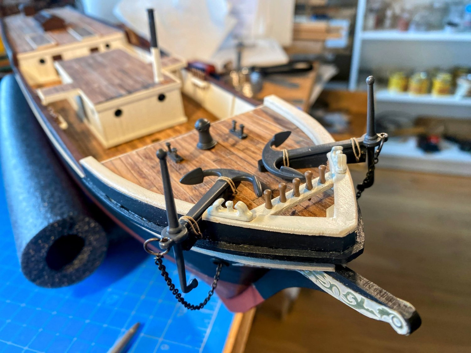
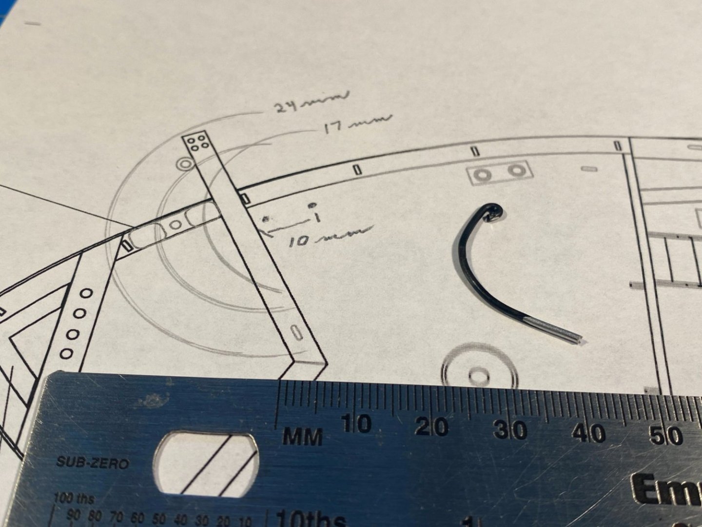
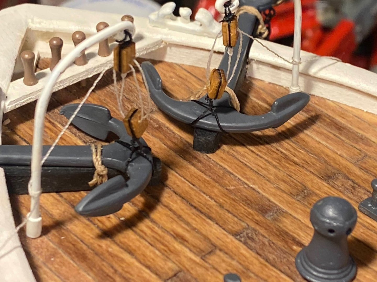
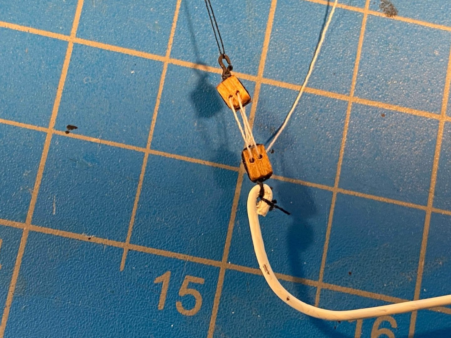
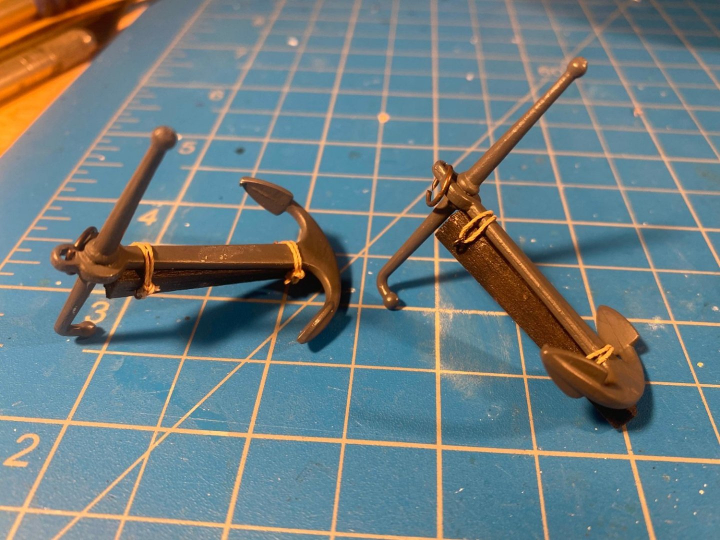
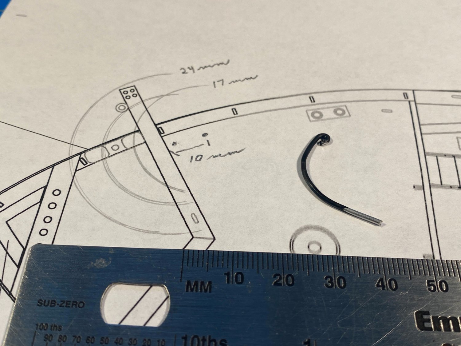
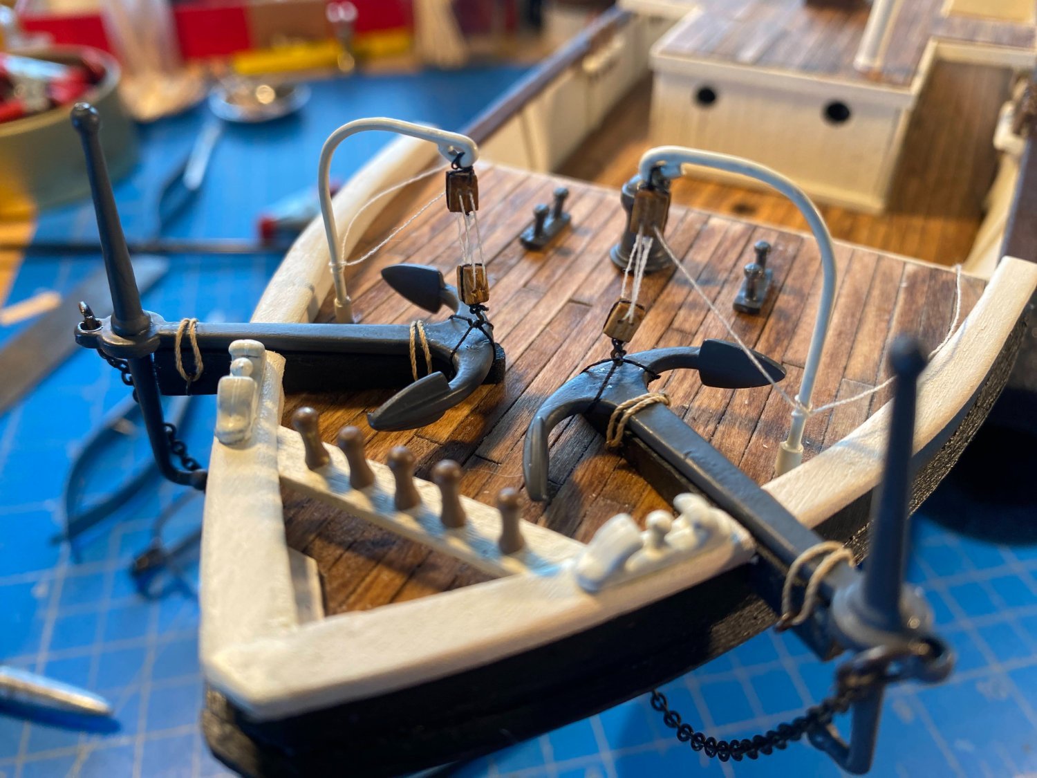
I found some relatively thick but malleable wire that I bent to create a couple of simple anchor davits. Using a drafting compass I determined what I thought would be the right size and location for a davit to accomplish its intended purpose. Then I used double blocks to rig a pair of “fish tackle” as described in my prior post. Unfortunately in my excitement to get this done (or perhaps I was half asleep before my first cup of coffee?), with one tackle I rigged both blocks backwards. I haven't re-rigged that one yet, recognizing that sometimes stupid mistakes are best corrected after a bit of a cooling off period. 😃 In the photos below, the port davit (with the incorrectly rigged tackle) hasn’t been glued in place yet. I made a bit of a base for each davit by wrapping some masking tape around the davit before painting them. The tackle tails are only loosely tied around the davits, awaiting my determination as to whether I can buy, or need to fabricate, tiny cleats to secure them to.

- 206 replies
-
- 7
-
-
- Endurance
- Shackleton
- (and 2 more)
-
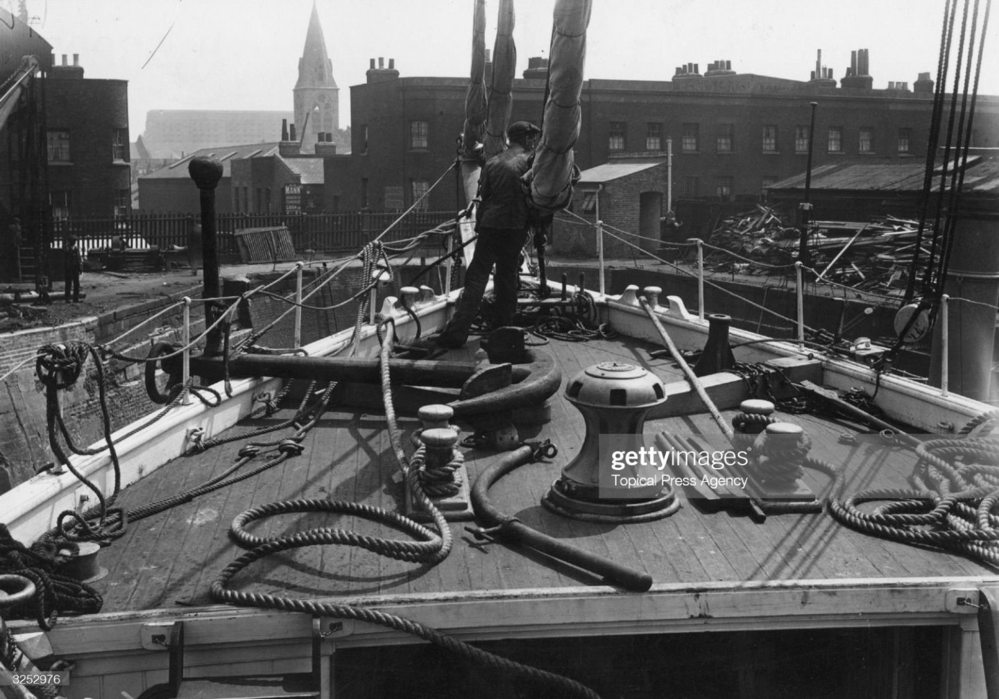
Several days of unseasonably beautiful weather, then a bit of spontaneous travel, have kept me away from both the shipyard and my computer . . . Posts by John ( @Jim Lad), Keith ( @clearway) and George ( @gak) inspired me to do some more research about anchors and anchor storage during the time of Endurance. If no one makes it to the end of this long winded and slightly off topic post, I won’t be offended. For centuries leading up to the 20th century, anchors were stowed lashed to the bulward and alongside the hull, with the shank more or less horizontal. On weighing anchor, once the head broke the surface, a tackle was hooked to the anchor ring, and the head was brought up level with the bulwark rail. The tackle ran through sheaves at the outer end of the cathead. A line from somewhere aloft was affixed to one of the anchor flukes, and that end was then also brought up more or less even with the bulwark rail, and the anchor was then lashed to the ship. There are probably thousands of photos on these boards of anchors so stowed. Here are a couple of my photos, the first being from my build of the Niagara, done quite a few years ago, and the second being the bow of Surprise, one of several ships at the San Diego Maritime Museum, built for the movie Master & Commander, being the leading ship in Patrick O’Brien’s fabulous series of maritime novels (this picture was taken about 5 years ago). Quite a few years ago I was browsing through a catalog from Dover publications, and I ended up buying a couple of old maritime books, The Art of Rigging by George Biddlecombe, and The Seaman’s Friend: A Treatise on Practical Seamanship, by Henry Dana, Jr. The latter was first published in 1879, and it contains the following description of what I just described. Its use of maritime terminology and late 19th century English is fun to read! I added the footnotes, but the notes’ text is from the glossary Dana put in his book. TO CAT AND FISH AN ANCHOR -- When the anchor is lifted and brought under foot, paul the windlass, keeping a good hold on the chain. Overhaul down the cat-block and hook it to the ring of the anchor. Stretch along the cat-fall and all hands tally on. Set taut on the cat-tackle and pay out a little chain. Hoist away the anchor to the cat-head, and belay the fall. Pass the cat-stopper through the ring of the anchor, through the chock, belay it to the cat-tail, and seize it to its own part. Overhaul down the fish-tackle, hook the lower block to the pennant, and hook the fish-hook to the inner fluke of the anchor. Rig out your fish-davit1 across the forecastle, and put the bight of the pennant into the sheave-hole. Get a guy over it, near the outer end, to keep it down, and another at the inner end, to keep it out. Get the shoe2 over the side, to fend off the bill of the anchor. Hoist the fluke well up, pass the shank-painter under the inner arm and shank, bring it inboard, and belay and stop it to the timber heads. Rig in the davit, unreeve the cat-fall and fish-tackle. 1. Davits. . . . Also, a spar with a roller or sheave at its end, used for fishing the anchor, called a fish-davit. 2. Shoe. A piece of wood used for the bill of an anchor to rest upon, to save the vessel’s side. Later in the 19th century, various forms of stockless anchors were developed, the most famous among recreational sailors currently being the Danforth anchor. Without a stock, the anchor shank can be pulled up into the hawsepipe, enabling the anchor to be stowed tight and flat against the side of the hull. No cathead, no davit, no line from aloft needed. What does this mean for Endurance? She carried a pair of old-fashioned stock anchors, but they were not lashed to the bulwarks as was so commonly done and as OcCre would have you do. Numerous Frank Hurley photos show one or both anchors lying on top of the catheads, with the flukes inboard and horizontal and the stock just outside the bulwarks rail, vertical with one end sticking up. In several of the photos that half of the stock rising skyward is all you can see of the anchor. A davit (as that term is used in contemporary times) would be needed to lift the anchor off the cathead and to swing the fluke end outboard so it could be lowered into the water. The only photo I have found showing such a davit on Endurance is the one in my previous post showing what certainly appears to be a davit, removable and lying on its side on the anchor deck. But there are photos of Endurance’s contemporary Antarctic explorer, RSS Discovery, with anchors stowed on deck on top of the catheads and with such davits in place. I am sure other ships did the same, but I don’t know how many there were or why. With all that in mind, I felt comfortable stowing my Endurance anchors on top of the catheads and installing davits to lift them off and on the deck when laying and weighing anchor. Those davits will be the subject of my next post. Finally, and not related to Endurance at all, I came across a fascinating YouTube video detailing the weighing of anchor on board the Star of India, the San Diego Maritime Museum’s magnificent clipper ship, when she was taken out for a rare sail. Lots of opportunities to lose a finger (or worse) manipulating that enormously heavy chain. Here’s the link.

.thumb.JPG.22d6b79e0e5219c240418af640a4ae55.JPG)

- 206 replies
-
- 3
-
-
- Endurance
- Shackleton
- (and 2 more)
-
Go for it Josh! There seems to be no argument that the real Endurance wasn't rigged that way. And as I increasingly find myself doing, I'll follow your lead when I get to that point in my build (which won't be any time soon).
-
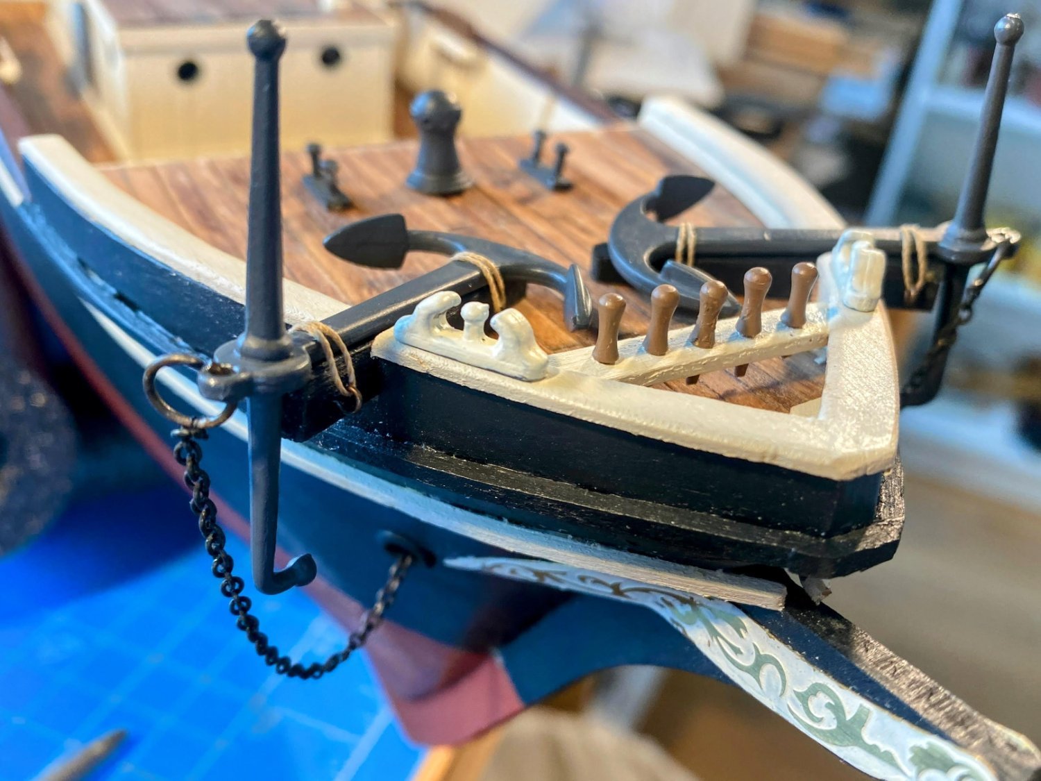
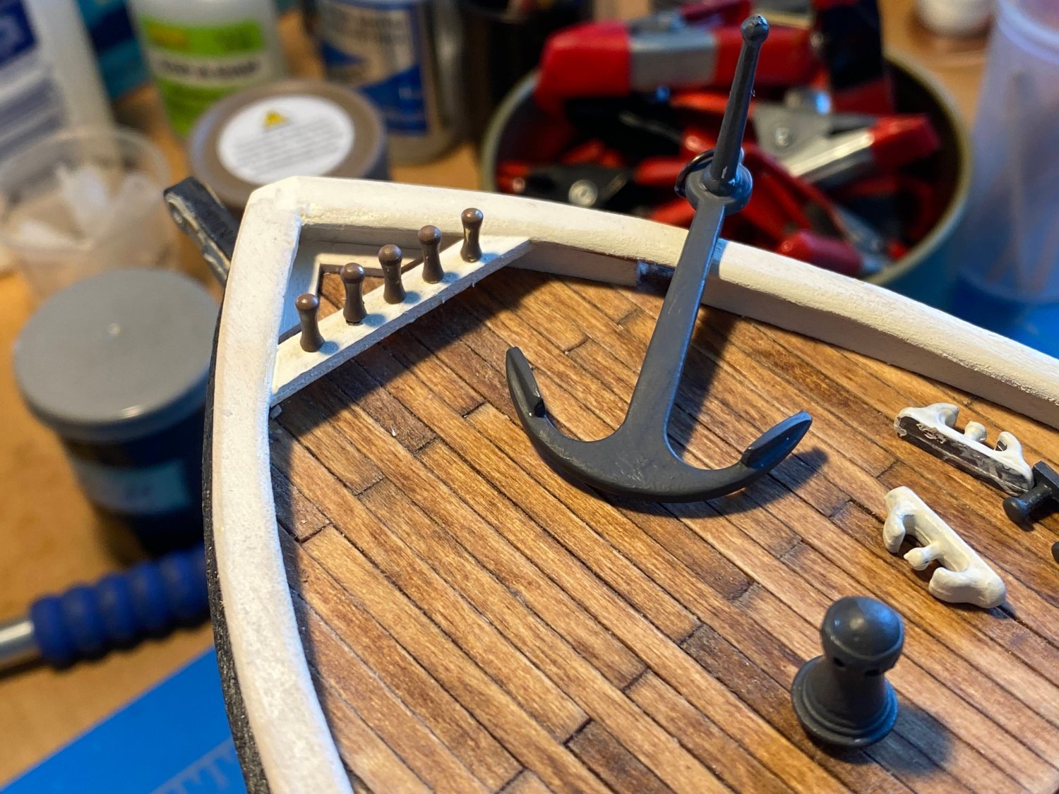
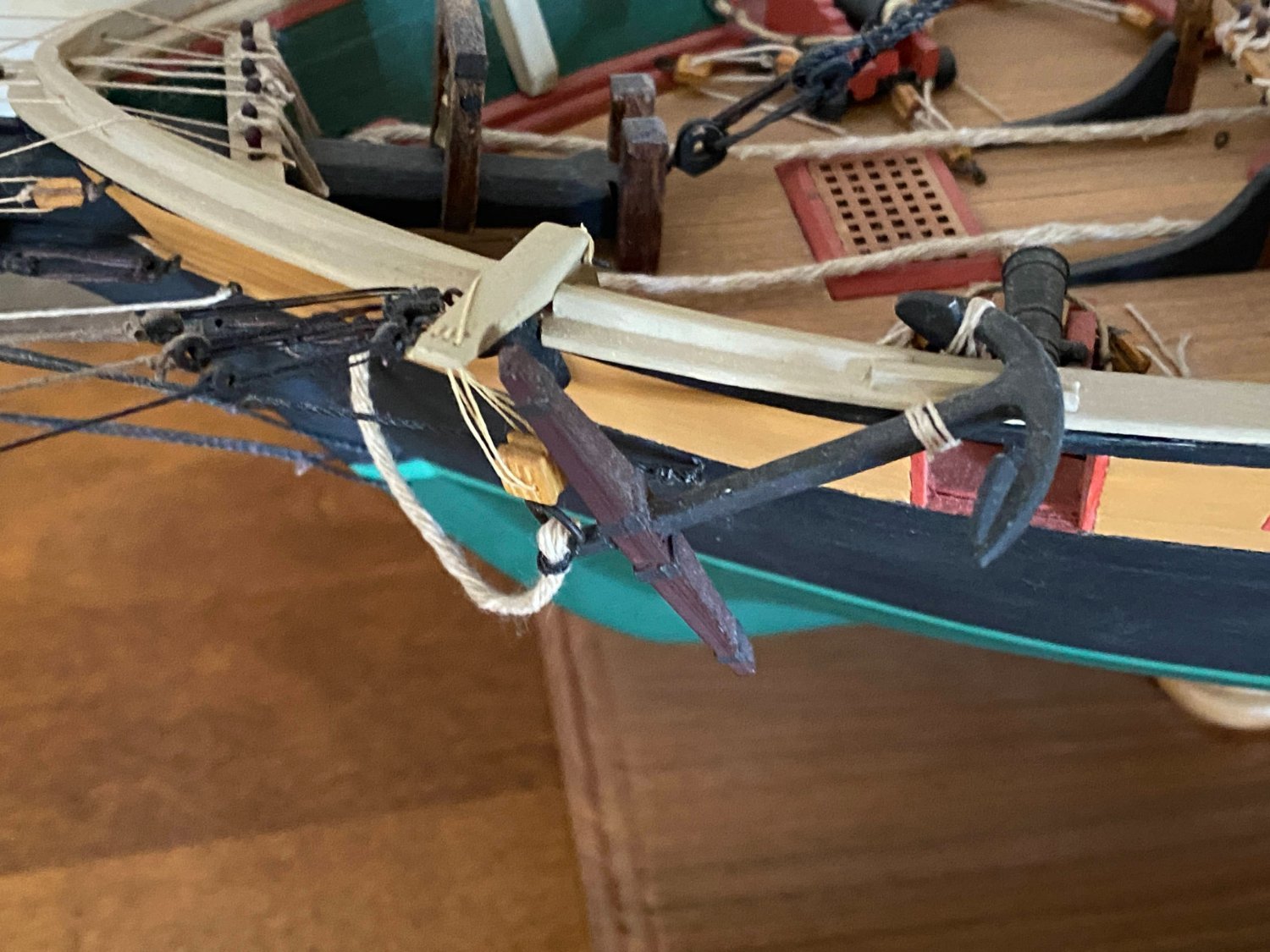
Most of what follows is informed by this Frank Hurley photo, which has appeared a number of times before in Endurance logs, including mine. I have modified the catheads and lashed the anchors to them. I shortened the catheads so they don’t stick out as far from the hull and don’t meet in the center of the anchor deck, as OcCre’s do. I also tapered them top to bottom as they progress inboard. After doing that, I noticed that the two plans I frequently refer to (see for instance posts #39 & #77 above) show the catheads meeting in the middle, so OcCre got it right for some period of time in the life of Endurance. Puzzling that that would be something changed at a later date. I also painted the catheads black, to match the color of the hull. I then installed two small eyebolts toward the inner end and outer ends of each cathead. The outer forward eyebolts are somewhat larger as they will also secure bowsprit stays. Then I cut gaps in the cap rail, so the anchors can lie directly on the catheads. In doing this I made a mistake. Since the catheads extend beyond the side of the hull, the stock of the anchor does as well. But looking closely in this and other photos, the anchor stock is secured up tight against the hull. This was done by securing the anchor at an angle to the cathead, with the stock and that end of the anchor lying aside rather than directly on the cathead. I wish I had noticed this sooner, but at this stage I am not going to go back and do it over. Finally, I cut the chain that has been hanging below the bowsprit for a few months to appropriate lengths and tied the ends to the anchor rings, using thin black fly-tying thread. I like this thread as it is strong and thin, almost indistinguishable from the chain. John’s (@Jim Lad) comment about “fishing the anchor” led me to do some research regarding anchors of this era. I am working on a somewhat lengthy post on what I’ve learned, as well as working on “fish davits” for the anchors.


- 206 replies
-
- 2
-
-
- Endurance
- Shackleton
- (and 2 more)
-
Very nice work on your Spray build. Especially nice to see it done by a fellow Washingtonian. It's always fun to see other builders' unique interpretations of a model I've built, and your build log was no exception. Congratulations on a job well done. You mentioned difficulty finding model paints anywhere nearby. The situation isn't much better here in Spokane, and I virtually always buy things like paint, additional wood, alternative fittings, tools and the like online. Not ideal, but there really isn't any alternative on this side of the state either.
-
Thanks George for your comments and photos. And kudos for taking on a scratch build of Discovery. I will be following closely. Glad to see that there are more photos than I had found of Discovery; they should be helpful to those of us working on Endurance builds. The photo you posted of Discovery is interesting, as the base of its foremast (and presumably the other two masts) has both a spider band (similar to that found on Endurance) and a more traditional fife rail. I have yet to find a photo of Endurance that shows a fife rail or a pin rail, which is puzzling. I’m hoping that someone will soon show me that I just haven’t looked hard enough.
-
Keith, what you describe about bringing the anchors aboard sounds very credible to me. You're a little farther along in your thinking than I am, but I had also reached the conclusion that a halyard from the foremast would be needed and that a davit alone wouldn't cut it. Josh, my wife is visiting her sister all this coming week, which means I'll be home alone with much more time to devote to my build than usual. With some luck I'll have those anchors installed and another installment posted by next weekend. 😀 Tom
- 206 replies
-
- 2
-
-
- Endurance
- Shackleton
- (and 2 more)
-
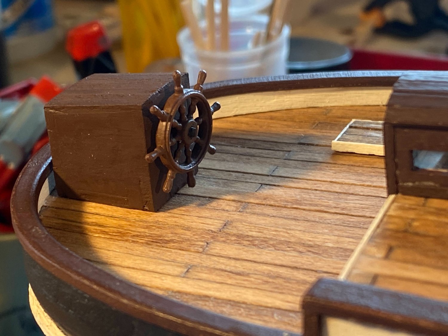
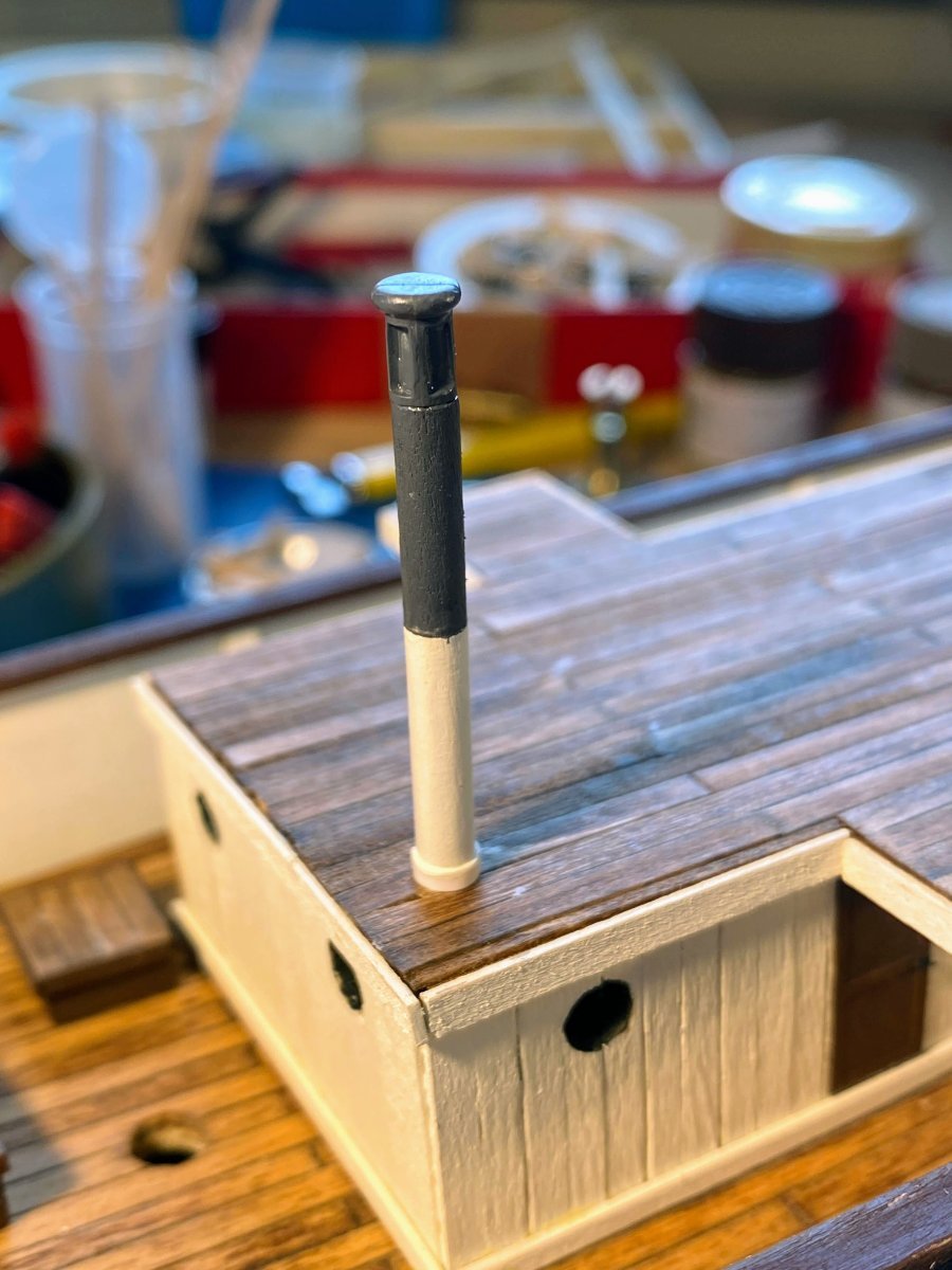
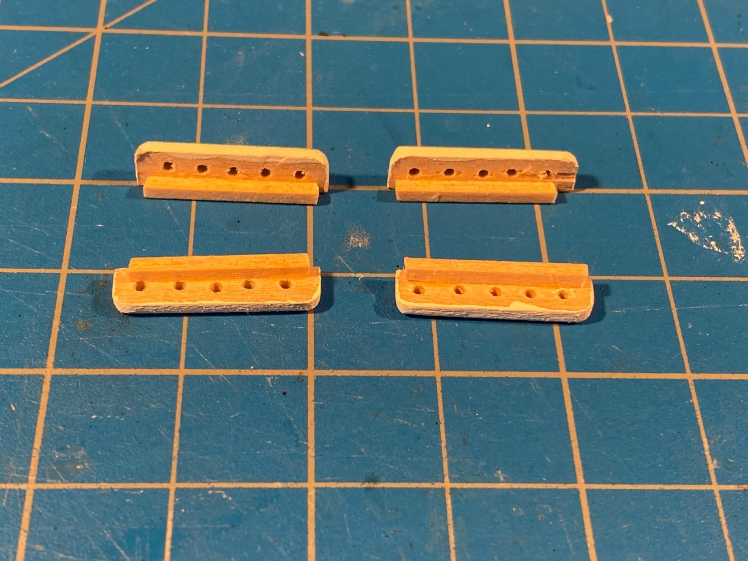
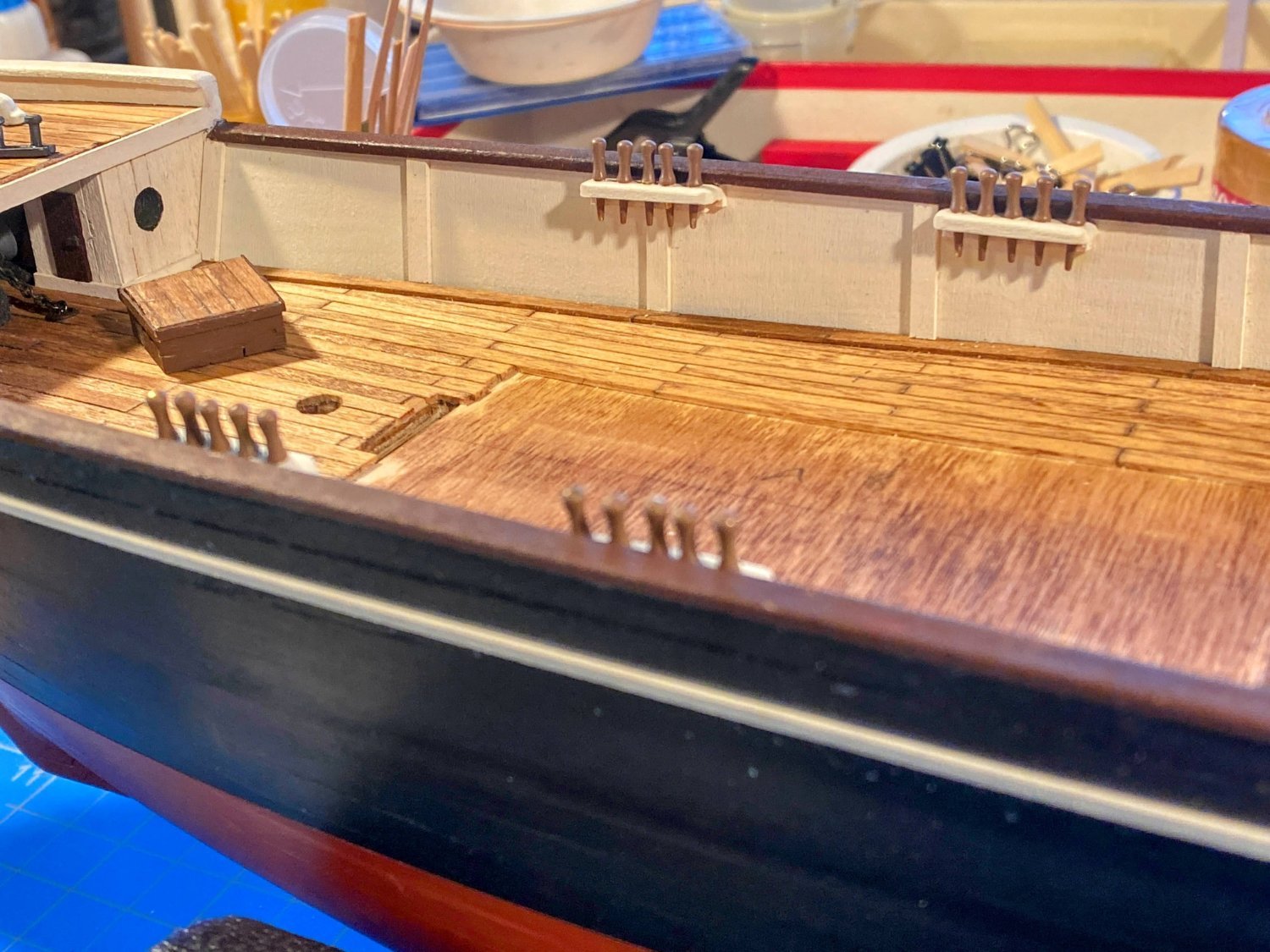
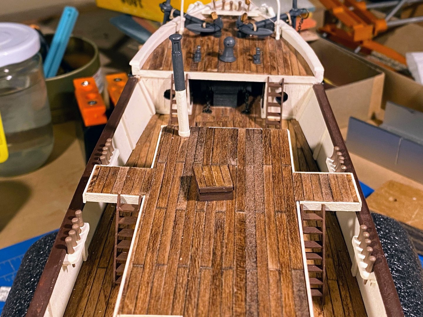
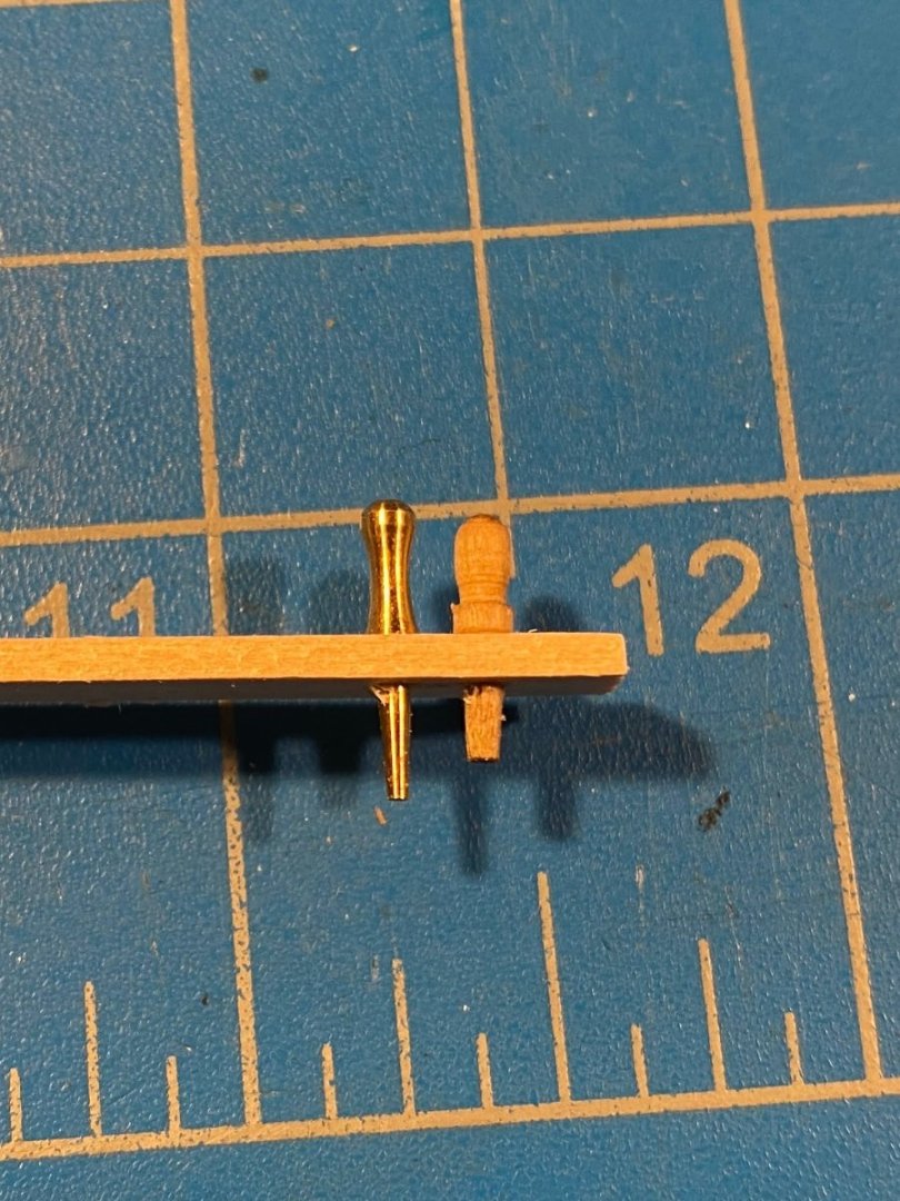
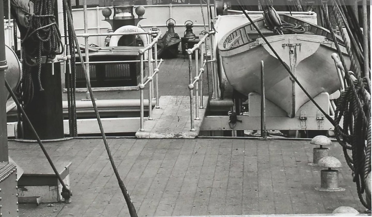
Some odds and ends . . . I built the steering enclosure using OcCre’s laser cut pieces, painted it dark brown, and found a slightly lighter brown for the ship’s wheel . . . a different color for no particular reason I can think of. Keith @clearway and Josh @theoracle09 have done a great job building and showing the steering mechanism, but for the most part I have tried to model Endurance before she reached the ice. I may be wrong, but it seems likely to me that the enclosure was built to protect the steering mechanism from the elements, which would include salt water, and that once the ship was trapped in the ice, and certainly after the rudder broke, that structure’s wood was better used elsewhere. But maybe that’s all rationalization for being a little lazy. Following the lead of Keith and Josh on their builds, I built a smokestack for the galley, which was located in the deck house. For the vent at the top, I used one of the fittings supplied by OcCre for the two misplaced (IMHO) smokestacks it would have you place in the aft corners of the lower deck (see discussion at the end of post #12 of this log). Again, being a bit lazy, I opted for the simple approach, and declined to emulate the beautiful metal work done by both Keith and Josh. OcCre provides for five pinrails, two on each of the bulwarks port and starboard, and one at the bow. It supplies nice looking wooden-appearing belaying pins, but I don’t think they look much like those used on Endurance, at least as they appear in the following photograph. Those belaying pins appear to be more like metal spikes. I had some brass belaying pins I purchased for and didn’t use on a previous build, and I decided to use those, being more authentic and likely easier to wrap rigging line around. In the final photo of my last post, I showed the bow pinrail lying on top of the rail caps and painted dark brown, as OcCre envisions it. But after looking at the Frank Hurley photo above, I made a new pinrail, painted it white, and glued it in more or less flush with the tops of the rail caps. I made the new pinrail by laminating two 1/32” thick strips together, with the bottom one extending slightly beyond the ends of the upper one, to be glued to the underside of the rail caps. I painted the brass pins a lighter brown (Tamiya's Flat Earth). Also, I had to cut the belaying pins a little shorter; otherwise they reached all the way down to the deck, which would make securing any line around them much more difficult. You'll also see that I have also assembled and painted the anchors. The bulwark pinrails need to be glued edgewise to the bulwarks, and that seemed a little flimsy to me, so I added a 1/16” square piece to the bottom of each one to provide a larger gluing surface. Also, the forward pair of pinrails each straddle a bulwark stanchion, meaning I needed to add short strips of wood so that there would be a surface to glue the full length of the rail to. As an aside, I don’t recall seeing any pinrails along the bulwarks in any of the photos, which makes me wonder how they secured running rigging that was not secured at the bases of the masts. If anyone has seen such a photo, I'd like to see it. I’m thinking that I won’t want to glue the deck house in place until after I have secured running rigging to these belaying pins, as there will be little space to work with the deck house there. Looking at the Hurley photo above again, I saw other changes I am working on at the bow. First the catheads are tapered, and they do not meet in the middle as depicted by OcCre. Also it appears that they run through a break in the caprails rather than under them; that is the way Josh did it and I like the look. Second, in the photo there is a small davit lying on the deck. I think I’m going to bend some wire and turn it into a pair of anchor davits, rigging them in place of the rigging OcCre shows going through the outer ends of the catheads. Endurance doesn’t appear to have had any rigging running through the catheads. Modern ships have their anchor shanks running up through a specially shaped hawse pipe, but that wasn’t the case on Endurance and earlier ships. I have always wondered exactly how ships’ crews brought their heavy anchors aboard, and once aboard, how they were safely stowed. Maybe I'll have a better idea once I have made and installed a pair of anchor davits.


- 206 replies
-
- 5
-
-
- Endurance
- Shackleton
- (and 2 more)
-
Very nice work Josh. And perhaps best of all, you sound really pleased and happy with the end result, something to be deservedly proud about.
-
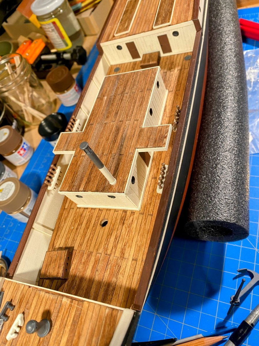
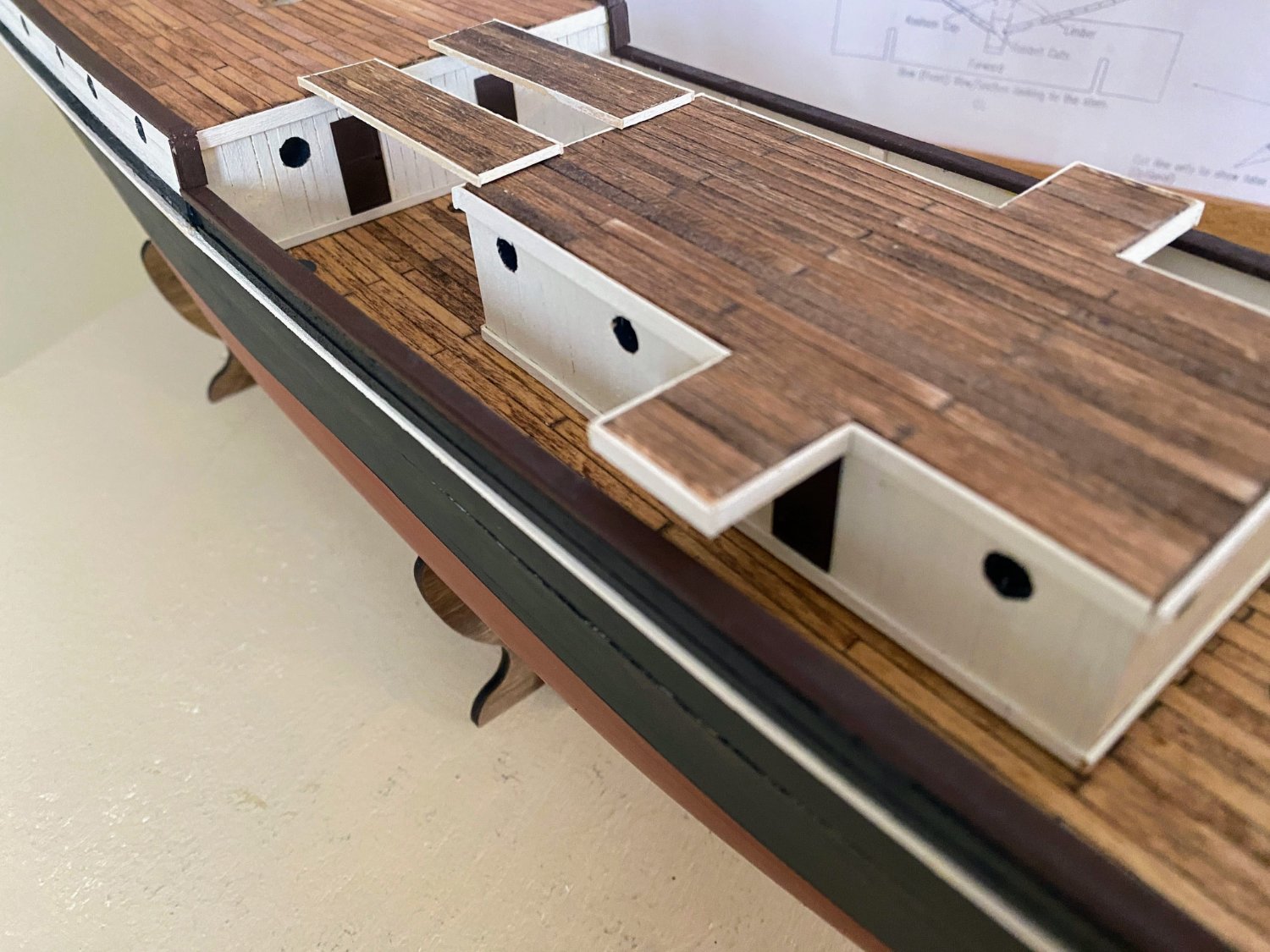
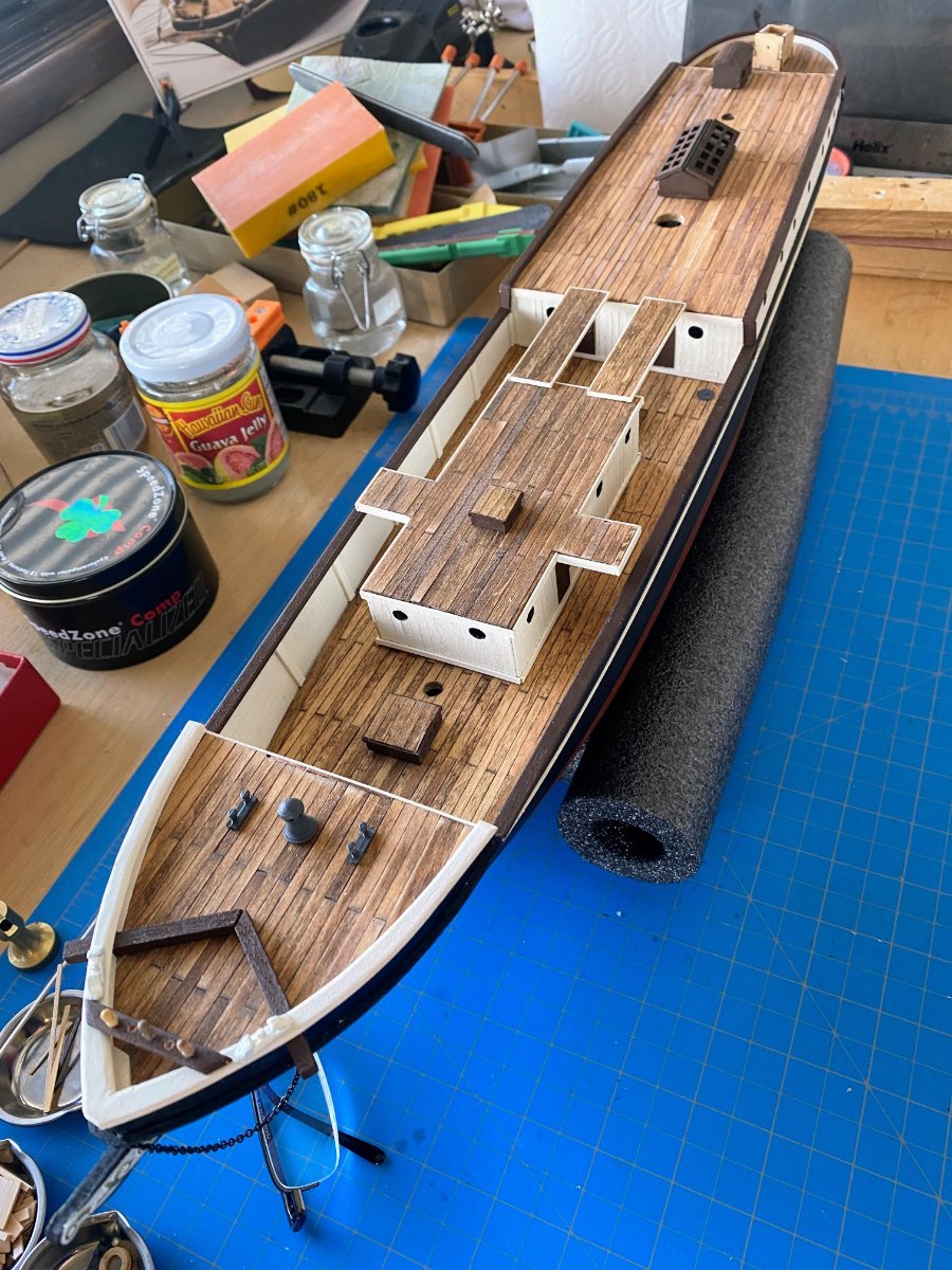
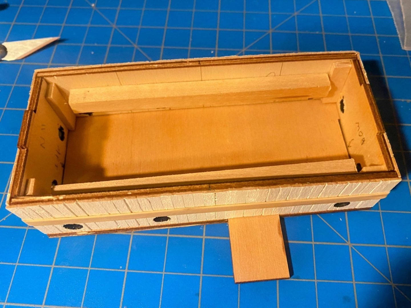
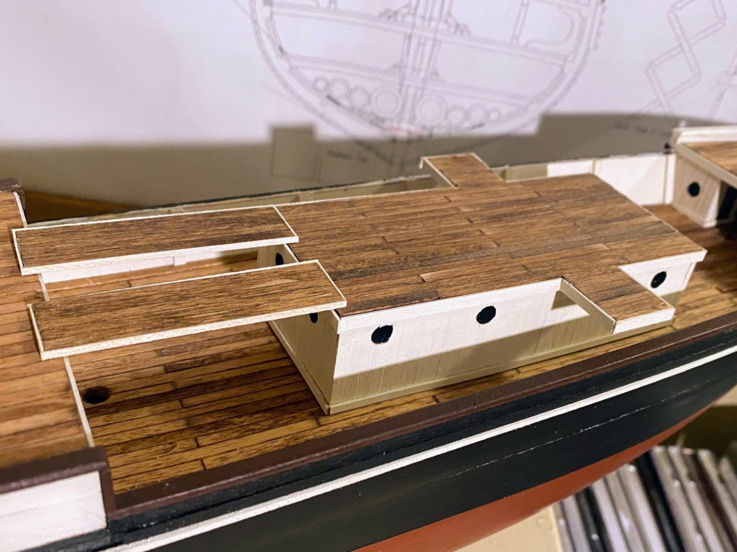
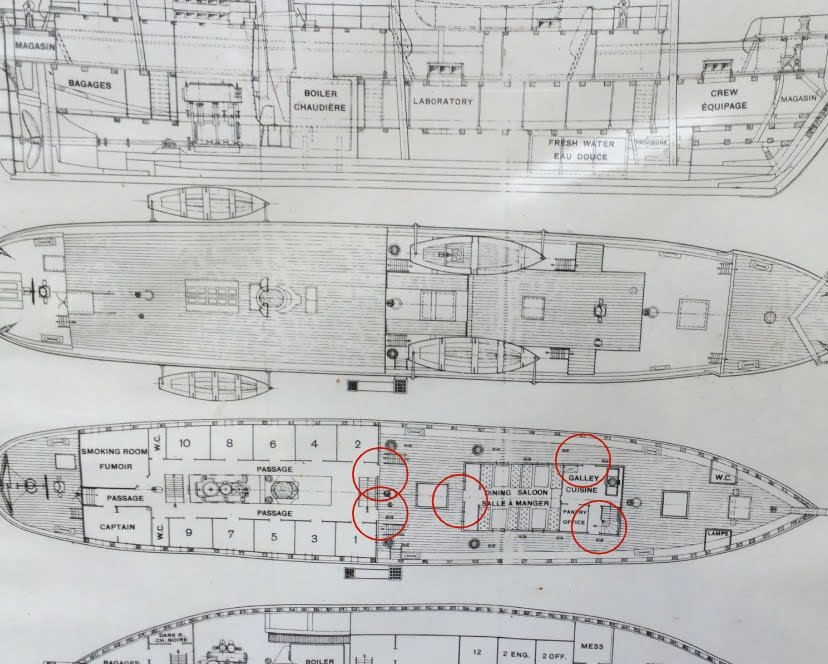
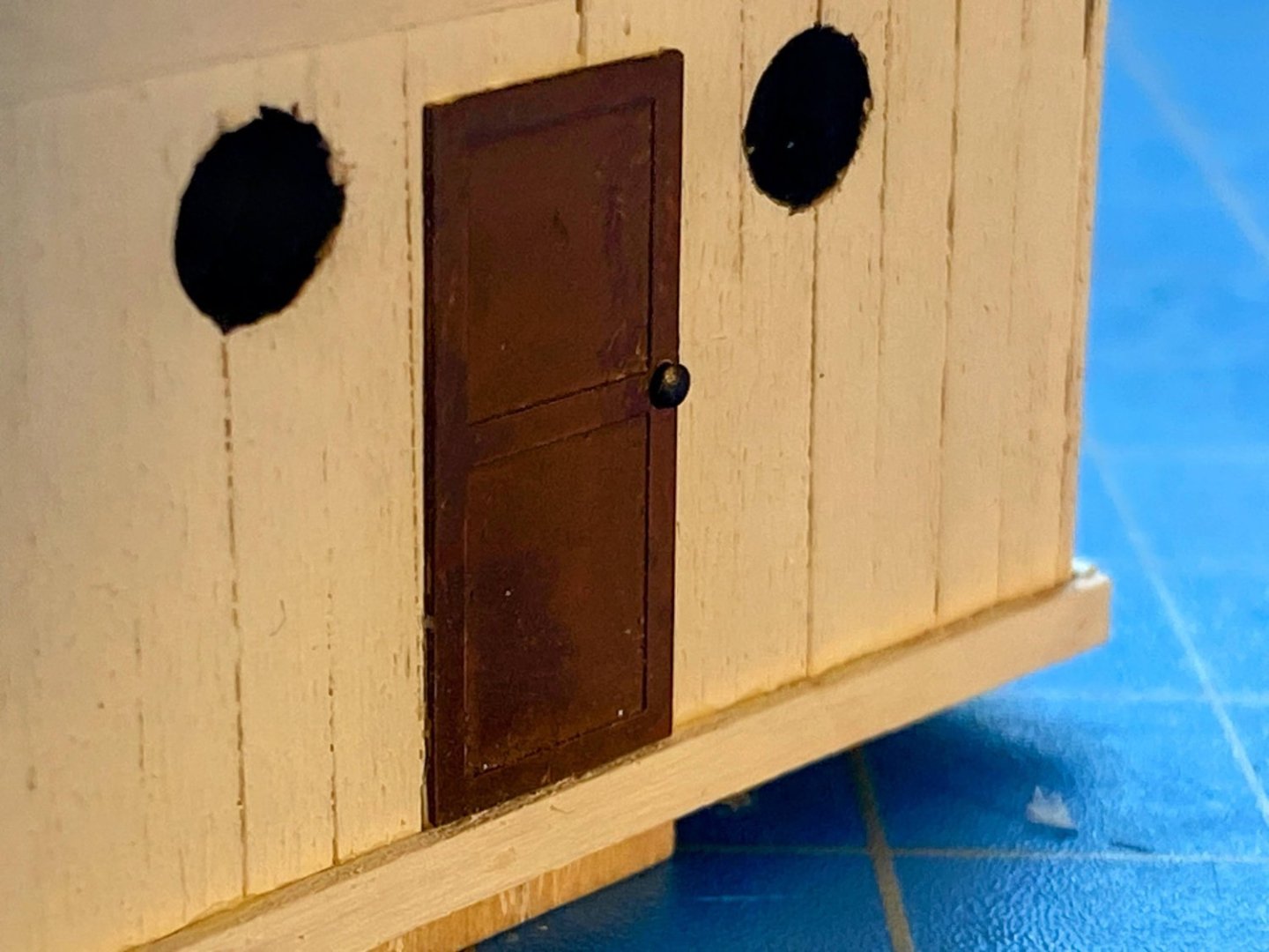
On to the deck cabin, with too much text and then some photos . . . I refer to the deck cabin as such because I haven’t come up with a better term. Some refer to it as the “Ritz”, but as others have pointed out, that does not appear to be correct. In his book, Ernest Shackleton describes new crew quarters, built “‘tween decks” to provide better protection from the elements at the onset of their first winter. I assume those quarters were built below the deck cabin, but I don’t really know; they may have been further aft. In any event, in Shackleton’s words, “The new quarters became known as the Ritz.” In these posts and other's in @theoracle09's log, Josh and Craig discuss the various ways the decking was extended around the deckhouse and between it and the deck behind it. Apparently the carpenters were kept quite busy on this ship. OcCre’s laser cut roof piece has small bridge decks on either side most of the way forward on the cabin, and two narrow extensions of the cabin’s roof deck back to and part of the deck aft. I decided (as did Josh) to go with OcCre’s design, with one exception. It seems clear (in the picture below and others) that those two planks were not extensions of the decks they connected but were separate, probably easily removable, planks or gangways lying on top of those two decks. So my first task was to cut off the extensions of the laser cut roof and fashion my own two planks. I made the planks from 1/16” strips, stained the same as the decks, and enclosed by veneer strips painted white. This would probably be a good time to explain something about measurements I refer to. OcCre, being a Spanish company, supplies wood cut to metric sizes. I have a large supply of wood left over from prior builds, and since almost all of my prior builds have been by American manufacturers, that supply of leftovers is almost entirely imperial. When I get a new build, I’m not very careful to keep the new wood separate from the old, and sometimes when I pull out what I think is a 1/16 by 1/8 strip, it may actually be 1.5 by 3mm. Having lived my entire life in the US, I think in terms of imperial measurements, even though intellectually I think the metric system is far better. The four sides of the cabin are laser cut, and they fit together nicely. Both longer side pieces were slightly warped inward, but that was easily remedied by gluing 3/16” square strips to the inside. The next bit of kit-bashing I did was planking all four sides of the cabin, consistent with the real ship; adding some trim around the roof and along the deck, and enlarging the portholes, painting the inside surfaces black. OcCre supplies six photo-etched brass doors, to be painted and affixed, one on the port side of the cabin, two on the starboard side, one on the aft end, and two on the bulkhead aft of the cabin. Based on the plans I downloaded from the Ernest Shackleton website, I determined that OcCre got it right, with one exception . . . there was only one door on the starboard side of the cabin. I painted the brass doors with Tamiya’s flat brown, added tiny nails painted black as door knobs, and glued them in place. The photo below shows some items I have placed on the foredeck. None of those things have been glued in place yet; in fact, the skylights and the deck house are also only dry fit. Securing running rigging at the base of the mainmast, and to a lesser extent to foremast, will be a lot easier without the deck house in place. Or perhaps I’ll rig the lines that terminate at the base of the mast before installing those masts. An issue for another day . . .


- 206 replies
-
- 4
-
-
- Endurance
- Shackleton
- (and 2 more)
-
While I am nowhere near as far along as you are Josh, I do find myself looking ahead pretty frequently, and I have the same question you do regarding the connection between the gaffs and the masts. I too was thinking of crafting some jaws and parrels, but after Keith's and Craig's input, I don't think I'll do that. Back when I was still working on my last build I came across the Shackleton Museum's large scale Endurance model, and it got me excited about Endurance as my next build. Imagine, a model of that scale to guide me through my build! But the more research I did, especially Hurley's photos, the less excited I became about the authenticity of that particular model, and I have seldom looked at it since starting this build. Mr. Greenwood's build is an entirely different story. Imagine how thrilling it would be to have a model you built end up in a museum in a place as central to the history of the ship as South Georgia Island!
-
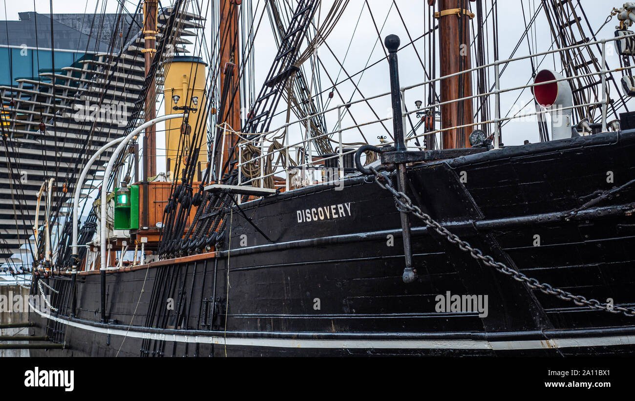
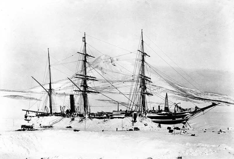
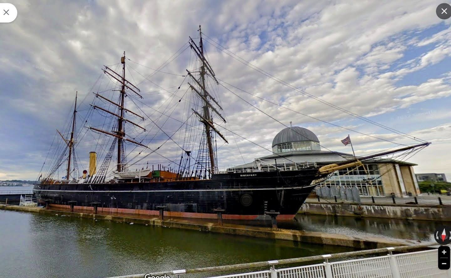
Digressing a bit . . . Several weeks ago, a question was asked here as to the authenticity of OcCre’s rigging of this ship, and @Jim Lad posted the suggestion quoted above regarding Robert Scott’s Discovery. Finally a couple of days ago I spent a short time searching the web to see what I could find out about Scott and his ship. Unfortunately I didn’t find (yet) anything helpful there to modeling Endurance, but the story I found is nevertheless fascinating. The two most helpful sources I found were a site maintained by the Dundee Heritage Trust and a site entitled Cool Antarctica. Discovery left for Antarctica in 1901, from the shipyard in which she was built in Dundee, Scotland. Like Endurance, Discovery became trapped in the ice and spent two winters there. Unlike Endurance, she was not crushed by the ice, and two ships found her after her second winter. With the help of explosives, she was freed from the ice, and she eventually made it back to the UK. Ernest Shackleton was third lieutenant on that Antarctic voyage. After a long career in many capacities, Discovery became a museum ship, back in Dundee. The second picture below is a screenshot of a Google Maps street view of Discovery as she is now Dundee. My wife and I spent some time in Scotland this past summer, and had I known then what I know now, there is no doubt we would have gone to see her. One thing I did learn concerns the appropriate terminology for these ships . . . Discovery is rigged as a barque; that is, the foremast and the mainmast are square rigged, with fore and aft sails on the mizzen. Endurance was a barquentine, with square rigged sails only on the foremast, and all other sails rigged fore and aft.
- 206 replies
-
- 6
-
-
- Endurance
- Shackleton
- (and 2 more)
-
Great work Josh on the cap rail and the stovepipe. I guess I first saw the latter in @clearway's log and completely forgot about it. Another fun bit of kit-bashing I can look forward to. And Keith, going back to look at your log, I see that you get credit for noticing the windows and curved roof of the aft companionway. Josh, I feel somewhat embarrassed when this past Thursday on my log I lamented the fact that you were no longer posting on your log anymore, when in fact two days earlier you resumed posting. I look forward to following you.
-
And I meant to add . . . I look forward to more posts on your log. Life does get in the way sometimes.
- 206 replies
-
- 1
-
-
- Endurance
- Shackleton
- (and 2 more)
-
Thanks Josh, both for the kind words and for the very helpful tip.
-
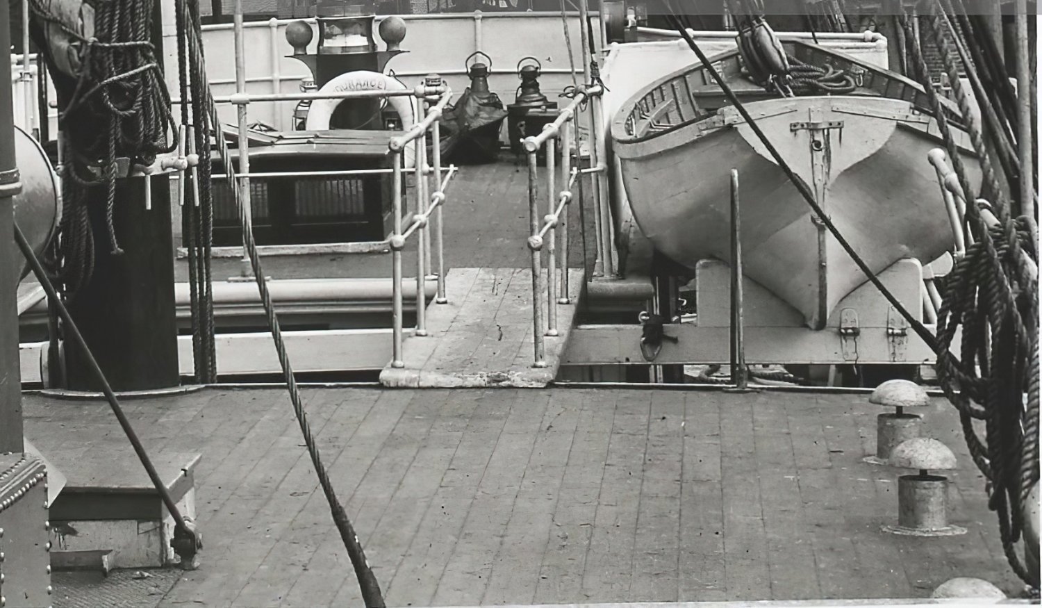
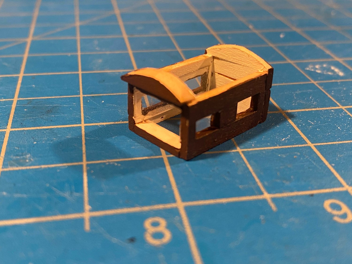
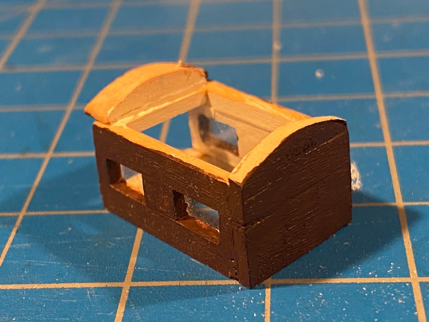
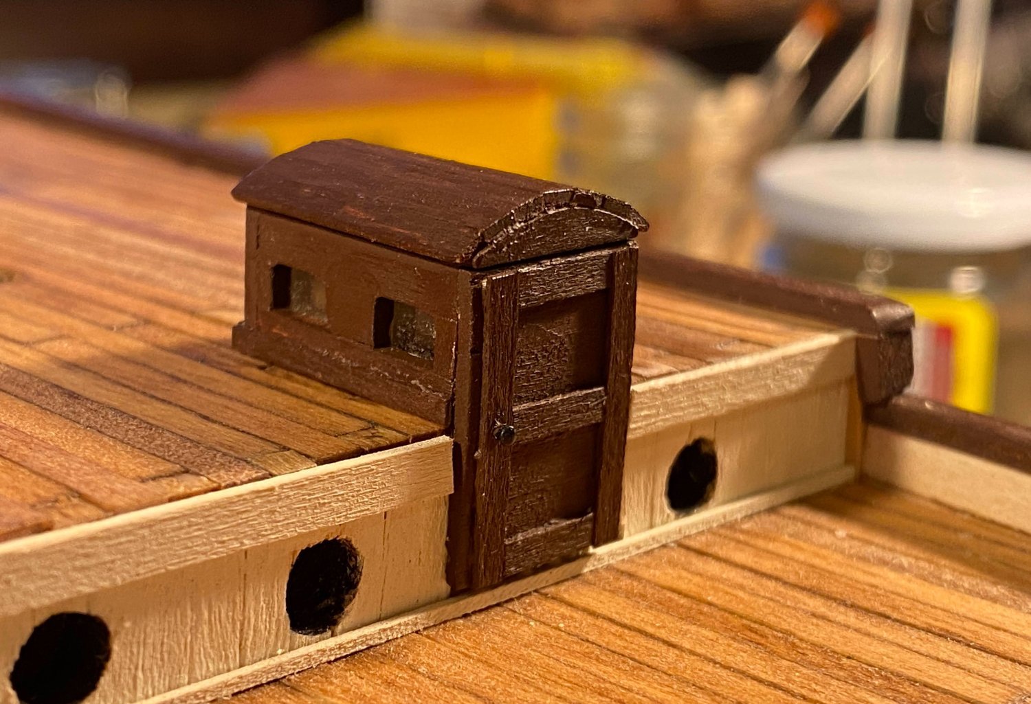
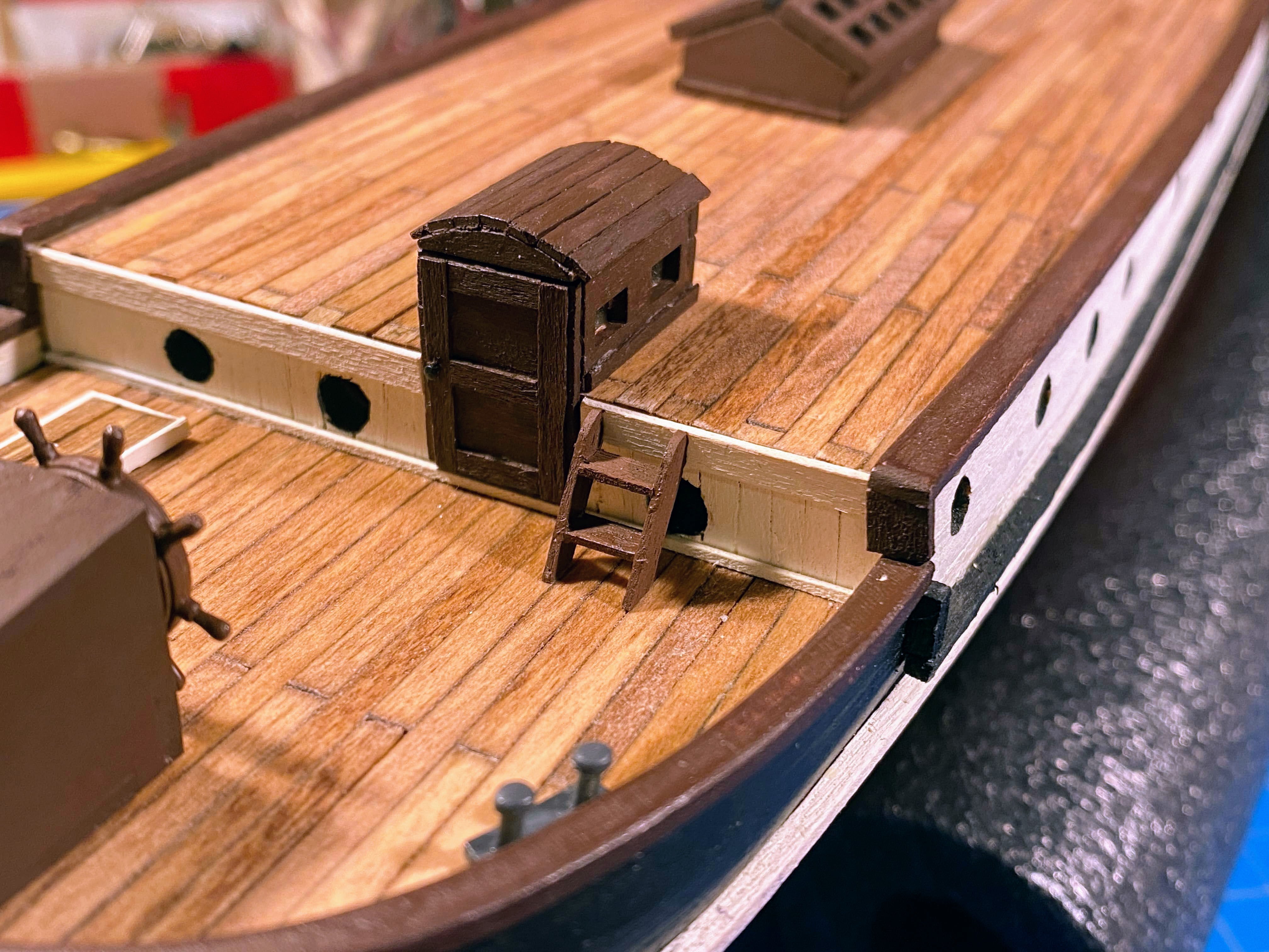
OcCre supplies laser cut pieces to construct a companionway in the bulkhead just ahead of the wheel. It has a flat roof with a sliding hatch. In his Endurance log, @theoracle09 (Josh) posted a photo (post #32) that shows a structure with windows, a slightly curved roof, and no sliding hatch. Post #33 by @iMustBeCrazy (Craig) has the photo zoomed in and shows these features more clearly. I decided I wanted to do what Josh (and presumably Craig) did, and I scratch built a structure more consistent with what that photo shows. As I did with the large skylight, I glued a strip of acetate on the back side of the windows and painted the inside white. One topic of discussion in Josh’s log (post #42) was whether the companionway has one door or two. Craig added a couple of additional photos and a drawing, in support of the view that there were two doors (OcCre’s view too). While the second of Craig’s photos clearly shows two doors, I think the first photo shows that at least at one point in time there was a single door. With that as my rationalization, I took the easy route and opted for a single door. The door is simply a slab made from 1/32” thick strips glued together edgewise, with additional, narrower, such strips for the trim. The door handle is a tiny nail, painted black. In retrospect I fear the entire structure is too tall, but I'm willing to live with that (since it is now firmly glued in place). It's about the size of what OcCre's would have been.


- 206 replies
-
- 3
-
-
- Endurance
- Shackleton
- (and 2 more)


.JPG.4a6aa6a2328bc6c4636858dedef97d36.JPG)