

Don9of11
-
Posts
718 -
Joined
-
Last visited
Reputation Activity
-

 Don9of11 reacted to Modeler12 in How to print a flag
Right on Don.
Here is another example of why it is important to keep the history and time frame of flags in mind.
For my next project I am going to build a small ship that was captured by the British from the French in 1776.
Even the British flags were different then from the current one. This could have been overlooked very easily.
From the way I read the information, the flag could either have a red or white background, but the diagonal red cross came into being in 1801 with the start of the United Kingdom. It represents the addition of Scotland. But that was not the case in 1776.
-
 Don9of11 got a reaction from mtaylor in How to print a flag
You're right. I found that getting the edges of the flag lined up and making sure the stripes and stars were in the same position was critical before the glue set up. The glue also provided a bit of moister in the paper that made working the flag a little easier. I researched carefully the era of my ship build, the Lucky Little Enterprise circa 1799, and made sure I had the right number of stars and stripes. I used different size dowel rods and following Chuck Passaro's advice, tried to get really aggressive with it. I tried a couple of different "wave patterns until I settled in on one that I really liked. It all boils down to being patient, deliberate and no fear.
Here is another photo from my work-in-progress collection.
-
 Don9of11 got a reaction from robnbill in How to print a flag
You're right. I found that getting the edges of the flag lined up and making sure the stripes and stars were in the same position was critical before the glue set up. The glue also provided a bit of moister in the paper that made working the flag a little easier. I researched carefully the era of my ship build, the Lucky Little Enterprise circa 1799, and made sure I had the right number of stars and stripes. I used different size dowel rods and following Chuck Passaro's advice, tried to get really aggressive with it. I tried a couple of different "wave patterns until I settled in on one that I really liked. It all boils down to being patient, deliberate and no fear.
Here is another photo from my work-in-progress collection.
-
Don9of11 reacted to Dan Vadas in How to print a flag
Yeah, how many times have you seen a model with full sails and the flags are flying toward the stern? They should be flying toward the bow if the wind is coming from behind.
All bets are off if the model is shown at anchor - the wind could be coming from any direction.
Danny
-
Don9of11 reacted to Modeler12 in How to print a flag
Nice job, Don. And it is good to know that it has held up well for you.
I assume that you made the adjustments before the glue stick kicked in. The waves look real.
The fifteen stars would indicate that your model is from the time that a couple more states were added (1795 - 1818). The fifteen stripes were also something new.
http://www.crwflags.com/fotw/flags/us-1795.html
I also like the thought that there are more than one way to skin a flag.
I recall there was also a good discussion here about the way or direction the flag should fly, depending on wind direction, speed, etc.
-
 Don9of11 got a reaction from CaptainSteve in How to print a flag
I printed mine using an inkjet printer on just plain copy paper. It was a double image, that is the flag had two halves or mirror copies. Once printed, I trimmed the flag and folded the paper then I used a glue stick to bond everything together. From there I just kept working it until I got the desired form I wanted.
These photos are about 5 years apart and though the background color is different (the gray background is more recent) the color of the flag has held up pretty well.
-
 Don9of11 got a reaction from Mfelinger in How to print a flag
I printed mine using an inkjet printer on just plain copy paper. It was a double image, that is the flag had two halves or mirror copies. Once printed, I trimmed the flag and folded the paper then I used a glue stick to bond everything together. From there I just kept working it until I got the desired form I wanted.
These photos are about 5 years apart and though the background color is different (the gray background is more recent) the color of the flag has held up pretty well.
-
 Don9of11 got a reaction from Modeler12 in How to print a flag
I printed mine using an inkjet printer on just plain copy paper. It was a double image, that is the flag had two halves or mirror copies. Once printed, I trimmed the flag and folded the paper then I used a glue stick to bond everything together. From there I just kept working it until I got the desired form I wanted.
These photos are about 5 years apart and though the background color is different (the gray background is more recent) the color of the flag has held up pretty well.
-
Don9of11 reacted to HSM in How to print a flag
I print them on regular printer paper and then over-coat them with flat clear to protect the ink from moisture. It takes a few tries to get the two sides of the paper registered but the results are worth it. I find the flags look better folded to represent light winds than they do when "flying". I see my avatar is the same image, but the only one I have in larger format online is a mix of two photos (same model).
-
Don9of11 reacted to Modeler12 in How to print a flag
Here is an old post that deals with making flags on cloth.
http://modelshipworld.com/index.php/topic/89-making-cloth-flags/?hl=%2Bmaking+%2Bflags
-
Don9of11 reacted to SJSoane in HMS Bellona 1760 by SJSoane - Scale 1:64 - English 74-gun - as designed
Hi everyone,
I have managed to cast my first cannon, more by luck than skill. Many thanks to Greg Herbert for the cypher; I have yet to accomplish a photo engraved cypher myself.
I learned a great deal, but will have to do this again, since the mould line between the two halves got a little ragged, leading to leakage and also a loss of detail at the join. Here is what I learned:
First, I built the initial mould box taller than the clay, which was a mistake. I was digging around from above to try to level the clay, and to push it evenly against the master. In hindsight, I see that the clay needed to be more accurately pushed up against the master. I didn't, and the first pour seeped down into the areas where the clay was not fully against the master, leaving a thin "flap" that prevented the second pour from coming cleanly against the master.
Next time, I need to build a first box at the level of the clay, then build higher walls to contain the first pour of rubber (the idea can be seen in the PDF about making moulds in the resources section of this website).
Second, I was using MicroMark rubber mould material that was 18 months beyond its shelf life. I don't know what it is supposed to be like within its shelf life, but one of the bottle's material was very stiff to stir at first. Indeed, I did not stir it enough for the first pour, and as a consequence it took overnight to dry and did not capture the detail as well as the second pour. I worked hard at mixing for the second pour, and added some thinner. The fidelity to the master was significantly better.
I used a bottom-up feed on the mould, with the understanding that the trapped air would be pushed out a vent at the top. I poured resin until I saw it bubbling out of the center vent. That method seemed to work flawlessly, with no captured air bubbles. However, I did notice a couple of pin holes in the top of the muzzle, which i assume were bubbles created when i poured the rubber onto the master. I poured a very thin stream rubber from over a foot above the mould into a corner, understanding that this would remove bubbles thicker than the stream, and that the material would slowly flow over the master. Worked almost, not quite! Perhaps my rubber material is too thick still, and needs more thinning.
If I am feeling experimental, I might try a top feed and see if it makes any difference or causes any difficulties. A top feed would certainly reduce wastage on the poured material. (I am in no rush, since I am still backing and filling, waiting for the Colorado humidity to come up in the spring so I can get back to building wales at the same humidity as the internal deck clamps.)
Back to the foundry for round two...
Mark
-
Don9of11 reacted to Kevin in Animated Knots
Someone might find this useful
http://www.animatedknots.com/knotlist.php?LogoImage=LogoGrog.jpg&Website=www.animatedknots.com
-
Don9of11 reacted to AON in HMS Bellerophon 1786 by AON – scale 1:64 – 74-gun 3rd Rate Man of War - Arrogant-Class
I believe I may have it now ... but I do not feel any smarter
(Thank to my ancestors I've got my good looks to fall back on )
Druxey suggested running plank lines or wire frame
My NRG mentor suggested buttock lines needed to be followed
I drew in buttock lines on my frames and then drew in faux plank lines
These showed my loft feature to be bumped out considerably on a couple places
I created new 3D profile / guide lines for the pulled in shape and lofted to these
It was still, somehow, not quite right. There were still bumps, albiet smaller ones.
I needed to divide the features more and create additional lofts of smaller areas to get it to pull in better.
The pink is the old shape and the green lines are the new shape before dividing it up more
Even after having done this all lines needed manual adjustments to blend better
Following is what I ended up with.
There are still minor deformations but at model scale and with sanding I believe these blemishes will disappear.
-
Don9of11 reacted to lonelius in HMS Bellerophon 1786 by AON – scale 1:64 – 74-gun 3rd Rate Man of War - Arrogant-Class
http://modelshipworld.com/index.php/topic/1163-learning-how-to-convert-from-2d-plans-to-3d-cad-build/?fromsearch=1
You should also check his reply in that topic. Looks so easy and right, but im still unable to get even close to that.
-
Don9of11 reacted to AON in HMS Bellerophon 1786 by AON – scale 1:64 – 74-gun 3rd Rate Man of War - Arrogant-Class
Had a busy time the last couple days.
Played with the upper transom outer corner some more and have 'flattened' it about as much as I dare.
Seems every other adjustment from there makes things worse somewhere else.
I managed to create a 5 second animation pan viewing the corner and also a PDF of incremental snaps shots automatically generated from the animation and sent it all to my NRG mentor to comment on.
Unfortunately I cannot seem to attach the .avi file here for the forum to view so here is the PDF.
lower transom shaping.pdf
I also manged (after considerable time ... it ended up being easier than I made it out to be) created a 36" x 60" sheet for my drawings in Solidworks.
I added 2D images from the 3D model at 1:48 and 1: 72 scale to be printed out to scale on Monday so I can better visualize.
HMS Bellerophon scales 1_48+72.pdf
That will be when I finally get off the fence and decide once and for all on a build scale.
I am / was (?) wanting to build 1:48 but am suddenly coming to realize the massive size this would be.
Possibly 1:72 might be more accommodating.
-
Don9of11 reacted to lonelius in HMS Bellerophon 1786 by AON – scale 1:64 – 74-gun 3rd Rate Man of War - Arrogant-Class
I wish Ppddry (http://modelshipworld.com/index.php/topic/1124-hms-pandora-1779-in-3d/#) was still reachable. His pandora hull looks so well designed, could be a really great source of tips if we could ask him how he made it.
-
 Don9of11 got a reaction from AON in HMS Bellerophon 1786 by AON – scale 1:64 – 74-gun 3rd Rate Man of War - Arrogant-Class
I like what I see Alan, nice work on the transom area. Your insights and discoveries have been very helpful.
-
Don9of11 reacted to Erebus and Terror in HMS Terror by Erebus and Terror - FINISHED - Scale 1:48 - POB - as fitted for polar service in 1845
NEW YEAR’S UPDATE
It has been a busy year for my project, though, unfortunately, much of my work hasn't translated into recent posts on Model Ship World. As most of you know, my project is really two in one: to create the first accurate scale model of HMS Terror as she appeared in 1845, and to produce the first accurate plans of the ship in her 1845 configuration. I spent much of the year on the latter, having decided early in the year to extend my plans to all decks and fittings of the ship. I completed a significant amount of this work, including the lower deck plans and details of accommodations (I’ve produced much more than has appeared here), and I am nearing completion of plans for the orlop deck and hold, as well as various cross sections. As always, creating these plans is not as simple as tracing the original Terror/Erebus plans, as each requires significant historical research to fill in the many missing gaps.
The discovery of HMS Erebus by Parks Canada also had a significant impact on my project. My blog was inundated with thousands of views and I received many dozens of emails from interested readers, researchers, and other enthusiasts. Many came during the exciting few weeks between the time the ship was discovered and when it was eventually identified. I enjoyed these exchanges immensely and they led to a blog post about the structural differences between the ships, which received a very positive response from many readers.
The discovery also led to several requests for consultation/information/plans from researchers involved in various media projects. I’m very excited by some of these new projects and while I can’t disclose them all yet, I’m sincerely gratified that my work will appear in formats other than my blog and posts on MSW. One of these has already come out; Canadian Geographic Magazine requested a modified version of my plans showing the most important ship systems. They did not utilize the entire plan, which included a cross section, so I have provided the entire image above.
Despite all of this additional work, I haven’t forgotten about my model, and I’ve been working slowly away at it when I can find a chance. Below I outline my progress to date:
Each scarph on the keel had 8 copper bolts, 1 and 1/8 inches in diameter (consistent with much larger 36 and
74 gun vessels). I simulated these using 20 gauge copper wire which accounts for a 1.5 inch rove.
Gluing the main keel and stem together. Alignment was critical, so the parts
were laid out over the plan and clamped/weighted down.
Checking the alignment before gluing. The unfinished profile piece can be seen in the background.
Gluing the pieces in place.
The completed keel/stem assembly with the false keel sections dry-fitted below. Each false keel section
was ca. 24 feet in length and 7 inches deep. I originally thought they were attached with staples,
but nails were more likely in this era.
Gluing black velum to the false keel sections to simulate tarred flannel.
Gluing the false keel to the keel assembly. Note the final shaping of the lower stem piece has not been completed.
The 1836 plans indicate that false keel thinned as it ran forward; here I've mark off its run prior to final sanding.
The completed piece. Unfortunately the fluorescent lights I'm using don't do the richness
of the Swiss Pear justice - indeed they make the wood look quite dry and pale when it actually is not.
A view of the simple false keel scarphs near the centre of the keel. The false keel was designed
to tear away in the case of a grounding and was essential on bomb, merchant, and exploration ships.
Note that this is the port side of the keel (fore is on the left).
Profile piece and station bulkheads cut from 1/4 inch plywood (no matter what I do I cannot get this picture to display
correctly - sorry!).
Cutting the slots for the station bulkheads.
Deburring with some wonderful scroll-saw sanding strips I purchased from Lee Valley.
The profile piece with all the bulkhead slots cut out. The fore and aft slots will be finished after the
keel is glued to the profile piece and the mast slots will be removed when the station bulkheads are all in place.
The keel assembly and profile piece prior to gluing.
The keel was pegged and glued to the profile section.
The pegs continued up the stem.
The keel assembly glued to the profile piece. Everything is square as far as I can tell - but the
clamping required was far too ugly to show here! The stern assembly will be fitted when the bolsters
for the propeller aperture are added and will need to be glued in the vertical position.
Captain Crozier inspects the boxing.
-
Don9of11 reacted to AON in HMS Bellerophon 1786 by AON – scale 1:64 – 74-gun 3rd Rate Man of War - Arrogant-Class
I looked at images of the Bellona transom which was better than most images in books I have
Then I adjusted the radius as much as possible, I believe, to reduce the sharpness in the turn at the corner
Following are two images, before adjustments and after
Druxey, is this "more better?" (as the young'uns say)
Alan
-
Don9of11 reacted to AON in HMS Bellerophon 1786 by AON – scale 1:64 – 74-gun 3rd Rate Man of War - Arrogant-Class
Thank you Druxey
I'll have a look at some photos from forum builds and books and then play with it some more.
Meanwhile I had extruded my keel and post sketch to the maximum thickness of 1-1/2 feet.
You can see the hull shape at the stern disappears into it prematurely. This is because the stern post is not a constant thickness but notched away and tapered. Same thing at the stem post but not as dramatic.
I included a couple snap shots with the keel and posts made a bit transparent so you can see where the hull disappeared to.
-
Don9of11 reacted to AON in HMS Bellerophon 1786 by AON – scale 1:64 – 74-gun 3rd Rate Man of War - Arrogant-Class
I created new planes at the different deck levels where the transom direction (shape) changes and drew my arc's in.
These ended up being 50.5 ft radius.
This was accomplished by inserting a "point" on the plane and then mating it via "pierce" to the earlier transom line from yesterday that passes through the plane.
I drew a center line on the plane passing through this point and then offset it the distance to the hull as measured off the plan.
Width measurements were:
roundhouse deck level = 20 feet
quarter deck level = 24 feet
upper deck level = 26 feet
The arc was trimmed back to the centre line on one side as I would only loft half the transom as the extending lines might confuse the loft feature.
I then added yet one more plane at the highest most elevation of the centre stern frame under the rail at 52'-6" and added another arc.
I then "connected the dots" of the extreme outer ends of the arcs using 3D sketch (I got this idea from Don's posting above)
This required some 3D manual fine tuning to blend the line into the shape of the hull
Once I had that where I thought I should stop I used the Loft Feature to fill in the shape.
I then added a few extra lines to allow me to lofted in the shape of the missing upper port aft part of the hull.
Now I need to complete the keel and posts.
-
 Don9of11 got a reaction from SgtSki in MI in First attempt at planking - need advice
I agree with Rich, it's good job. You put a lot of work into your model so I would plug the open seams with wood putty, sand it down a little and then move on, it will look just fine. In time it will become a conversation piece not because of the planking but because of your attention to the rigging, sails, deck fittings. Of course you could always paint it, paint hide a multitude of sins
-
Don9of11 reacted to Snowmans in Home Built Thickness Sander
The block on top was added after a month or so of using the sander as by then I was sick of the dust that it blew out. The hole is just the right size to fit the vac hose. With the vacuum attached all the dust is taken away, I don't even need to wear a dust mask while it is operating. The round cap is used to block the hole and also to check the condition of the sandpaper during use without removing the front cover. Here are a couple of extra pictures showing some of the details.
-
Don9of11 reacted to AON in HMS Bellerophon 1786 by AON – scale 1:64 – 74-gun 3rd Rate Man of War - Arrogant-Class
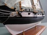
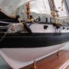
For those following and wondering what happened to my progress here... I have switched gears and have been working on the schooner CHARLIE for a friend.
Hope to be back to my first order of business early in the new year.
-
 Don9of11 got a reaction from bago100 in First attempt at planking - need advice
I agree with Rich, it's good job. You put a lot of work into your model so I would plug the open seams with wood putty, sand it down a little and then move on, it will look just fine. In time it will become a conversation piece not because of the planking but because of your attention to the rigging, sails, deck fittings. Of course you could always paint it, paint hide a multitude of sins