

Don9of11
-
Posts
718 -
Joined
-
Last visited
Reputation Activity
-

 Don9of11 got a reaction from WackoWolf in Making sense of Zebra View in SolidWorks
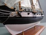
Here is an example of a Bounty class launch that has a perfectly shaped elliptical hull. In the real world you would never see this, at least I don't think you would. I would think you would see symmetry on the view of the bottom hull but that must depend on the position of the cube and the mirrored surface of the boat. The lines do flow all together so this hull is smooth.
I think this could be a good visual tool to easily see bad spots in a hull but ultimately its going to be the traditional measurement of waterlines, buttock lines, etc. that determine the fairness of the hull.
-
 Don9of11 got a reaction from jud in Making sense of Zebra View in SolidWorks
Here is an example of a Bounty class launch that has a perfectly shaped elliptical hull. In the real world you would never see this, at least I don't think you would. I would think you would see symmetry on the view of the bottom hull but that must depend on the position of the cube and the mirrored surface of the boat. The lines do flow all together so this hull is smooth.
I think this could be a good visual tool to easily see bad spots in a hull but ultimately its going to be the traditional measurement of waterlines, buttock lines, etc. that determine the fairness of the hull.
-
 Don9of11 got a reaction from AON in Making sense of Zebra View in SolidWorks
Here is an example of a Bounty class launch that has a perfectly shaped elliptical hull. In the real world you would never see this, at least I don't think you would. I would think you would see symmetry on the view of the bottom hull but that must depend on the position of the cube and the mirrored surface of the boat. The lines do flow all together so this hull is smooth.
I think this could be a good visual tool to easily see bad spots in a hull but ultimately its going to be the traditional measurement of waterlines, buttock lines, etc. that determine the fairness of the hull.
-
Don9of11 got a reaction from jud in Making sense of Zebra View in SolidWorks
If I understand Zebra lines, they represent the smoothness of a surface. In the top view, my ship the lines are all contiguous until you get to the dead flat and just forward of that the zebra line gets smudged out. The same is true for the bottom view. This indicates there is a problem, a dent or some other deviation. The same thing can be seen in the aft part of the ship near the keel and other areas if you pay close attention. Wherever the zebra lines break or fail to merge together smoothly there is some kind of deviation in the hull and in fact by measuring various points along the waterlines (not shown here) I do indeed have issues with the frames just forward of the dead flat and probably in other areas as well.
As with anything you see for the first time, its difficult to determine the significance of the zebra lines without a comparison to a goodly faired hull. If one could scan the hull of a real ship or even an admiralty model we might be surprised at the results. For all I know the pattern of these lines might be acceptable at the scales we build our ships.
-
 Don9of11 reacted to Lizzy Borden in need Help enlarging image to start first kit over
Excellent info. I had a play about with this today using a free program called Inkscape. Did exactly what I wanted it to do and these are the resulting templates for the superstructure I scanned from HMS Andromeda as an experiment.
Scale is spot on, and from the files saved as SVG I can now make the model any size I want.
Gary.
-
 Don9of11 got a reaction from flying_dutchman2 in need Help enlarging image to start first kit over
If you decide to scale the drawing using some scanning/enlarging method and the lines get thicker just work to the center of the line. My reasoning is that years ago drawings were drawn in pencil, very lightly and then draftsman would "ink" over the lines. The pencil line acted like a center line and measurements were taken from the center of the line to the center of the next line, never to the outside or inside. This reasoning can be applied to lines that get bigger by enlarging.
-
 Don9of11 got a reaction from Q A's Revenge in need Help enlarging image to start first kit over
If you decide to scale the drawing using some scanning/enlarging method and the lines get thicker just work to the center of the line. My reasoning is that years ago drawings were drawn in pencil, very lightly and then draftsman would "ink" over the lines. The pencil line acted like a center line and measurements were taken from the center of the line to the center of the next line, never to the outside or inside. This reasoning can be applied to lines that get bigger by enlarging.
-
 Don9of11 got a reaction from 42rocker in need Help enlarging image to start first kit over
If you decide to scale the drawing using some scanning/enlarging method and the lines get thicker just work to the center of the line. My reasoning is that years ago drawings were drawn in pencil, very lightly and then draftsman would "ink" over the lines. The pencil line acted like a center line and measurements were taken from the center of the line to the center of the next line, never to the outside or inside. This reasoning can be applied to lines that get bigger by enlarging.
-
Don9of11 reacted to AON in HMS Bellerophon 1786 by AON – scale 1:64 – 74-gun 3rd Rate Man of War - Arrogant-Class
It has been a few weeks since my last post.
I had suffered back problems and couldn't get anything done.
A lot has happened since.
Not sure if I mentioned my Bellerophon and Elephant Build Contracts and Elephant framing drawing came in from NMM.
I also received the copy of the Ship Modeller's Shop Notes Book 2 from NRG... and I was assigned a mentor from the NRG program!.
Now that my back is back to (ab)normal and I can sit for prolonged periods I've finally got the fairing completed.
It was a long, nit picky process.
The hull at the bow kept buckling on me because of the sharp change in form at the timberline.
I had to insert a third intermediate 3D guide curve below the upper most one at the topside.
This took care of the problem.
Below are the results.
Next I want to get 3 or 4 of the frames done up in 3D at midships just to see how to do it.
Then I will draw and model the keel stem and stern post assemblies.
I will have another project to distract me though, designing and building a modeling work station just outside my work (play) room down in the basement.
I may be posting elsewhere on the form to solicit ideas and comments on my plans for this.
Alan
-
Don9of11 reacted to AON in HMS Bellerophon 1786 by AON – scale 1:64 – 74-gun 3rd Rate Man of War - Arrogant-Class
CREATING BREADTH LINES TO FAIR THE MODEL
I didn’t actually create lines. I created planes through the lofted model by offsetting the Breadth Plane (lowest plane) and then while looking from above, sectioned through each plane to see the hull outline.
Although I only created four at 5 foot intervals I can easily create as many as I feel I need.
Having done all the above I could see where things did not flow smoothly. These areas shouldn’t exist and will need to be cleaned up.
I will now take my time to make adjustments and then see how she fairs!
To recap, I think it is important when making a 3D model of the hull to inspect Breadth and Buttock lines to help identify areas of concern. I should create a few breadth sections in the upper half of the hull to see what is happening in that area.
As always, I hope those in the know will point out my errors and keep me from straying too far.
-
Don9of11 reacted to AON in HMS Bellerophon 1786 by AON – scale 1:64 – 74-gun 3rd Rate Man of War - Arrogant-Class
USING THE SOLIDWORKS LOFT FEATURE TO CREATE THE SOLID HULL
This is my second (or really fourth) go at this. I admit that even after having received good advice from forum members I still had to watch three videos to “get it”.
· Created four guide lines using 3D sketch
· Locked the lines to points on each section using “coincident” or “intersect” type mates
· Opened the Loft Feature and picked four station outlines and all four guide lines
· When these resolved I rebuilt and saved the file, luckily as my computer crashed twice near the end. Without the saving ritual I would have lost everything.
· Note that the starboard side does not have guide lines and so has some extra waviness to the hull. I had manually made some adjustments for show afterwards but mainly I am just looking at the port side (with the guide lines).
Although I can see the divit in the hull at the stern the bow seems good ... not so in the earlier Buttock line review.
-
Don9of11 reacted to AON in HMS Bellerophon 1786 by AON – scale 1:64 – 74-gun 3rd Rate Man of War - Arrogant-Class
Minor progress...
I moved all my stations and Keel down so relevant dimensions are off the base line of the Sheer Plan not the underside of the keel.
This makes all scantlings (dimensions) off Steels tables relate directly to my dimensions.
I then attempted to loft the features and had three problems
1) my computer kept crashing
2) the lines off the stern plan (plane) caused major defects due to its extreme references not relating directly to the next fuller section.
3) similar issue with the bow end Station Y except it caused a major inwards fold to appear between Stations 10 and 12
This was fixed by doing small groups of 4 stations at a time, rebuilding and saving the file before going to the next group.
I also did not include the Stern Plan nor Station Y
I also did my loft feature as a solid as opposed to a thin skin as was done by a member in an earlier posting under Scantlings.
There are a few ripples revealing themselves on my hull that will need some attention (particularly at station 28).
I will also be comparing the tables from Steels to my dimensions and making some adjustments.
A lot of work ahead ... and still waiting on some word from NMM for a frame drawing of HMS Elephant and build contracts for it and the Bellerophon.
Until next time.
Alan
-
Don9of11 reacted to AON in HMS Bellerophon 1786 by AON – scale 1:64 – 74-gun 3rd Rate Man of War - Arrogant-Class
Steel's Vade Mecum for the Shipbuilder
Browsed through it last night and I have to say it was like reading "The last of the Mohicans" which is a book I particularly enjoyed but took awhile to get the language prose.
This is a completely and totally new language.
I thought it would be English (there is that learning curve again)
I particularly enjoyed the one table where Google took great care in copying (see image below)
And I really needed a "map" that would explain what all the items listed were to the layman... then I came to the folded images at the end and got all excited as I might have the key or Rosetta Stone if you will to understand it all.
Flipped the page and ..... nothing.... to my great disappointment I find they didn't bother to unfold it. (see image below)
I love a challenge ... I love a challenge .. I love a ...
Alan
-
Don9of11 got a reaction from WackoWolf in spacing of letters in ships name on stern
I did something similar to what druxey suggested except that I used my inkjet printer to print the ship name on decal paper. Using my word program I selected a font and letter size that fit exactly.
-
 Don9of11 got a reaction from Jay 1 in spacing of letters in ships name on stern
I did something similar to what druxey suggested except that I used my inkjet printer to print the ship name on decal paper. Using my word program I selected a font and letter size that fit exactly.
-
Don9of11 reacted to schooner in USS Basilone DD-824 by schooner - FINISHED - BlueJacket Shipcrafters - Scale 1:192 - from USS Gearing kit
Don, thanks for the pix!! That is a gorgeous build, way beyond what I could do. I was particularly impressed with you sheet brass work, your scratch inclined ladders and your radar antennas. Your album virtuosity is also clever, I really enjoyed just sitting back and watching the slide show of the build pix
Thanks again
-
 Don9of11 got a reaction from mtaylor in USS Basilone DD-824 by schooner - FINISHED - BlueJacket Shipcrafters - Scale 1:192 - from USS Gearing kit
Nice looking build. I built a Sumner class destroyer from scratch. http://www.howefamily.com/zellars_progress_photos/zellars.asp
-
 Don9of11 got a reaction from schooner in USS Basilone DD-824 by schooner - FINISHED - BlueJacket Shipcrafters - Scale 1:192 - from USS Gearing kit
Nice looking build. I built a Sumner class destroyer from scratch. http://www.howefamily.com/zellars_progress_photos/zellars.asp
-
Don9of11 reacted to SketchupModeller in HMS Pandora (1779) CAD build log
Don - I'm still using Sketchup 8. From Sketchup 2013, a new system of plugins, the Extension Warehouse, was introduced. This is probably where the problem you're having originated. Two articles from the Sketchup site that discuss adding plugins/extensions to Sketchup 2013 and 2014 via the Extension Warehouse and manually installing .rb files are here: http://help.sketchup.com/en/article/38583 and http://help.sketchup.com/en/article/3000050.
Hopefully this will help.
-
 Don9of11 got a reaction from Doreltomin in How to build a wood case ?
You could take one piece of 1/2 inch square material and glue two 1/8 inch sq. strips to it form the groove, that would leave you with a 1/8 inch groove for your glass. If you want a 1 inch post then you would need 3/8 inch strips and set them in 1/16 inch on each side that would also give you a 1/8 inch groove. If you don't want a reveal or you don't want to see two strips glued together just face it off with the appropriate sized plank. - no power tools required.
-
Don9of11 got a reaction from Jay 1 in CAD software limitations/work arounds
So, I have been experimenting with SW2004 and tried to scale my sketch. I started with a scale of 1:48. SW gives me two ways the scale up. One is to scale the sketch itself. This method caused SW to through a hissy fit with a nasty little note:
gun deck: Warning: The sketch has not been updated because solving it would result in invalid geometry (such as a zero-length line). Consider :
o Deleting the invalid geometry.
o Changing relations or dimensions to eliminate the invalid geometry.
Despite this, SW actually produced an arc that measures 21793.59906027 inches. My experience though has taught me that when SW is unhappy it's best to find another solution.
The other method involves scaling the part, I went back to my original sketch and did a mid-plane surface extrude of 1/16 inch, then I went to the Feature Manager and did a Scale. SW didn't complain about this method. So it would seem I am home free - not.
Both methods have draw backs, as the scaled entity or part can't be used for anything other than for reference; in other words you can't build upon it or set up any relations to it. I think this is because even though the radius was scaled up it is still larger than the 1640ft envelope.
I think drawing a arc at 1:48 or even 1/2 scale would allow me to go in and get some very accurate measurements at different stations that I can then carry over to my full size and lay off a spline.
-
Don9of11 reacted to wrkempson in CAD software limitations/work arounds
I set up your AP, FP and Dead Flat heights (the DF 66' aft of the FP) and came up with a radius of 1799' 7 1/2 ". I have no familiarity with SW but can you draw the arc at a smaller scale and then scale the results up to real world dimensions?
TurboCAD just now let me draw an arc with a radius of 20,000 miles.
Wayne
-
Don9of11 reacted to AON in CAD software limitations/work arounds
Try this site to calculate three points segments on a arc of a given radius.
http://www.mathopenref.com/arcradius.html
Then if you like draw a scaled down version and scale it up and see if it matches.
I would hope they do.
I am using SW2007 and do not yet know if I will have the same problem some time in the near (I hope) future.
Alan
-
Don9of11 reacted to Romanov in Alert 1777
Hello
Works in Rhinoceros 3D
I have a lot of experience with this program.
Here another example
Here the French cannon 12 pounds Gribeauval system
I did it for the purpose of creating documentation for reconstructive group that wanted to build a cannon on a scale of 1:1
Of course, use of historical sources
sorry for my english
-
 Don9of11 got a reaction from newbuilder101 in Making cannons from non-traditional materials
I realize I'm late on this thread but might I suggest the Grizzly hobby lathe. http://www.grizzly.com/products/Hobby-Lathe-Disc-Sander/H2669
I have one and it's not a bad investment for the money and it does a descent job. It's 24 inches between centers and adjustable speeds. I have used for turning the mast's for my Enterprise and I have used for some other turning projects.