


Dr PR
-
Posts
2,471 -
Joined
-
Last visited
Content Type
Profiles
Forums
Gallery
Events
Everything posted by Dr PR
-
 I suspected that I might have to move the vent on the port O1 level because a mast stay would rub against it, and I was right. Four stays support the mast. Two anchor forward on the O2 level and two aft on the O1 level (red arrows). The port aft stay passes very close to the vent Although I think I placed the vent and the stay belaying points where the blueprints showed them, the stay rubbed against the vent. To check the run of the stays I had to make some of the mast fittings where the stays belayed. This was a bit more complicated that I first thought. The mast stay "tang" was part of a more complex assembly with the "masthead rail" that supported an antenna. Additional belaying points for he yard lifts were also included, plus a mount at the mast top for the radar. For this test I tied heavy thread to the stay tangs. I plan to use Beadalon stranded beading wire for the stays - depending upon whether I can solder it or if CA glue will hold it. The stays will have a splice around a shackle at the top, or a special crimped on fitting (the photos appear different from the blueprint). There is an insulator spliced in the middle of the stay. At the bottom end will be a turnbuckle and a shackle to the eye bolt on the deck. Here you can see how close the stay passes to the vent - after the vent was moved. You can see some scratchers in the deck paint where the vent was formerly glued down. In this photo the thread is looped through the eyebolt from the inboard side, pulling the thread closer to the vent. The turnbuckle should pull directly inline with the eyebolt, making a bit more clearance. Even so, the clearance between the stay and the vent will be only about a millimeter (0.040 inch). Now that I have started on the mast I will go ahead and finish it. I have already made the mast collar that fits around the mast at the O2 level.
- 492 replies
-
- 4
-

-
- minesweeper
- Cape
- (and 1 more)
-
How about a picture of the vessel (photo, box illustration, drawing) so readers will know what you are building?
-
I used nails on my first kit build because 1) they were supplied with the kit, and 2) the instructions (such as they were) seemed to imply they were necessary. I used small pliers to hold the nails while I drove them in with a small hammer. It was tedious and a lot of nails bent and had to be replaced. In the end I filed of the tops of the nails but they are still visible if you look closely. That was the last time I nailed planks! I think it is a big mistake!! Now I use glue (Duco Cement or Tightbond Original). I heat the planks in place to bend them to fit the curvature and twist of the hull. Then I glue them in place using clamps, rubber bands or whatever to hold them in place while the glue sets. Forget the nails and deep six the nail pusher!
-
The searchlights are finished - except I forgot to paint the shutter handles black! Now what? The last major details on the O1 and O2 level are the life rails, and then the windows and awning frames over the open bridge. But these will be very delicate so I will save them for last. I think I will work on the mast. It has four stays that fit inside the life rails (they fasten to ring bolts like the one on the O2 level to the right of the sailor by the searchlight). I think one of these after stays may be a problem. It attaches on the O1 level immediately in front of the port life raft cradle. Photos show it just barely clearing the large vent duct forward of the life raft, but it looks to me that it might rub against the duct. I think I mounted the duct in the precise location shown in the blueprints - but the gap between the duct and the stay will be very close. I may need to relocate the duct.

- 492 replies
-
- 7
-
-
- minesweeper
- Cape
- (and 1 more)
-
Great work. It's looking very nice!
-
Brian, The photo of the ship in 1959 shows the searchlight with a bag over it. If the light was facing the camera the bag width would be more like the wider mounting than just the front opening. And if the light was sideways to the camera the bag width would be even greater. You can't really say much about the size of the light from the photo. However, the blueprints are unambiguous - it was a standard US Navy 12 inch searchlight (it was the light opening at the front that was 12 inches, not the overall dimensions of the light). I looked at photos of the Cape taken in 1969 and compared the diameter of the light opening to other things of known width, The light opening comes out to about 12 inches. So I am pretty sure they were the original lights that had been moved. Furthermore, these were off-the-shelf searchlights dating from WWII or before, and the same things were used on just about all US Navy ships. I have photos of the lights on the USS Oklahoma City CLG-5 taken in the early 1970s and they are identical to the lights on the Cape. I wouldn't be surprised if the Navy is still using the same thing!
- 492 replies
-
- 3
-
-
- minesweeper
- Cape
- (and 1 more)
-
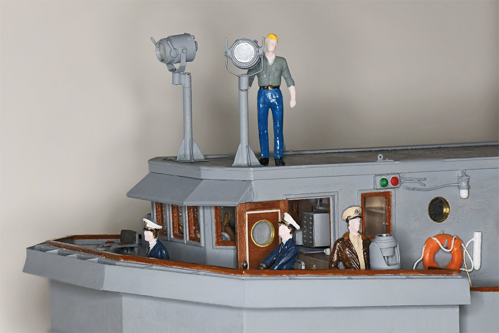
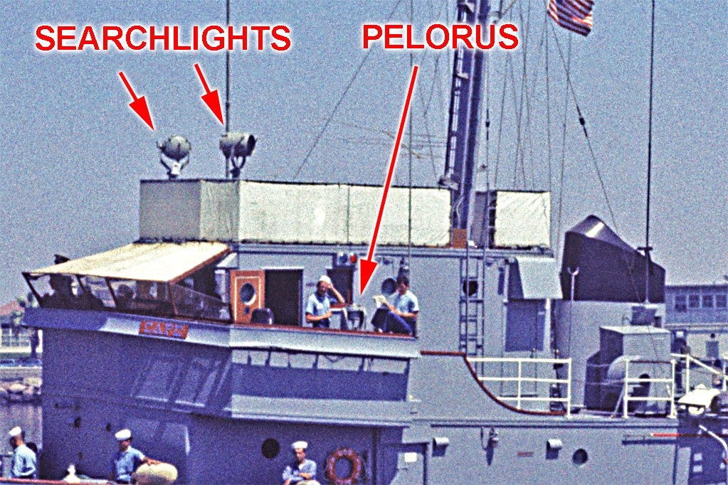
SEARCHLIGHTS One of the challenging things about modeling ships is trying to keep up with changes that were introduced over the life of the vessel. There were a lot of changes on the Cape over the years. The position of the searchlights was one of those changes. When the ship was commissioned in 1959 (left above) the searchlights were mounted on the open wings of the bridge. But by 1969 (right above) the searchlights had been moved to the O2 level above the pilot house. This freed up room on the bridge wing and placed the searchlights higher where they would be more effective. You can see a lot of other changes that had occurred during the 10 year period when the Cape was in service. The Cape had a number of modifications that never made it to the USS Cove MSI-1. The searchlights were never moved to the O2 level on the Cove. Notice that the vertical ladder from O1 to O2 level was moved aft on the Cape, and the life rails on the O2 level were different than on the Cove. The whistle was moved from the O2 level directly over the open bridge (where it would have been annoyingly loud) to a higher position on the mast. A voice tube was added on the O2 level to communicate with the helm. This is a kit of parts for one 1:48 scale 12 inch (305 mm) searchlight, flanked by pieces of another assembled unit. The hardest part of the assembly was the base, where soldering each of the four support pieces to the tube and base plate risked unsoldering all the rest. The largest brass tube is 5/16 inch (7.9 mm) OD and the third (inner) tube is 1/4 inch (6.4 mm) OD, or 12 inches at 1:48 scale. Most of the flat parts are 0.005 inch (0.13 mm) brass sheet, but the yoke was made from 0.010 inch (0.25 mm) brass. Most of it is soldered together, but I did use CA gel in a couple of places. The shutter assembly (lower center) was a bit tricky. Six narrow strips of 0.005 inch brass were overlapped and soldered to the back of a thin ring cut from a 7/32 inch (5.6 mm) tube. Here are some photos of the complete assembly. After it is painted I will put a circle of clear styrene in front of the shutters. The parts rotate around the offset vertical mount in two places, and the light rotates around the horizontal axis. The assembly is 1.375 inches (35 mm) high, or 5' 6" (1.7 meters) high in 1:1 scale.

- 492 replies
-
- 13
-
-

-
- minesweeper
- Cape
- (and 1 more)
-
Thanks everyone! I am working on the searchlights for the O2 level - photos soon.
- 492 replies
-
- 5
-
-
- minesweeper
- Cape
- (and 1 more)
-
There are MANY versions of the DXF file format. Different programs use different versions, and many are not back compatible to older versions. Sometimes companies would introduce a new version that was deliberately incompatible with other software, to prevent users from switching to the other programs and taking their work with them. I haven't used DXF format for many years, but way back when version 13 was the most commonly used version, even after several newer backward incompatible versions were introduced.
-
It is a beautiful ship. Enjoy the build!
-
Brad, Thanks. If you look closely at the blueprint drawing for the grenade locker you will see that the heat shields actually had chamfered edges, about half an inch (12 mm) angled 45 degrees from the larger surface. At 1:48 scale that comes out to about 0.010 inch (0.26 mm) wide chamfers. I have a photo etch metal bender and tried to make the bend in some 0.003 inch (0.08 mm) brass, but it wouldn't grip the metal tight enough and it kept slipping out of the bender. So we will just have to imagine the chamfer. In hind sight I should have used 0.010 inch (0.25 mm) brass for the shields, and then I could have filed the chamfer on the edges. Maybe next time!
- 492 replies
-
- 3
-
-
- minesweeper
- Cape
- (and 1 more)
-
I tried to solder the heat shields to the outside of the grenade locker instead of using CA. But it is so small that as fast as I soldered one piece another became unsoldered, especially on the tiny fuse lockers. There isn't any way to attach enough heat sinks!
- 492 replies
-
- 3
-
-
- minesweeper
- Cape
- (and 1 more)
-
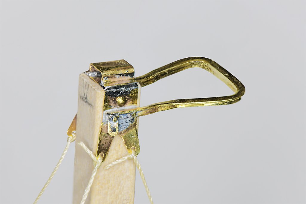
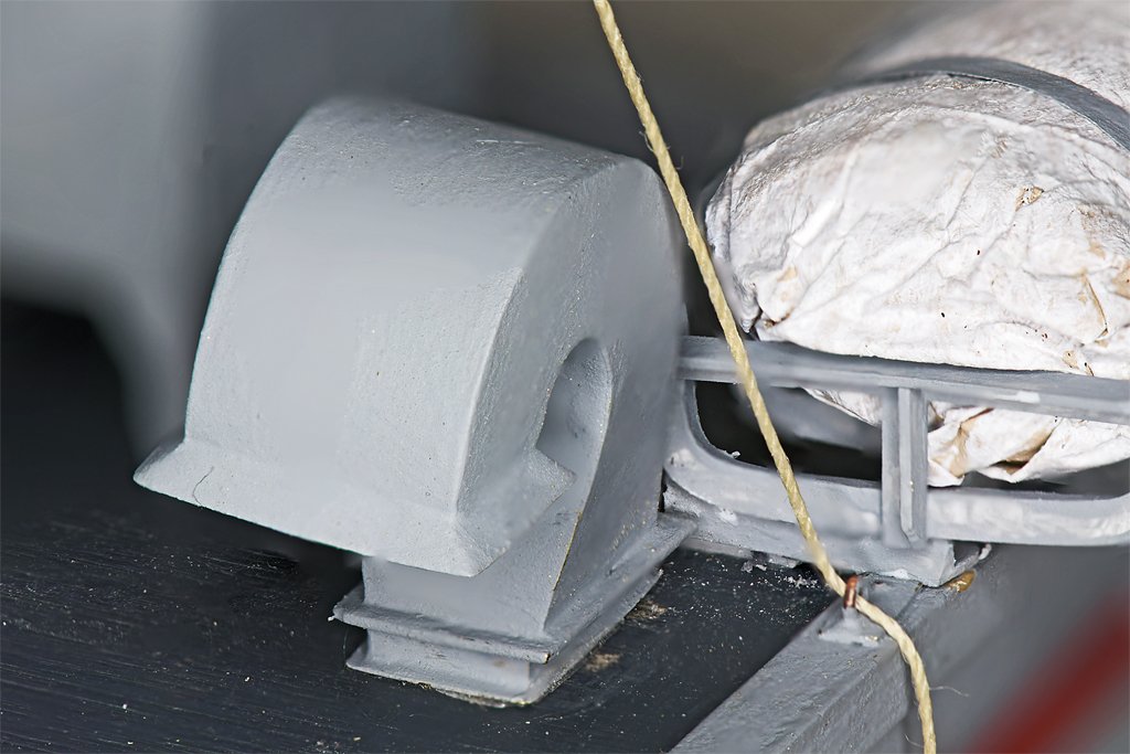
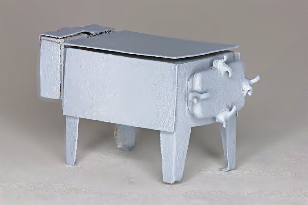
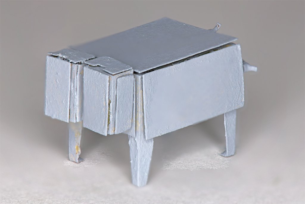
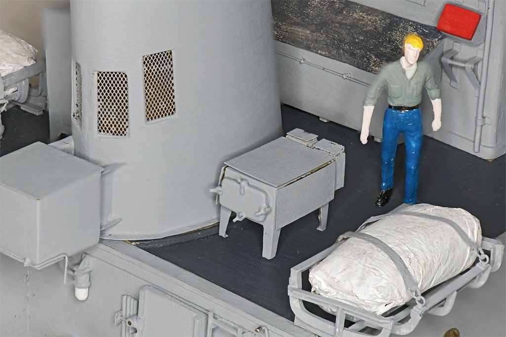
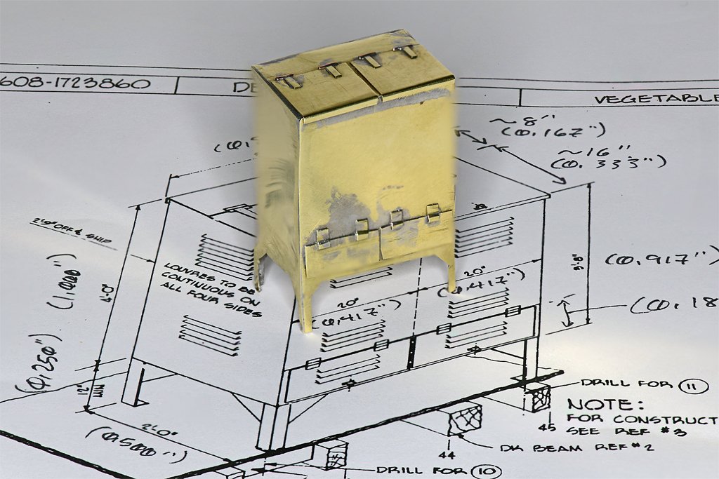
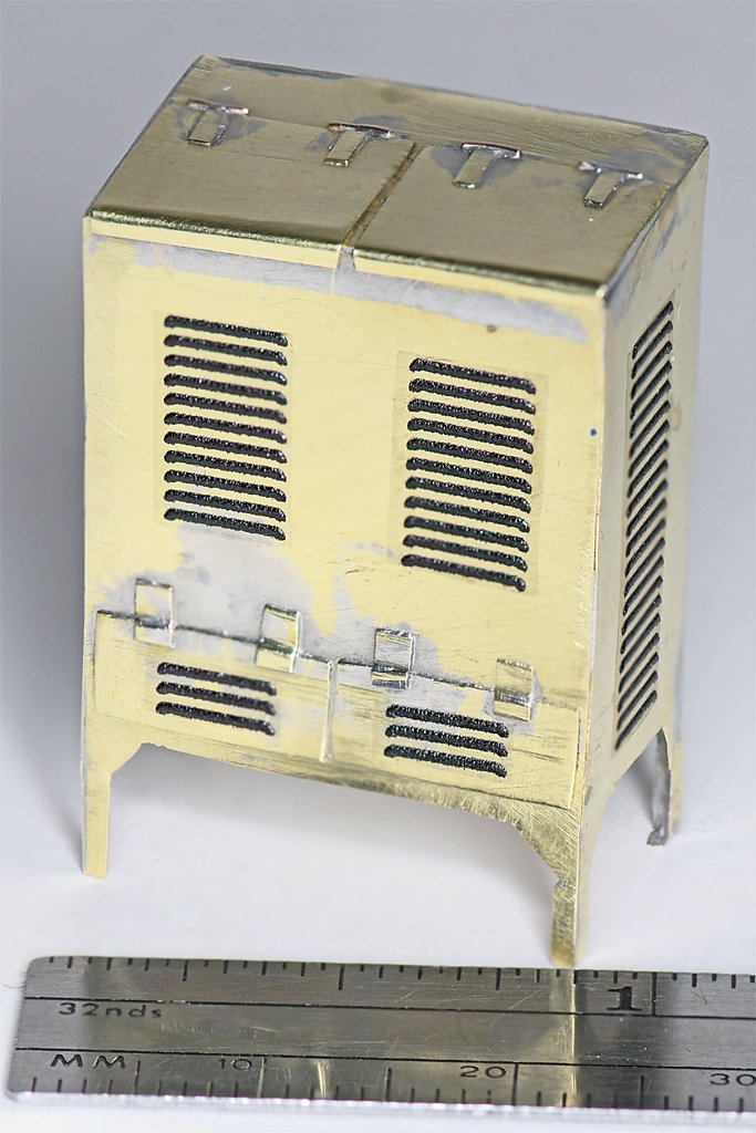
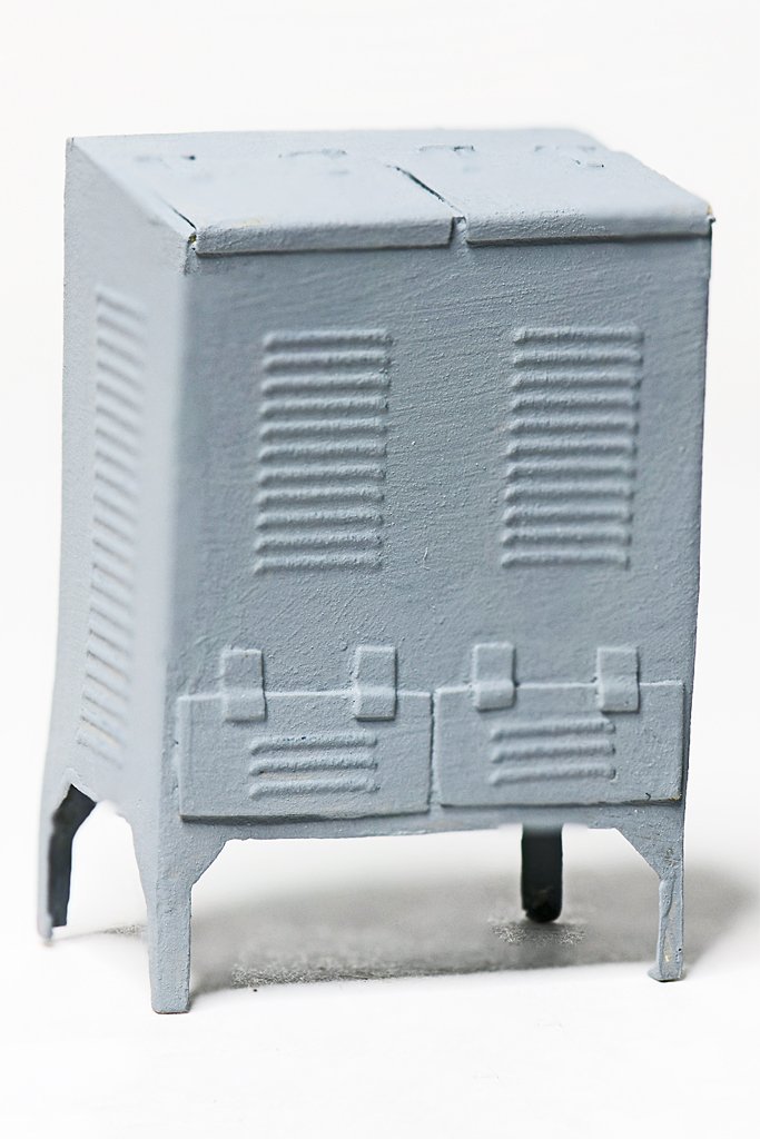
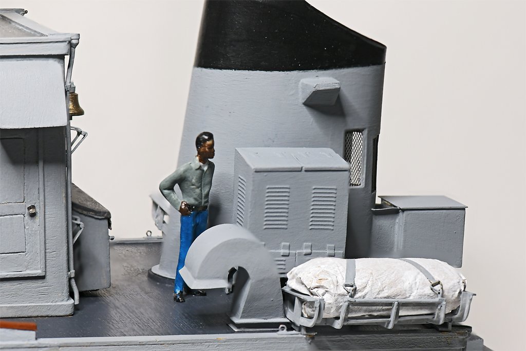
We spent a few days on the Oregon coast. We had sunny days, temperatures in the low 60s F (~18 C), no wind, flat calm seas and low tides! At the 45th parallel in the middle of winter!! It was some of the best winter days I have seen on the coast in 50 years! We had a great time walking, exploring tide pools, picnicking and just being lazy! I have done a little more on the model bit by bit. First up, the vegetable locker (also called the potato locker). I am getting better at working with brass, but sometimes things don't cooperate. The big solder smudge came from the inboard hinge on the left door. It moved when I was soldering it in place (it is tiny and hard to hold). And again, again, again ... You can see where it strayed before I finally fixed it in place! Total height of the locker is 1.25 inches (32 mm) and 0.85 inch (22 mm) wide. It was made from 0.005 inch (0.13 mm) thick brass sheet. As you can see from the blueprint drawing it had lots of louvers (my photos show even more). I considered several ways to create these, but I just don't have the machine shop tools to make dies for stamping them. Then I remembered Archer Fine Transfer 3D rivet decals, and wondered of they also made louver decals. They do!! I ordered their assorted louver sheet # AR88055 and followed their instructions to the letter. They worked perfectly. There is no visible edge to the decal material! The only caveat/complaint I can think of is that the louvers aren't quite high enough. With strong lighting from above, as in these photos, they are visible. With ordinary room lighting they cannot be seen from a distance. But they certainly are an easy way to add louvers to potato lockers and other equipment! Here you see the most important man on the ship - Petty Officer Johnson - standing beside the vegetable locker. Of course the Captain is supposed to be the most important person, but Johnson was the cook. And if you want a happy crew you need to feed them well. Johnson was a great cook, so we had a small and happy crew. The grenade locker was a bit smaller and more detailed. The larger locker contained one box of 50 MK3A1 concussion grenades. The two smaller lockers attached to the rear each held a box of 25 M206A1 grenade fuses. While I was aboard we never used a grenade. I probably didn't even know what was in the locker. Maybe nothing. The main box is 0.448"W x 0.276"H x 0.625"D (11.4 x 7 x 16 mm). This piece had the cleanest and sharpest soldered edges of anything that I have made. They looked really good. But then I had to add the sun shield plates that were attached one inch (25.4 mm) outside all the surfaces, and they hide the nice metalwork. The shields kept hot sunlight off the locker, with space between the shield and locker for heat to be carried away by the breeze or convection. Wouldn't want to cook off the grenades! The shields are glued on with CA gel. It is brittle, and the shields keep breaking off when I handle the piece. The grenade locker is shown in this position in the blueprints, on the starboard side of the smoke stack. But I have one photo I took on the Cape that shows it oriented differently. I may position it as shown in my photo. The blueprints also show a pyrotechnic locker just forward of the life raft, but my photos reveal that it wasn't there in 1969 (the year I am modeling the ship). I have no idea where it was (if it was still on the ship) so I do not plan to model it. This completes the deck furniture on the O1 level. Now I need to add the life rails and life lines. These will be somewhat fragile, so I may wait until all the details are added to the O1 deck house (pilot house) on the O2 level and the O1 deck house is fastened permanently to the main deck house.
- 492 replies
-
- 14
-
-
-
- minesweeper
- Cape
- (and 1 more)
-
Sails on a British Cruizer Class Brig
Dr PR replied to DennisL's topic in - Build logs for subjects built 1801 - 1850
Even on many larger ships like clippers the royals were just "temporary" sails. The sails were rigged to the yards on deck and then the whole rig was hoisted. They had a halliard for raising the yard and no lifts or sheets. The clews of the sails were just tied to the topgallant yard arms and the topgallant braces controlled both sails. -
Good progress! The truss tackles were a bit tricky for me. They work like yard lifts if you pull them too tight, but don't hold the yard if they are too loose. The yard didn't end up exactly where I wanted it, but it was OK.
-
And standing up there you would have to watch out for the boom swinging when changing course! If it was me I would stand on the deck behind the deck house. I guess you could pull the tiller with the rope.
-
The end of the tiller is over the cabin roof. Where did the helmsman stand?
-
Here is an update on the 8" shear/brake. I have been using it for six months now, and have a few comments about its usefulness. It is in no way a "precision" tool! Shear 1. As noted above, the stop cannot be positioned closer than about half an inch (12,5 mm) from the cutting edge. If you want to cut narrower strips you have to just take your luck at cutting with any precision. I have been eyeballing it by marking the cut line on the metal (thin brass) and trying to look straight down the cutting surface to align the line with the cutter. Then I hope the metal doesn't move while I am rotating the handle to lower the cutter. 2. The machine does not have any type of restraints for the metal being cut. You cannot position it accurately and then clamp it down so it cannot move. This is a BIG shortcoming! Larger machines always have a clamp of some sort that holds the metal before the cut starts. This prevents the metal from rotating around the cutting edge during the cut. The amount of rotation with this type cutter is very small as opposed to what happens with scissors type cutters (sheet metal shears), but there still can be a small amount of rotation. 3. You should feed the metal from the back side through the gap between the cutting bars. I have tried feeding from the front, but very narrow strips sometimes fall into the gap below the cutters and disappear into the machine. With thin metal (0.005 inch, 0.13 mm or thinner) is fed from the front the machine doesn't always cut, but may fold the material down between the cutters. I have tried to adjust it so this doesn't happen, but it is hit or miss. **** The combination of these shortcomings makes it almost impossible to cut strips narrower than 1/2 inch (12.5 mm) accurately. I tried to cut some strips of 0.005 inch brass 1/4 inch (6.35 mm) wide and had to repeat the effort seven times before I got a strip close to the right width with parallel edges. In most cases the cut started the correct thickness but the metal moved during the cut so at the end of the cut the strip was significantly (0.010 to 0.030 inch, 0.5 to 0.7 mm) wider or narrower. I tried to cut some 1/16 inch/1.6 mm wide strips and that failed every time, varying from half to double the desired width. None had parallel edges. For me this is a real problem because I need to make a lot of narrow strips of thin metals (I can find nowhere to buy such strips). I think a laser cutter may be the only machine suitable for this. ***** 4. When you feed the metal from the rear it passes under the wide bar over the top of the machine about 1.25 inch/32 mm from the cutting edge. You always have about 1.5 inch/37 mm "waste" on each sheet that you can't cut reliably with this machine. 5. There is no mechanism for positioning the stop accurately if you are cutting pieces more than 1/2 inch/12.5 mm wide. There is no way to position the face of the stop parallel to the cutting edge accurately. The stop slides over two bars projecting from the front of the machine with a very loose fit. So the face of the stop can rotate with respect to the cutting edge. When you think you have it in the correct position and tighten the first screw to hold one end in place the stop moves/rotates so the face is no longer in the correct position/distance. Worse still, when you tighten the second screw the stop moves/rotates again so the face of the stop is not parallel to the cutting edge. You will need to try and try again, carefully measuring the distance from the ends of the stop to the cutting edge to finally get the stop positioned correctly for a cut parallel to the face of the stop. Then, if you are cutting thin metal, the edge of the metal that is supposed to be touching the stop can slip under the lower edge of the stop, allowing the metal to rotate during the cut, producing non-parallel edges! The stop is almost useless. **** The cutter has some serious limitations for working with narrow strips of thin material. But it is not useless! With patience and careful positioning, holding the material down with my fingers, I have succeeded in cutting many pieces correctly - but also producing a lot of waste material. Brake I haven't used the brake (bending tool) except to test that it will bend metal. You really can't use it for any angles less than about 1/4 inch/5 mm wide because the lower "prism" V notch has edges about that long, as do the upper bending tools. There is no way to position the metal accurately relative to the bending edge. Again, there is a stop on the back of the machine, but it has the same "slop" in positioning as the shear stop. And this stop can be positioned no closer to the bending edge than about 1/4 inch/5 mm. So the brake can be used for bends with edges about 1/4 inch wide and larger, but it is essentially useless for smaller bends. But for making small metal boxes or chassis it could be very useful.
-
Beautiful model!
-
Eberhard, Good catch! The plastic for the cradles is Evergreen Scale Models styrene! Duh!! I have corrected the original post. I have worked quite a bit with acrylic (Plexiglas) and you are right - it doesn't respond well to cold bending. I should get a hot air heat (soldering) gun. We used them at work for soldering very high density leads on ICs. They had a small diameter (1/4 inch, 5 mm) removable nozzle that would have been perfect for heating the styrene angles while bending them. And it would be handy for preheating metals for soldering.
- 492 replies
-
- 4
-
-
- minesweeper
- Cape
- (and 1 more)
-
I am working to finish up the "furniture" on the O1 level. First up was a supply vent that provided fresh air to the engine rooms. I wanted to make it from 0.005 inch (0.13 mm) brass because it looked like it would be fun. I made a 3D CAD model based upon the blueprints, and from that generated the 2D surfaces. These were printed and the parts cut out to serve as templates. They were glued (glue stick) to the brass sheet and then the parts were cut out with scissors - like cutting out paper dolls! The pieces were soldered together with the same technique used on the smoke stack. It is sitting on a US one cent piece in the right hand photo. It went together pretty good. I drilled a hole in the center of the base and soldered in a short 1/16 inch (1.6 mm) brass rod to serve as an alignment pin. One of the "fun" things about it is that it has a rectangular duct opening, with the long axis running athwartships (port to starboard). But the long axis of the duct penetrating the deck runs fore-and-aft. So I had to make a 90 degree twist without reducing the cross section area of the duct. This is simple - if you have ever worked with HVAC ducts, and you have an entire workshop full of sheet metal bending tools. But it wasn't too difficult at 1:48 scale, except I had to repeat one solder joint seven times before I got everything lined up perfectly. Murphy was having fun that day! I placed the mounting hole in the deck where the blueprints showed it. This was a bit critical because a life raft was stowed immediately between the vent and the aft end of the deck house with not a lot of spare room. And I had not yet made the life rafts! That was the next project. I wanted to make the life raft cradle from brass. But the frame was made of 1/16 x 1/16 inch (1.6 x 1.6 mm) "L" extrusions, with a bend radius of only 0.125 inch (3.1 mm). That is only twice the width of the pieces, and there was no way I could bend the small brass pieces without breaking the part on the outside of the curve. I also have some 1/16 inch styrene "L" angle stock. I tried bending it cold and it worked! But it didn't hold the shape and sprang back at least half the angle. I cut out a wooden form and clamped pieces in place in the form. Then I used a hair dryer to heat the plastic. When it cooled it was almost shaped correctly. I put the pieces back in the form and held a hot soldering iron very close to the bends. After a few seconds I briefly tapped the bend a couple of times (the plastic did melt slightly on a couple of pieces). Then when I took the pieces out of the form they held their shape. The parts were clamped together one by one and glued using styrene solvent (methylene chloride and trichloroethylene). Nasty stuff - you should have good ventilation if you don't want to lose a few brain cells. The cradles came out OK, but not perfect! For the life rafts I cut a narrow strip from an old cotton T shirt . It was rolled up and glued together, and the loose ends were cut off to shape it better. Then it was rolled up in some silkspan sail material left over from my topsail schooner build. This was glued around the cotton and then painted white. This was one of the minor differences between the Cape and the Cove. The life raft covers were painted deck gray on the Cove. I have noticed several trivial differences like this between the sister ships. The paint on the life rings is another example. It seems that if the Cove painted things one way the crew of the Cape painted them differently. The rafts were strapped into the cradles with silkspan straps that had triangular metal fittings (0.013 inch/0.33 mm brass wire) at the ends. On the outboard side of the cradle these fittings passed through eyebolts on the cradle. On the inboard side the triangular fittings were lashed to a ring on a hydrostatic release. The base of the release was bolted to the deck. The dome shaped bit was the pressure release. If the ship sank water pressure would cause the ring to separate from the release, allowing the straps to swing back and release the life raft. At the same time another hydrostatic mechanism in the raft would start it inflating. Here you can see the two rafts in position on the O1 deck. Three deck lockers will finish out the O1 deck furniture and then I can start on the life rails and life lines. However, all this work on fiddly bits had been straining my left hand, causing some pain in tendons in my left thumb. Bummer! I can only work a couple hours at a time before the thumb cramps and the tendon becomes painful. Murphy has started a different tactic to screw up this build. I have orders from the Admiral to cut back on my modeling time and give my hand a rest. Actually I think she is miffed because she thinks I am spending more time with the model than with her! So I think we will take a vacation (the weather looks nice on the coast next week).


- 492 replies
-
- 16
-
-
-
- minesweeper
- Cape
- (and 1 more)
-
splice hull plank.
Dr PR replied to Janne's topic in Building, Framing, Planking and plating a ships hull and deck
Janne, Planks were always shorter then the actual hull length except for very small boats. So it was necessary to use several planks along each strake (a line of planks is a strake). For fairly regular surfaces like decks, planks were laid in a repeating pattern. The ends of the planks were fastened down over deck support beams so the fasteners would have something to fit into. Two planks came together at these butt joints. The planks were laid with several unbroken planks in between each butt join. Where two planks met end to end there would be some number of unbroken planks laid side by side before the next place where two planks met end to end. If there were two unbroken planks between the pattern was called 1 in 3 (one joint and two unbroken planks). It would look something like this where "---" is the plank and "-|-" is the butt joint: ----------|-------------------------------|-------------------------------|-------------------------------|------------------ ---------------------|-------------------------------|-------------------------------|-------------------------------|------- --------------------------------|-------------------------------|-------------------------------|---------------------------- ----------|-------------------------------|-------------------------------|-------------------------------|------------------ It could be 1 in 2, 1 in 3, 1 in 4 or whatever. There are some more complex patterns, but they are not as common. Hull planking as similar, but the curvature of the surface often called for "creative" planking that did not follow a 1 in N pattern exactly. However, there was an attempt to stagger the butt joints in a regular pattern with several unbroken planks in between. This increased the strength of the hull. Two butt joints were never placed side by side in adjacent strakes. -
Nice interior detail Craig. Like building a floating doll house. It is fun to add interior detail that will not be seen with a casual look. But peek in at just the right angle and surprise!
-
Yes! And the chem majors' classes were far more demanding than the ordinary chemistry classes - and a lot more fun. Except for the 5 hour organic chemistry labs every Monday, Wednesday and Friday afternoons!! The laboratory had windows, and in the spring we could see the kids playing frisbee on the lawn outside in the warm spring sunshine. That made the labs seem like 10 hours long! Organic chemistry was interesting. Quantitative and qualitative chem were drier and mainly boring. I thought it was physical chemistry that really separated the wheat from the chaff! I switched majors to bacteriology (microbiology) in my Sophomore year and had a much better chemistry background than the other micro students.
- 492 replies
-
- 3
-
-
- minesweeper
- Cape
- (and 1 more)
-
Finish of the Waterway
Dr PR replied to RossR's topic in Building, Framing, Planking and plating a ships hull and deck
I think the answer to the question lies in consideration of how much wear and tear the item will receive. There is a reason decks are not painted - decks get walked on and things dragged on them. Paint would be scratched off constantly, requiring unending repainting. Usually real decks on working ships were not finished. Navies even holystoned decks to grind off the tarnished surfaces. * However, yachts and other vessels that see light service do often have "finished" decks. So will the waterways get the same wear as the deck boards? If so I think they would not be painted. * Note: An exception to this "rule" is that warships generally have large crews, and "idle hands are the Devil's workshop." So some things do get painted or polished just to keep the crew busy.
