
HOLIDAY DONATION DRIVE - SUPPORT MSW - DO YOUR PART TO KEEP THIS GREAT FORUM GOING! (89 donations so far out of 49,000 members - C'mon guys!)
×


Dr PR
-
Posts
2,441 -
Joined
-
Last visited
Content Type
Profiles
Forums
Gallery
Events
Everything posted by Dr PR
-
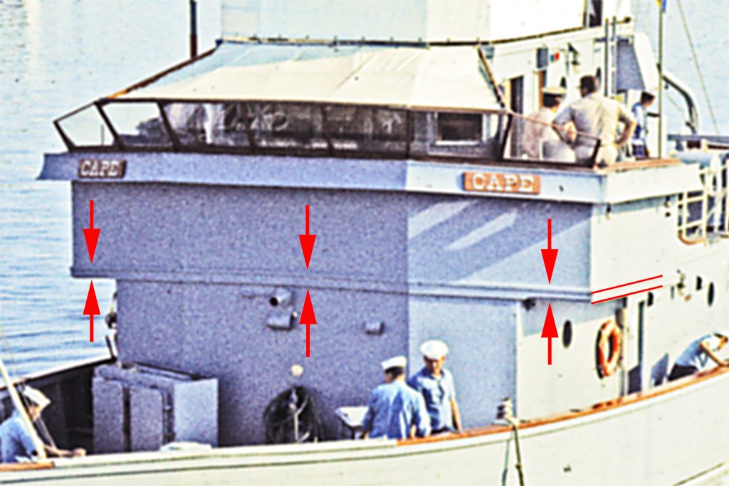
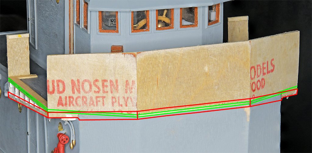
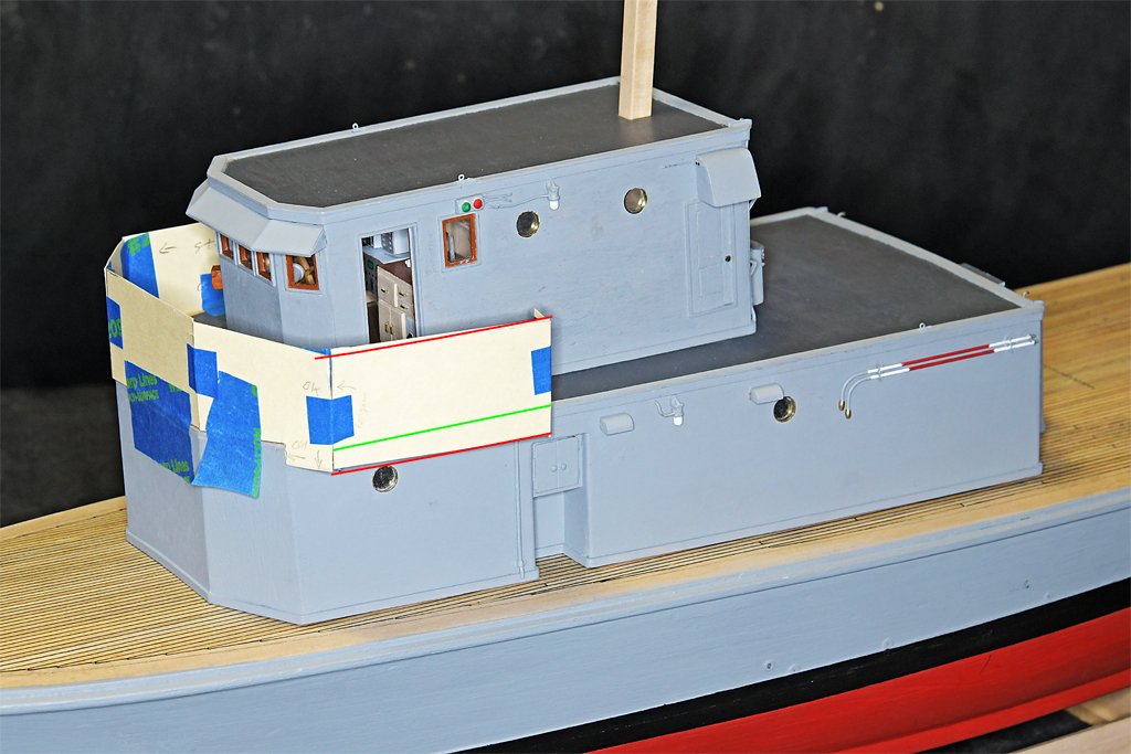
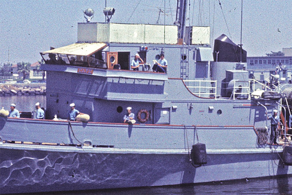
 Thanks again for the comments and likes. More bridge bulwark work. As I was studying photos and blueprints of the Cape and Cove I noticed something that looked peculiar. The trim at the bottom of the bridge bulwark sides is the same width as the trim along the top sides of the deckhouses (red lines). This trim extends across the front of the deckhouse, but it is wider near the center than on the outboard wings. OK, I guessed this was just the designers whim. But I also realized this trim served the purpose of covering the edges of the 3/4 inch (19 mm) bridge deck, just as it covers the edges of the decks on the deckhouses. For the model this is very convenient, because it does the same thing - cover the edges of the 1/16 inch (1.6 mm) plywood I used for the decks. The edges of the decks rest on the deckhouse sides, and it would be difficult to seal and finish the plywood edges as smooth as the deckhouse sides. So the trim hides the model's deck edges, just as it did on the real ships. But why use wider trim at the front? The blueprints say to be sure the trim on the front of the deckhouse covers the edges of the bridge deck. This is where the designer's desire to make a pretty ship - with the bulwark top and bottom following the sheer and camber of the main deck - ran into problems because the bridge deck was horizontal with no camber or sheer. And that was an even greater problem on the model with the thick plywood deck! The green lines in the photo show the outlines of the bridge deck. The red lines show the trim. The trim starts out below the deck edges on the outboard wings and curves up over the deck edge at the center. The normal trim width used on the sides was not tall enough to cover the deck edge at the center because of the camber. So they just made the trim wider across the front. I have painted most of the bulwarks inside and out However I have left a strip at the outside top bare for now. The bridge venturis will mount there (you can see them in the photo of the ship above). They are a bit complicated and will be a project in themselves. A cap rail will fit on top of the bulwarks, and that complicated set of windows and awning supports will fit onto that. That will be delicate work and I will probably save that for the last work on the deckhouses. I have given up on using real mahogany for the cap rail for the bridge and bow bulwarks. I will use boxwood or basswood and paint them with the same "mahogany" paint I used for the bridge windows.
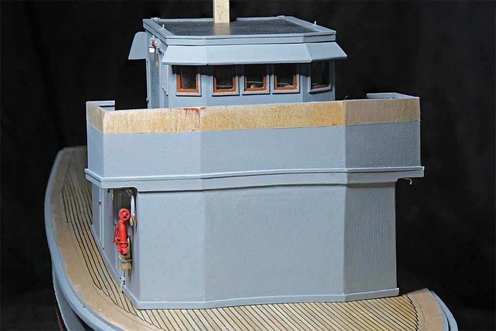
- 464 replies
-
- 9
-

-

-
- minesweeper
- Cape
- (and 1 more)
-
Before you add the deck I recommend sealing the interior of the hull planking with thin epoxy paint or the epoxy used for counter tops. This will seal cracks between planks and glue everything together solidly. My early (1960-70s) planked hulls developed severe cracks between planks after a few years. Wood expands and contracts with humidity changes and causes the cracks to appear. Since I started sealing the interior with epoxy I have had no cracks appear on hulls 40+ years old.
- 48 replies
-
- 2
-
-
- Northwest passage
- Norway.
- (and 2 more)
-
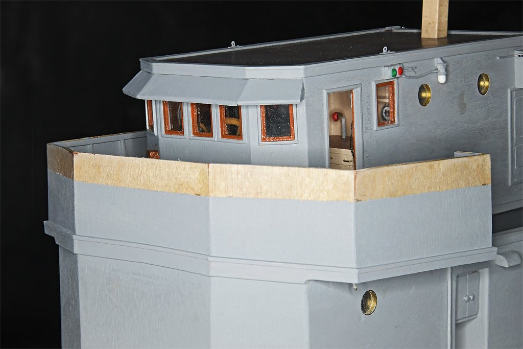
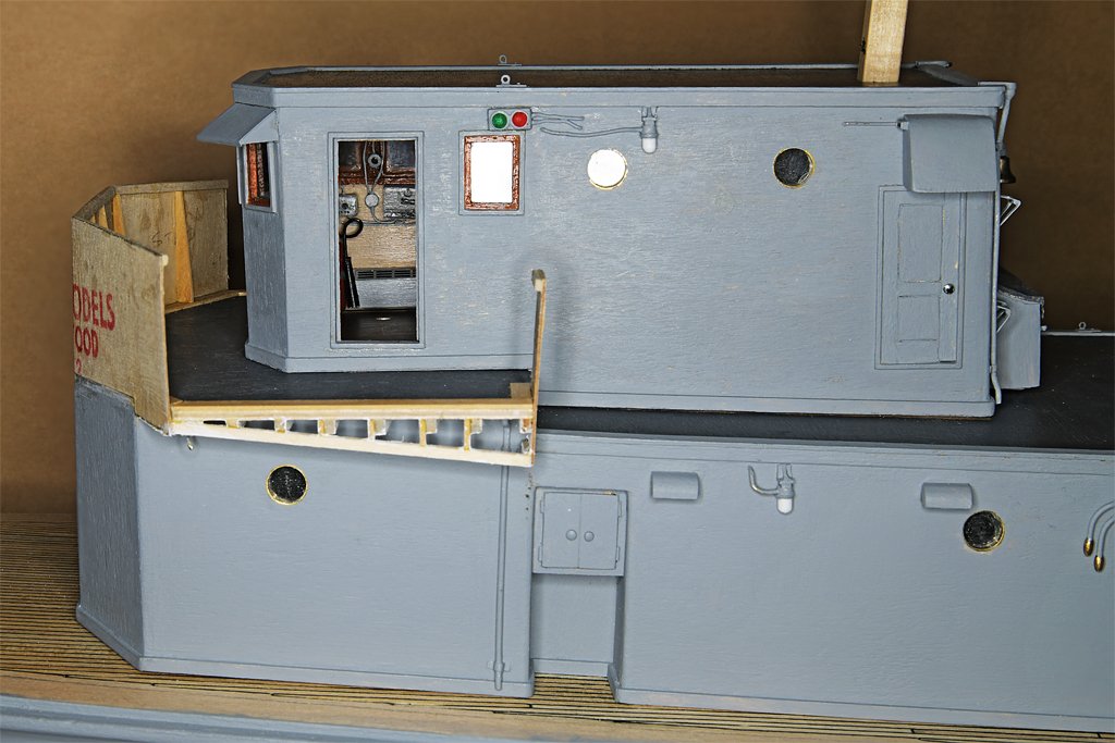
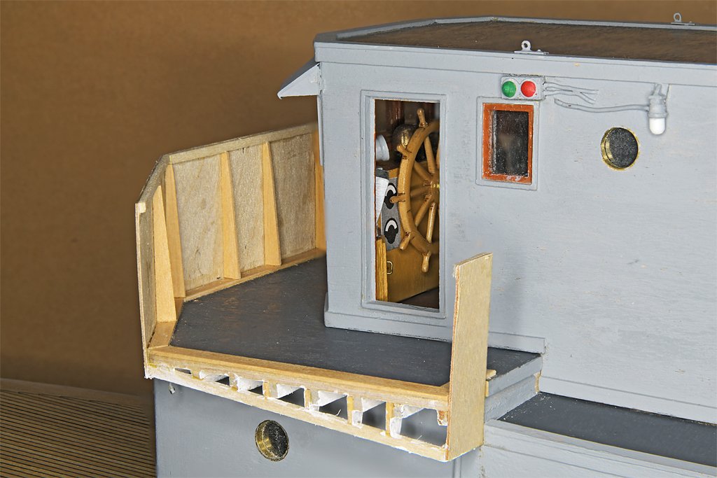
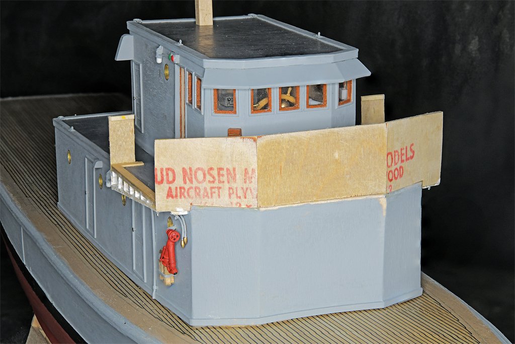
Progress: I have replaced the card templates with actual bulwarks. Mostly. The real ship has 3/4 inch (19 mm) plywood deckhouse and bulwark walls. I am using 1/64 inch (0.4 mm) plywood, and that happens to be the exact scale thickness at 1:48! I thought it might be a bit flimsy but it is actually pretty sturdy. The sill at the bottom is 1/8 x 1/32 inch (3.2 x 0.8 mm) and the "clamp" at the top is 1/16 x 1/32 inch (1.6 x 0.8 mm). The vertical stiffeners are 1/32 inch basswood tapered from 1/8 at the bottom to 1/32 inch at the top. A mahogany cap rail fits across the top over the clamp. I have a sheet of 1/16 inch (1.6 mm) thick mahogany and I am thinking about how I can shave off a 1/32 inch (0.8 mm) thick piece from the edge to make the 1/16 x 1/32 inch cap rail. After I attached the front bulwarks to the man deckhouse I measured the distance from the main deck up to the top of the O1 level bulwark. To my surprise the top edge of the bulwarks agreed with the blueprints to within my ability to measure the distance - only a few thousandths of an inch (~0.025 mm) difference, if any! That certainly is the most accurate part of the entire main deckhouse!! The thin plywood is from Bud Nosen Models. I have had this sheet for decades but the company is still in business if you need some thin plywood. The bulwarks have a 1/16 x 1/32 inch stringer along the bottom inside edge where the deck overhangs the deckhouse side. This is supported by pieces attached to the deck beams. I decided to construct all of this detail before the bulwark sides were attached. This way I could have good access to paint all of the pieces white. On US Navy ships all overhanging parts were painted white, including the overhead in interior spaces. None of this will be visible after the bulwark sides are attached but I will have the satisfaction of knowing that I followed the blueprints to provide adequate support for the bulwarks. Tomorrow I will add the side panels on the bulwarks and start adding the details (voice tubes, washdown nozzles, and other bits and pieces) to the open bridge.
- 464 replies
-
- 13
-
-
-
- minesweeper
- Cape
- (and 1 more)
-
I would think about redoing the hull if this is to be a R/C model. Any incorrect curves and such will affect the handling, causing it to turn one way or the other. It really should be as symmetrical as possible along the centerline.
-
jond, I am curious about the tools you are using for soldering the gudgeons. Those look like some pretty heavy duty clamps that are holding the parts. What are they? Photos? Part manufacturer and number?? I see an ordinary soldering iron in the background, but are the clamps part of a resistance soldering tool?
-
Steve, Funny I never noticed that Petersson (page 72 and 73) shows the tackle outboard of the ratlines. I think this is wrong. The tackle can belay to rings on the channels from inboard with no problems. The tackle must hang freely straight down from the top in order to use it to move things on deck. Since the tackle hangs from the single pendant, the whole thing could be pulled around outboard and allowed to hang down on the ratlines. But this would interfere with climbing. Why would you want to do this? For some reason, of all the rigging on my topsail schooner model, it was making the tackles that I enjoyed most. Don't ask me why. By the way, I think Darcy Lever would approve of your tackle pendants!
-
Pitts, Tapering the planks properly and cutting the correct bevel to fit the adjacent planks is the most important part of getting the planking to fit properly. However, as you noted, getting the planks to curve and twist correctly to fit on the bulkheads is the tricky part. I have tried several of the off-boat plank curving ideas mentioned on the Forum, but although they may get the curvature close they all fail to get that twist. I discovered what I think is a MUCH better way to fit planks to the hull. I bend them in place using a small quilting iron. Here are two links that show how this works. https://modelshipworld.com/topic/37060-uss-cape-msi-2-by-dr-pr-148-inshore-minesweeper/?do=findComment&comment=1074225 https://modelshipworld.com/topic/37060-uss-cape-msi-2-by-dr-pr-148-inshore-minesweeper/?do=findComment&comment=1075263 Heat is the thing that softens the wood fibers and allows them to bend. But the water is the means of conveying the heat into the wood. The planking iron boils the water and the steam carries the heat into the wood. I find that two passes of wetting and heating usually make the plank conform to the hull. In some cases three passes are needed (and in really bluff bows you may have to bend the extreme curves in several steps). After bending the planks in situ on the hull they will hold their shape and lay flat against the bulkheads or frames without any glue or fasteners. This makes it easy to check the fit, and make adjustments if necessary. Then you can glue them in place without needing a lot of clamps. Here is a link describing the plank bending tool: https://modelshipworld.com/topic/37597-plank-bending-revisited/?do=findComment&comment=1075866
-
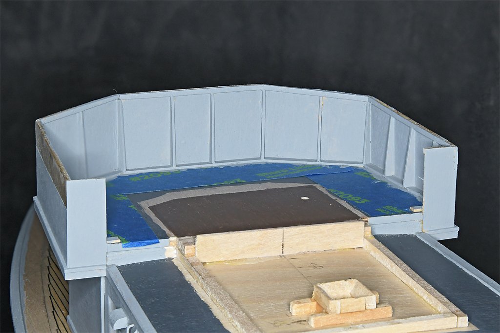
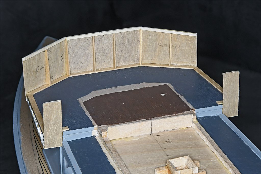
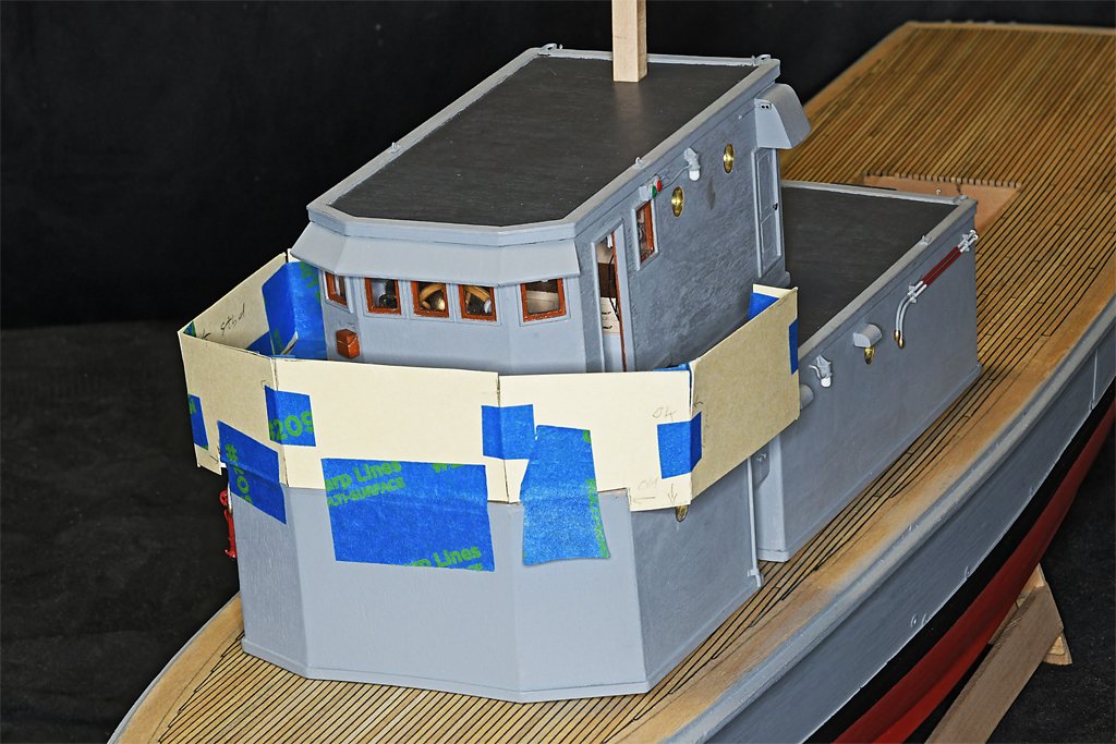
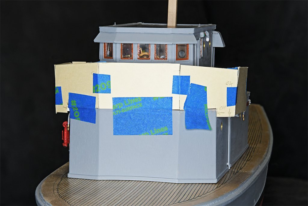
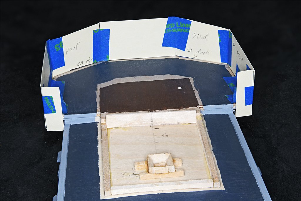
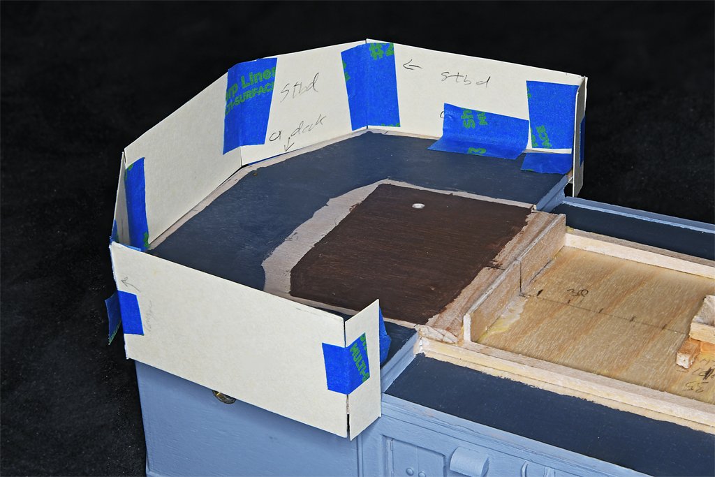
Roel, US Navy ships are a lot like the early Ford Model T cars. Henry Ford said you could have any color you wanted as long as it is black. With Navy ships you get grey, grey or grey. They are not nearly as colorful as your Chaconia! I have started on the bridge bulwarks. This will not be easy! I mentioned in an earlier post that there were no right angles in the main deckhouse. The sides aren't parallel, some of the decks follow the hull's sheer and have camber. The bridge bulwarks sit on that deckhouse and inherit all if it's oddball angles. But a new set of angles are added for the bulwarks. Notice in the photo of the ship the O1 level bulwarks are angled with respect to the top of the pilot house. The bridge deck is parallel to the water (and the pilot house top) and has no camber or sheer. However the blueprints say the top and bottom of the bridge bulwarks must be parallel to both the sheer and the camber of the main deck. This is very obvious in the photo. This means the distance from the bridge deck to the top of the bulwarks is not constant, but varies from point to point! I have modeled the bulwarks in 3D CAD and then printed them in 2D. But these ideal pieces don't fit exactly on the model. My construction of the actual deckhouse had to be repeated several times and the result isn't as precise as the CAD model. Here you can see I am making templates for the sections of the bulwark out of card stock. The green line shows the angle and elevation of the bridge deck. The red lines are parallel to the main deck sheer - looks like I bumped the side piece while setting up for the photos. But you can see how the top and bottom of the bulwark side piece are parallel to the main deck sheer. The aft bottom of the side pieces is at the height of the after part of the O1 level deck (a step below the bridge deck) which has both sheer and camber. Then the pieces angle upward, following the line of the after part of the O1 deck, with the bottom edges converging at the bottom center of the front piece - at least they are supposed to! What is really confounding is that the blueprints do not give any dimensions of the bulwarks except for the height of the front piece above the bridge deck at the centerline, 53.7 inches (1.36 m). Measurements on the drawings indicate the forward and aft ends of the side piece are about 57.5 inches (1.46 m) high. How were the boatyard people supposed to build this thing? Basically all the blueprints tell us is "Here's the general idea fellows, have fun building it." But they did, and now I am trying to use card templates held together with painter's tape to figure out how to fit all of these pieces together. I think this is the third iteration of the card pieces. I get a better fit with each pass - sort of successive approximation. The front center piece is the only part with right angles - it is a true rectangle. The two front side pieces rest on the bridge deck, but are cut to fit down the deckhouse side where the deck overhangs the house sides. These are the really tricky parts. A few more iterations and I should get it right. Here you can also see the mast step on the O1 level. The mast fits into the square pocket at the bottom. The surrounding angled sides are to guide the foot of the mast into place when I am trying to place it blindly through the hole in the O2 level deck.
- 464 replies
-
- 10
-
-
- minesweeper
- Cape
- (and 1 more)
-
True, but the conflicts in this project are really simple compared to trying to figure out the proper belaying arrangement for the full rigging on a sailing ship. That can leave you cross eyed!!
- 464 replies
-
- 4
-

-
- minesweeper
- Cape
- (and 1 more)
-
I came across descriptions of changes the British made to captured American Baltimore clippers - fast topsail schooners. The American rigging was too radical for the Brits - too much sail are. They had a tendency to capsize in strong winds - just blown over before the sails could be reefed. So the British shortened the masts and reduced the sail area. Then the vessels slogged along like all other British vessels of the time, and the faster American schooners ran circles around them. The faster ships could control the engagement - there are some interesting accounts of these actions. After a few of these experiences the Brits began installing taller masts and larger sail areas on their schooners to be able to compete with the American schooners.
-
Here is another photo of boat booms deployed on a mid 20th century ship. https://www.okieboat.com/Copyright images/1 OK City at anchor 1024 C.jpg The booms were hinged to the side of the ship and rested in cradles on the ship's side when not in use. The ropes and ladders were rigged when the booms were deployed.
-
Thanks for the likes and comments. I am deciding what to do next. There are a few small details to add to the front of the main deckhouse, and then what? I want to finish the detailing of the deckhouses before starting on the main deck details. Here are options: 1. Bulwark around the open bridge and bridge equipment details. I want to make the bulwarks before I attach the O1 deckhouse to the main deckhouse. 2. Attach O1 level deckhouse to the main deckhouse. 3. Funnel on aft end of O1 level. 4. Life rails around the O1 level. The bulwark must be finished first, and funnel should be in place. 5. Mast. 6. Construct windows and awning supports on the bulwark. The awning supports can't be placed until the deckhouses are joined. These will be very tricky to make, and delicate. 7. Life rails for the O2 level. Also the searchlights, voice tube and other details. These will be delicate and should go on last. Well, now that I have made the list it looks like the sequence should be as they are numbered! Bulwarks next! But I can also be making many of the detail parts (chairs, peloruses, searchlights, antennas, etc.) that will go on as construction progresses. The mast can be built at any time. It could also be the last piece attached to the deckhouses.
- 464 replies
-
- 4
-
-
- minesweeper
- Cape
- (and 1 more)
-
Be sure the silkspan is very dry before handling it! As I recall, on sailing ships the tablings along the edges of the sail were on the port side, and the larger corner reinforcements and other extra cloths were on the starboard. Will you add boltropes?
-
Boat boom? We used long poles and buoys to mark locations - for mine fields, channels, etc. The spar passed through a hole in the buoy. On the lower end of the spar a cable and weight were attached to anchor the buoy. At the upper end of the spar was a flag (and a radar reflector after radar was invented).
-
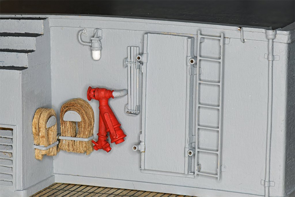
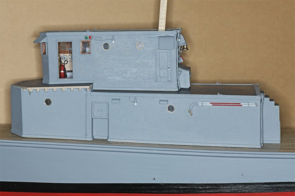
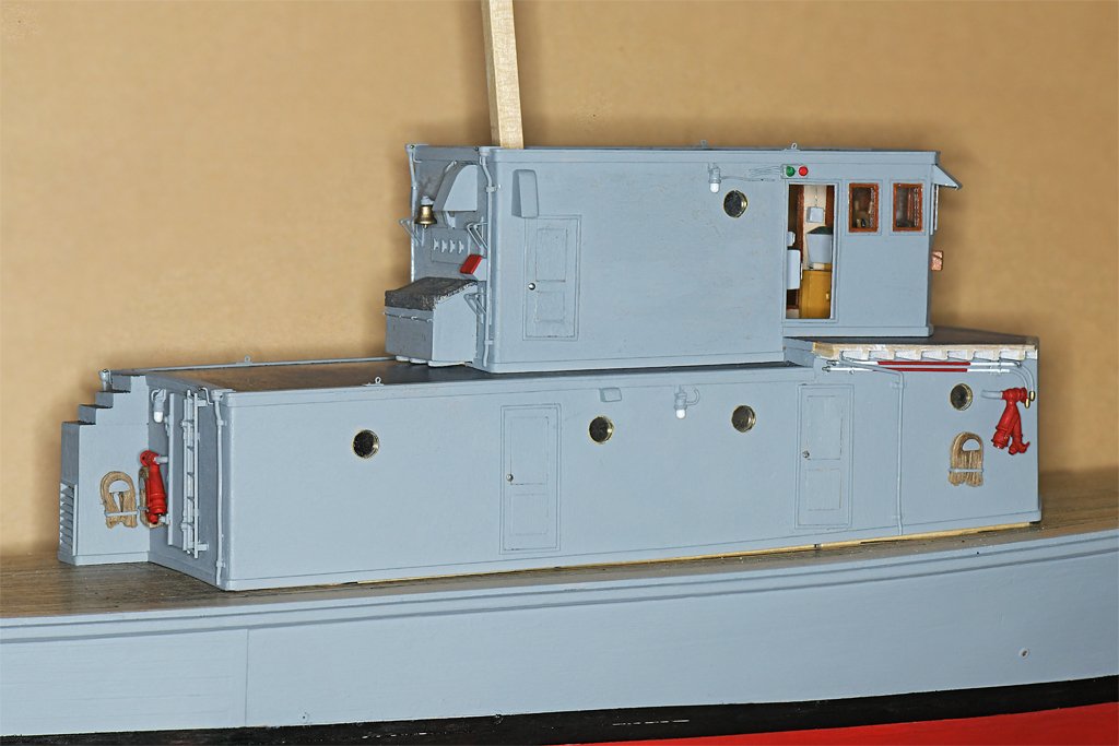
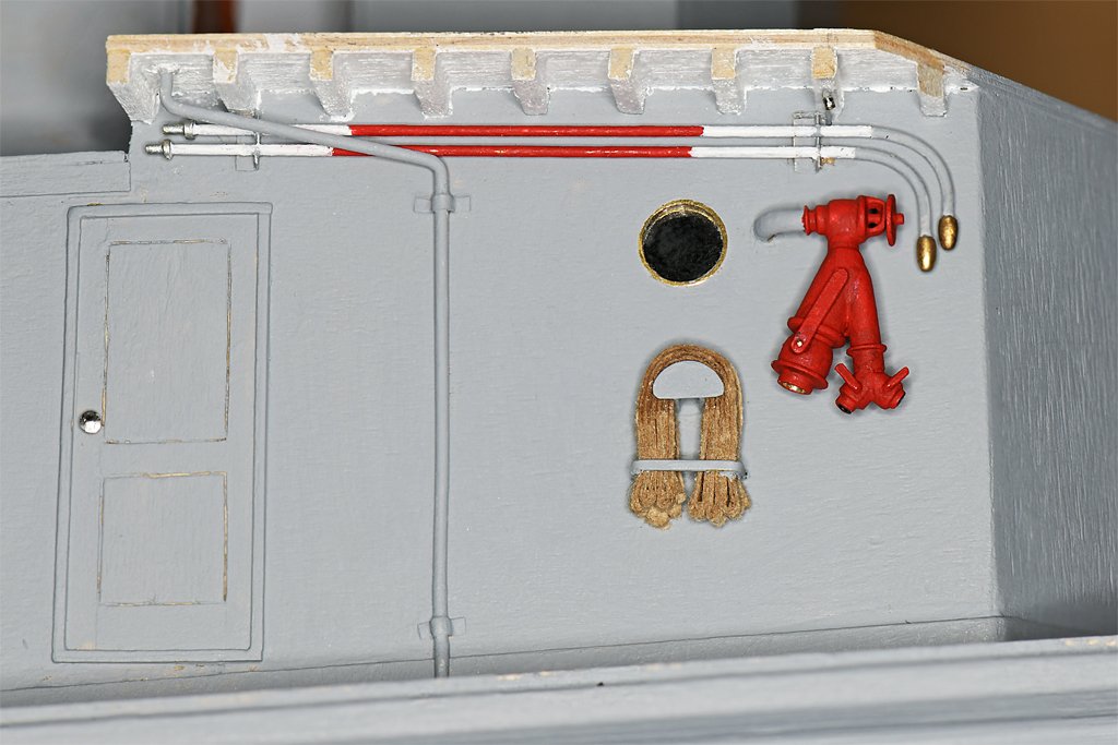
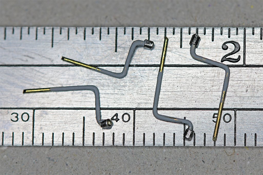
More details. These are probably the smallest details on the model. They are water washdown system spray heads. These are like the common indoor fire suppression system nozzles hanging from ceilings. They should have a base plate with four arms curving up to hold a spray deflection cone. But at less than a millimeter (0.039 inch) long and wide that isn't going to get modeled! The pipe was half inch inside diameter, so it was about 3/4 inch (19 mm) outside diameter. I used 0.015 inch (0.4 mm) brass rod for the 1:48 scale pipe. The nozzles are short pieces of 23 gauge hypodermic needle tubing. Navy ships have washdown sprayers all over the topsides. If the ship is attacked with CBR weapons (chemical, biological or radiological) the washdown system is activated to wash contamination overboard. It would also be used if the ship sailed through fallout from nuclear blasts. You may have seen photos of ships steaming through a local cloud of fog - that would be the washdown spray. I have been installing lots of small details on the deck houses. Lights, ventilation hoods, firefighting equipment and the washdown sprayers. This is the aft end of the main deckhouse. You can see one of the washdown sprayers at the upper right. The ladder is positioned below where there will be a gap in the life rails around the O1 level. To the left of the ladder is where the brow and it's stanchions are stowed. One of the two topside fire fighting stations is here, with the hydrant/strainer, two 2 1/2 inch (63 mm) hoses, and two 1 1/2 inch (38 mm) hoses. Extension pipes with "spud" tip sprayers were mounted on the aft port side of the deck house. The spud tips were a brass ovoid with many small holes. Water sprayed out in a fine sheet of low velocity water fog. This was effective for suppressing flames. Here is the second fire fighting station on the forward side of the main deckhouse. In addition to the hydrant/strainer and two fire hoses, there are two extension pipes with spud tips stowed above. Look closely and you will see another washdown nozzle below the deck beams over the hydrant/strainer.
- 464 replies
-
- 16
-
-
-

-
- minesweeper
- Cape
- (and 1 more)
-
John, It was easy to get the hoses off and on the racks. Because the hose isn't looped around the rack, but is just draped over it, all you needed to do was pull on the hose and it slipped right off the rack without getting tangled. Putting it back on the rack took a bit longer. The "U" shaped bracket that holds the hose below the rack was actually a three piece thing with a hinged bar over the hose and a locking pin on one end. Just pull the pin, swing the bar back out of the way and pull on the hose. The 1:48 scale model bar is 0.030 inch (0/8 mm), but the blueprints call for 0.021 inch (0.05 mm or 1" at 1:1 scale). I wasn't about to try making the hinges and locking pin at that scale. I should say it was usually easy to get the hoses ready for action. But in one firefighting school I had the folks running the class had prepared a damage control locker with a collection of parts where no two pieces would fit together! We had all had other fire fighting schools so on our first drill we went at it with confidence until we couldn't get anything to work. Then frustration turned to laughter when we realized this was a lesson telling us that we needed to be sure all our gear was ready to be used before we really needed it!
- 464 replies
-
- 5
-
-
-
- minesweeper
- Cape
- (and 1 more)
-
Loose Planks
Dr PR replied to Rich Sloop's topic in Building, Framing, Planking and plating a ships hull and deck
Unfortunately, cracks probably will reappear after time. Wood expands and contracts as humidity changes. I have two older (50+ years) hulls that were planked with wood glue between the planks and they have both developed cracks. I started coating the inside of the planking with thin epoxy "paint" that was used to coat motor mounts in flying model airplanes. It prevented fuel from soaking into the wooden mounts. I have also used the thin epoxy that is used to coat counter tops. The epoxy soaks into the planks and bulkheads, and flows between the planks. It glues everything very solid! I have a single layer planked hull that is about 40 years old and it has no cracks. -
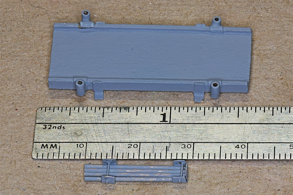
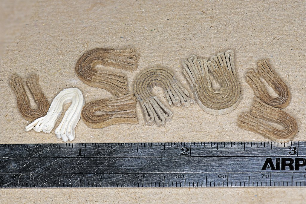
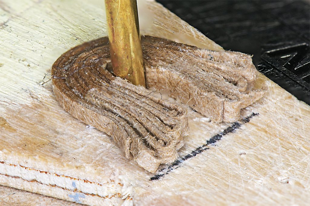
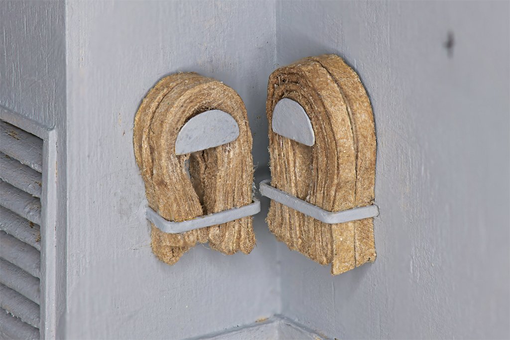
John, Thanks. Here are a few more details. This is my "jig" for making fire hoses, made from a piece of scrap wood. The brass tube is the same diameter as the hose support in the hose racks. The hoses are strips of cardboard about 0.065 inches (1.7 mm) wide. The strips were mostly about 7 inches (178 mm) long, although there were a couple of 11 inch (279 mm) pieces. These represented 25 foot (7.6 m) and 50 foot (15.2 m) hoses. The strips were wound back and forth around the tube. Then they were soaked in white school glue on the top part, leaving the lower "coils" free to hang loose. The glue eventually dried colorless. I experimented with several types and thicknesses of cardboard. The larger hoses here are made of 0.024 inch (0.6 mm) thick card. The others were 0.012 inch ((0.3 mm) card. The thicker material is actually closer to the color of the fire hose (as I recall), but it is a bit too thick. The hoses are too large for the hose racks. The more reddish brown 0.012 inch thick card made better size hoses. The white card made nice assemblies, but even new hoses aren't quite that bright! Here are two hose racks on the aft end of the main deckhouse. Two hoses were stacked on each hose rack. The hoses on the left are 50 foot 1 1/2 inch (38 mm) hoses, and the larger bundles on the right are 25 foot 2 1/2 inch (64 mm) hoses. The hoses should have brass fittings on the ends but I don't know how I would open up the flattened paper strip to represent the round hose at the fitting. For now I am not going to worry about it. The black dot at upper right is where the fire main comes through the bulkhead for one of the hydrant/strainer assemblies. I had to get the hoses installed before I could add other details to the aft end of the deckhouse. This is another detail for the aft end of the main deckhouse. It is the brow (gangway), and it was attached vertically to the bulkhead on the starboard side, inboard of the vertical ladder shown in an earlier post. The brow was 6 feet (1.8 m) long and 2 feet (0.6 m) wide. When used for access to the ship it had four 3 foot (0.9 m) long stanchions with chains stretched between them on the sides of the brow. The thing below the ruler is a holder for the stanchions. It will mount on the bulkhead beside the brow.
- 464 replies
-
- 10
-
-
-
- minesweeper
- Cape
- (and 1 more)
-
I suspect the port lid was pushed open from inside the bulwark and then held open by the lanyard.
-
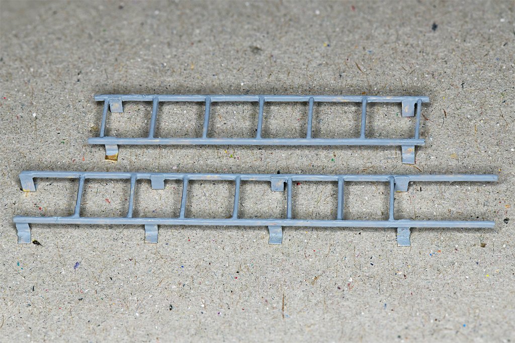
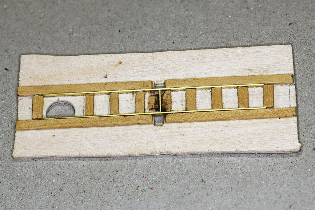
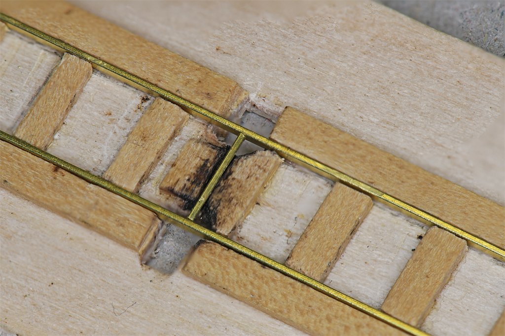
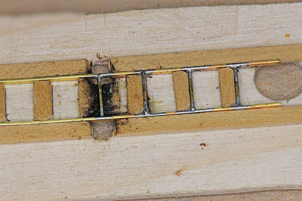
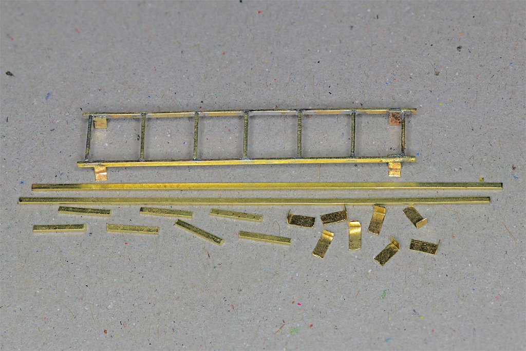
Next up is vertical ladders. I need four for this model. One of the assembled ladders is shown here. It will go on the aft end of the main deckhouse, on the starboard side, from the main deck to the O1 level. Below it are the pieces of a "kit" for a longer ladder that will go on the port side of the O1 level deckhouse from the O1 level to the O2 level on top of the pilot house. The ladder parts were cut from some 0.030 x 0.015 inch (0.76 x 0.38 mm) brass strip made by Special Shapes Company. They made many different small brass shapes, including "U", "H", "L", solid rectangular and round rods. Unfortunately they are no longer in business and I know of no other company that makes these parts. I bought out the stock years ago from a local hardware store that was run out of business by big box hardware stores. I guess there isn't enough profit for the big store paper shufflers to bother stocking these things. The actual cross section dimensions of the side pieces and rungs of vertical ladders in the US Navy were 1 3/4 x 3/4 inch (44 x 19 mm). That would be 0.036 x 0.016 inches (0.9 x 0.4 mm) at 1:48 scale, so the brass strip is just slightly undersize. All of the ladders on the MSIs had rungs spaced 12 inches (305 mm) vertically. This was pretty common in the Navy. However, not all vertical ladders (ladder rungs, steps, etc.) were the spaced the same. When I made the CAD model of CLG-5 the blueprints often showed the spacing of the top rung below the upper deck, and the bottom rung above the lower deck. Then the blueprints said to space N number of rungs equally between the top and bottom rungs. This produced spacings from 11 to 15 inches (279 to 381 mm), although about 13 inches (330 mm) was the most common. The rungs were all 12 inches long (305 mm), although the blueprints show ladders were also built with 18 and 24 inch (457 and 610 mm) widths. I made this jig from scrap wood for assembling the vertical ladders. The 0.094 x 0.030 inch (2.4 x 0.76 mm) side basswood strips are spaced precisely at the outer dimension of the ladder sides 0.28 inches (0.25 + 0.015 + 0.015) or 7.1 mm. At the center are two wooden pieces spaced just over 0.015 inch apart, the narrow width of the ladder rungs. As you can see, the ladder rung is placed in this slot. Holes were cut through the base and wooden side strips to allow a soldering iron tip to contact the brass parts. More basswood pieces were glued to the base spaced exactly 0.25 inch (6.35 mm) from the right hand center piece. Really only three of these spacer pieces are needed to assemble a ladder - the center one and one to either side. But the additional pieces serve to hold the assembly in place and show any spacing errors that might creep in. The gap between these spacer pieces and the outer side pieces is the narrow dimension thickness of the brass strips, 0.015 inch. The brass parts fit tightly between the wooden jig parts. Each ladder rung was soldered on both ends to the side pieces. I placed a small drop of liquid flux in each joint and then touched the tinned tip to the joints briefly. I used a metal tool to hold the rung down until the solder hardened - otherwise it would try to lift out as the soldering iron tip was raised. The photo on the left above shows the correct way to assemble the ladders. First an end rung was soldered between the sides at the proper end position (this varies with each ladder). Then the assembly was lifted and moved so the rung was positioned one step to the right, tightly against the spacer strip. Then the second rung was soldered in place. The assembly was lifted again and moved one place to the right. Another rung was added and so on. It is very important that this sequence is followed to ensure that the spacing of all rungs is equal. Starting at the middle (as shown in the right photo above) or trying to install the end rungs first and fill in the rest later will likely result in uneven spacing. After the ladders were assembled they were cleaned up with files, brushes and sandpaper to remove excess solder. Then the ladder supports were soldered on. These were made from 0.005 inch (0.13 mm) brass strips cut from a large sheet to a scale 3 inch (0.0625 inch or 1.59 mm) width. The faces of the ladders were spaced 6 inches (152 mm) from the bulkhead surfaces. That is 0.125 inch (3.175 mm) at 1:48 scale. The long legs of the supports are 0.125 inch, and the mounting "feet" were 0.0625 inch. Soldering the tiny pieces in place was a test of my patience. A drop of solder was placed on the mounting surface of the supports. I used a resistance soldering "tweezer" tool to pinch the support to the ladder side and then applied a brief current to melt the solder. This worked most of the time but a few of the pieces moved before the solder hardened and I had to remove them and start over. But I finally got them all done. The parts were washed with acetone to remove the solder flux and then painted with acrylic paint. After they are mounted to the deckhouses they will be painted again to touch up thin spots. Before making the two ladders for the ship's mast I will need to replace the two wooden pieces at the center of the jig where the soldering is done. They became charred after repeated soldering. However, most of the black stuff you see in this area is solder flux residue. I had to clean the residue out a few times to be sure the new rung piece fit properly.
- 464 replies
-
- 14
-
-
- minesweeper
- Cape
- (and 1 more)
-
Welcome to the hobby! The problems you are encountering are things we have all been through. What is important is you are learning!
- 19 replies
-
- 1
-
-
- Viking
- Artesania Latina
- (and 1 more)
-
Eberhard, Thanks! But with your watchmaker's tools I think you could have done a much neater job.
- 464 replies
-
- 1
-
-
- minesweeper
- Cape
- (and 1 more)
-
Gaffrig, Thanks for producing the name. I have been trying to remember "breasthook" and it just kept eluding me.
-
I had that problem on my Albatross topsail schooner build. I just ran the gun port lid halliards over the rail and belayed them to cleats in the bulwarks.