HOLIDAY DONATION DRIVE - SUPPORT MSW - DO YOUR PART TO KEEP THIS GREAT FORUM GOING! (83 donations so far out of 49,000 members - C'mon guys!)
×


Dr PR
-
Posts
2,438 -
Joined
-
Last visited
Content Type
Profiles
Forums
Gallery
Events
Everything posted by Dr PR
-
 Harvey, I wish you hadn't told us about the mis-aligned seams! Now we will all be losing sleep worrying about it!
 -
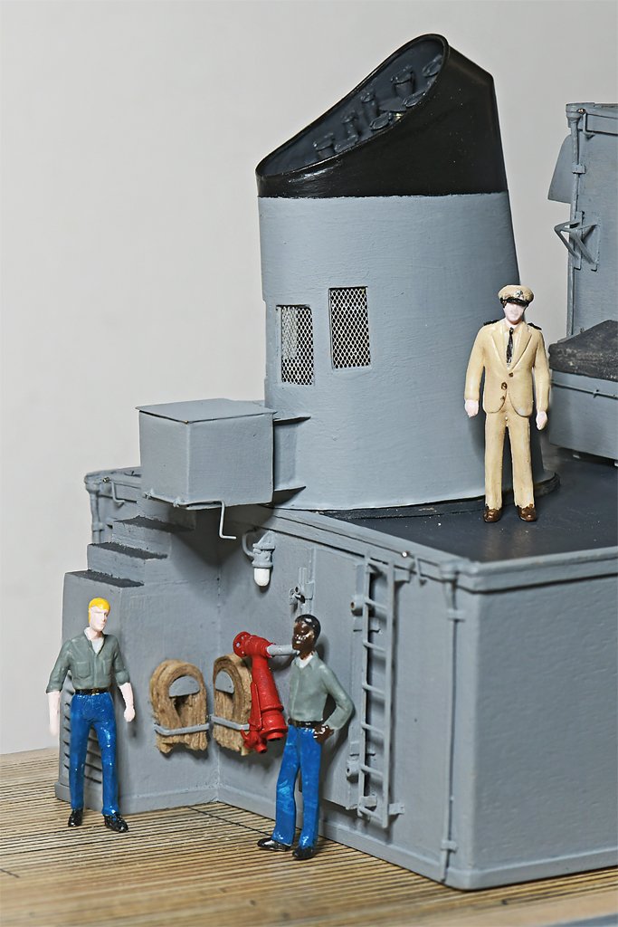
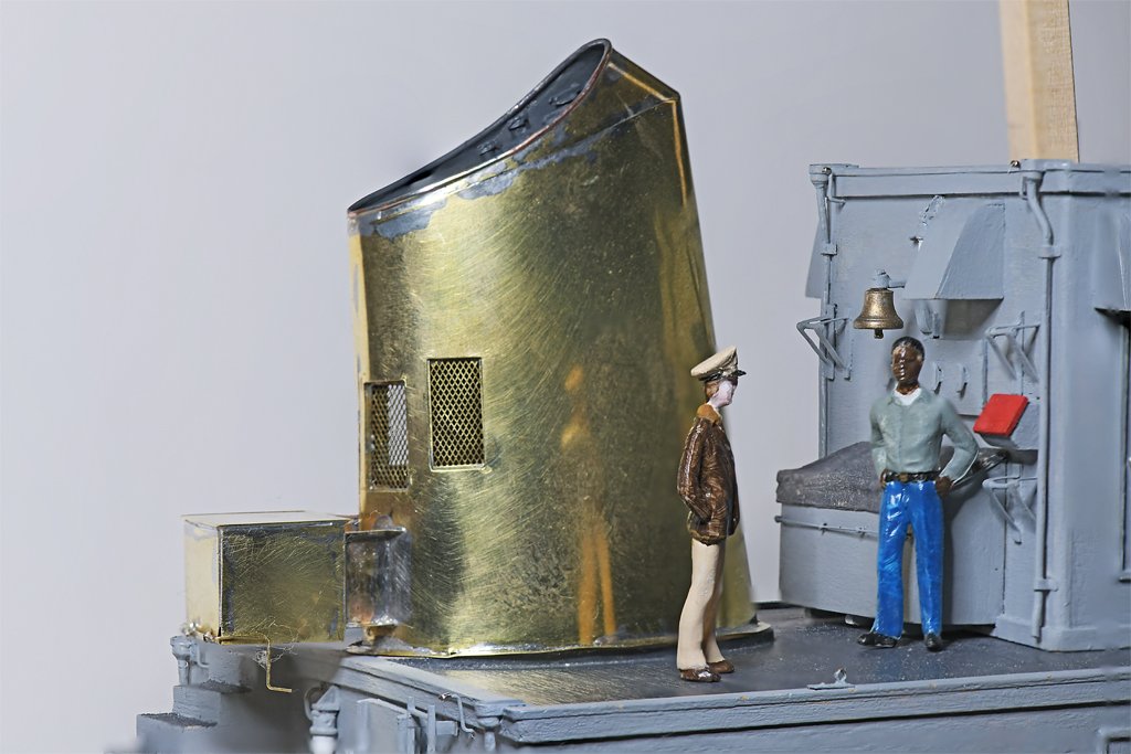
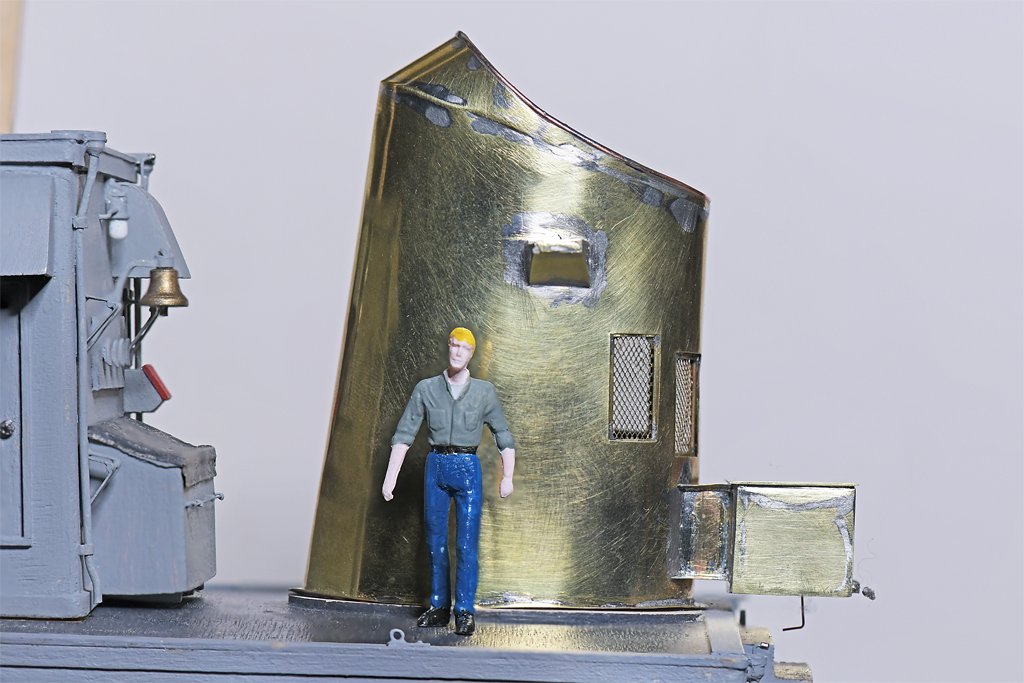
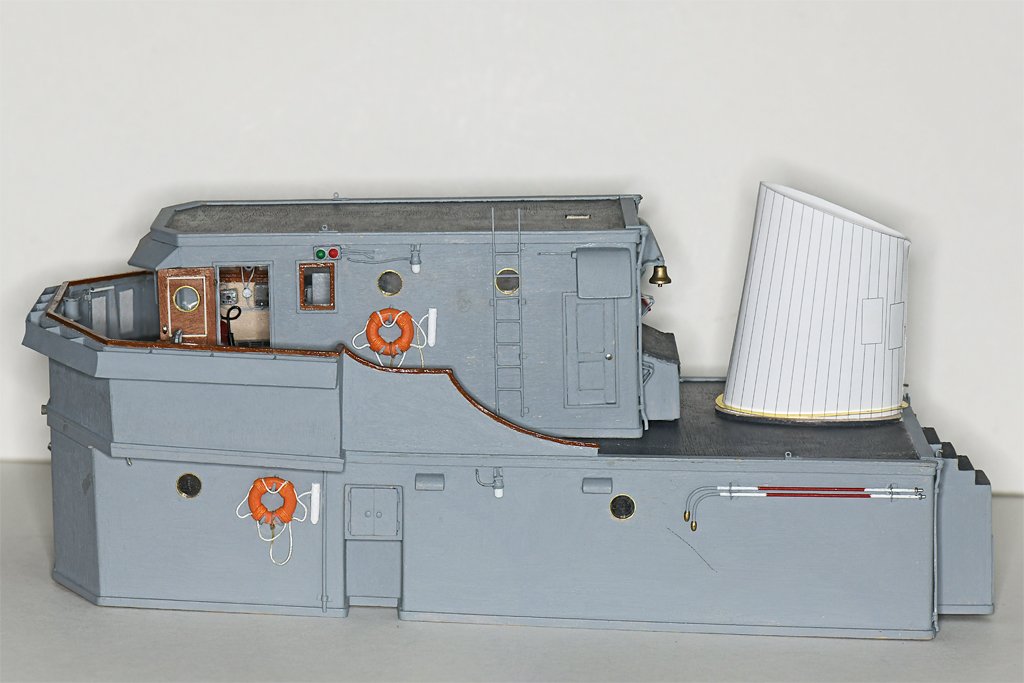
The smoke stack is finished (except for the antenna). I painted the brass with a thin coat of FolkArt all-purpose satin finish sealer. This is what I have been using to seal the wooden surfaces before painting. The instructions on the bottle say it can be used on a "non-porous surface to add slight texture for increased paint adhesion." It is a water-based clear acrylic paint. After the sealer had dried about 40 hours (delayed due to Christmas events) I painted the black top. After that dried overnight I applied masking tape over the black and painted the grey. The paint flowed on smoothly and adhered to the sealer nicely. Neither the paint nor sealer lifted off the brass when the masking tape was removed. Here is a picture of the fire station at the aft end of the main deckhouse. The life jacket locker hangs directly overhead. It was an open space away from passageways where the life jackets could be dumped. However, it was just relatively open! The two sailors are standing on a "portable" (removable) deck section that is directly over the four GMC 6-71 main propulsion diesels. An inclined ladder will lead down to the main deck behind the sailor on the left. When I get around to making the minesweeping gear a small winch will be mounted on the portable deck section. The winch is for handling the large float for the acoustic sweep device. Just outboard to starboard of the winch was a davit, and the acoustic sounder mounted outboard of that. The life jackets would dump on top of the winch and the spaces around it. A hand grenade locker was positioned where the Captain (in dress khakis) is standing. One of the life rafts will be positioned at the aft starboard corner of the deck house. Forward of that was a pyrotechnic locker. There was a narrow walkway between the lockers and life raft leading to the top of the vertical ladder. There really wasn't a lot of bare deck space anywhere on the ship.

- 464 replies
-
- 7
-

-
- minesweeper
- Cape
- (and 1 more)
-
I have the 1989 edition and it is coming apart. I don't know if the later editions would be more durable.
-
Brian, Thanks! This type mechanism was common for life jackets on US Navy ships. The top is a lid that hinges up, allowing life jackets to be tossed in after use. The bottom is a door that hinges down, allowing the life jackets to tumble out on deck. I have studied the blueprints on the Cleveland class cruisers of WWII and the MSI blueprints of the 1950-60s. One thing they have in common is that the lever that pulls down to open the bottom door was held in place by an ordinary US Navy issue 1/2 inch (12.5 mm) fuse clip. Two of these were used in electrical circuits to hold a cylindrical fuse. Just one was used to hold the 1/2 inch diameter life jacket release handle. The MSI lifejacket locker had to be located above a place on the main deck that was open and easy to get to but not in a passageway. As you will see as the build progresses almost the entire main deck was covered with equipment or stowage lockers. About the only place suitable for the life jacket locker was above the fire hose station at the rear of the main deck cabin. And there was nothing else attached to the rear of the stack which was directly above the fire station, so that was a convenient place to mount the locker. The Cape had a crew of 19 enlisted and 3 officers. The life jacket locker held 25 CO2 life jackets and 3 "fibrous glass" life jackets. I guess the three fibrous glass life jackets were for the officers. They didn't need a charged CO2 cylinder. There were 6 spare CO2 life jackets in case some didn't work. The ship also carried two 15 man inflatable life boats and a 12 foot (4 meter) "wherry," a small boat with an outboard motor.
- 464 replies
-
- 8
-
-
- minesweeper
- Cape
- (and 1 more)
-
Sail feedback request, Mondfeld method
Dr PR replied to travis's topic in Masting, rigging and sails
Silkspan is the way to go for sails at the smaller scales (1:48 and smaller). The thinnest grade (SIGST001) is approximately scale thickness for 1:48 to 1:72 scale. When wet it is VERY fragile, but when it is dry it is very tough. It became popular for wing and fuselage coverings on flying model airplanes. Here are some links telling my experiences making sails from it. There was a learning curve, but the results are pretty good. https://modelshipworld.com/topic/19611-albatros-by-dr-pr-finished-mantua-scale-148-revenue-cutter-kitbash-about-1815/?do=findComment&comment=1035898 https://modelshipworld.com/topic/19611-albatros-by-dr-pr-finished-mantua-scale-148-revenue-cutter-kitbash-about-1815/?do=findComment&comment=1035392 https://modelshipworld.com/topic/19611-albatros-by-dr-pr-finished-mantua-scale-148-revenue-cutter-kitbash-about-1815/?do=findComment&comment=1039363 https://modelshipworld.com/topic/19611-albatros-by-dr-pr-finished-mantua-scale-148-revenue-cutter-kitbash-about-1815/?do=findComment&comment=1049586 In my opinion those heavy cloth stitched sails that come with kits look awful! -
The same. If you keep your hands in your pockets there is a much smaller probability of screwing up things. And he's out of uniform. The Captain and XO are wearing dress blues, so that must be the uniform of the day. Fuzz is wearing working khakis (that was our most common daily uniform) and a leather aviator's jacket.
- 464 replies
-
- 4
-
-

-
- minesweeper
- Cape
- (and 1 more)
-
wefalck and FreekS, Thanks for the tips. I don't know if I can buy Zapon varnish in the US. However it appears to be a nitrocellulose solution. Duco cement is nitrocellulose dissolved in acetone. I suppose I could just dilute Duco with more acetone to make a thin nitrocellulose varnish. Createx UVLS clear satin is sold here. I have put a bottle in my Amazon cart for my next order.
- 464 replies
-
- 2
-
-
- minesweeper
- Cape
- (and 1 more)
-
Eberhard, Thanks. The "waxy" dull surface on the brass I am using becomes visually apparent in just a few hours. It turns from very shiny after polishing with #0000 steel wool to a duller yellowish color. I am trying an acrylic sealer as a primer. If that doesn't work I will try shellac. Of course the fogging of brass is familiar to everyone who had to polish brass belt buckles in boot camp!
- 464 replies
-
- 3
-
-
-
- minesweeper
- Cape
- (and 1 more)
-
DD, I too recommend zu Mondfeld's Historic Ship Models as a good first reference. It discusses vessels from all periods and all western nationalities. The key thing to remember about the ropes in a ship's rigging is that they usually were scaled from the main mast diameter at deck level. Generally the same scales were used on all vessels. However, the rope sizes are calculated in circumference. This almost always confuses beginners (it did me)! For example, for hemp rope the main stay may be listed as half the diameter of the main mast. If the mast is two feet diameter (24 inches) the stay dimension will be about 12 inches. This would be a huge rope, if it was the same diameter as the mast. But it is the circumference of the rope that is the same length as half the diameter of the mast. To get the actual diameter of the rope divide the rope circumference by pi (3.14159). So 12/pi = 3.8 inch diameter. Then all other ropes are scaled from the main stay. But the scaling may vary with the date. So if the main stay is 3.8 inch diameter the shrouds would be the same diameter (100%) in the 19th century, but only 62% of the main stay (2.4 inch diameter) in the 18th century. Mondfeld's rigging size tables shorten calculations a bit by calculating the main stay dimension as the mast diameter multiplied by pi/2, or about 0.166 times the mast diameter. This is about the same as dividing by 2, and then dividing by pi. Other authors give calculations that may differ a bit from Mondfeld, but the results are about the same. When scaling down to the model's scale these small differences don't matter - you will have to choose the closest scale rigging to the ideal dimensions. Mondfeld cautions that the scales may vary a bit with nationality, but his tables are a good place to start. And for later 19th century and 20th century ships with steel wire rigging the dimensions should be reduced about 33% from the calculated dimension for hemp. You are starting down a deep rabbit hole!
-
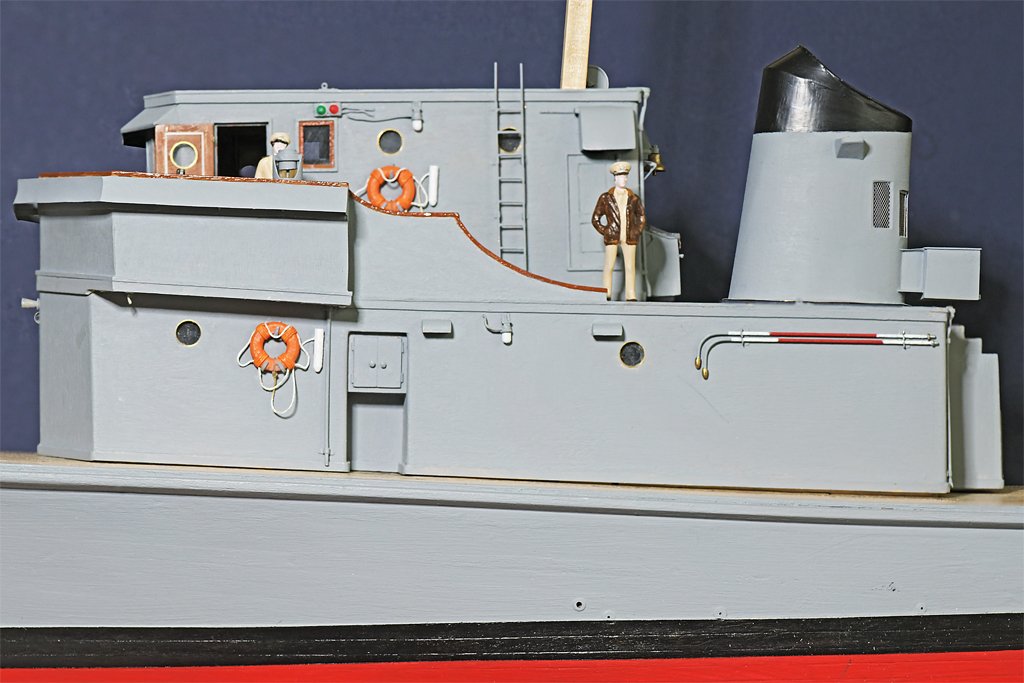
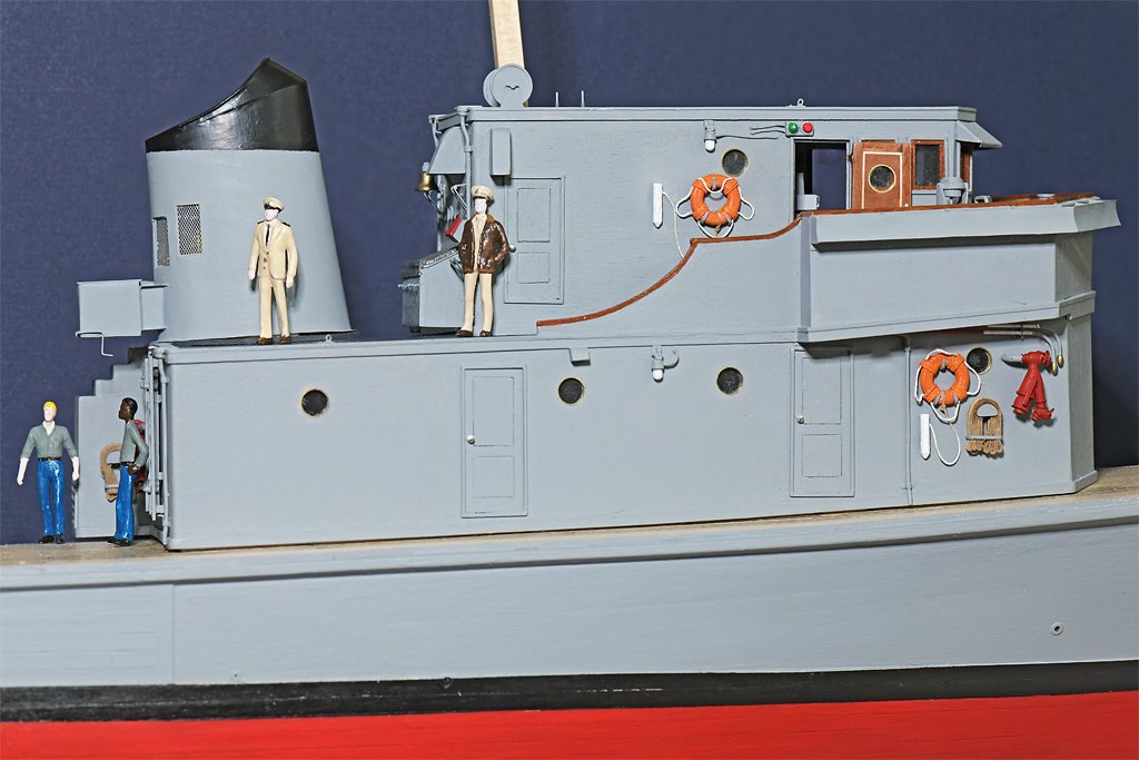
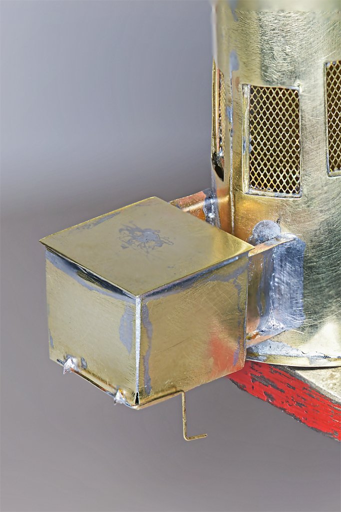
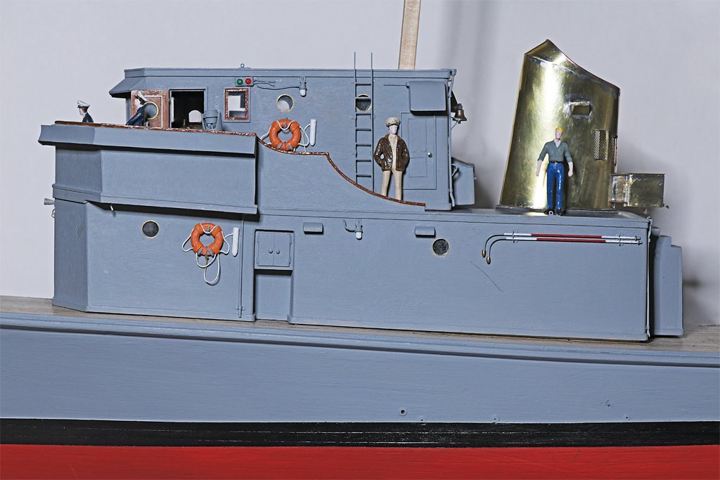
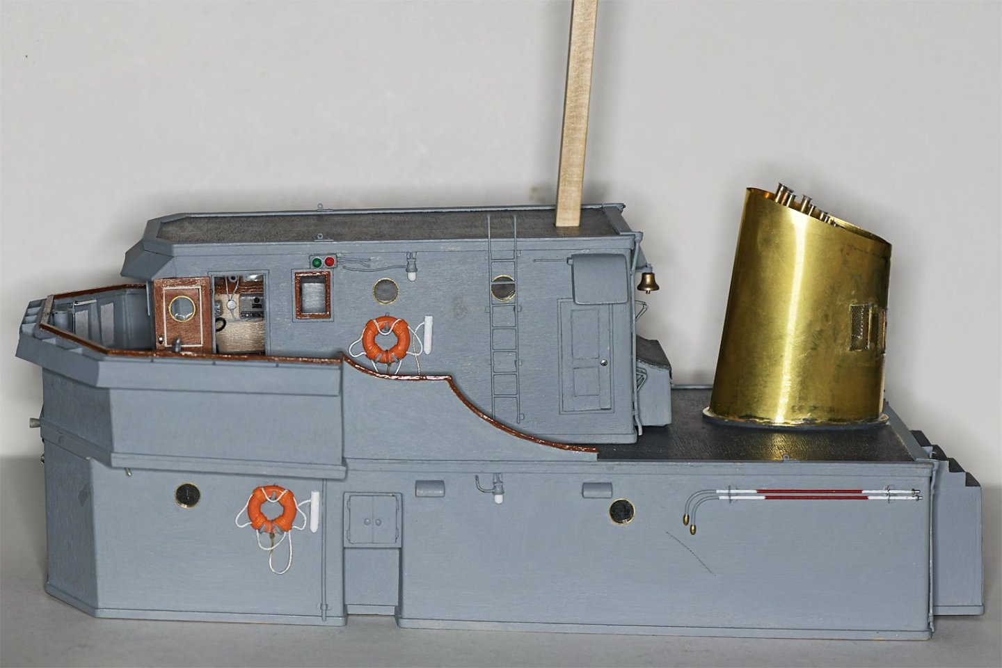
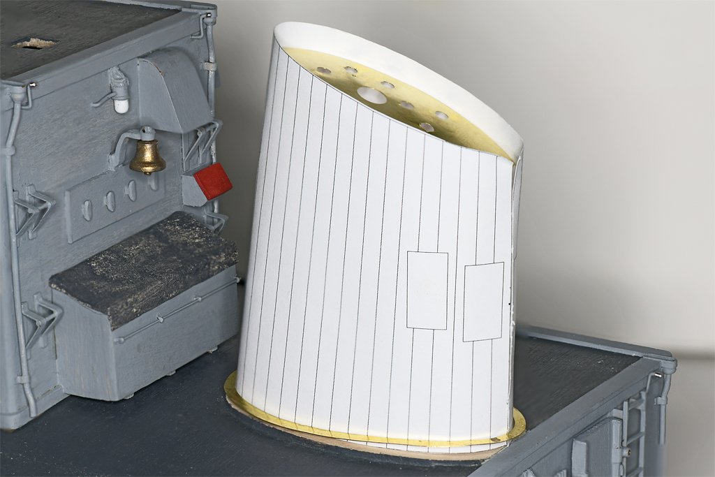
Thanks to everyone for the likes and comments. Keith, we had a great Christmas. Seven great grandkids from 1 year to 14 years, and none was sick! I am finishing up the smoke stack. I made the conical cap for the boiler vent from a brass rod, turning it on my hand drill. The hinges for the diesel exhaust pipe caps were made from 0.010 inch (0.25 mm) styrene strips. First the lower pieces were glued to the brass pipes with CA gel. After the CA set the two hinge strips were glued to the lower piece with plastic model cement. I used a bit of clear acrylic sealer to "glue" the styrene hinge strips to the top of the cap. It probably isn't the most robust assembly, but they are protected by the stack cap. I painted it with the grey paint I am using for the decks. It is Tamiya XF-63 German Grey. I have found that the Tamiya paints do not cover well on brass. This was all washed with water to remove the liquid flux, and then acetone to remove any resin flux and oils. There are three coats of paint on this assembly, each allowed to dry over night, and still there are places the paint just "rolls back" leaving exposed brass. The platform jutting from the side of the stack is a support for a radio antenna. I suppose I could have glued it in place with CA, but the solder will make a stronger attachment. Now I need to make the complex insulators for this antenna and two more. I have the Navy electronics data sheets for the antennas and some photos taken on the ships to show me what they look like and how large they are. It will be an interesting project. But the antennas will be some of the last pieces to go onto the model. The last part of the stack assembly is the life jacket locker that was attached to the lower rear of the stack below the air intake grills. The box is a bit wider than long (about 32" wide x 31" long x 26" high full scale). I folded the box from a single piece of 0.005 inch (0.13 mm) brass sheet and then soldered the edges. A separate 0.010 inch (0.25 mm) thick top plate was soldered on - this hides the folded edges that were a bit rounded. A 0.010 inch brass wire serves as the handle that released the bottom of the locker to dump the life jackets. Here are some photos of the stack in place on the aft end of the O1 level. Now I need to prime the funnel and paint it to hide all of the solder stains in the brass! I probably won't get around to that until next year. HAPPY NEW YEAR!
- 464 replies
-
- 14
-
-

-
- minesweeper
- Cape
- (and 1 more)
-
Do you have a picture of the finished kit so we can see what you are building?
-
Oops -- Repairing broken bowsprit on Cutty Sark
Dr PR replied to Lost and Confused's topic in Masting, rigging and sails
Been there, done that! If it helps any, just think of it as fate giving you the opportunity to do the work better than before. -
When did Ragnar come to the United States? Did he enter at San Francisco or somewhere on the east coast? How did he get here? The reason I ask is that he may have modelled the ship he travelled on. If the family has records of his arrival in the US they may tell what ship he sailed on.
-
There are many opinions about this. However the discussion in this link tells that belaying pins were in use in Europe in the early 1600s: https://modelshipworld.com/topic/21834-more-on-belaying-pins/?do=findComment&comment=653870
- 1 reply
-
- 1
-
-
The ship needs a helm! I certainly wouldn't use water - it might soak into the century dry wood and cause swelling. And as a microbiologist I cringe at the thought of covering anything with spit! Not a good idea in my opinion, even if it does "work." Just brushing with a small stiff brush may be all that is needed. I do this with the end of a vacuum cleaner hose nearby (3-6 inches/75-150 mm). But be careful that some parts - like hatch covers - are not just resting in place unattached. Otherwise you may end up sorting through the dust in the vacuum cleaner bag. If a liquid cleaner is needed to dislodge stuff I think I would apply isopropanol (rubbing alcohol) with a small brush and immediately swab it up with a Q-tip. The alcohol will evaporate quickly. But use it very sparingly and work fast so it doesn't have time to dissolve any finishes (especially shellac). Test this first in an inconspicuous place!
-
Thanks! But it looks a bit nicer after it has been polished with #0000 steel wool! I have added the cap to the stack, and the bead that runs along the top edge of the cap. The edge of the 0.005 inch (0.13 mm) thick stack cap rests precisely on the top edge of the 0.005 inch thick stack shell. And the 0.030 inch (0.76 mm) copper wire bead rests on the top edge of the cap. I know this looks difficult, but it is actually a lot easier than you might think! The trick is pretty simple: start by attaching the two pieces just right at one place. I started at the front edge and used clamps and tape, repositioning until the cap was aligned perfectly at that one spot. Then I applied a bit of liquid citrus solder flux and a tiny amount of solder. GOTCHA! Once the two pieces are fixed together permanently at one spot they can't come apart and it is pretty easy to pull them together correctly at another place a short distance from the first. Then solder another spot, move on a short distance, align them again and solder another spot, and so on. This "stitches" the two pieces together. Just be certain to put heat sink clamps between the new solder place and the previous one to prevent heat from travelling back and unsoldering the previous spot. For the wire bead I modified a small wooden "clothes pin" clamp to have a narrow point with a 0.033 inch (0.84 mm) hole drilled between the two parts of the tip. When this was clamped over the wire and top edge of the cap it held the wire centered on the edge. Because it was wooden I could solder right up to the clamp without soldering it to the assembly. If I was really good at this I could have soldered everything from the inside without leaving the solder stain on the exterior. I have seen some amazing brass locomotives that were soldered together with no solder showing from the outside. But I am not that good. The stack will be painted gray with a black top, so the stain won't be visible in the finished piece. This is how I spent my Christmas day (plus some housekeeping). The Admiral's family all got together last Sunday for an early Christmas, and tomorrow my side of the family has another Christmas with the kids, grandkids and a horde of great grandkids. Happy Holidays!
- 464 replies
-
- 12
-
-
-
- minesweeper
- Cape
- (and 1 more)
-
Harvey, Nice recovery! It looks very nice. Happy holidays!
-
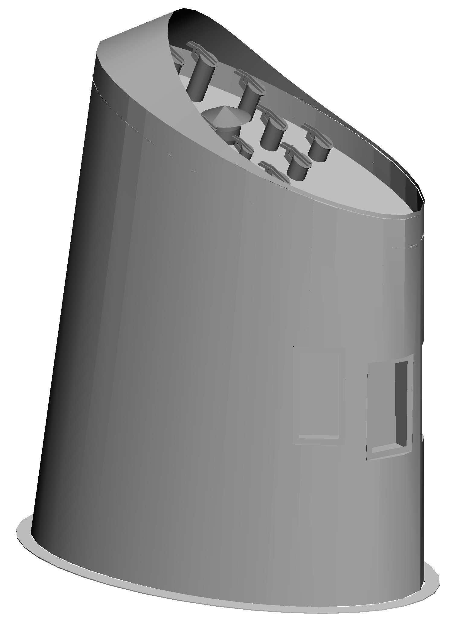
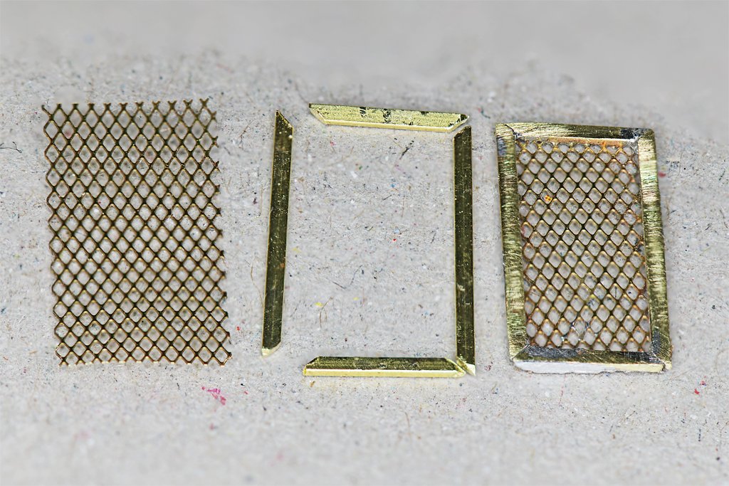
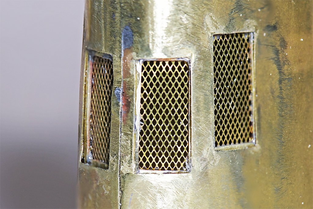
I finally got up the courage to roll the smoke stack shell and add on the base ring and upper plate. I could imagine any number of ways this could go wrong, but it assembled without much trouble! The templates from the 3D CAD model worked perfectly. The shell rolled up to just the right dimensions for the top plate and base ring to fit correctly! First I soldered the 11 vent pipes into the top plate. I still need to make the conical cover for the large boiler vent. And I think I have figured out a way to make the hinges for the cover flaps for the diesel exhaust pipes. The caps are just 0.127 inch/3.2 mm diameter so the hinges will be very small! I had to do a small amount of fitting to get the top plate to squeeze into the shell at a scale 7 inches (0.146 inch/3.7 mm) below the top edge of the shell. Then getting it to stay there while I soldered it in place - without unsoldering any of the exhaust pipes - was an exercise in patience. The next step was to make the intake vent screens on the aft side of the smoke stack. The blueprints call for a rectangular pattern screen with wires spaced 1/2 inch (12 mm) apart. That comes out to 0.0104 inch/0.26 mm square openings with 0.0013 inch/0.033 mm wire. I have three rolls of fine mesh wire screen, one brass with 0.025 inch/0.625 mm squares, another brass with 0.017 inch/0.43 mm squares, and a stainless steel mesh with 0.016 inch/0.42 mm squares. The wire diameters are about 0.004 inch/0.17 mm. These were all oversized and looked too "lumpy" to my eye. Here I departed from true scale. If I was going to have an oversized screen I might as well use a fine photoetch brass screen used for vents in HO scale (1:87) F series diesel engines. I picked up a package of these at our local hobby shop many years ago, thinking they would make nice vent screens for ship models. It has a "X" parallelogram pattern instead of square, with openings 0.030 inch/0.77 mm wide. OK. It isn't to scale, so sue me! I think it looks a lot better than the screen wire. I soldered up four of these 0.51 x 0.26 inch (13.2 x 6.6 mm) vent screens and then glued them inside the vent openings with cyanoacrylate (CA) gel. Next will be the diesel exhaust cap hinges, boiler vent cover, and the cap that fits onto the top edge of the shell. HAPPY HOLIDAYS TO ALL!
- 464 replies
-
- 15
-
-
-
- minesweeper
- Cape
- (and 1 more)
-
Any updates for Pelican?
-
Thanks for posting that fisherman's staysail rigging information. Because it says the sheet leads down to the aftermost deadeye doesn't necessarily mean it is rigged to the deadeye the way shrouds are rigged. I have seen several instances of where a line is just tied off to a deadeye, sometimes below the lower deadeye. The rigging for the tack is interesting. I would like to see a diagram or photo showing how this was set up. Happy Holidays!
-
USS Constitution by mtbediz - 1:76
Dr PR replied to mtbediz's topic in - Build logs for subjects built 1751 - 1800
According to Darcy Lever's The Young Sea Officers Sheet Anchor the tackle you are referring to is called the burton tackle (page 23), especially if it descends from the upper mast top. Sometimes it is just called a mast tackle, especially on the lower masthead. The line from the top is called the tackle pendant. These tackles were used for handling cargo, boats, cannons and other heavy objects. For what it is worth, the heaviest and strongest winch used for handling cargo on US Navy ships is still called the burtoning winch. A swifter is the after shroud if there is an odd number of shrouds. It is fitted over the masthead with an eye splice and the shrouds run down on both sides of the mast to deadeyes like the other shrouds. -
John, Thanks! Brian, The large center pipe is the vent for the heating boiler. The other ten pipes are exhausts for the four main 6-71 diesel engines, the four 6-71 diesel minesweeping generator engines, and two 4-71 diesel ships service generator engines. The diesels each had a muffler in the overheads of the engine rooms with a rats nest of insulated exhaust pipes leading up into the uptake on the main deck level (also the access down into the engine rooms) and then up into the stack.
- 464 replies
-
- 3
-
-
-
- minesweeper
- Cape
- (and 1 more)
-
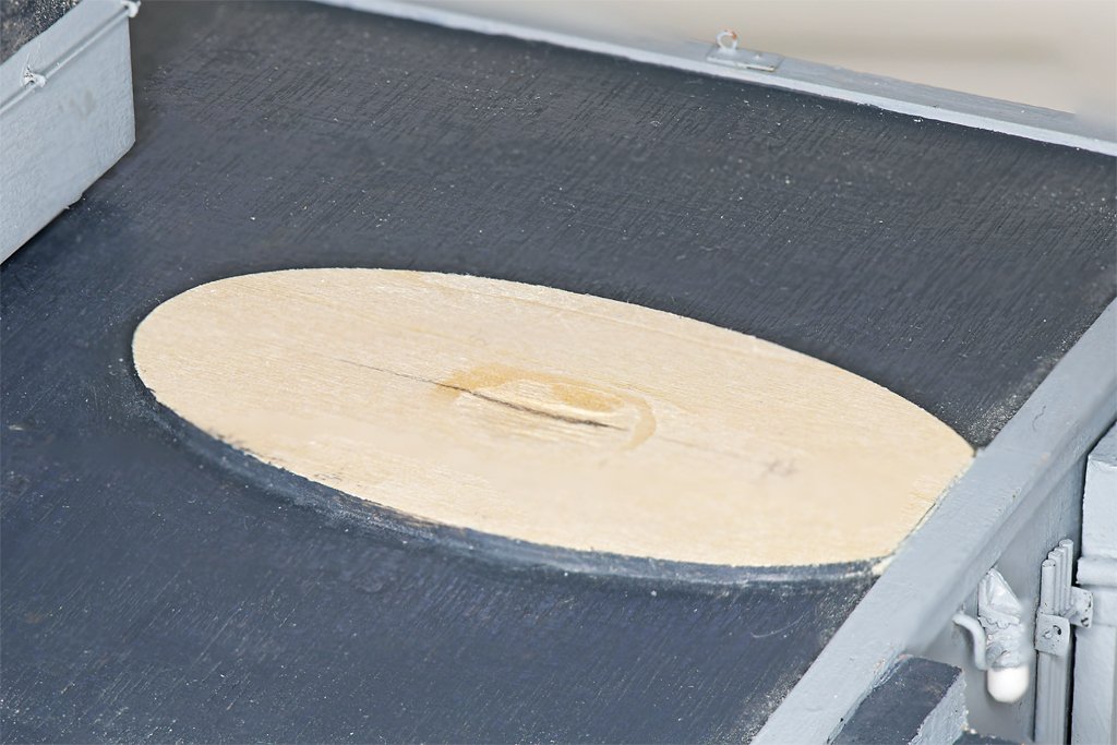
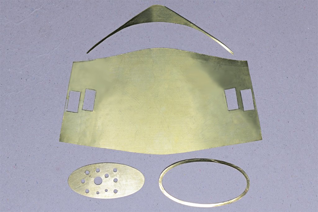
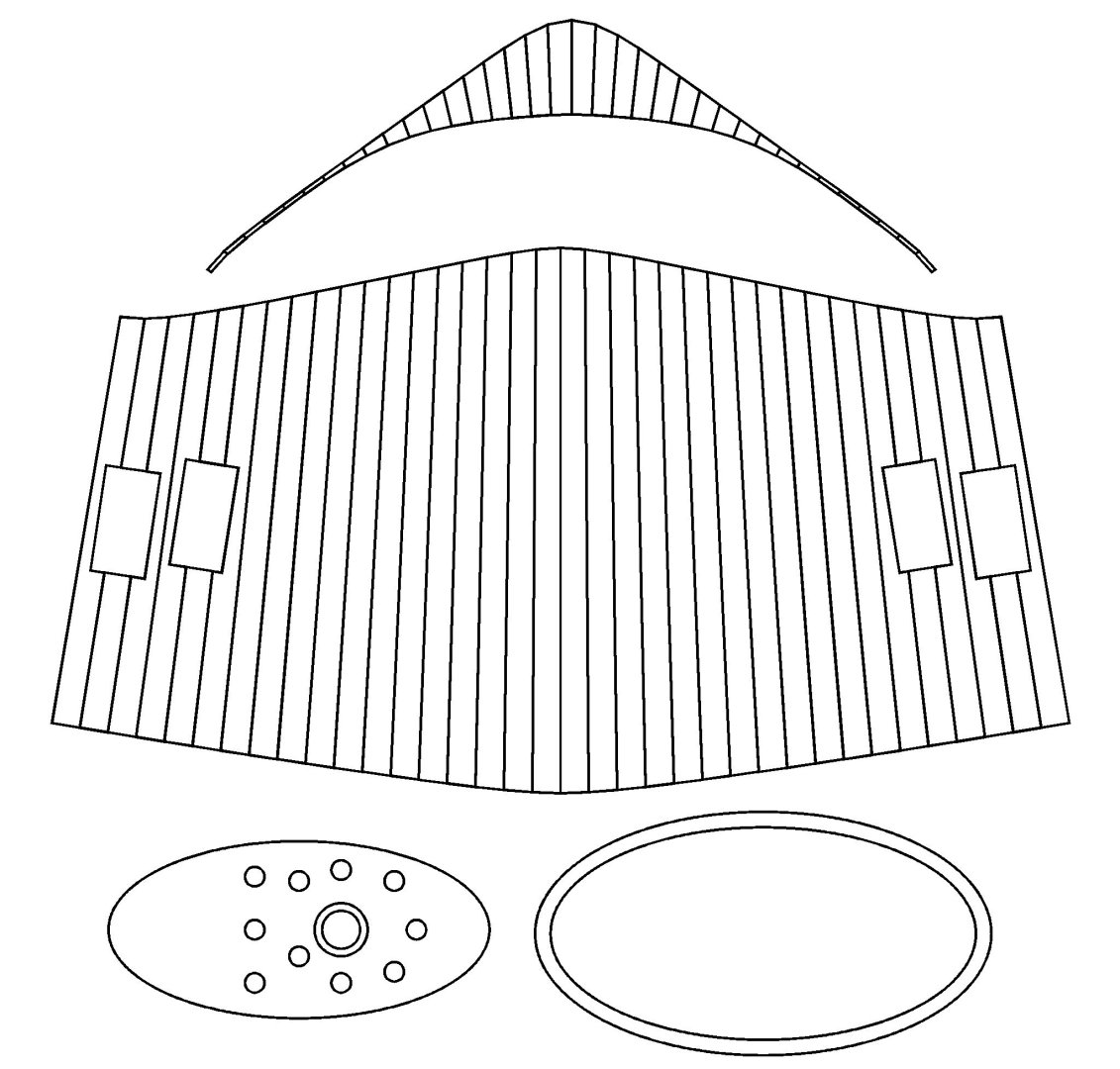
Smoke Stack/Funnel The next "detail" to add to the deck houses is the smoke stack. It is a fairly complicated truncated oval cone. I suppose I could have carved it out of a block of wood, but I wanted to try making it from brass sheet. All this brass work is practice for the machinery on the stern of the ship. First I made a CAD model of the smoke stack. The funnel cap piece was a bit tricky in CAD, but there is no way I could have made it free hand! Then I unfolded the 3D CAD parts to make 2D patterns for the pieces. I made the base for the smoke stack from 1/16 inch (1.6 mm) basswood sheet. It was sanded to the correct thickness (about 0.055 inch/1.4 mm) at the edges, and to fit the curvature of the deck. It was glued in place with Titebond Original glue, and this is where Murphy stepped in to help. While I was working on the other pieces the wood curled up at the edges to a shallow "U" shape. I didn't notice this until the glue had set, so I soaked the glue under the edges with water until it loosened. The wet glue was removed, more fresh glue added, and the thing was weighted down with a small anvil resting on a plywood scrap to force the edges to lie flat. I cut out the oval ring at the base of the stack from 0.005 inch (0.13 mm) brass sheet. Then the oval top plate that holds all the exhaust pipes was made and drilled for the pipes. A paper template for the shell of the stack was rolled up and taped closed to form the oval cone. The paper cone was fit into the base ring and the top plate was slipped into the top of the stack. This assembly fit nicely in place at the rear of the main deckhouse on the O1 level. The paper template seemed to be the correct shape so it was time to cut out the remaining brass pieces. These parts were cut from 0.005 inch (0.13 mm) brass sheet. It is pretty thin, but I think this will be sturdy enough after it is rolled up and the base ring and top plate are soldered in place. I will install the 11 exhaust pipes into the top plate before starting the assembly. They should all have tiny cover pieces, but I doubt that I can make the minute hinge parts shown in the CAD image. That top cap piece will be a bit of a challenge to solder directly onto the top edge of the shell piece. Then a 0.025 inch (0.6 mm) diameter brass wire is to be soldered along the top edge of the cap piece! It will be good soldering practice. I have already done all this once before with the funnels for the USS Oklahoma City CLG-5 model - but at 1:96 scale.

- 464 replies
-
- 10
-
-
-
- minesweeper
- Cape
- (and 1 more)
-
Joggling Deck Planks
Dr PR replied to DGraley's topic in Building, Framing, Planking and plating a ships hull and deck
Here is a drawing from the Anatomy of Ships book on the Beagle. This shows nibbing and not hooking. You can see the planks near the bow were not nibbed because the met the margin board at less than a 45 degree angle. The nibbed planks seem to be cut into the margin board about half a plank width. It is difficult to see a consistent angle for the nib cut, but it doesn't seem to be cut in perpendicular to the margin board edge. Most appear to b cut perpendicular to the plank edge. This came from usedtosail's Beagle build: https://modelshipworld.com/topic/37665-hms-beagle-by-usedtosail-occre-160/?do=findComment&comment=1083788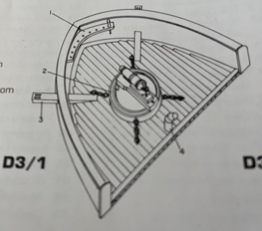
-
Joggling Deck Planks
Dr PR replied to DGraley's topic in Building, Framing, Planking and plating a ships hull and deck
The purpose of trimming the ends of planks is to avoid sharp points that might foul lines or break off and leave a gap in the planking. Basically, if the point on the end of a plank will be sharper (less) than 45 degrees the plank should be trimmed. Planks that fit up to the margin boards with greater than a 45 degree angle do not have to be trimmed. At least that is the way is was done in the 20th century on US Navy ships. But I have seen some models where an attempt was made to nib every plank, even where the angles were much greater than 45 degrees. Check to see what Royal Navy practice was in the 1800s. For "nibbing" planks into the margin board the important thing to remember is that the cut into the margin board for a new plank starts where the outboard edge of the last laid plank meets the margin board. Then you cut into the margin board 1/3 to 1/2 a plank width. From there the cut angles back to where the outboard edge of the new plank meets the edge of the margin board. The length of the outboard edge of the nib is different for every plank. The length of that first nibbing cut seems to vary from vessel to vessel (model to model). Some people cut 1/3 of a plank width, some cut 1/2 the plank width. But the cut depth should be the same on all nibs on a vessel. The modern Navy ships I served on had 1/2 plank width nibs, but it seems older sailing vessels may have had 1/3 plank width nibs - at least some modelers do it this way. See if you can find a reference for the Beagle. The angle of the nib cut also varies. Some modelers make the cut perpendicular to the edge of the plank - this would be the same for all planks. Others seem to make the cut perpendicular to the edge of the margin board, but this means the angle of the cut on the end of the plank would be different for each plank. I know of no reference for this practice, but it may have been used on some vessels. Again, see if you can find a reference for the Beagle. This is a link to how I nibbed the planks on my topsail schooner build: https://modelshipworld.com/topic/19611-albatros-by-dr-pr-finished-mantua-scale-148-revenue-cutter-kitbash-about-1815/?do=findComment&comment=605072 I used black construction paper for the grout between planks. Some people use pencil and some don't model the grout. Just about everyone seems to have their own opinions about grout and whether to model it. ***** Older sailing vessels (pre 1800) seem to have used "hooking" instead of nibbing. In this case an extra wide plank was used where the plank run encountered the margin board. Each new plank was cut into the inboard extra wide plank by about half a plank width, and not into the margin board. The wide plank was trimmed back to the width of a normal plank from the "hook" that was formed on the end that met the margin board. The hook planks were shaped to fit the curvature of the margin board, and there were no cuts into the margin board. To do this properly you need a supply of extra wide planks for the ends of the plank runs, and ordinary width planks. For me this is trickier than simple nibbing. There are example of hooking on the forum, but I don't have a good link. Maybe someone else can provide a link.