HOLIDAY DONATION DRIVE - SUPPORT MSW - DO YOUR PART TO KEEP THIS GREAT FORUM GOING! (89 donations so far out of 49,000 members - C'mon guys!)
×


Dr PR
-
Posts
2,444 -
Joined
-
Last visited
Content Type
Profiles
Forums
Gallery
Events
Everything posted by Dr PR
-
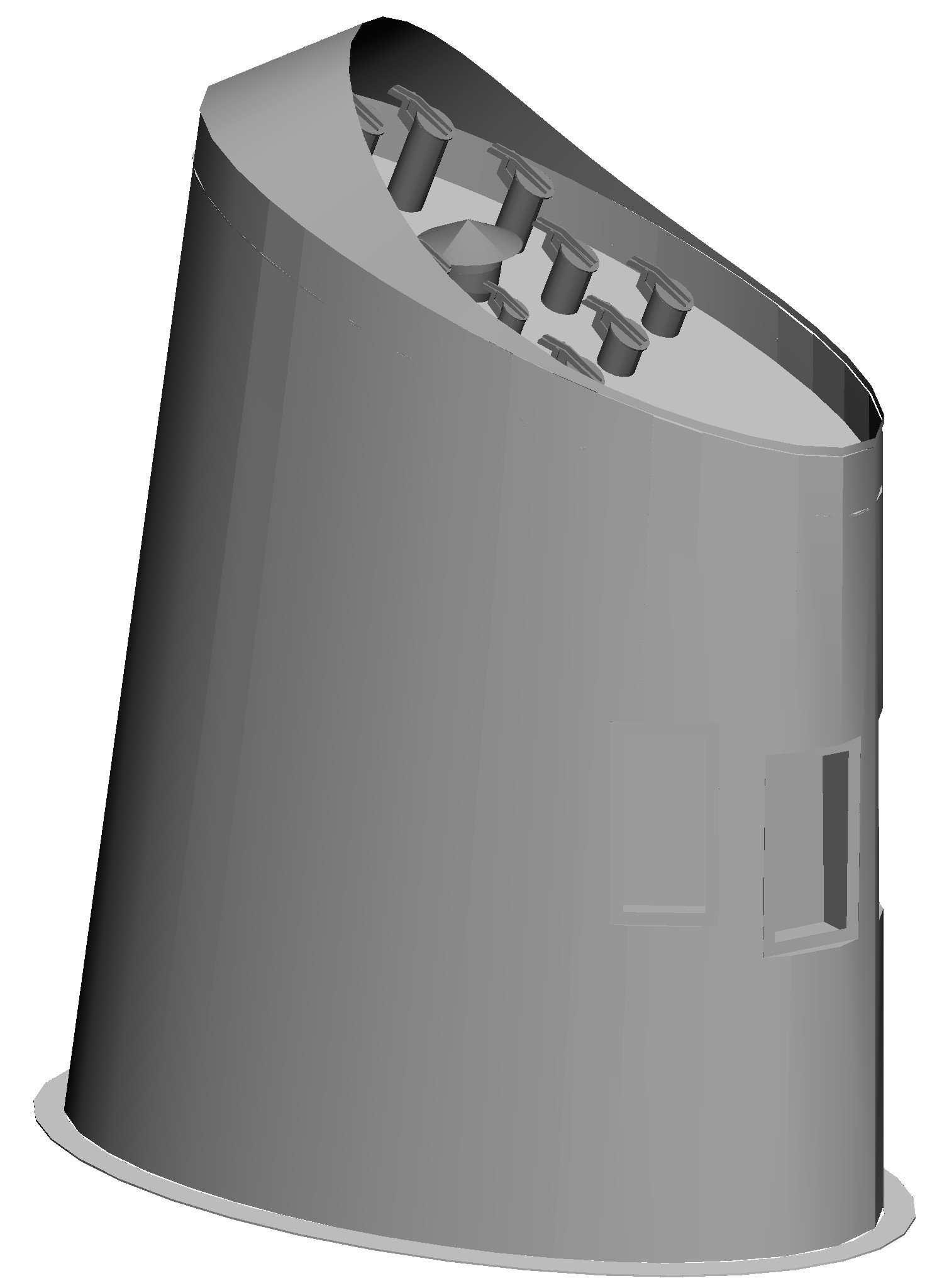
 John, Thanks! Brian, The large center pipe is the vent for the heating boiler. The other ten pipes are exhausts for the four main 6-71 diesel engines, the four 6-71 diesel minesweeping generator engines, and two 4-71 diesel ships service generator engines. The diesels each had a muffler in the overheads of the engine rooms with a rats nest of insulated exhaust pipes leading up into the uptake on the main deck level (also the access down into the engine rooms) and then up into the stack.
- 465 replies
-
- 3
-

-

-
- minesweeper
- Cape
- (and 1 more)
-
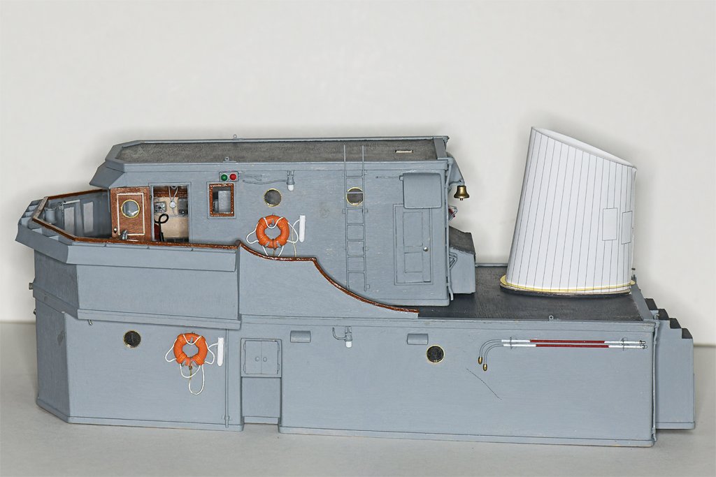
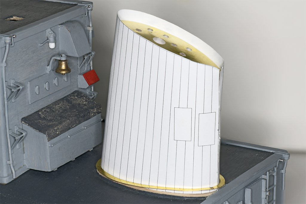
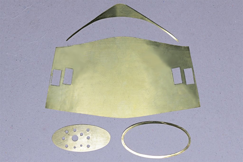
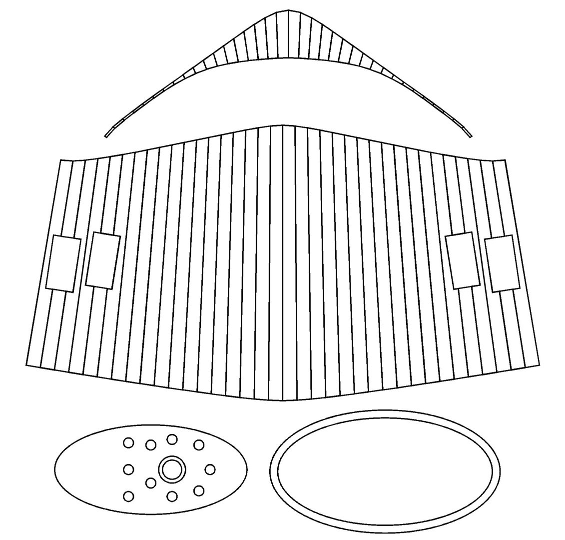
Smoke Stack/Funnel The next "detail" to add to the deck houses is the smoke stack. It is a fairly complicated truncated oval cone. I suppose I could have carved it out of a block of wood, but I wanted to try making it from brass sheet. All this brass work is practice for the machinery on the stern of the ship. First I made a CAD model of the smoke stack. The funnel cap piece was a bit tricky in CAD, but there is no way I could have made it free hand! Then I unfolded the 3D CAD parts to make 2D patterns for the pieces. I made the base for the smoke stack from 1/16 inch (1.6 mm) basswood sheet. It was sanded to the correct thickness (about 0.055 inch/1.4 mm) at the edges, and to fit the curvature of the deck. It was glued in place with Titebond Original glue, and this is where Murphy stepped in to help. While I was working on the other pieces the wood curled up at the edges to a shallow "U" shape. I didn't notice this until the glue had set, so I soaked the glue under the edges with water until it loosened. The wet glue was removed, more fresh glue added, and the thing was weighted down with a small anvil resting on a plywood scrap to force the edges to lie flat. I cut out the oval ring at the base of the stack from 0.005 inch (0.13 mm) brass sheet. Then the oval top plate that holds all the exhaust pipes was made and drilled for the pipes. A paper template for the shell of the stack was rolled up and taped closed to form the oval cone. The paper cone was fit into the base ring and the top plate was slipped into the top of the stack. This assembly fit nicely in place at the rear of the main deckhouse on the O1 level. The paper template seemed to be the correct shape so it was time to cut out the remaining brass pieces. These parts were cut from 0.005 inch (0.13 mm) brass sheet. It is pretty thin, but I think this will be sturdy enough after it is rolled up and the base ring and top plate are soldered in place. I will install the 11 exhaust pipes into the top plate before starting the assembly. They should all have tiny cover pieces, but I doubt that I can make the minute hinge parts shown in the CAD image. That top cap piece will be a bit of a challenge to solder directly onto the top edge of the shell piece. Then a 0.025 inch (0.6 mm) diameter brass wire is to be soldered along the top edge of the cap piece! It will be good soldering practice. I have already done all this once before with the funnels for the USS Oklahoma City CLG-5 model - but at 1:96 scale.

- 465 replies
-
- 10
-
-
-
- minesweeper
- Cape
- (and 1 more)
-
Joggling Deck Planks
Dr PR replied to DGraley's topic in Building, Framing, Planking and plating a ships hull and deck
Here is a drawing from the Anatomy of Ships book on the Beagle. This shows nibbing and not hooking. You can see the planks near the bow were not nibbed because the met the margin board at less than a 45 degree angle. The nibbed planks seem to be cut into the margin board about half a plank width. It is difficult to see a consistent angle for the nib cut, but it doesn't seem to be cut in perpendicular to the margin board edge. Most appear to b cut perpendicular to the plank edge. This came from usedtosail's Beagle build: https://modelshipworld.com/topic/37665-hms-beagle-by-usedtosail-occre-160/?do=findComment&comment=1083788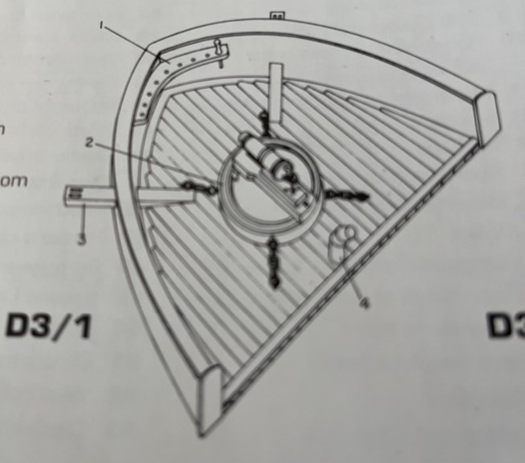
-
Joggling Deck Planks
Dr PR replied to DGraley's topic in Building, Framing, Planking and plating a ships hull and deck
The purpose of trimming the ends of planks is to avoid sharp points that might foul lines or break off and leave a gap in the planking. Basically, if the point on the end of a plank will be sharper (less) than 45 degrees the plank should be trimmed. Planks that fit up to the margin boards with greater than a 45 degree angle do not have to be trimmed. At least that is the way is was done in the 20th century on US Navy ships. But I have seen some models where an attempt was made to nib every plank, even where the angles were much greater than 45 degrees. Check to see what Royal Navy practice was in the 1800s. For "nibbing" planks into the margin board the important thing to remember is that the cut into the margin board for a new plank starts where the outboard edge of the last laid plank meets the margin board. Then you cut into the margin board 1/3 to 1/2 a plank width. From there the cut angles back to where the outboard edge of the new plank meets the edge of the margin board. The length of the outboard edge of the nib is different for every plank. The length of that first nibbing cut seems to vary from vessel to vessel (model to model). Some people cut 1/3 of a plank width, some cut 1/2 the plank width. But the cut depth should be the same on all nibs on a vessel. The modern Navy ships I served on had 1/2 plank width nibs, but it seems older sailing vessels may have had 1/3 plank width nibs - at least some modelers do it this way. See if you can find a reference for the Beagle. The angle of the nib cut also varies. Some modelers make the cut perpendicular to the edge of the plank - this would be the same for all planks. Others seem to make the cut perpendicular to the edge of the margin board, but this means the angle of the cut on the end of the plank would be different for each plank. I know of no reference for this practice, but it may have been used on some vessels. Again, see if you can find a reference for the Beagle. This is a link to how I nibbed the planks on my topsail schooner build: https://modelshipworld.com/topic/19611-albatros-by-dr-pr-finished-mantua-scale-148-revenue-cutter-kitbash-about-1815/?do=findComment&comment=605072 I used black construction paper for the grout between planks. Some people use pencil and some don't model the grout. Just about everyone seems to have their own opinions about grout and whether to model it. ***** Older sailing vessels (pre 1800) seem to have used "hooking" instead of nibbing. In this case an extra wide plank was used where the plank run encountered the margin board. Each new plank was cut into the inboard extra wide plank by about half a plank width, and not into the margin board. The wide plank was trimmed back to the width of a normal plank from the "hook" that was formed on the end that met the margin board. The hook planks were shaped to fit the curvature of the margin board, and there were no cuts into the margin board. To do this properly you need a supply of extra wide planks for the ends of the plank runs, and ordinary width planks. For me this is trickier than simple nibbing. There are example of hooking on the forum, but I don't have a good link. Maybe someone else can provide a link. -
Nice work! Doing good work in a situation where everything fits together orthogonally is relatively easy. Fitting things together where all the angles are different and curved surfaces are involved requires skill and a LOT of patience! Card templates help reduce the amount of waste of good materials. Enjoy your holidays with the grandkids.
-
I put dilute white glue on the ratlines after it has been tied, and hang a wire hook with a light weight attached (small clamp) to make the catenary droop. Leave the weights on until the glue dries and then move on to another catenary. The white (school) glue dries without a stain. But if you are going to paint the ratlines you can use any glue.
-
Paul, Very nice. Now have a merry holiday season!
-
John, Yes. I was a 120 day wonder (from Naval Officer Candidate School) and knew nothing of mine warfare when I reported to the Cape. Like 2nd Lt Fuzz in the Beetle Baily cartoon. I had some schooling for my new job on the USS Oklahoma City CLG-5. I did a better job there!
- 465 replies
-
- 3
-
-
- minesweeper
- Cape
- (and 1 more)
-
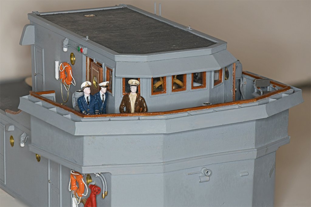
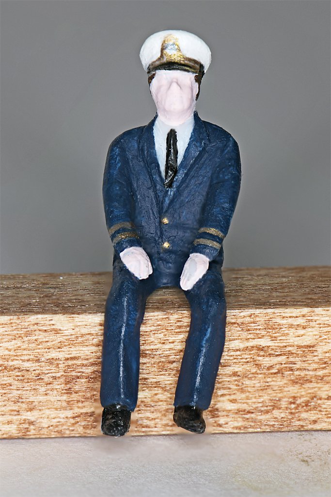
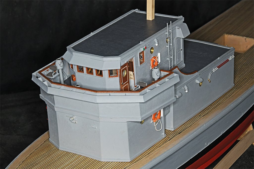
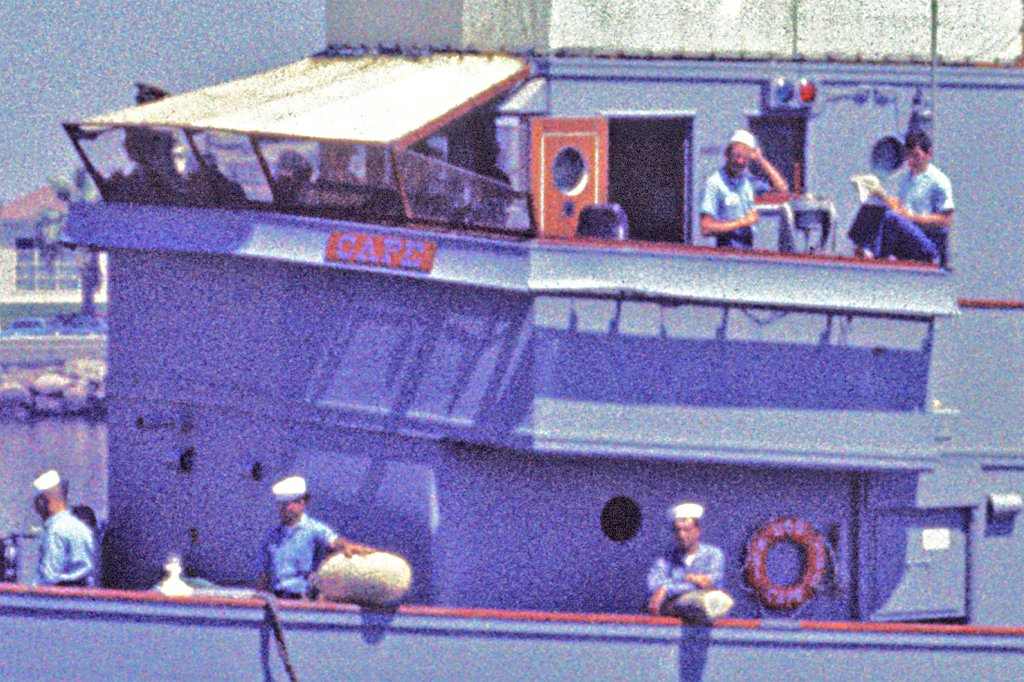
A number of things have kept me away from the Cape model over the last couple of weeks. One was an experiment to see if I could make some 1:48 scale crew figures for the Cape. Here is a link with details about the figures. https://modelshipworld.com/topic/1006-in-need-of-shipyard-workers-or-boats-crewmembers/?do=findComment&comment=1124933 I made two enlisted men and four officers, plus one female "Rosie the Riveter" figure for comparison. The officers were experiments with different dress and working uniforms. They won't all be used on the model. Here you see Captain Fred (seated), Devine Dave and Ensign Fuzz on the Cape's bridge. Dave's uniform had a lot of sand on it - he must have just gotten back from surfing.

- 465 replies
-
- 10
-
-
-
- minesweeper
- Cape
- (and 1 more)
-
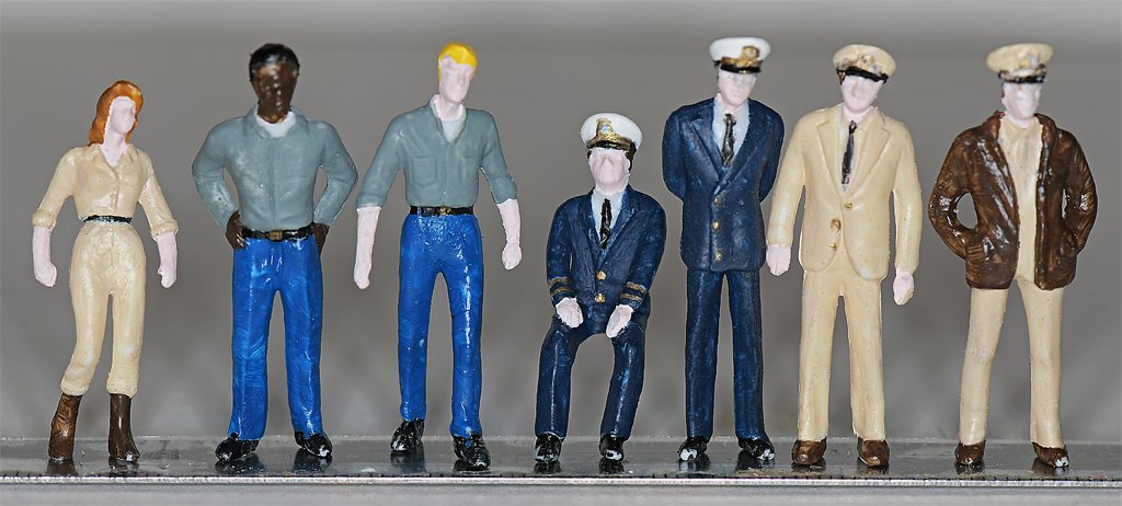
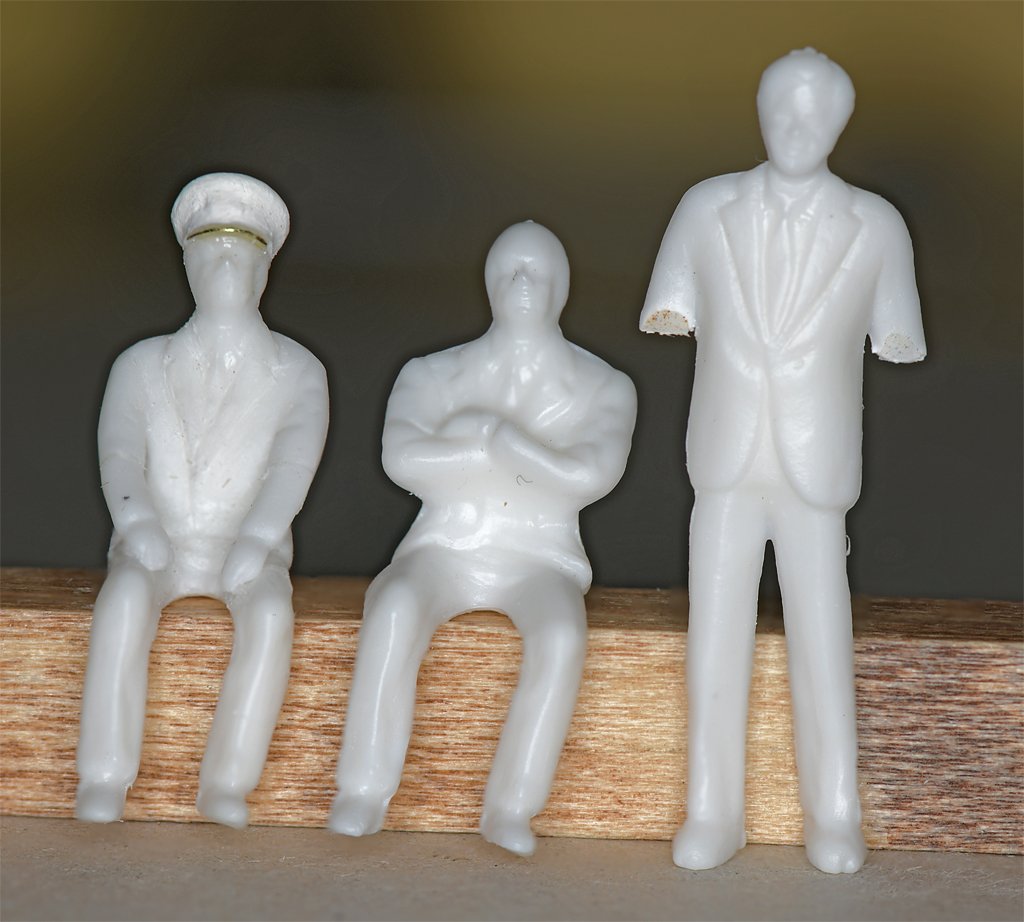
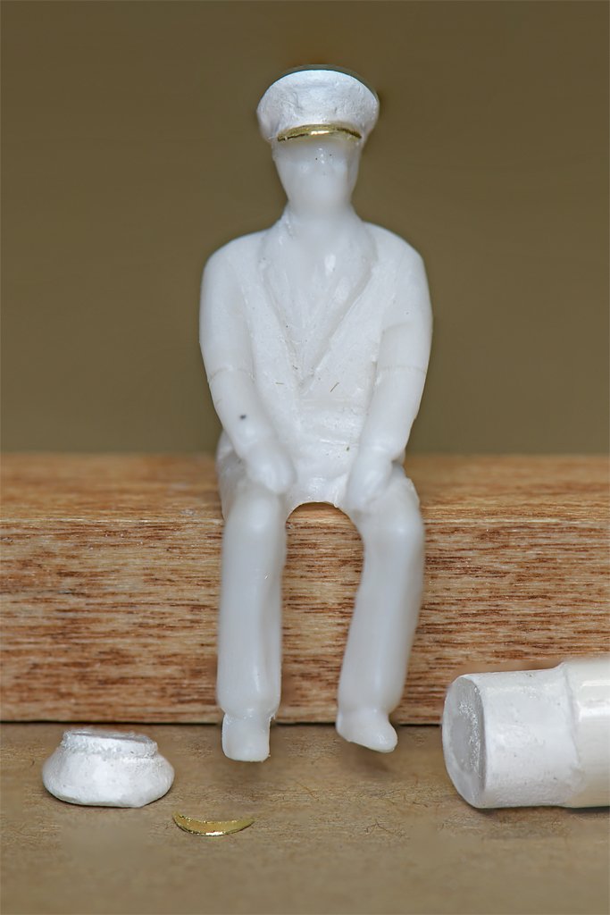
I am modelling in 1:48 or 1:50 scale (O scale) and have had problems finding suitable nautical figures. I still don't have a source of good sailing ship era figures. But I did notice a 50 pieces set of 1:50 figures for US$14.99: https://www.amazon.com/dp/B0CSC79VSQ?ref_=pe_123509780_1038749300_t_fed_asin_title&th=1 There are seven different male figures and five different female figures. One of each is seated. At 1:50 the males are about 5'-8" to 6'-2" (1.7 to 1.9 meters) and the women are about 5'-2" to 5'-4" (1.5 to 1.6 meters). These might be typical people found in a railway station or department store. They are made of a fairly soft white plastic - I assume it is styrene. It glues well with plastic cement. I found six of the male figures that were easily painted to represent US Navy sailors for the 1960-1970 period I am modelling. Two were painted as enlisted men and four were painted in various officer's uniforms. Some of the "officers" could be painted as enlisted. I also painted one of the women as a yard worker - maybe Rosie the Riveter - for comparison. I wanted to use the seated male figure for the Captain on the USS Cape MSI-2 model I am making. However, the seated man had folded arms and looked rather strange. In addition, his posterior/legs were too broad to fit into the Captain's chair. I heated the figure with a hair dryer and squeezed the legs closer together. Then some material was filed away from the outside of the thighs until the figure fit into the chair. The arms were a bigger problem. I used files and knives to cut away the arms below the elbows. Then the remaining plastic was shaped to create the lapels of the officer's dress blue uniform. Well, close to what it should be at least. Then the arms were cut off above the elbows on one of the standing male figures. These were shaped and glued onto the stubs of the arms on the seated figure. They fit nicely with a bit of shaping with small files. No putty or filler was needed. Then I made an officer's cap from styrene rod, with a brim fashioned from scrap 0.003 inch (0.08 mm) brass sheet. So here is an inexpensive way to get a few 1:50 scale modern era Naval figures with a little bit of reshaping and add-ons.


-
Are you going to let Benji play with the trains, Grampa? I had some old Lionel trains from when I was a kid - recovered from my folk's storage shed. We put them up around the Christmas tree and the grandkids ran the wheels off of them.
-
I usually use Squadron white putty. It dries quickly - 30 minutes. It sands easily. But it is chalky white and not very hard, so it is best for filling small holes and cracks up to about a millimeter wide. For narrow cracks in wood I use a glue mixed with sanding dust from the wood to be filled. Duco Cement is colorless nitrocellulose in acetone and makes a nice hard filler when mixed with wood. SigBond or Titebond aliphatic resins are white or pale yellow when dry so they changed the wood filler color a bit. Elmer's school glue is white, but it dries colorless. These all set up in 20-30 minutes, but need to sit over night to harden.
-
Very nice! The sails look good. And a metal film can! That goes back quite a while.
-
This is a beautiful ship! I will be watching to see how you rig the fisherman's staysail. What little I have found showed the sheets belayed to cleats on the boom. But your photos seem to show it belayed to the bulwark. I suppose it could be rigged either way depending upon how they were sailing.
-
Kurt, Willapa Bay is on the West Coast of Washington, just north of the Columbia River. There is no clear weather half the year. That lumber would have sat out in the rain at the mill for some time before being loaded (probably in the rain). That's a good photo of a loaded lumber schooner. It always amazes me that they floated at all! It has a high center of gravity, and that means it will roll a lot in swells. And it will be heading south along the Pacific Coast to California for about 500 miles with swells parallel to the coast all the way. That's several days rolling in the troughs between swells. It would be a rough ride in clear weather!
-
Repurposing Pool Cue Lathes?
Dr PR replied to Rich Sloop's topic in Modeling tools and Workshop Equipment
I used to use my drill as a "lathe" and turn masts and spars with files and sandpaper. But when I started my topsail schooner build I decided to get serious about mast construction. Sailing ship's masts were not cylinders or cones and had a lot of faceted sections. Here is a link to the traditional method of mast making: https://modelshipworld.com/topic/19611-albatros-by-dr-pr-finished-mantua-scale-148-revenue-cutter-kitbash-about-1815/?do=findComment&comment=908539

-
I don't know ... I was brand new once, and it has taken me 80 years to achieve this old and worn look. Not much of a challenge though! Your model looks really nice!
-
I was about 6 when I started building balsa airplane kits. These used very thin sheet wood that had to be rolled and curved to make the fuselage and wings, and it was pretty tricky. Really out of my class at the time. They weren't a thing of beauty when I finished them, but I enjoyed building them. At about 7-8 I saw my first plastic model (panther jet - probably Monogram) and I was hooked. I had a fleet of 18 plastic ships (mostly Revell) and a bunch of airplanes while in grade school. I built three or four plastic sailing ships with minimal kit rigging. When I was about 10 I wanted a model of a schooner but there were no kits in my hometown hobby shops (mid 1950s and no model magazines or Internet). Our city library had no books on ship modelling. So I built my first scratch build out of balsa based on sketches of schooners from television ("Adventures in Paradise"). That was followed a year later with a scratch built 40 foot Chris Craft cabin cruiser like one of Mom's friends had. When they visited our lakefront place I got to drive it! Again, no plans, just sketches. I used a motor drive and propeller from a Lindberg destroyer kit. So you shouldn't rush or delay kids if they are interested in ship models. 10-12 would have been way too late for me! Just encourage them if they show some interest and offer help if they need it. They will either try to build something or just forget it. If you are going to start with a wooden kit, make it very simple, like a canoe kit, or one of the Vanguard wooden boat kits (the 18 foot cutter was pretty easy). There is a lot more to learn with wooden builds than something simple like gluing pre-shaped plastic pieces together. **** Let me stress that there is no "one size fits all" age for kids to start modelling. Watch them, and if they like using their hands to make things they will be ready for some level of modelling. If they would rather read or play video games you will be wasting your time trying to introduce them to modelling.
-
John and Steve, Thanks for the compliments. And thanks to everyone for the likes.
- 465 replies
-
- 2
-
-
- minesweeper
- Cape
- (and 1 more)
-
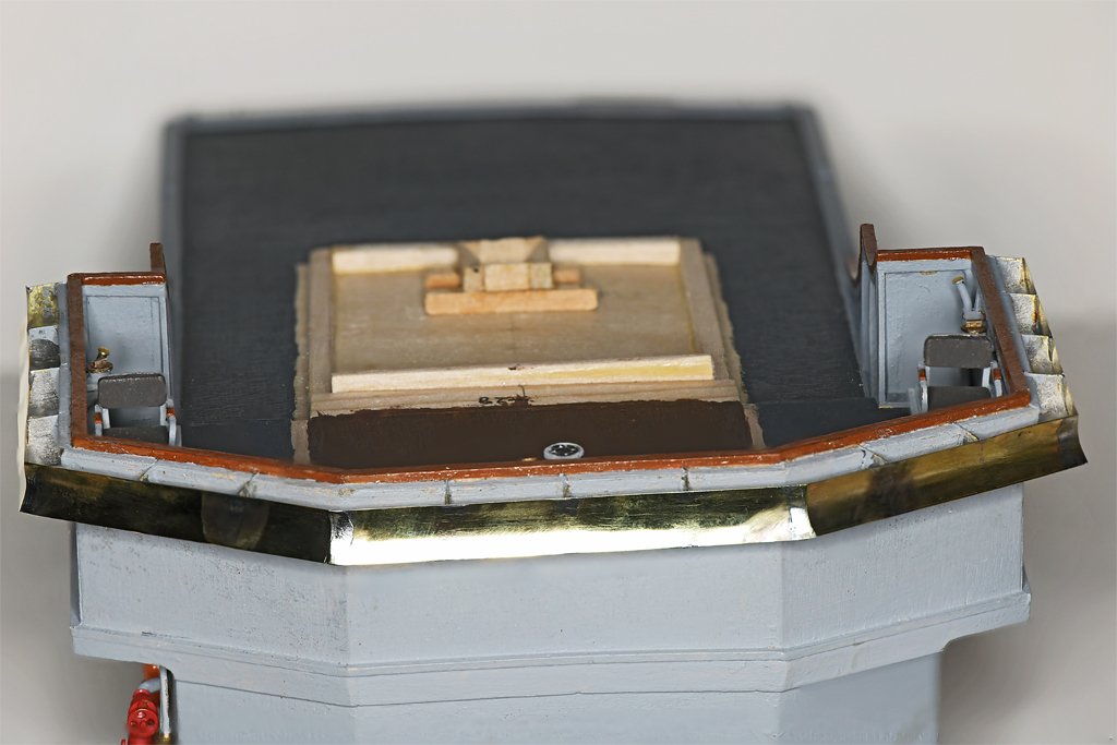
Final venturi work. For all the worrying I did about making the venturis, I think they came out pretty nice! They seem to be very sturdy. The vents and horn on the face of the deckhouse complete (I think) all the details on the sides of the deck houses. But I still need to make the name boards.
- 465 replies
-
- 16
-
-
- minesweeper
- Cape
- (and 1 more)
-
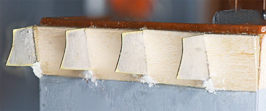
First I painted the chokes and supports. Then I cut cardboard templates for the sections of the venturis. This let me make an approximation of the lengths and angles for the parts. Then I started cutting pieces out of 0.005 inch (0.13 mm) brass sheet. This was frustrating! I used the shear to cut the strips, and it was nearly impossible to make multiple strips of the same width throughout the entire length. I cut eleven 4-6 inch (100-150 mm) long strips in all, and only four were the desired 0.260 inch (6.6 mm) width! I debated whether to use CA glue or to solder the strips onto the supports. CA would be faster and easier, but it is somewhat brittle and might break if the venturis were hit. Soldering would be stronger and less susceptible to breaking. So I chose soldering. It went pretty smoothly, with only one of the supports being knocked off (twice) before everything was all together. Now I just need a bit more clean up to remove excess glue and solder, and then paint. The "mahogany" cap rail on the bulwarks came out a bit worse for wear while I was installing the venturis and needs another coat of paint.
- 465 replies
-
- 11
-
-
- minesweeper
- Cape
- (and 1 more)
-
I don't know when venturis started appearing on US Navy ships. I do know that we didn't have them on the USS Oklahoma City CLG-5 while I was aboard. I stood bridge watches in heavy weather and realized their absence when standing on the open bridge wings. But they were added at my last in port period (March-April 1972). I noticed the new venturis as I was departing the ship the last time in early April 1972. I posted the photo of the Cape's venturi supports in post #424. This was my first photo of the Cape taken the day I reported aboard in April 1969. But this wasn't the initial installation. The blueprint showing the venturi construction is marked "AS CONSTRUCTED PLAN" and dated 18 Sep 1959.
- 465 replies
-
- 3
-
-
- minesweeper
- Cape
- (and 1 more)
-
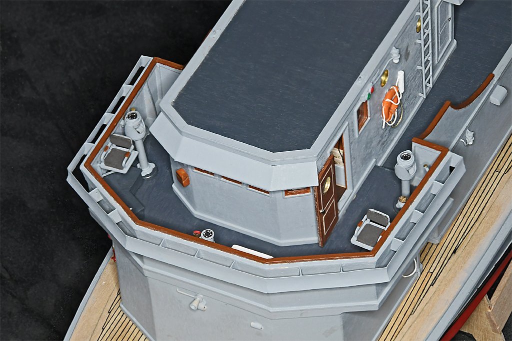
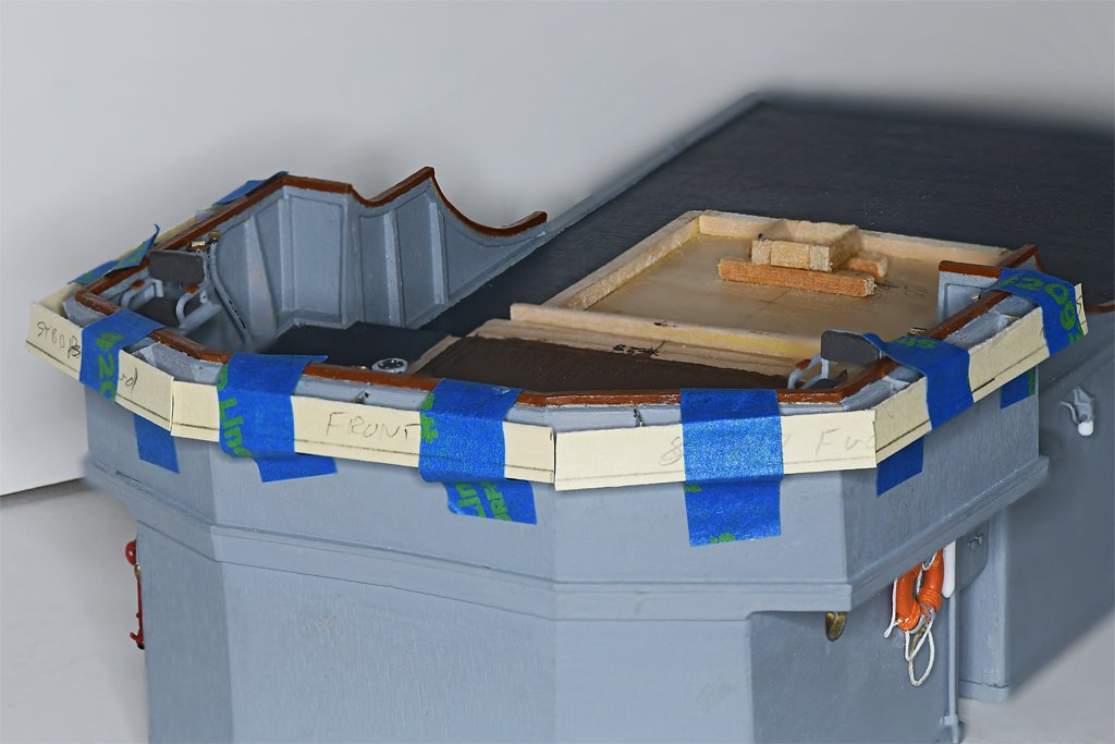
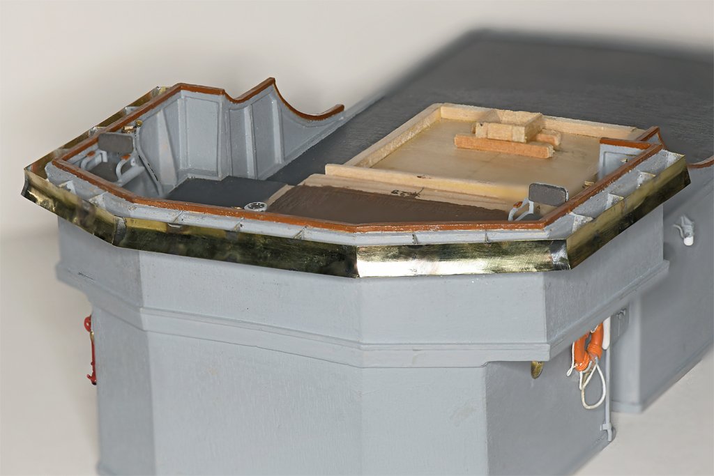
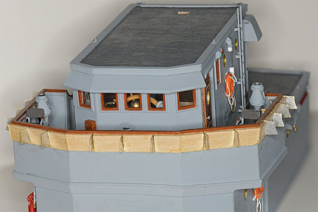
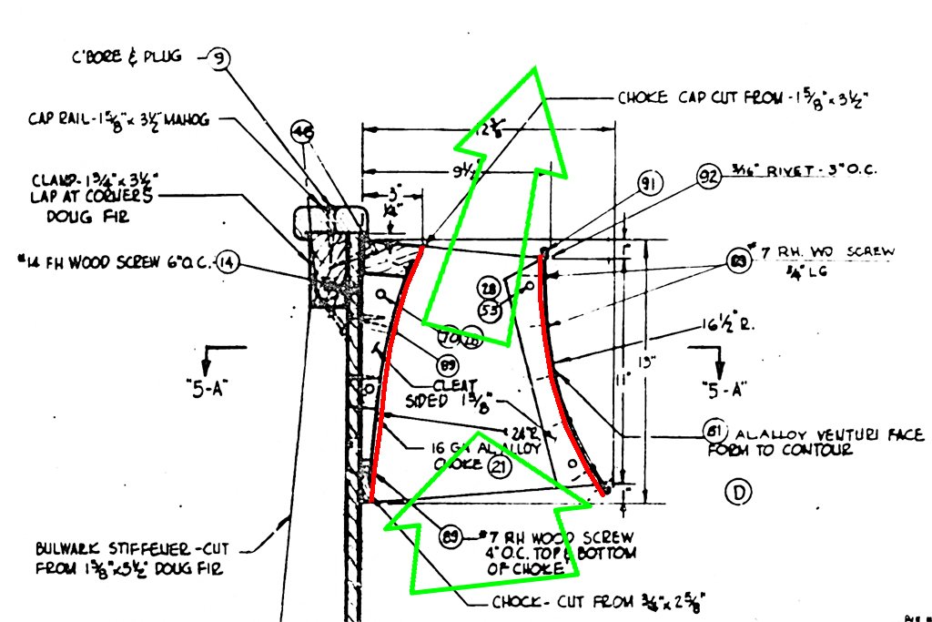
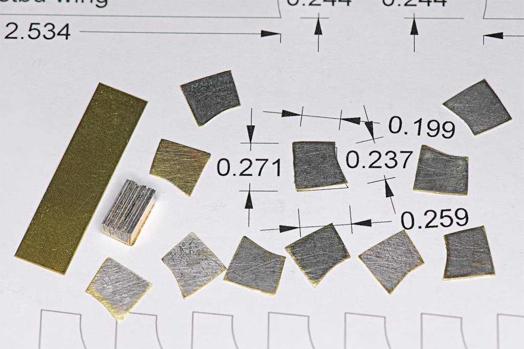
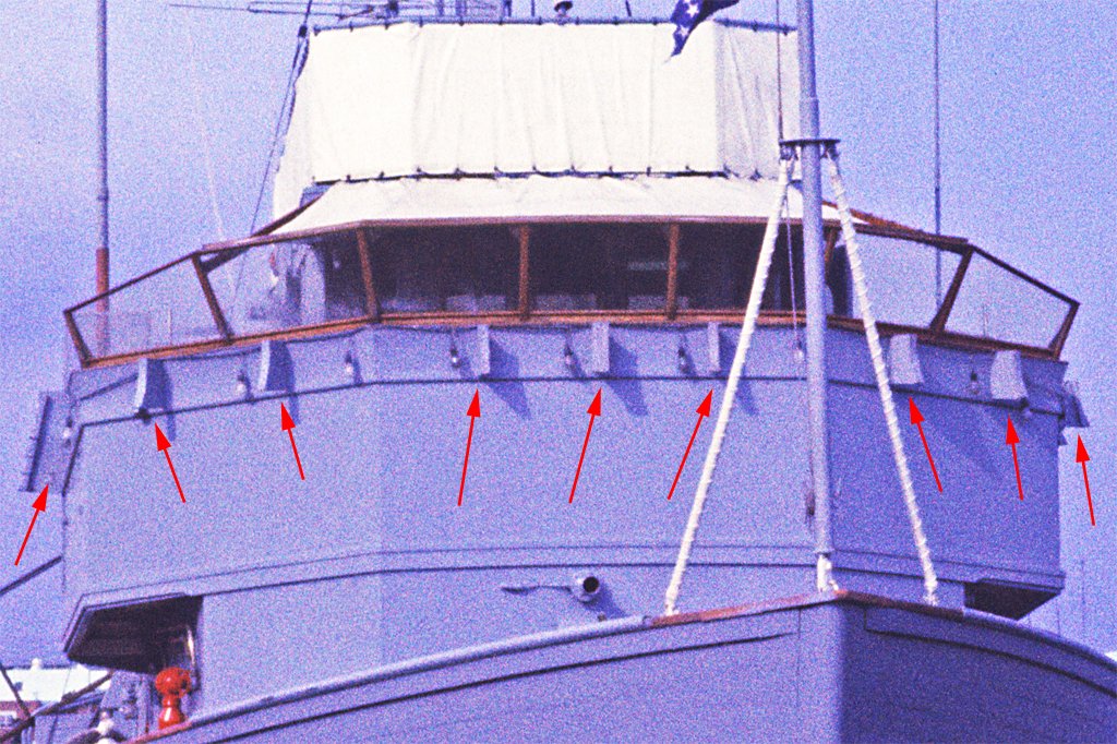
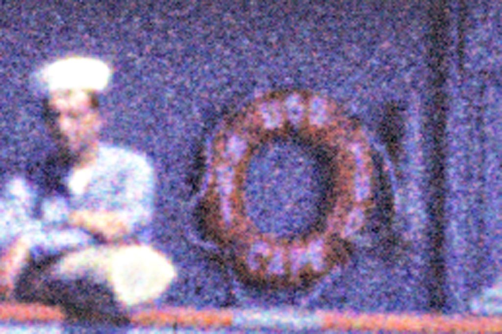
Venturis The Cape had venturis around the edges of the bulwarks on the open bridge. The supports are shown in the photo (left) while the venturis were being repaired. On the right you can see the venturi at the top outboard edge of the bridge bulwarks. The ship's name board is mounted on the venturi. What is a ship's venturi? It is a channel for air flow between two converging surfaces (marked in red). Air blowing against the sides of the ship's superstructure flows outward and upward along the deckhouse sides. It enters the bottom of the venturi at relatively slow speed (short and wide green arrow), and is compressed as the channel narrows. If you remember Boyle's Law (you did take physics, didn't you?) the initial pressure and volume equal the final pressure and volume P1V1 = P2V2 As the air flows through the venturi the volume decreases by about half, therefore the pressure doubles. This causes the air to flow faster to escape the top of the venturi. It comes out as a jet of air deflected upward around the sides of the bulwarks (long and narrow green arrow). Now you may be asking yourself "Who cares?" Well, that up flowing air collides with the wind coming from ahead and deflects it upward and over the bulwark. This actually does work, and has a significant effect. I have stood watch on the Cape's open bridge in a downpour. Standing back a few feet from the bulwark I was pelted by raindrops. But standing close up to the bulwark the jet from the venturi deflected oncoming wind and rain up over my head! Behind this invisible windshield the air was fairly calm. These things made standing watch on the open bridge a bit more pleasant. I have put off adding the venturis to the model for two reasons. First, they are on the outside of the wide bridge structure and subject to damage from handling while all the other work was being done. And second, I really had no idea how I was going to make them! The blueprint above shows that there is a "choke" piece attached to the bridge bulwark that forms the inner surface of the venturi channel. It was made from an assortment of wooden and metal pieces, but I decided to simplify it for the model. I shaped a strip of wood with a triangular cross section for this inner part. I tried to cut a concave surface into the face of it. First I made a scraper with the cross section pattern and tried to use it to remove wood. That was a failure - the basswood strip didn't cooperate with the scraper. Then I found a small bottle with a 1 inch diameter (25.4 mm) and wrapped it with sandpaper. This did work better than the scraper but the results weren't very consistent over the length of the strip. And after I was finished the curvature was so slight it really isn't noticeable! But the shape of the strip was good enough since it will be hidden inside the venturi anyway! To make the spacers that support the outer surface of the venturi (to be made of 0.005 inch/0.13 mm brass sheet) I cut some strips (left side of the photo) of 0.010 inch (0.25 mm) brass to a width slightly larger than the vertical dimension of the parts (0.271 inch/6.9 mm). These were sliced into short pieces 0.33 inch (8.4 mm) long, longer than the 0.259 inch (6.6 mm) length of the supports. Fifteen of these pieces were clamped together and soldered to make a single solid piece to work with. A paper template was glued to the side of the work piece and the block was filed to the correct shape. Then the spacers were sawed off the end of the soldered block. The remainder of the block can be seen on the left side of the photo - the multiple layers are readily visible. The block of spacers was reheated to melt the solder and free the individual parts. The wooden choke strip was cut into sections to fit between the individual spacers. These wooden pieces were glued to the bulwarks with Titebond Original cement. As each section was placed a brass spacer was glued to the end with Locktite Super Glue Gel. This allowed enough time to position the spacer correctly, and produced a very strong attachment. I have been dreading this assembly because it just looked like it would be so easy to break off one part while placing another. But it has been very sturdy and I have had no problems so far. I still have a bit of sanding, filing and filling on the wooden choke pieces to prepare for sealing and painting. And notice that I did repaint the life rings in proper Cape fashion!
- 465 replies
-
- 11
-
-

-
- minesweeper
- Cape
- (and 1 more)
-
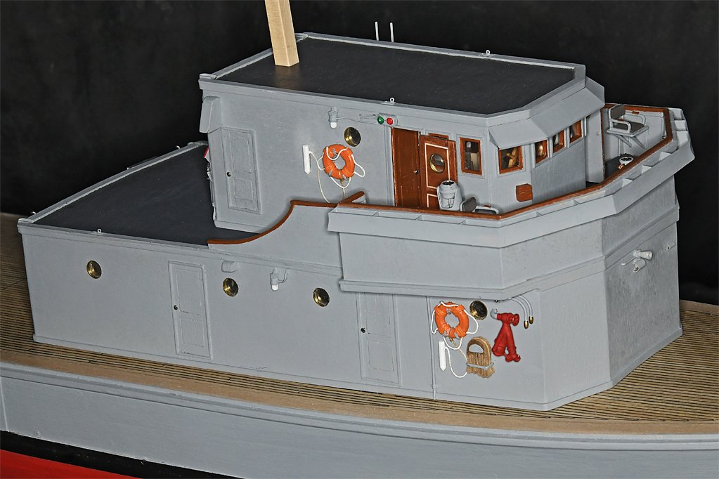
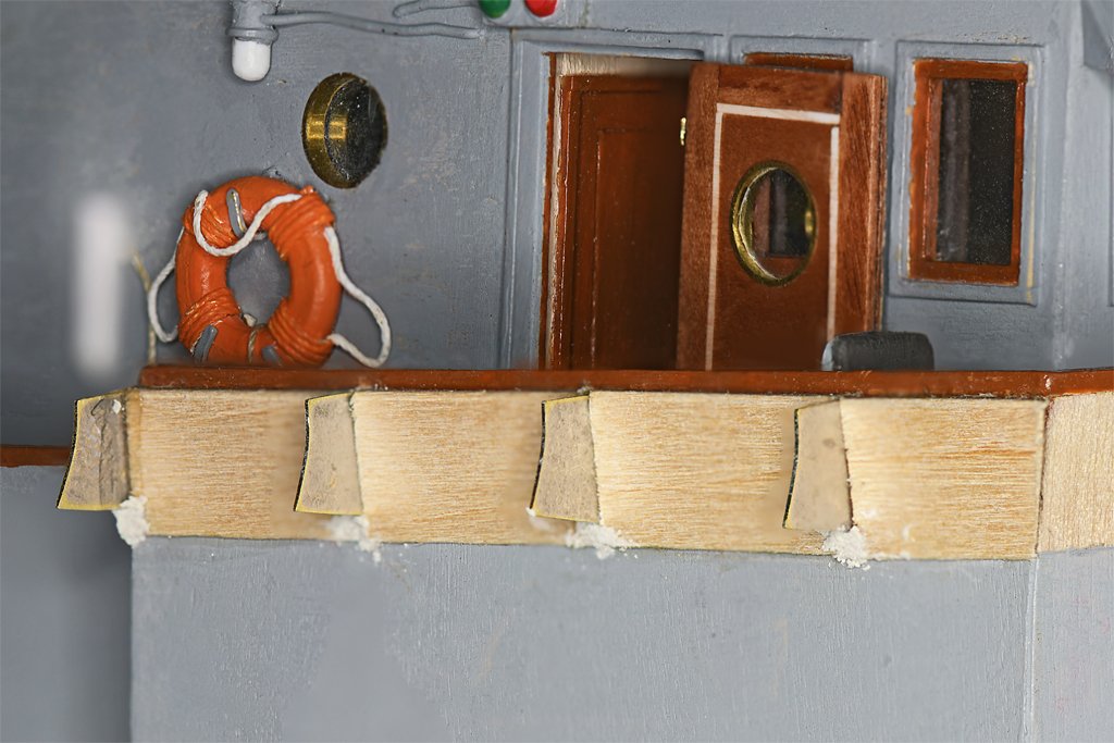
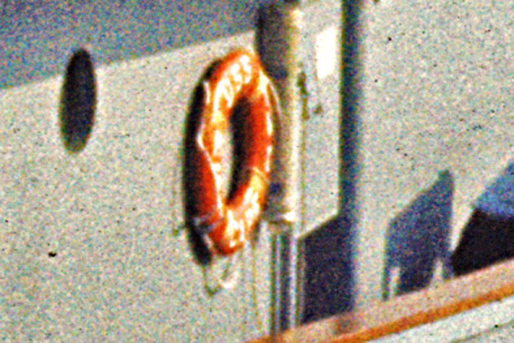
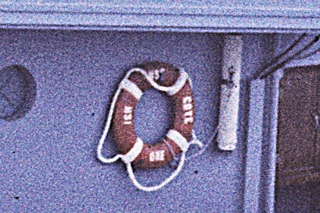
Roel, Your question made me do a double check on the life rings, and that brought a surprise! As you can see in this photo life rings were sometimes made up as I have modeled them. But if you look closely you will see this ring is labeled "USS COVE MSI ONE." This was the Cape's sister ship (possibly the actual smallest ship in the Navy). I have been using photos of both ships for determining how to build the Cape model. And I remember that I found the life rings were made up this way on the USS Oklahoma City CLG-5 when I made the CAD model of that ship. However, when I looked at the photo in post #420 above I realized that the life rings on the Cape were painted differently. The turns around the life ring were painted orange! I'll have to correct that! Although the Cove and Cape were very much alike, there were many small differences like this between the two. This was especially true in the way the crews painted the details like this. But there were also some structural differences, such as the Cove having 12 inch (305 mm) searchlights on the O1 level open bridge and the Cape having them above on the O2 level. The ladder on the port side of the O1 superstructure was a bit farther aft on the Cape. And the O2 level life rails and lines were a bit different. Thanks for keeping me on track! And I hope everyone had a happy day. It was Thanksgiving in the US and I am stuffed more than the turkey!
- 465 replies
-
- 6
-
-
- minesweeper
- Cape
- (and 1 more)