
HOLIDAY DONATION DRIVE - SUPPORT MSW - DO YOUR PART TO KEEP THIS GREAT FORUM GOING! (89 donations so far out of 49,000 members - C'mon guys!)
×


Dr PR
-
Posts
2,444 -
Joined
-
Last visited
Content Type
Profiles
Forums
Gallery
Events
Everything posted by Dr PR
-
 Roel, I don't know if any Navy manuals said to wrap ropes like shown here, but we had it on both the Cape and Oklahoma City. I suspect it was a bosun's thing - they killed time by applying small stuff around life rails, stanchions, ladder rails and just about everything else that didn't move. Fancy knots, braiding and such were normal. For example, here sailors are removing horizontal threads from a sheet of canvas. The vertical threads will be bunched together and braided to make "McNamara's Lace." It was a decoration that was hung around the quarter deck in port and on other things to make them look fancy. The braiding around hand rails and stanchions actually served a purpose. It made it easier to grip, especially if things were wet.
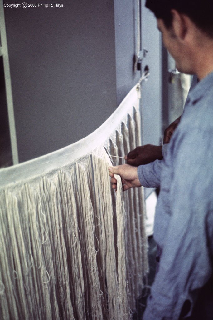
- 465 replies
-
- 7
-

-

-
- minesweeper
- Cape
- (and 1 more)
-
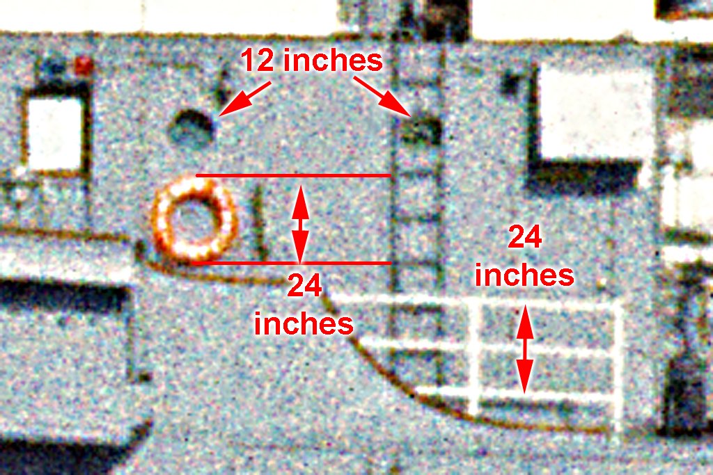
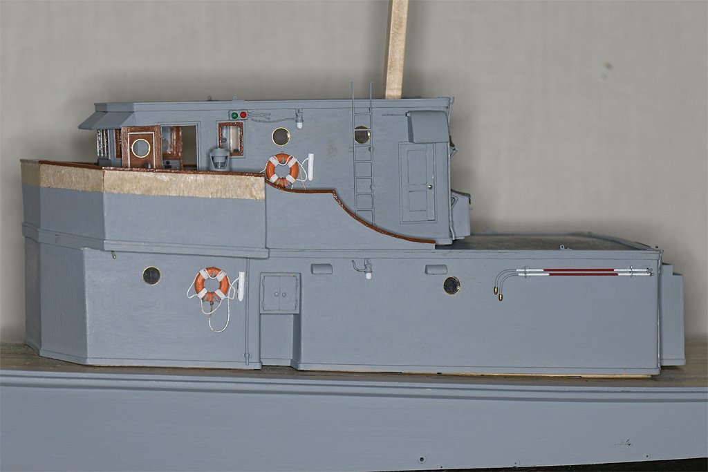
Thanks to everyone for the compliments. Bill, I wondered about the dimensions. The US Coast Guard uses 30 inch (762 mm) diameter rings with an 18 inch (457 mm) interior opening. We had 24 inch (610 mm) outside diameter life rings on the USS Oklahoma City CLG-5. The inside diameter was 13 inches (330 mm). It would be easier to squeeze into the larger life rings! I used photoguestimation to determine the diameter of the life rings on the Cape as shown in this photo. The port O1 level had air ports, a ladder and some life rails close to the life ring. The blueprints show how the ladders were made, with 12 inch (305 mm) spacing between the rungs. The top three pipes of the life rails were also spaced 12 inches (this was standard for the US Navy in the post WWII period). The air ports were 12 inches diameter. This rather grainy Extachrome 400 side-on photo of the Cape shows all of these features, and it is clear the life rings were 24 inch diameter. Just about any photo of a US Navy ship will show life rails, and these are a good "ruler" for measurement. You just have to be careful about perspective distortion in photos. However, there really was no standard spacing for ladder rungs on US Navy ships. Often the blueprints show the position of the top ladder rung (about 6 inches/150 mm below the upper deck level) and bottom rung (about 12-15 inches/305-380 mm above the lower deck). Then it shows some number of rungs between the top and bottom with "Equal" spacing. This usually came out between 11-13 inches (280-330 mm) between rungs. But the blueprints say all the vertical ladders on the Cape had 12 inch spacing between rungs.
- 465 replies
-
- 3
-
-
- minesweeper
- Cape
- (and 1 more)
-
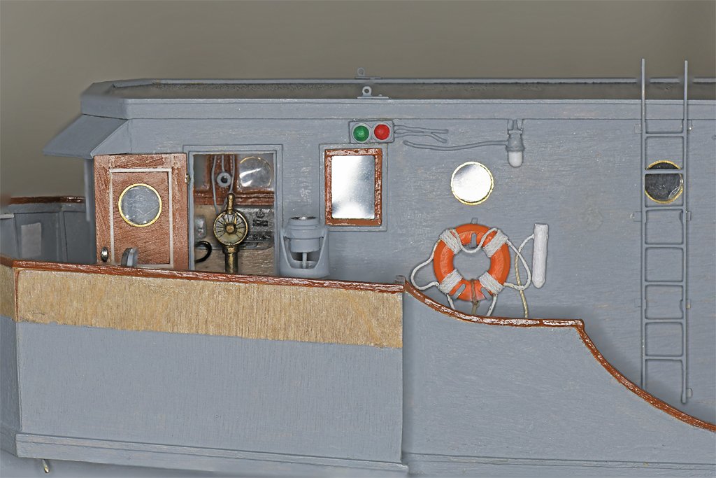
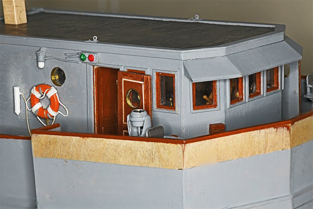
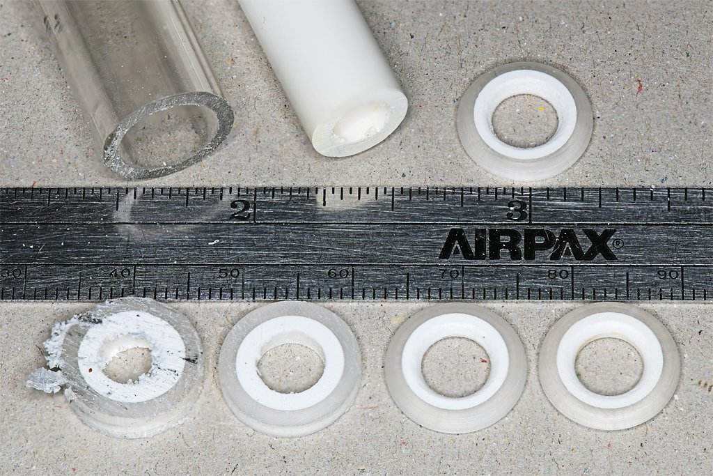
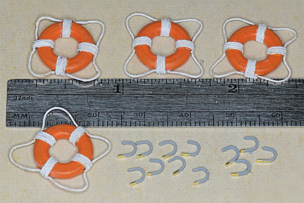
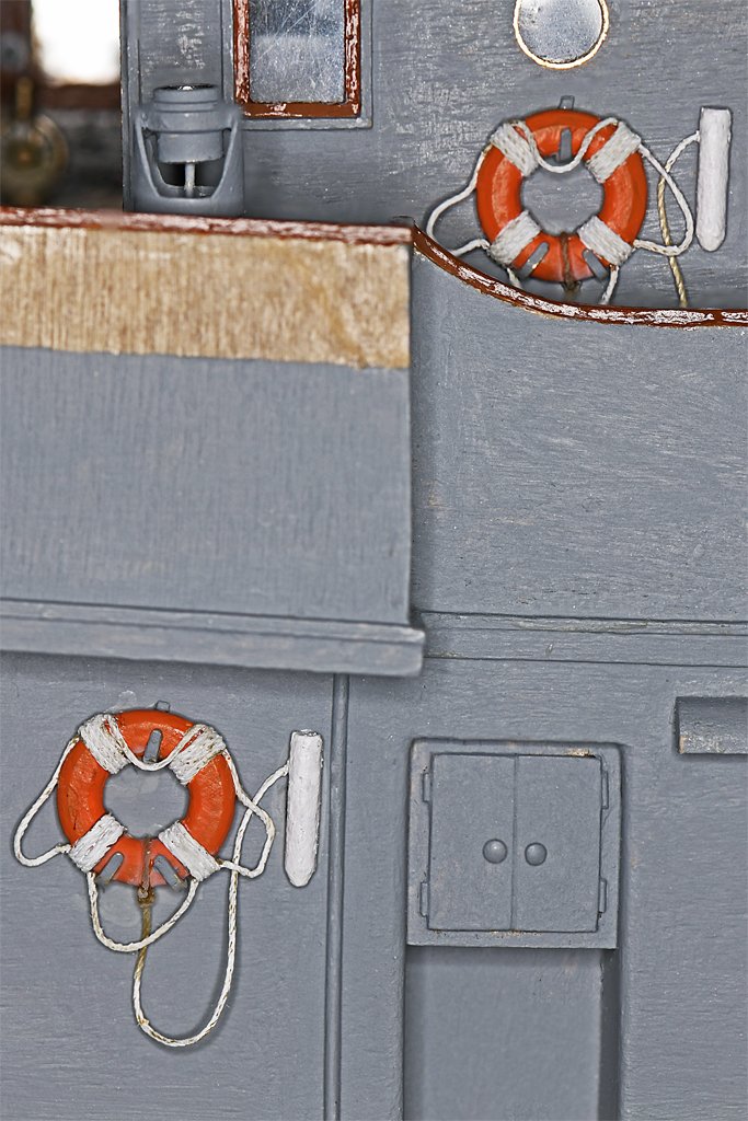
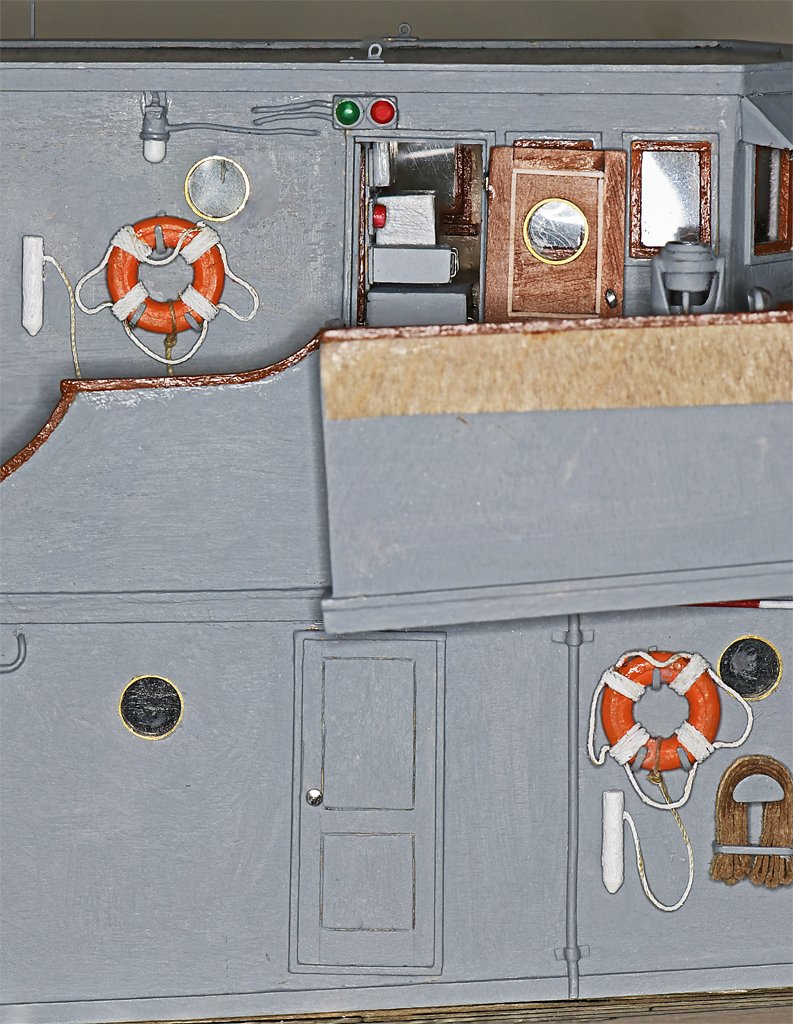
Keith, The explosions behind you aren't your concern. You want to watch for things in front of you that might blow you out of the water! Here are some more details. This time it is the life rings. The life rings were 24 inch diameter, and that comes out to half an inch (12.7 mm) at 1:48 scale. I looked through all the materials I have on hand and I could cut them from some 3/8 inch thick boxwood, or from some basswood sheets. But cutting from wood created the distinct possibility that it would break along the grain during the shaping process. It would be easier to cut them from a half inch dowel, but I didn't have any in stock. The only thing that diameter was some clear acrylic (Plexiglas) tubing. However, the walls weren't thick enough. But I did have some white styrene tubing that was a tight press fit into the acrylic and had an inside diameter a bit smaller (0.25 inch/6.35 mm) than the inside diameter of the life rings. Acrylic and styrene are easy to work, so I decided to use that combination. I sawed slices off the end of the concentric tubes and then filed/sanded them into the right thickness (0.073 inch/1.85 mm). I fit these rings over a 1/4 inch brass tube chucked into a drill and used files to round the outer edges. Then a combination of tools were used to round the inside edges and bring the opening up to the desired 0.275 inch/7 mm diameter. After they were painted orange I wrapped some carpet thread to make the ropes. Then three "J" hooks were made for each to attach them to the deck house sides. The white cylinders beside the rings are light floats. When they are positioned with the flat base upward the lights are disabled. In the water the flat base is heavier (batteries) than the top so it floats with the conical light on top and the light is turned on. The light makes it easier to find the life ring in the dark. I have added the pilot house doors and some other details. On the real ship the life rings were painted with "USS" in the top quadrant, "CAPE" on the bottom. "MSI" marked vertically on the left side and "TWO" vertically on the right. These letters would be only 0.010 to 0.015 inch (0.25 to 0.38 mm) high at 1:48 scale so I decided to not try to make them. Here is a close up of the port bridge wing with the pilot house door, pelorus, life ring and ladder to the O2 level installed. This completes the open bridge and pilot house side details. I guess the next work will be the venturis along the top of the bridge bulwarks and the port and starboard side lights. I still haven't decided how to make the venturis. I might work on some other details on the aft end of the O1 level, including the funnel. I also need to add the life rails around the O2 level and on the after end of the O1 level. And there are the windows and awnings on the front of the bridge bulwarks. All of these will be very delicate and will be saved for the last work on the deck houses. Here are a couple more photos of the open bridge and pilot house.
- 465 replies
-
- 14
-
-

-
- minesweeper
- Cape
- (and 1 more)
-
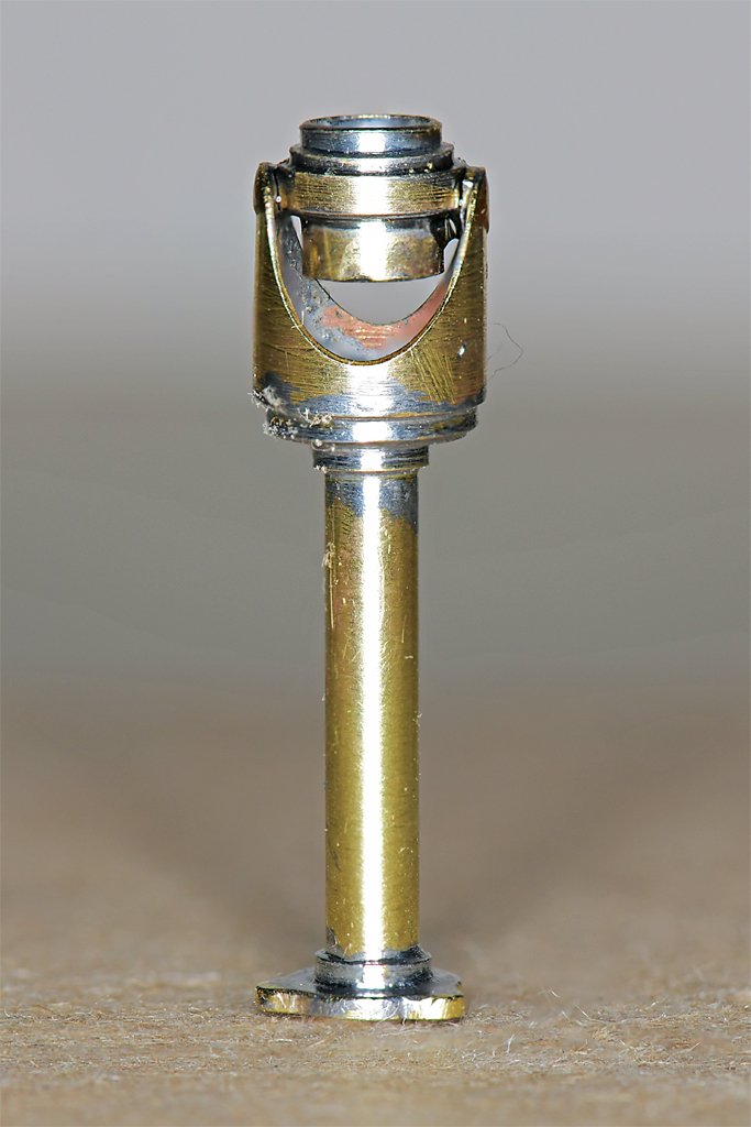
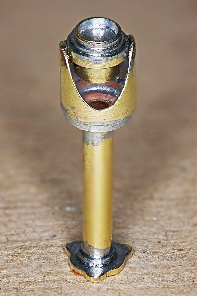
I was looking at the photo in post #389 and realized that I had cut the opening in the outer shell more of a "V" shape, and it should have been a wider "U" shape. I modified both units a bit, but still perhaps not wide enough at the bottom of the cut. I also realized I had forgotten to add the cable from the gyro repeater down into the base. The repeater was glued into the shell with super glue, so I just had to soak it in acetone to separate the parts. Looks like I got the repeater in the right hand part a bit misaligned when I glued it into place. I don't know if I will fix it. After it is in place on the model it won't be as noticeable as in this close up photo. (Note: I did fix it so the parts are aligned correctly.)
- 465 replies
-
- 11
-
-
-
- minesweeper
- Cape
- (and 1 more)
-
What are the fake gun ports made of? Epoxy is probably the all around best general purpose glue. It will glue just about anything to anything. I have used everything from very thin epoxy paint that soaks into wood grain to epoxy putty that is very good for molding parts, and it can be machined. The catch is the cure time. After mixing the two parts (be CERTAIN to follow the instructions) you have a limited time before the glue hardens. On the one hand some mixes set up in just 5 minutes, and some types take up to an hour to harden. So pick a type that gives you enough time to work with it to get things aligned, or to work with multiple assemblies, but not longer that you need. Once cured it is extremely difficult to remove. Rubbing alcohol will clean up excess before it cures. Super glues (CA or cyanoacrylate) are good for bonding metal to metal, and are commonly used for wood. Oddly enough, a web page describing many types of cyanoacrylate glues says it really isn't very good for wood! I have used it to glue metal to wood. The less you use the faster it cures. There are accelerators to speed up curing (although it is almost instant curing on metals and skin) and you can loosen it with acetone. CA gels are slower curing and give you a few seconds to position parts. But cyanoacrylates will fog most clear plastics and they leave a film on wood surfaces that interferes with staining. Use acetone to clean up residue.
-
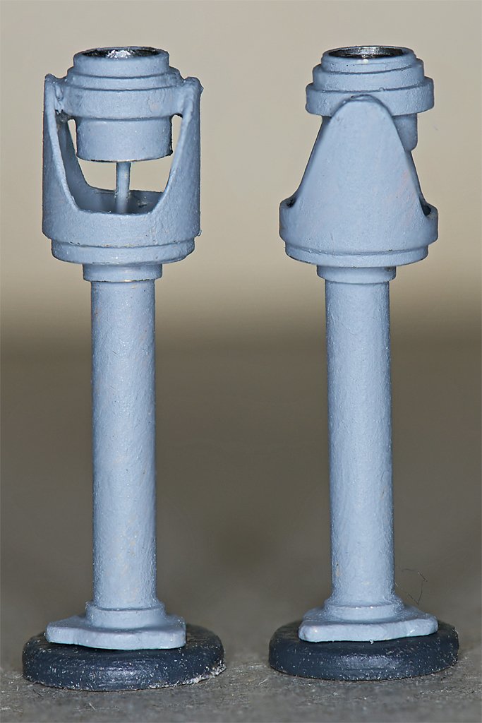
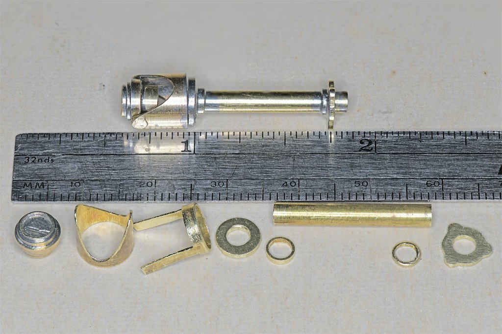
Here are one assembled pelorus and parts for a second. The gyro repeater is already assembled from three pieces of concentric brass tubing from 0.186 to 0.250 inch (4.7 to 6.4 mm) diameter. The center piece is a 0.154 inch (3.9 mm) brass rod. The other parts are made from brass tubing from 0.125 inch to 0.311 inch (3.2 to 7.9 mm) diameter and brass plate 0.030 inch (0.76 mm) thick. The trick with any part like this with many pieces that are to be soldered together is to figure out a soldering sequence so that when adding another part an existing solder joint doesn't melt and let the thing fall apart. The gyro head was assembled separately, and then the stand was soldered together from the top down. It just needs a good brushing with a steel wire brush and a coat of paint. Grey, of course! Then I'll glue a compass rose into the top of the repeater.
- 465 replies
-
- 13
-
-
-
- minesweeper
- Cape
- (and 1 more)
-
John, I did screw up the first one. I soldered the upper parts on rotated 90 degrees from what they should be! Instead of facing forward it faced inboard!! It was a long day. Not much more to report. I am working on parts for the peloruses. But I had to post some pictures for Keith showing how two-legged chairs work!
- 465 replies
-
- 10
-
-
-
- minesweeper
- Cape
- (and 1 more)
-
Keith, With the Cape's $1200US per year operating budget we couldn't afford all four legs. But two legs worked OK in McHale's navy!
- 465 replies
-
- 1
-
-
- minesweeper
- Cape
- (and 1 more)
-
I agree that the crossjack yard is usually the spar on the mizzen mast that spreads the clews of a topsail. The spreader yard on a schooner's square sail mast is often called a crossjack because it is essentially the same as the mizzen's crossjack on a square rigger. I read somewhere that whether the yard that the course attaches to is called a spreader or a course yard depends upon how much tackle is permanently attached to the yard. If it is fully rigged for a square sail, like the fore/main course yards on square riggers, it is called a course yard. If the spar is rigged only to spread the topsail it is a spread yard, but some rigging could be attached temporarily to raise a course. And then there are the spreader yards that rest on and are tied to the bulwarks, with the course sheets running through blocks on the yard arms. But what about the Bentkick yard? It is actually called a boom, although it is essentially a yard and nothing like the boom on for-and-aft sails! It is a spreader yard attached to the clews of the course, but pulled down to the deck with a tackle attached to the center of the yard. And I would bet dollars to donuts that there were other variations on this theme that none of us have seen! **** Trevor, Underhill (Masting and Rigging) mentions that luff tackle and buntlines were often belayed on the same pin since they are both slack when the sail is set, and hauled on when the sail is reefed. Since the studding sails are set only when the other sails are fully deployed the lines could be belayed on almost any point carrying other lines for the associated square sail. However, I also suspect they might have been tied off to any handy point on the mast or tops. I keep watching for some explanation of how to belay stuns'l lines.
-
Congratulations! Stepping the mast is one of the milestone achievements in model making. It usually means the wood work on the hull is finished and you are about to become all tangled up in rigging and sails.
-
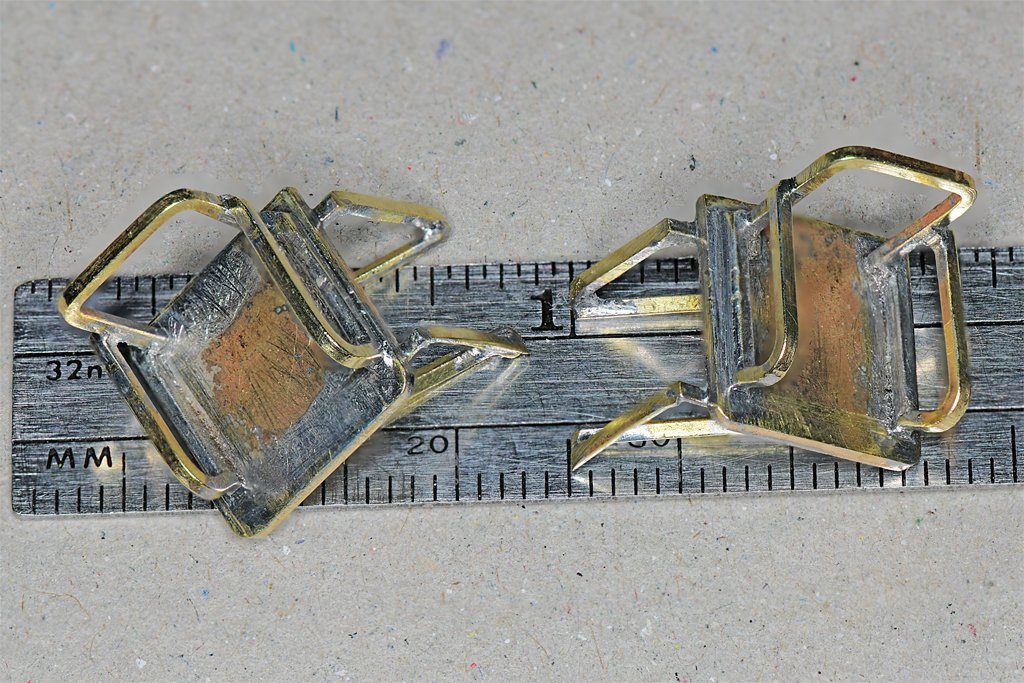
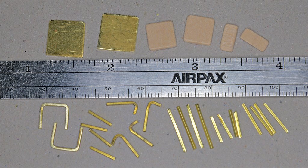
This is a kit of parts for two bridge wing chairs like you can see in the photo in post #389. I have one more photo that shows a chair from the front. From these I photoguestimated the dimensions. The bases were cut from 0.030 inch (0.76 mm) brass sheet. The arm rests and back pieces are 0.032 x 0.032 inch (0.8 x 0.8 mm) square brass rod. The seat support pieces are 0.032 x 0.032 inch brass "L". The square rod and "L" were made by Special Shapes Company (stock numbers S-1 and A-1). Unfortunately the company is no longer in business making these small parts and I have found no other company that makes parts this small. I bought these pieces about 15 years ago when a local hardware store closed. Here are the finished chair frames. The assembly was pretty tricky. It took about five hours to solder together the eleven brass pieces for the first chair. Working with such small pieces can be difficult - several parts popped out of tweezers and were never seen again. Just finding a collection of repositionable clamps to hold the parts in place while soldering is an adventure in itself. Getting enough heat sinks in place to prevent the heat from the current solder joint from flowing the short distance to another joint and unsoldering it is a challenge! Some of these joints were soldered up to five times to get everything in the correct positions. This is just good practice for the real challenges that will come when I start on all that complex minesweeping equipment on the stern. One thing I learned is that I need a lot more small heat sinks! The seats will mount to the bridge bulwarks with the triangular supports under the seat. They will be painted grey and wooden cushions and arm rests will be added.
- 465 replies
-
- 8
-
-
-
- minesweeper
- Cape
- (and 1 more)
-
Trevor, Wefalck told us in another post that Marquardt was German, and familiar with the northern European vessels and terminology. He later moved to Australia and wrote The Global Schooner - that could also account for some of his curious English terminology! I found his book very useful, but there were a lot of typos and other misinformation. You brought up a point in your post about stunsails. I have read that some of the rigging for stunsails was often left aloft. But I could find nothing about where the running ends were belayed. I examined the belaying plans for a couple of ships that used stunsails and found no mention of any of the stunsail rigging. Were the lines just belayed on the same pins as lines from the associated yards and sails? I know it was common to belay two lines on a single pin when the two lines had to be used together. Your comment about the work necessary for rigging stunsails reminded me of a comment I read somewhere that a sailor would look for evidence of stunsails on a ship (boom irons, etc.), and if it had them he wouldn't sign on.
-
Keith, Do they make dollhouses at 1:24 scale? If all else fails you might find a selection of furniture there.
-
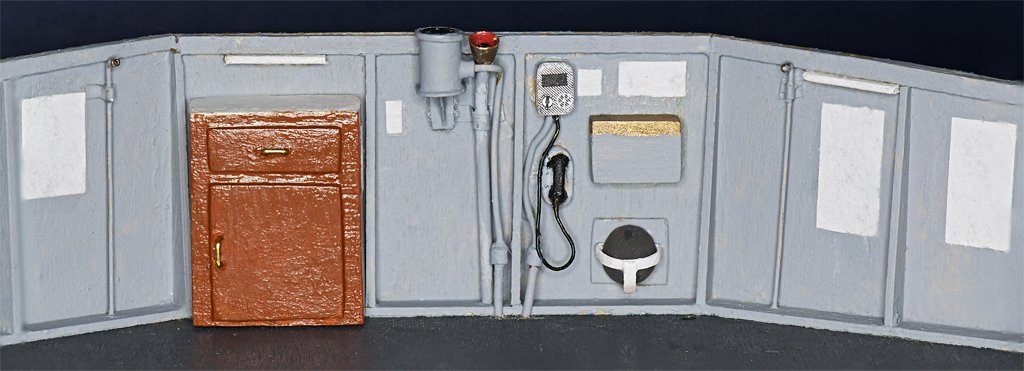
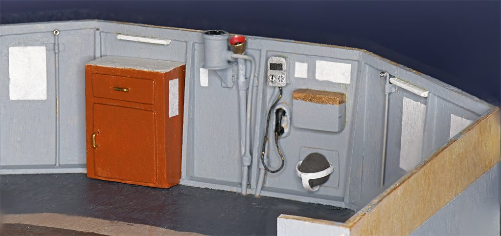
Keith, Thanks! Glad to see your Cangarda build underway again. John, The round thing is a weatherproof rotary switch. Only the top plate is round. The bottom part is octagonal - a standard US Navy switch box. And it all rests on a "D" shaped support. My guess is that it is a light switch. Minesweepers had a virtual Christmas tree of lights on the mast to signal all sorts of things from anchored, to sweeping moored mines (port and/or starboard), magnetic mine sweeps, acoustic mine sweeps, formation station, and such.
- 465 replies
-
- 4
-
-
- minesweeper
- Cape
- (and 1 more)
-
Roel, You have a good eye for detail! There is a rotary switch just aft of the pelorus on the bulkhead. A voice pipe - with a cap instead of a megaphone horn - is just aft of the switch. This went to the voice pipe on the navigator's desk, for use when taking bearings to objects to locate the ship's position. We didn't have a voice pipe to the engine room. We could just open a door or two and shout - it was a small ship. Actually, we used sound powered phones and the Engine Order Telegraph. I have looked through the blueprints (at least those I have digitized) and can't find reference to he switch. I'm sure it is listed somewhere in the several hundred pages of blueprints, but I don't know what it was for. It might have been added after the ship was built. There were several changes from the initial construction, and some of these are apparent when comparing the Cape and the Cove. The blueprints show a 12 inch (30.5 cm) searchlight just aft of the voice tube, and there is one at that position on the Cove (and another on the port wing). But the Cape had both searchlights on the O2 level where they would be more effective. One of the things I am doing as I build the model is trying to verify that things actually were where the blueprints show them.
- 465 replies
-
- 4
-
-
- minesweeper
- Cape
- (and 1 more)
-
John, Are you referring to the triangular light gray thing outboard of the cap rail close to Fred's elbow? I have puzzled over that also. It appears to be the corner of the venturi. The forward section of the venturi is bent inward like something had hit it, bending the outboard edge upward. I don't recall this happening. Because we got underway infrequently I can't imagine when this happened. The ship had just had the venturis replaced when I first went aboard, so it wasn't old damage. It wasn't a side light. Unlike every other ship I have seen, the Cape's side lights were tiny, like bicycle tail lights! Or like the wing tip lights on a small airplane. They were on the outboard side of the bridge bulwarks a bit below the cap rail.
- 465 replies
-
- 2
-
-
- minesweeper
- Cape
- (and 1 more)
-
Bruce, I like the fuzzy chenille bagywinkles/baggywrinkles better than the tight yarn versions. The mast is coming along fine.
-
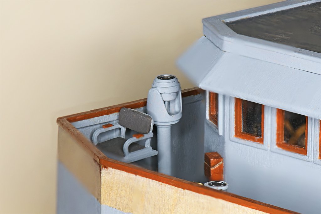
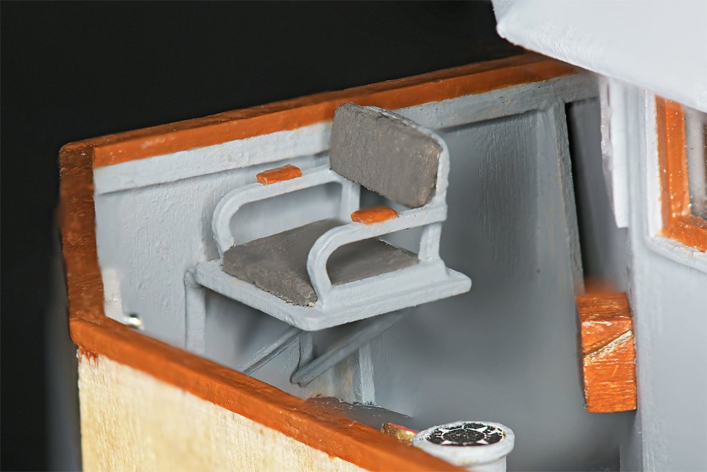
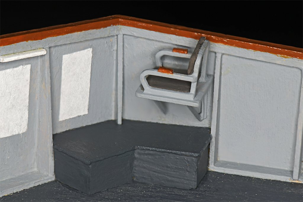
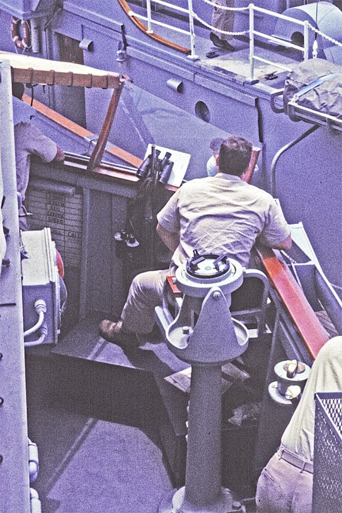
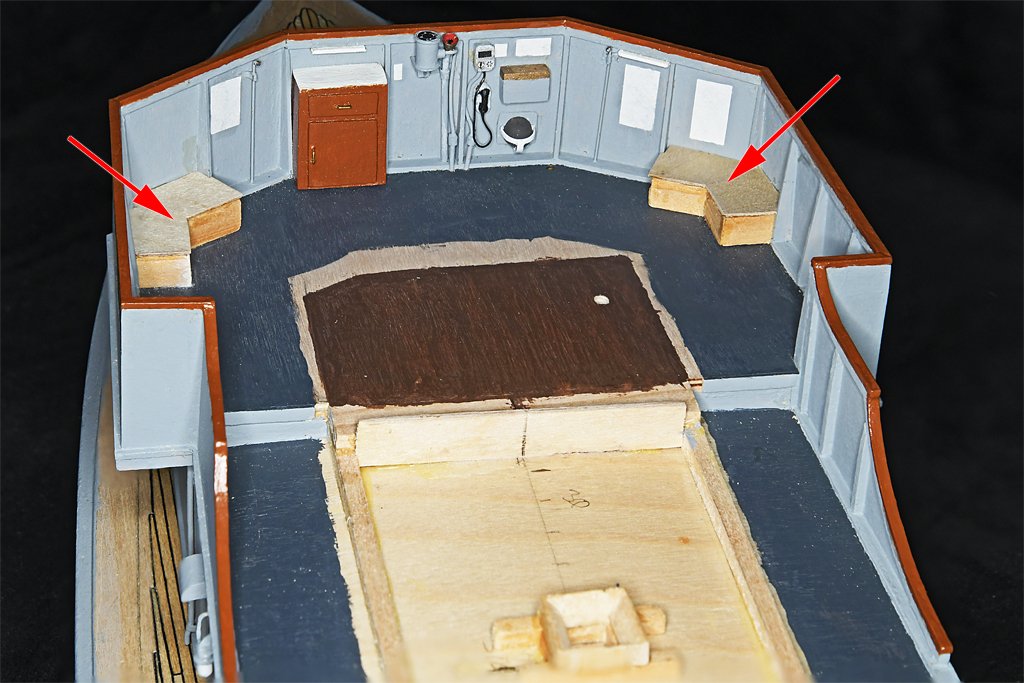
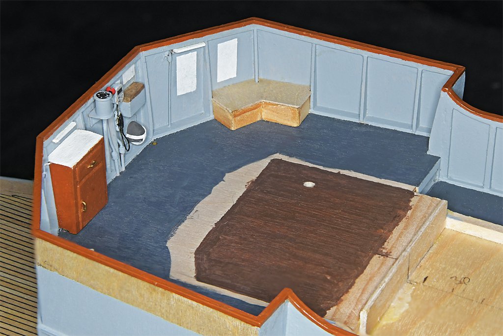
I have finished the bridge bulwark extensions along the O1 level. I added the mahogany cap rail - the blueprints say this piece actually was mahogany. The cap rail along the main deck bulwarks was supposed to be made of Douglas fir, although it was painted to look like mahogany on the ship. Next up were the bridge wing chairs and peloruses. I searched trough the pictures I had taken on the ship and found this photo. Here you see Captain Fred (SOPA - Senior Officer Present Afloat) taking the USS Cape MSI-2 going alongside the USS Cove MSI-1 on one of those occasions the rest of the mine squadron told us to "go away" (stay out of the way) until the end of the minesweeping practice. This was when we caught the shark (in an earlier post) and had a barbeque on the fantail. The picture shows a bit of the detail of the chair. It is enough to let me model something pretty accurate. It also shows the chair is anchored to the bulkhead, and is not resting on a pedestal. On the Oklahoma City the bridge chairs were larger, with a higher back, and swiveled on a pedestal. They were probably made of steel, and that wouldn't do on a minesweeper. The trick is determining the chair dimensions from just a photo like this. The blueprints do not show chairs on the bridge, but we had one on each side. But the blueprints to tell that the base of the pelorus was 17 inches (43.2 cm) diameter. It is close behind the chair so I can use that dimension to "photoguestimate" the width of the chair. The drawings also show the height of the pelorus and that will tell the approximate height of the chair parts. But this photo also revealed something else not in the blueprints, and it answers John's earlier question about the "tall bloke" on the bridge. The chair is positioned above a "V" shaped platform that follows the angle of the bulwarks. I have enhanced the brightness and contrast in the photo to reveal this platform. And it was this platform the tall bloke (Captain Buck) was standing on. From the photo I estimate the height of the platform was 1 foot (30.5 cm) and it was two feet wide (61 cm). It fits between the vertical bulwark supports, so I can determine the shape and dimensions pretty accurately. Here are a couple more pictures showing these platforms.
- 465 replies
-
- 9
-
-
-
- minesweeper
- Cape
- (and 1 more)
-
Basswood Strips
Dr PR replied to DGraley's topic in Building, Framing, Planking and plating a ships hull and deck
I bought some nice boxwood strips from Modeler's Sawmill in Rutherford New Jersey, USA. (modelerssawmill.com). Fast Tracks, Inc. (https://handlaidtrack.com)in Port Dover, Ontario, Canada sells Mt. Albert Scale Lumber wood strips of good quality. I ordered a lot of basswood strips from Sig Manufacturing. They were pretty good quality, but there was quite a bit of variation in the dimensions of the smaller strips. Other suppliers had better tolerances. Sig also has an excellent line of very thin plywood. Midwest Products (www.midwestproducts.com) has an excellent selection of small dimension basswood strips. Good tolerances. Bud Nosen Models (https://budnosenmodels.com/) has a good selection of wood strips and thin plywood. -
I looked at Michaels when I was making baggywinkles and they have dozens of types of knitting thread and yarns. I did find a heavy knitting yarn that looked like it would wind around a rope without becoming too compressed, but the roll was about 500 feet and cost 7-8 dollars. I only needed a couple inches. I used pipe cleaners I have had on the shelf for at least 30 years (I don't smoke so they are only occasionally used to clean out small tubes, etc. I don't know where you would find them today.
-
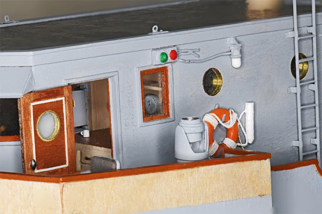
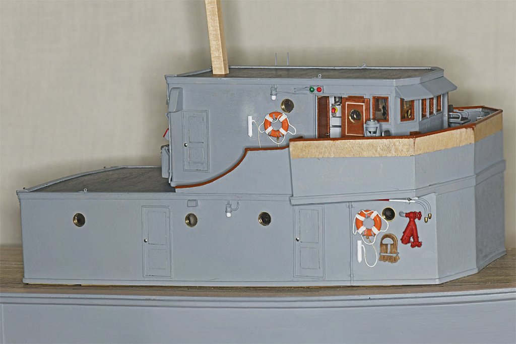
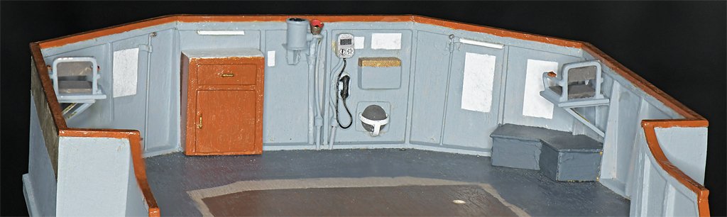
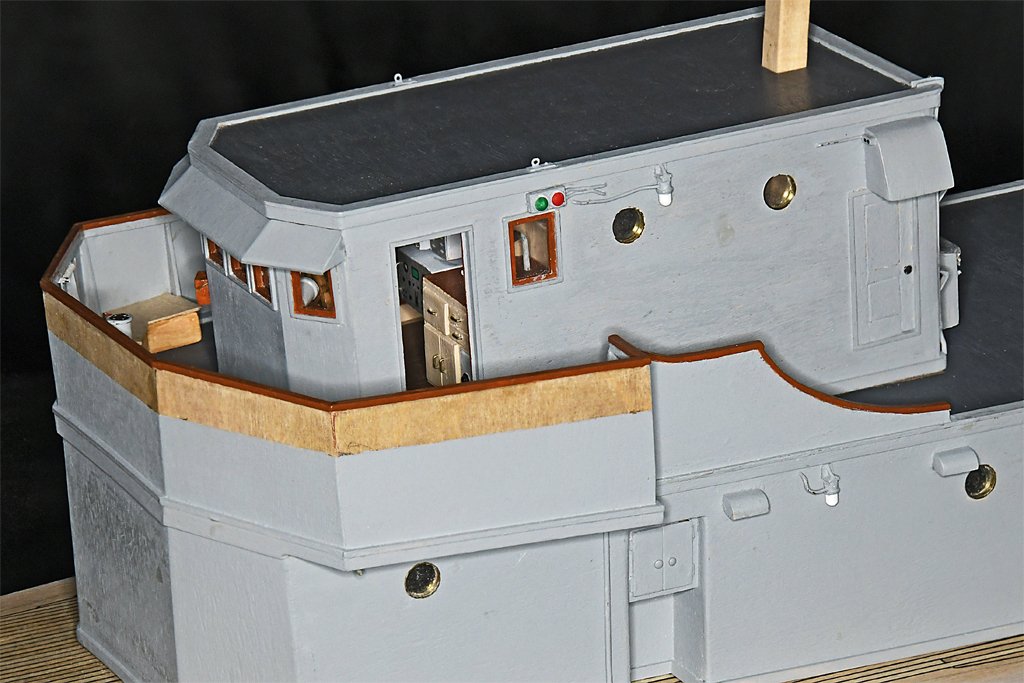
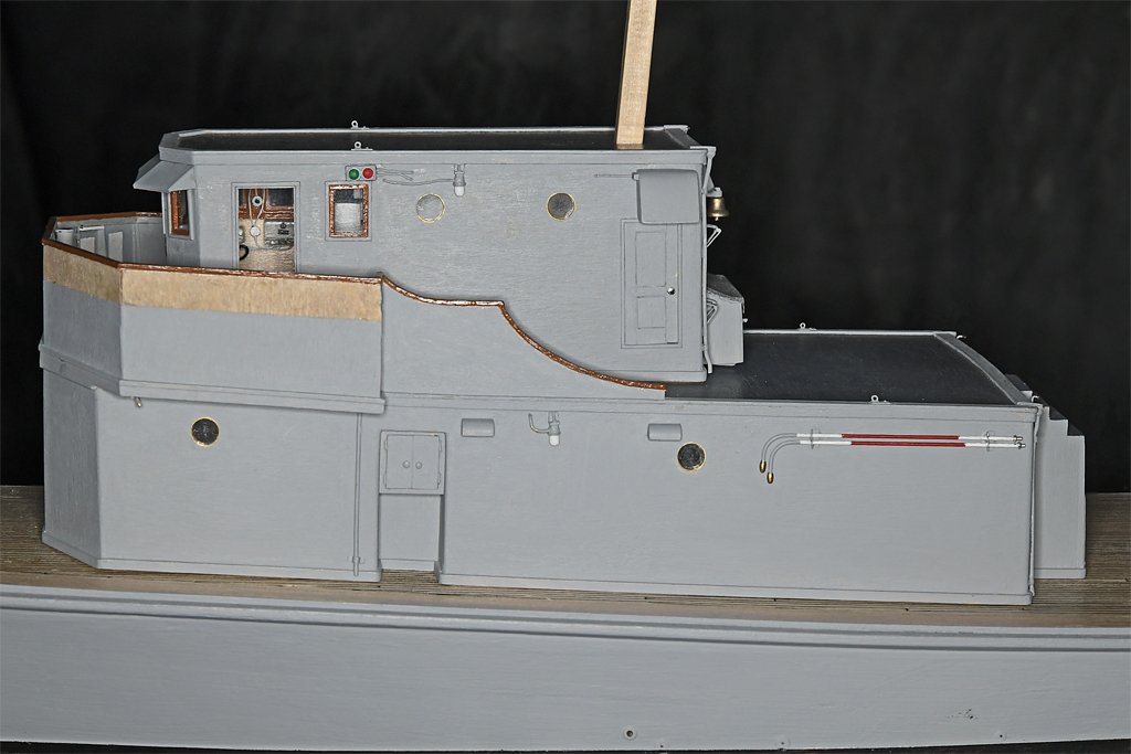
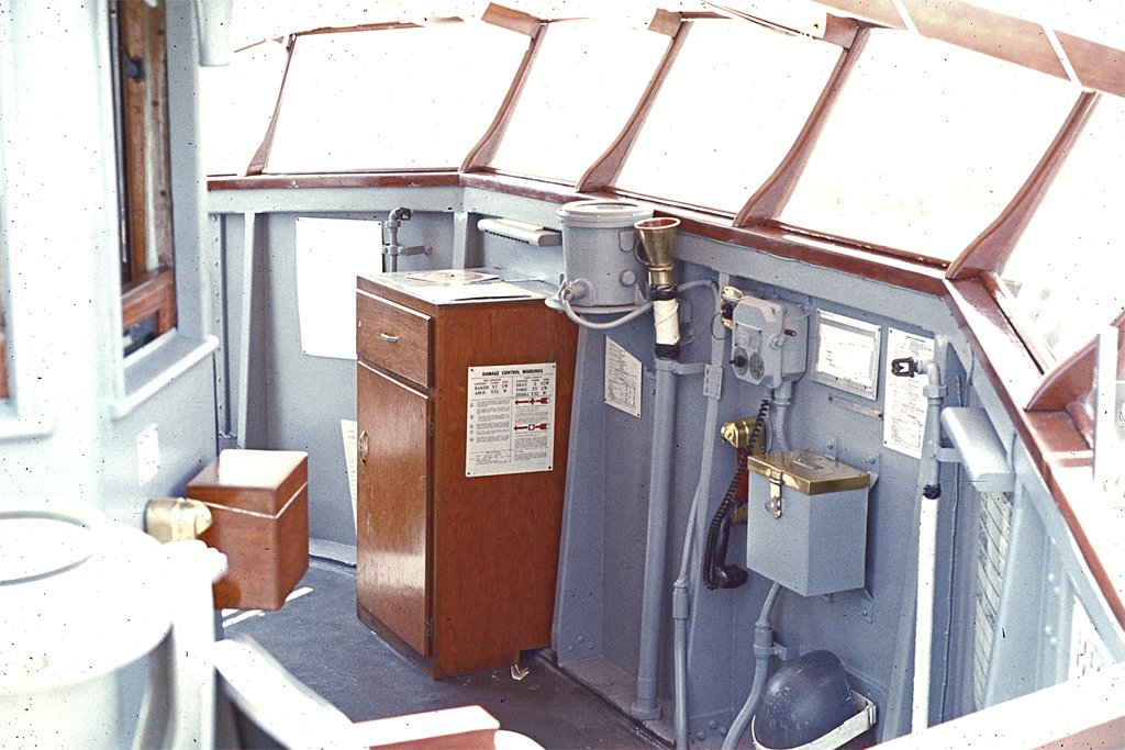
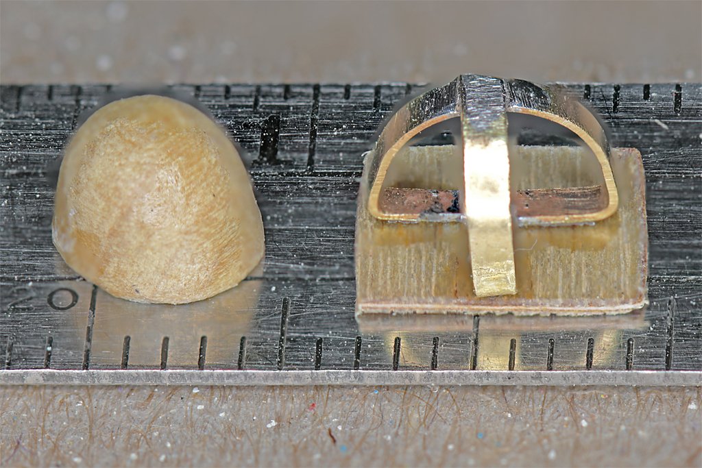
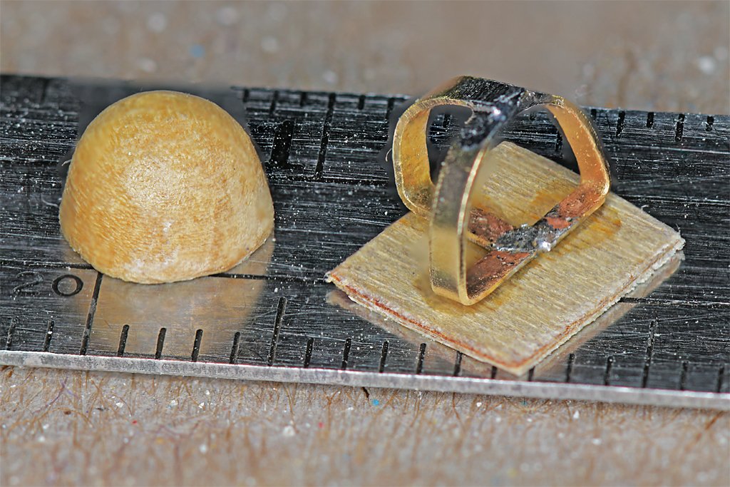
Here is a photo of the open bridge on the Cape. This was the normal conning station for driving the ship at sea. At the center is a gyro compass repeater and a voice tube to the helmsman in the pilot house. The windows on the bulwark and canvas awning overhead helped keep out the weather, but it could still be cold and wet in heavy seas. I have been working on the details on the bulwark. One of the details is the helmet stowage at the bottom right of the picture. The MSI blueprint set included drawings of these things. The helmet is a standard M1 steel helmet. I carved it out of boxwood. As I was doing this I was thinking it would be a lot easier to just find some cheap 1:48 or 1:50 plastic toy soldiers and chop off the head of one of them. The straps were actually made of woven cloth or canvas - I used 0.008 inch (0.2 mm) brass strips about 1/32 inch (0.8 mm) wide. If you look closely you will see that I didn't achieve perfect representation of what is shown in the photo. The voice tube moved to the left slightly as the glue hardened and I couldn't wrap the cable from the gyro repeater behind it as shown in the photo. And after I had glued the sound powered phone station in place I noticed that it should be a bit more to the right so a separate phone connection box could fit between it and the bulwark stiffener. This completes the inner bulwark detail. Now I need to work on the extensions of the bulwarks along the sides of the O1 level, and complete the details on the front of the deck house.
- 465 replies
-
- 14
-
-
-
- minesweeper
- Cape
- (and 1 more)
-
The forestay is twisting because it has strain on it. The scale ropes we use are made with a single direction turn - a spiral. When it is stretched the spiral partially unwinds, causing the free end of the rope to spin. Real heavy ropes were made with left hand right hand turn layers to counter this tendency to twist. You can reduce the twist by slacking the line a bit. You just need enough tension to pull the line straight. It shouldn't be trying to bend the mast. For the deadeyes and sheer poles I would loosely rig all of the deadeye lanyards first - don't tie off the end yet. This will hold the ends of the shrouds and deadeyes in place while you attach the sheer poles. Then finish tying off he lanyards.
-
I remember these things - when I was a kid I lived about 45 miles from Little Rock AFB where these were stationed. They were a beast to fly. About 22% of them crashed, mainly on take off.
-
Bullseyes & Lanyard - some help please.
Dr PR replied to Capt. Kelso's topic in Masting, rigging and sails
You need a copy of Darcy Lever's The Young Sea Officer's Sheet Anchor 1808 (Algrove Publishing Limited, Ottowa, Ontario, 2000). This was written for young sea officers to tell them how to rig and sail ships. It is a fascinating read and invaluable reference. On page 14 he describes bull's eyes as "a wooden thimble, with a hole in the enter, and a groove in the circumference." On page 24 he says three or more turns are taken through the eye and "stopped to the standing part or hitched around the stay." Of course, he tells in detail how to "stop" or "hitch" the line on pages 8 and 9. How do you raise a mast when you don't have a crane to lift it? Lever explains how! It is the most useful reference for sailing ship rigging that I have found! -
For the sails on my topsail schooner model I followed Tom Lauria's YouTube procedure in Making Sails for Ship Models From Silkspan. He shows a technique for folding silkspan sail material for furling the sail on the boom.
