HOLIDAY DONATION DRIVE - SUPPORT MSW - DO YOUR PART TO KEEP THIS GREAT FORUM GOING! (89 donations so far out of 49,000 members - C'mon guys!)
×


Dr PR
-
Posts
2,441 -
Joined
-
Last visited
Content Type
Profiles
Forums
Gallery
Events
Everything posted by Dr PR
-
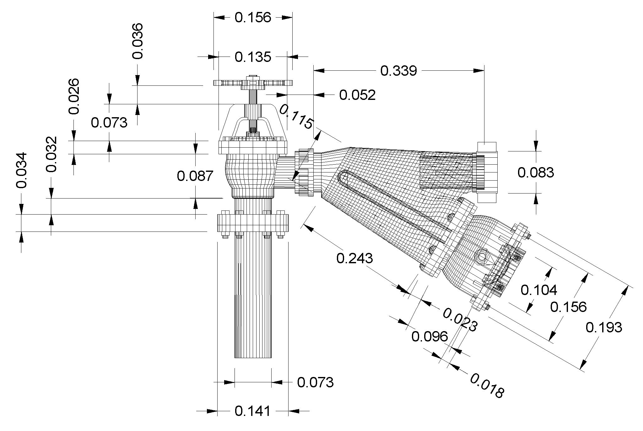
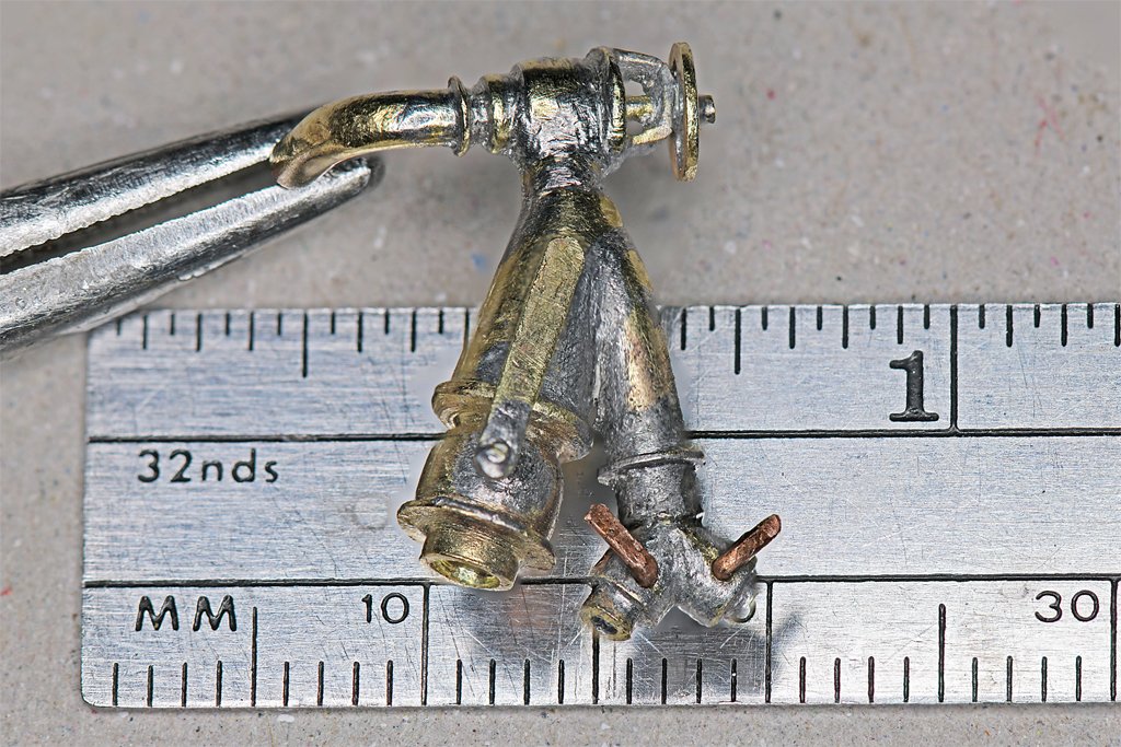
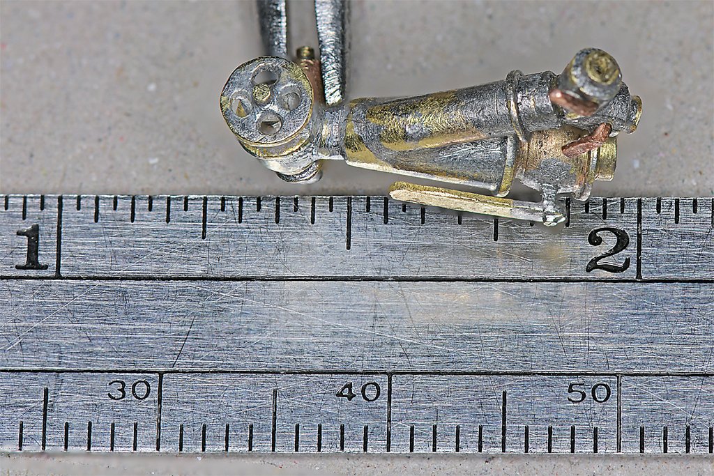
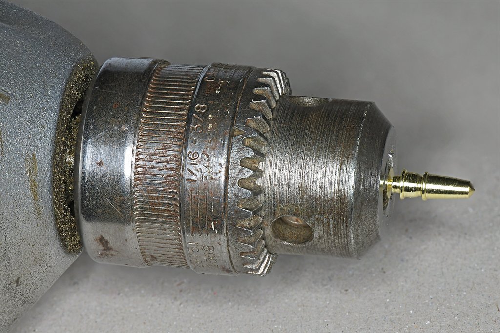
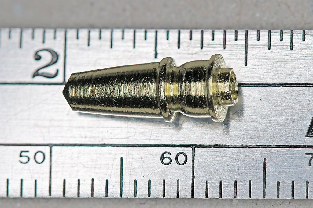
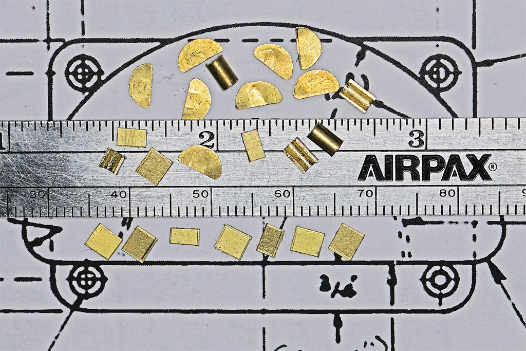
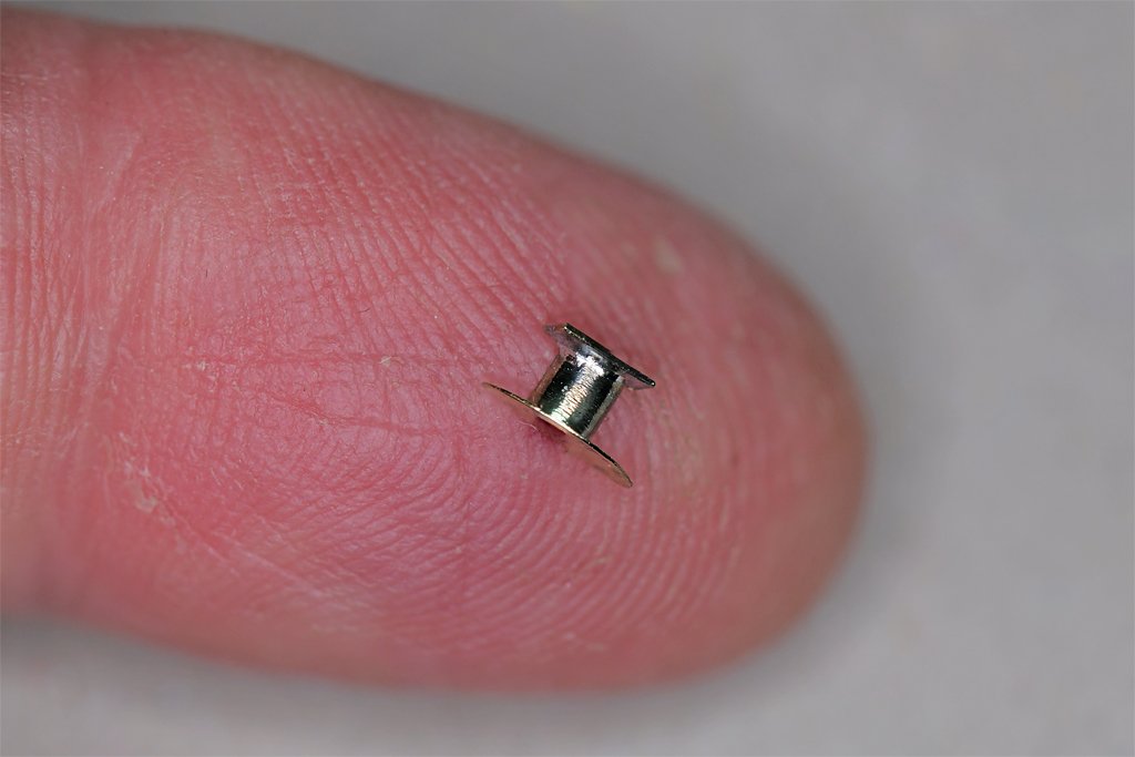
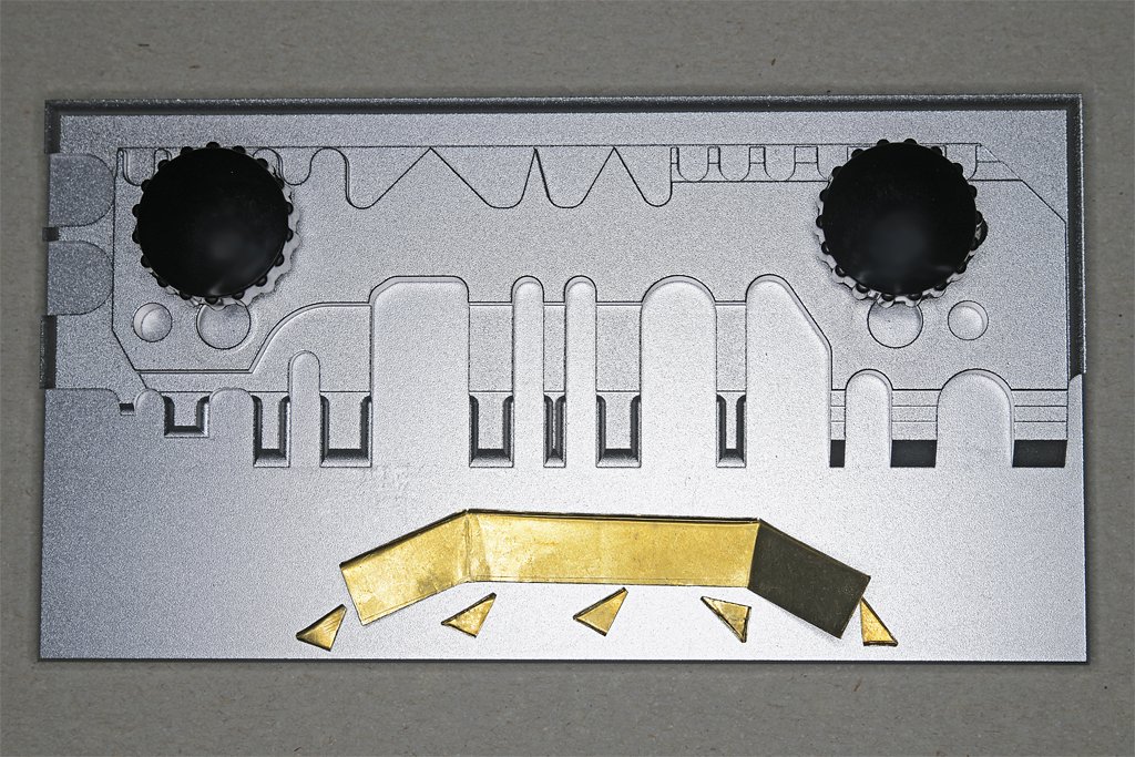
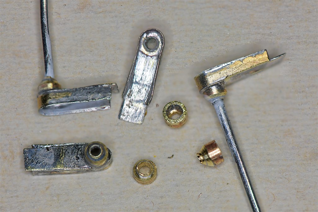
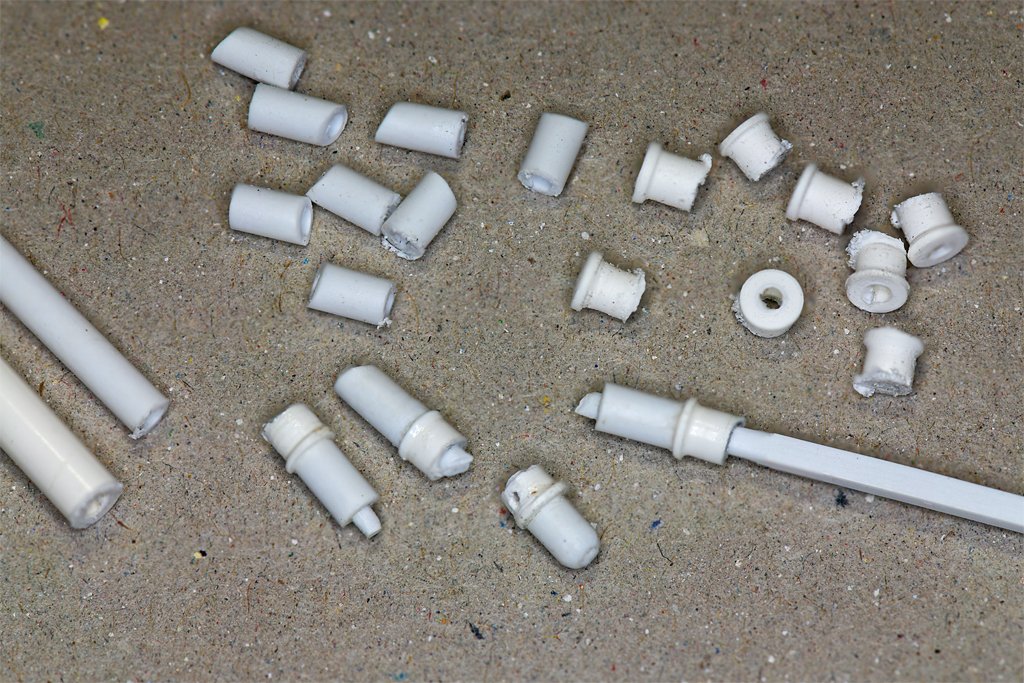
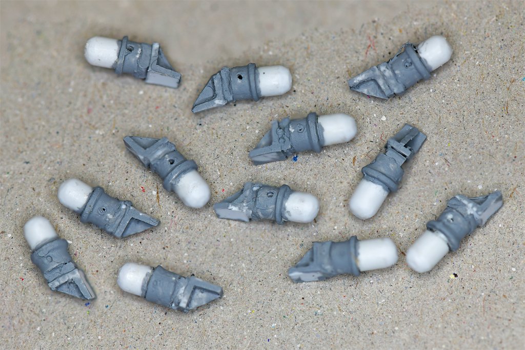
 The parts on the left are a "kit" to make one of these things (on the right). This is a 1:48 scale shipboard fire hydrant. I made the 3D model for my USS Oklahoma City 3D CAD model. I rescaled it to 1:48 for the Cape model and added a dual 1-1/2" hose attachment to the outlet as shown on the Cape blueprints. Once again this is pretty small stuff! I made all of the parts out of brass rod, tube and sheet. I count 22 individual pieces in all. At the top is a globe valve to shut off the flow of water. Then there is the larger strainer and collection part at lower right. Ships use sea water to fight fires, and barnacles and other marine growth form in the water intakes. This debris can clog the fire fighting nozzles, so a strainer diverts the garbage to the large collection part. The long handle opens a valve at the end of the strainer to flush out all of the debris onto the deck. The most difficult part was the conical strainer body. I thought about different ways to make it and decided to "machine" it out of a piece of 0.188 inch (4.8 mm) brass rod. While I was at it I decided to carve the globe valve discharge outlet and a couple of flanges from the same piece instead of trying to piece together multiple parts. I used my 3/8 inch (9.5 mm) "hand lathe" to make the part. This is an ancient 3/8 inch electric drill I purchased in 1972 after leaving the Navy. The bushings are shot but it is still useful as a poor man's lathe. This would have been a LOT easier with a real lathe!!!!! I used files and a thin curf saw blade to carve out the piece. You might think I was crazy to attempt to make this complex part using a hand drill instead of a real lathe. I would not disagree with that assessment! OK, I am crazy. But hey, it worked!! The rest of the assembly was made of 0.039 inch (1mm) brass rod, 0.0625 inch (1,6 mm), 0.091 inch (2,3 mm), and 0/125 inch (3,2 mm) brass tubing and 0.005 (0,127 mm), 0.010 (0,25 mm) and 0.015 inch (0,38 mm) brass sheet. I used an ordinary soldering iron and a resistance soldering station to assemble the parts. The resistance soldering tool has the advantage of focusing the heat in the places that the pieces fit together, and not heating the entire piece. Nevertheless, each of the 17 solder joints was reheated up to six times to allow the parts to be repositioned. This is the final assembly. It looks so good at arms length, and then I look at the macro photos and it looks like it was dredged up from the Titanic! This is the first finished assembly. Tomorrow I will make the second piece from the kit of pieces shown in the first photo. It took a day and a half to make this assembly, but that included making the parts for the second assembly. The second part should go faster. The entire thing was made by hand using a collection of drills and files to shape the brass.
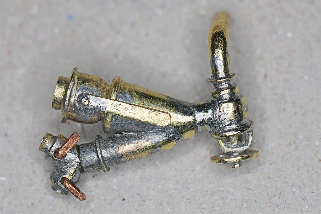

- 464 replies
-
- 17
-

-

-
- minesweeper
- Cape
- (and 1 more)
-
You definitely need to put the hoops on the mast before adding details in the tops. I assembled the mast on my schooner model with the hoops in place and the tops rigged. The boom and gaffs were laced to the sail off the mast, and then attached to the mast. Then I tied the gaff sails to the hoops. That was tight work! I think it would be better to assemble the gaff sails to the boom and gaff, and tie the hoops to the sail. Then you can slip the hoops over the mast and attach the boom and gaff to the mast.
-
Brass stock in small sections....?
Dr PR replied to Mark Pearse's topic in Metal Work, Soldering and Metal Fittings
Years ago I bought out the small brass stock from a hardware store that went out of business. Some of it was K & S, but the really tiny stuff was from Special Shapes company. I guess they went out of business or were bought by another company because the web site no longer exists. They made brass shapes like "L", "H", "T" in dimensions down to 1/32 inch (0.8 mm) plus rods down to 0.010 inch (0.25 mm) diameter. I don't know of anyone making this small brass stock now. -
I have used a acrylic sealer prior to painting wood with acrylic paints. I haven't noticed significant fuzz on basswood or boxwood. Of course, the purpose of the sealer is to fill and tiny cracks or grain, and it is always sanded afterwards to ensure a smooth surface for painting. FolkArt all-purpose sealer, satin finish
-
John, I think I will use thin cardboard for the hoses. It should fold easily and the somewhat fuzzy surface will resemble the hoses. Steve, Most of it will be hidden by the hoses.
- 464 replies
-
- 5
-
-
-
- minesweeper
- Cape
- (and 1 more)
-
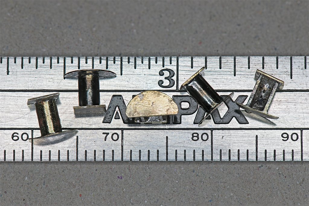
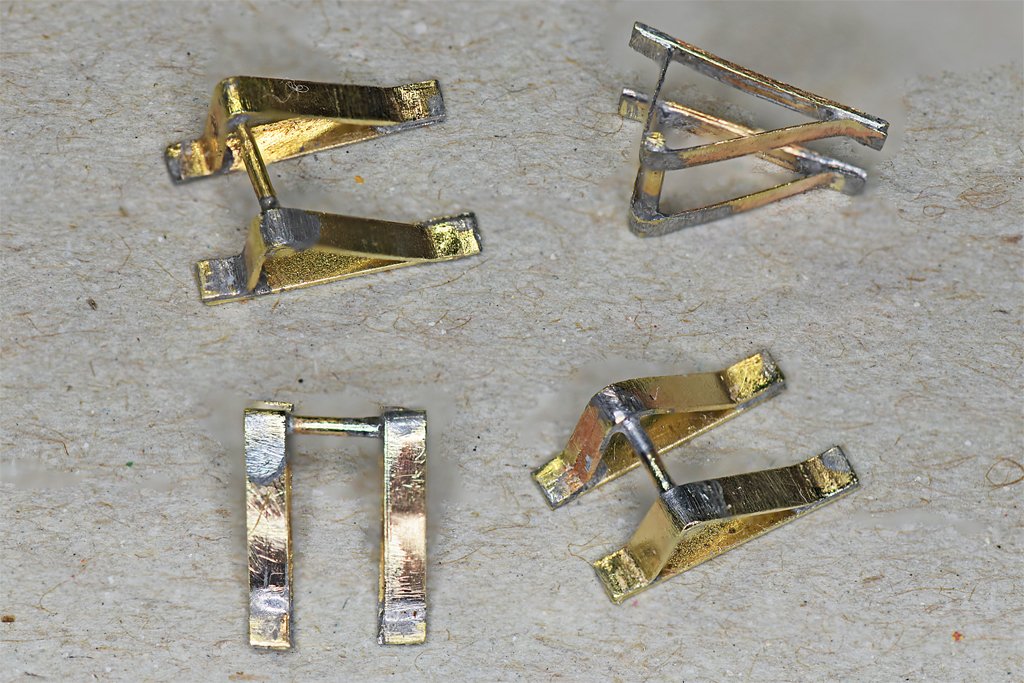
I have been making some of the small detail parts. Some of these were fire hose racks. Drawings for these are in the blueprint set, so I didn't have to guess at the dimensions. Still, as I converted the 1:1 dimensions to 1:48 the actual size of these parts didn't sink in. It was only when I started cutting the tiny pieces out of sheet brass that I realized this would be a bit more challenging than I had anticipated. The plans call for 3/8 inch (9.5 mm) metal plate. That comes out to 0.008 inches (0.2 mm) at 1:48 scale. I decided to use 0.005 inch (0.13 mm) brass for the front "D" shaped pieces. But that stuff is pretty flexible, so I made the rectangular back plates from 0.010 inch (0.25 mm) brass. The part the hoses hang over was made from 0.091 inch (2.3 mm) brass tubing. This is a bit over the true scale 0.083 inch, but the 0.091 inch tubing was what I had to work with. Here are the finished hose racks. The 0.91 inch brass tubing was sawn down the middle to create "C" cross section half tubes. Four of them have 0.146 inch (3.7 mm) long pieces of half tubing. One has a shorter 0.094 inch (2.4 mm) hose support. The longer parts are for fire hoses, and the shorter one is for the fresh water connection hose to a shore supply. These things were a test of my patience! Getting one end piece soldered to the tubing was fairly simple, but I had to reheat each of them several times to reposition the tubing in the correct position on the end plate. But when I tried to solder the other end piece to the tubing the whole thing unsoldered and came apart. The wet solder stuck the parts to the tweezers and everything was a mess! But if first you don't succeed ... and as you can see I finally got them done. The key to success was using an ancient aluminum tweezer-type heat sink dating back to the days (1960s) when we soldered individual long lead TO-5 package transistors onto circuit boards. I had the old Radio Shack part in my tool box. When I clamped it to the tubing close to the already soldered end piece it absorbed the heat and prevented that solder joint from melting. Still, I had to work quickly, and had to repeat the process several times to get the second end piece in the correct position. It was slow tedious work. These things are ridiculously small! I have a partially assembled 1:96 scale model of the USS Oklahoma City CLG-5. Someday I want to resume that build. But it has dozens of small parts like these hose racks - but half the size! I think I will have to use 3D printing for that build, and I will need a much better printer that the one I currently have!
- 464 replies
-
- 9
-
-
-

-
- minesweeper
- Cape
- (and 1 more)
-
George, Good to see you back in the workshop. That is an interesting rig in the photo. I have seen it in books but this is the first model I have seen that has the mainsail with the diagonal spar. Harold Underhill calls it a sprit-sail rig (Sailing Ship Rigs and Rigging, Brown, Son and Ferguson, Ltd., Glasgow, 1969, pages 13 and 72). The diagonal spar is called a sprit. He shows the sail plan of a Thames sailing barge Lady Daphne with this rig. So it wasn't limited to the Mediterranean.
-
For what it is worth, on mid 20th century US Navy ships with wooden decks the planks were laid over steel decks, with short stub bolts welded to the deck (it was really nasty trying to walk on that deck after the planks were removed for replacement). The planks had small diameter holes half way through to fit over the bolts, with a larger diameter hole above that for the nut. Caulking was hammered around the nut and a wooden plug was hammered into the hole over the nut. The blueprints specified that the wooden plugs be cut from the same type wood as the planks, perpendicular to the lengthwise grain of the planks. This left the "side view" of the wood grain exposed on the ends of the plugs, and not the "end view". When the plugs were installed the grain on the top of the plug was to be aligned with the grain in the planks to make the plugs as invisible as possible. So the intent was to hide the plugs. You could see the plugs if you were standing directly over them, but they were invisible from one or two decks above. I suspect this same technique was used in the 19th century to bolt planks to steel ribbed hulls. However, trenails were cut with the grain, so the end grain is visible and distinct from the grain of the planks. Even so, on freshly cleaned (holystoned) decks the trenails would not have been visible from more than a few tens of feet (several meters).
-
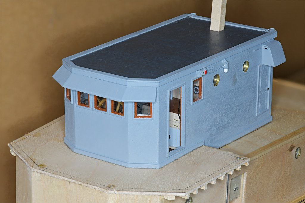
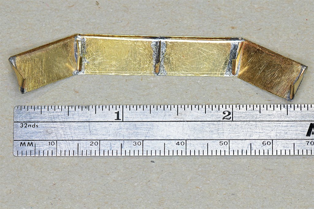
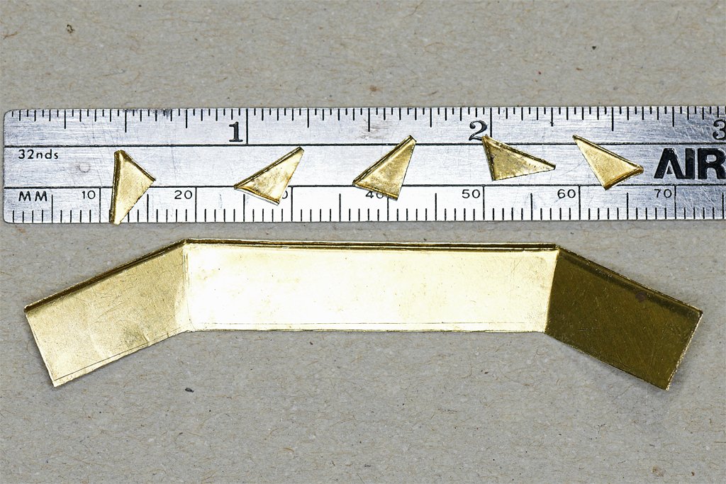
Today I added the "visor" or sun shade over the windows at the front of the O1 deckhouse. The parts were made from thin brass sheet. I used a new Photo Etched Parts Bender AB-4553 from joystarttools.com (China). I saw a smaller version of this tool recommended in another thread on the Forum. I got the larger version because I will need to bend some longer pieces when I get to the equipment on the after deck of the Cape. The tool is 5.52 inches (140 mm) on the long side, and the upper part can be rotated to use the long straight edge to bend parts almost 5.5 inches long. This was my first time using the tool and it worked as advertised. I made bends that were only about 1 mm (0.039 inches) wide. It was easy to use. The small triangular support pieces were made from 0.003 inch (0.09 mm) brass sheet. For the larger surface I wanted something a bit stiffer so I used 0.0065 inch (0.14 mm) brass. This was a bit less than the scale 3/8 inch plywood used on the ship - that would b 0.0078 inch (0.2 mm). The supports were soldered to the bottom side of the visor as shown on the photo right below. The 1 mm (0.039 inch) lip along the front edges of the visor stiffened the piece. On the real ship this was a strip of wood attached to the bottom front edge of the plywood visor. Here are a couple of photos showing the visor in place on the deckhouse. I have been looking forward to making this piece. It was practice using the bending tool. When I get around to making all of the minesweeping gear on the after part of the ship I will be bending a lot more small parts.
- 464 replies
-
- 13
-
-
-
-
- minesweeper
- Cape
- (and 1 more)
-
Vaddoc, I normally sand between paint coats because I use a brush and that can leave some brush marks. It also helps to make a smoother final finish. However, I used plywood for the deck house sides and tops on the Cape model, and it has some significant visible grain features even after I had sanded it smooth. Each coat of paint fills in a bit more, until the graininess is hidden. I used one or two coats of acrylic sealer, but this wasn't enough. You can see this on the lower deckhouse that hasn't been painted grey. With all the small details that have been added I won't be able to sand it anymore, so the final paint coat will be pretty thin, just to cover the scuff marks from the prior sanding and handling. Then a final coat of satin acrylic varnish will finish the paint job. I have already done this on the hull and main deck. In hindsight I suppose I should have used sheets of basswood for the deckhouses. The basswood I have has a much less grainy surface than the plywood.
- 464 replies
-
- 5
-
-
-
- minesweeper
- Cape
- (and 1 more)
-
Very nice work! My oldest nephew was Captain on one of these boats on the Mississippi, Ohio and Tennessee Rivers. He sent some nice photos of the river, and a few harrowing tales of floods and loose barges.
-
These are deck drains. The flat metal parts are 0.005 inch (0.13 mm) brass sheet. The drain pipes are 0.038 inch (0.097 mm) aluminum. The drain funnels were made from 0.062 inch (1.6 mm) and 0.092 inch (2.3 mm) telescoping brass tubing. The drain channels are 0.1 inch (2.5 mm) wide, to provide a size reference. Assembly was tricky. I soldered the brass tubing first, and then turned the end to create the "funnel" shape. The "U" shaped channels were then soldered together, using a wooden dowel to bend the brass strips and align the sides and bottom while soldering. These two steps weren't much of a problem. Then the "funnels" were soldered into the channel. This had to be done quickly, with a minimum of heat, to avoid unsoldering the parts of the channels and funnels. I had to repeat this a couple of times for each piece to get things aligned properly. The aluminum drain pipes were glued into the funnels with super glue (cyanoacrylate or CA). I made tiny "U" brackets from 0.005 inch (0.13 mm) brass strips to fasten the pipes to the deckhouse bulkheads. Here are some photos of the drains on the aft end of the O1 superstructure. The main deckhouse also has drains on the aft end port and starboard, and the O1 level bridge wing decks have drains port and starboard. I used aluminum wire because 1) i don't have brass rod the correct scale diameter, and 2) it is much easier to form the curves with the soft aluminum than with harder brass. But that meant I had to glue the aluminum and brass pieces instead of soldering. Epoxy would have been better for bonding aluminum to brass, and the brass parts to the wood superstructure. But little mechanical strength is needed in this application so CA should work OK. After the glue sets overnight I will brush the drains to clean them up and then paint them. The entire O1 level superstructure needs another light coat of paint, and then some satin acrylic varnish.
- 464 replies
-
- 17
-
-
-
-
- minesweeper
- Cape
- (and 1 more)
-
Tapering Masts and Arms the easy way
Dr PR replied to Johnny Mike's topic in Masting, rigging and sails
I have done the same thing, and it does work if you do move the piece back and forth past the center "dead zone." But if the piece is flexible you can end up removing more material on the ends than in the center because the disc sander is more "aggressive" at the higher speed outside edges than in the slower center. I have also placed a spacer on the platform to raise the piece above the center. -
Thanks for the complements fellows! For the vent there are supposed to be eleven "slats." I used 1/64 inch (0.4 mm) plywood for the slats and started out with them at a 45 degree angle. I prepared a spacer to set them at a uniform spacing. "The best laid plans ..." I only got eight to fit, and the upper slats are not at exactly 45 degrees. But the spacing is pretty good so it looks OK. Besides, it will be hidden under a ladder.
- 464 replies
-
- 4
-
-
- minesweeper
- Cape
- (and 1 more)
-
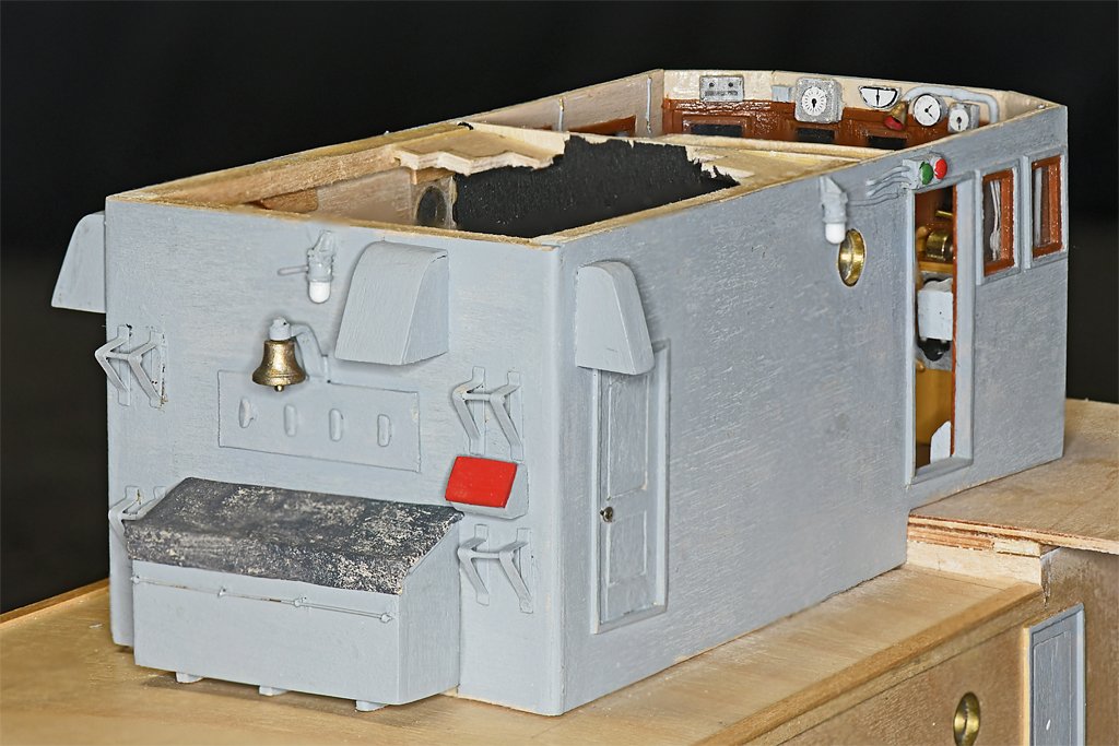
More details on the deck houses. I have put the "lid" on the O1 deckhouse. I still haven't attached the O1 level house to the main deck house. I have been adding some deck edge trim around the sides of the deck houses. While it adds some nice detail it also serves a very good modelling purpose. The house sides and decks are made of 1/16 inch (1.6 mm) plywood, with the decks resting on the top edges of the sides. Finishing the edges of plywood is trickier than the surfaces, with multiple porous layers to fill. The upper horizontal trim is 5/32 x 1/32 inch (4 x 0.8 mm), and the lower vertical piece is 3/32 x 1/32 inch (2.4 mm x 0.8 mm). These dimensions are pretty close to scale. The vertical piece conveniently hides the edges of the plywood deck. The real ship was built with 3/4 inch (19 mm) plywood house sides and deck. The trim served to seal the edges of the plywood from the weather. The main deck house has the same type trim as the O1 level house. There is also another 3/32 x 1/32 trim piece at the bottom of the deck house sides. The houses fit pretty tightly to the decks, but there are some slight gaps. These bottom trim pieces allow me to cover any gaps and seal the houses tightly to the decks. A vent trunk fits to the rear of the main deck house. Inside was a large fan that ventilated the engine room below. The blueprints and early photos of the MSIs show deck edge trim like on the house sides, and a hawser reel on top of the vent trunk. However, when I was aboard in 1969 both of the MSIs had an inclined ladder from the main deck to the top of the vent trunk. Steps had been added up to the O1 level. I will be adding the ladder and steps. Originally, if you were on the O1 level and wanted to get to the main deck you had two choices. There was a vertical ladder on the starboard aft side of the main deckhouse. Or you could go through the pilot house to the radio room, and down an inclined ladder in a companionway. Then you could go through the mess decks and passageway to the door at the port rear of the deckhouse (shown in this picture). I guess they got tired of taking the long way around and added the inclined ladder. The hawser reel was moved to the port rear corner of the O1 level, above the door. There was another addition to both MSIs inside a recess in the main deckhouse port side. There was a scuttle in the deck at the bottom of this recess. It was an escape scuttle from the mine sweeping generator room. Originally there was nothing in the recess. But somewhere along the line a locker was added at the top of the recess. I do not recall what was stowed in the locker. The recess was 3 feet (about 1 meter) wide, and the locker was about the same height. It would have been about 18 inches (about half a meter) deep. I'll be adding more small details to the main deckhouse sides, and planning for the life rails on the O2 level. I have also started on the mast. Conveniently, it was 12 inches (305 mm) square, and that is 1/4 inch (6.4 mm) at 1:48 scale. I used a 1/4 inch square dowel and rounded the edges slightly like the real mast.


- 464 replies
-
- 13
-
-
-
- minesweeper
- Cape
- (and 1 more)
-
Nice work!
-
Tapering Masts and Arms the easy way
Dr PR replied to Johnny Mike's topic in Masting, rigging and sails
Are you using the same taler for the full length of the mast? A long tapered cone? From what I have read the mast is more like a long half oval, tapered more on a curve than a straight line. Widest at the deck (partners) and tapered in quarter lengths in a non-linear fashion. Divide the length of the mast from the deck to the crosstrees into four sections. The relative diameter at each quarter is: deck (partners) 1.0 1/4 0.984 2/4 0.933 3/4 0.857 crosstrees (hounds) 0.75 I used to use a simple taper using sandpaper for the masts when I first started building ship models (50+ years ago). But when I learned real mast weren't built this way I started using the 4/8/16 tapering method in order to get better control of the mast shape. It is a lot easier that it sounds, and produces a more accurate mast shape. YT pointed out a problem with your method. With a disc sander the rate of material removal is proportionate to the speed of the sanding surface. The outer parts of the wheel rotate faster, and the center doesn't rotate at all for practical purposes. You can't use the entire diameter for tapering because the center doesn't do much, if anything. You can modify the process by placing a spacer to raise the work piece above the center, so the sanding surface is moving, but it will still be faster on the outside of the disk than near the center, and will be more aggressive at removing material. It will be very difficult (but not impossible) to get an accurate mast taper this way. -
Paul, Very nice build! When you started I hoped you would do the ship justice, and now I am pleased to see you doing such nice work.
-
Planking problems
Dr PR replied to Mrgj24's topic in Building, Framing, Planking and plating a ships hull and deck
You are not tapering the planks. The distance between the bulwarks and the keel is greater midships than it is at the bow and stern. Therefore each plank MUST be tapered proportionately, wider midships (full plank width) and tapered narrower at bow and stern. Look at the tutorials and articles about planking. Even when the planks are tapered they must be twisted/bent so they lie flat on each bulkhead/frame. There are many suggested techniques to accomplish this bending, but most use some combination of water or alcohol and heat. I have built a number of plank on bulkhead hulls - all single layer planking - and have found a simple and effective technique that seems easier that all the other suggested methods. I use a small planking iron (actually a quilting iron used for making quilts) and wet the planks. The steam from the heated planks carries heat into the wood and this makes it pliable. Then when it cools it holds its shape. https://modelshipworld.com/topic/37060-uss-cape-msi-2-by-dr-pr-148-inshore-minesweeper/?do=findComment&comment=1074225 https://modelshipworld.com/topic/37060-uss-cape-msi-2-by-dr-pr-148-inshore-minesweeper/page/4/#elControls_1075263_menu -
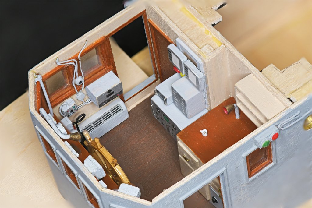
I am fortunate to have some close-up photos that show the details. The blueprints are good for showing the equipment, but they don't show the small details such as the wiring or notices/instructions attached to bulkheads. And often the equipment is different in the photos, or in the positions. For example, on the starboard interior bulkhead of the pilot house the blueprints show two AM-215/U amplifiers below the windows. However, I found the data sheet for this amplifier and the dimensions were larger than shown in the blueprints. They were too large to fit two as shown in the blueprints. And the pilot house photo shows only one, in the position I placed it in the model. I don't have enough photos of the Cape as it was in 1969 when I was aboard. For example, I don't know what was attached to the exterior of the pilot house forward bulkhead, in the open bridge. One photo does show a phone handset cradle and a box (for a sound powered phone headset?) on the starboard side, but it doesn't show what else might be on the center or starboard side of that bulkhead, such as a speaker, light, etc. I haven't found those details in the blueprints. While I was on the USS Oklahoma City CLG-5 I took thousands of photos. I even thought that I might someday make a model of that ship so I went around photographing almost every exterior surface, plus the bridge and pilot house. Even so, there were two places (under the port and starboard boat decks) that I did not have pictures. Those photos were invaluable for creating the CAD model as the ship was in the summer 1971. I have the 1959 blueprints, but the ship had undergone many modifications by 1971 - some pretty extreme - that weren't shown in the drawings. Just about any photos are good. They may be of sailors working or goofing off, but in the background are details.
- 464 replies
-
- 5
-
-
- minesweeper
- Cape
- (and 1 more)
-
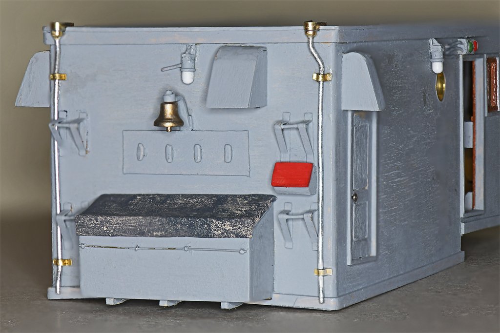
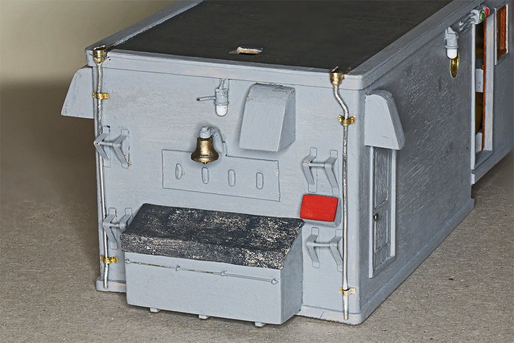
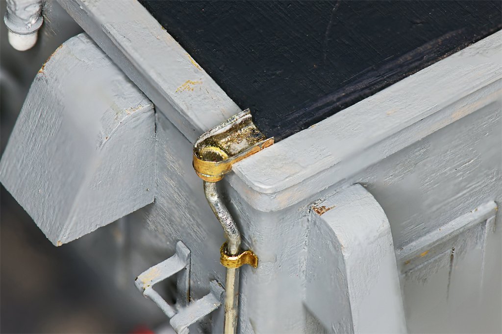
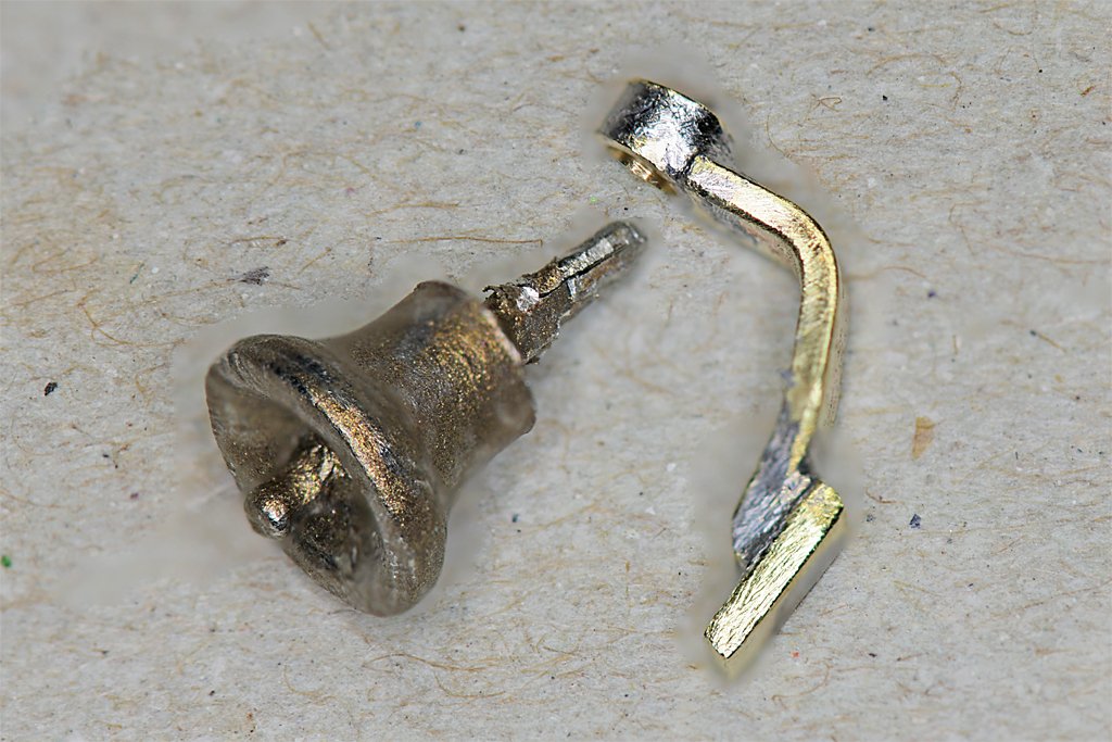
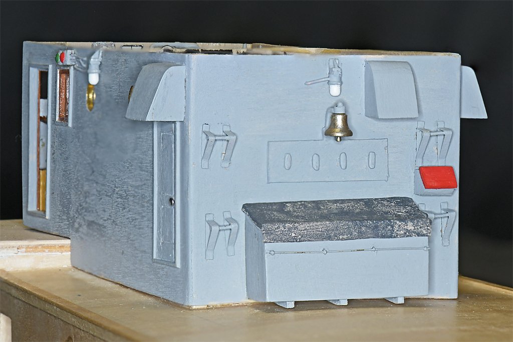
Still working on the small details for the O1 deck house. The bell bracket was made from 0.030 inch (8 mm) brass. The bell is from Bluejacket Ship Crafters (1/4 inch, part F0483). I have made bells from scratch, but it was much easier to order the bell while I was also ordering the propeller. The parts on the right are brackets to belay signal halliards. Here are a couple of photos of the signal bridge. the flag bag (flag locker) has a "canvas" cover. It was made from some of the scrap silkspan I had left over from the topsail schooner build. It was painted off-white for the schooner sails so I brushed on some Tamiya "German Grey" (XF-63). This is what I will use for the O1 and O2 level decks. A board with cleats for securing halliards is above the flag bag, with the halliard belays on either side. The thing with the red top is the shore connection box where the ship was "plugged in" to shore power while docked. There are three vent hoods from the fan room at the aft end of the O1 level house.
- 464 replies
-
- 13
-
-
-
- minesweeper
- Cape
- (and 1 more)
-
Jim, I am sure the open exposed bridge did give better views of what was happening. This was especially critical before radar and sonar when all eyes on watch was very important. On the USS Oklahoma City CG/CLG-5 most of the open bridge had been enclosed, and the bulkhead between the enclosed bridge and pilot house had been removed (the USS Little Rock CG-4 museum ship still has the bulkhead between the bridge and pilot house). However, we always stepped out to the open wing of the bridge to look around before executing a turn, and all maneuvering for UNREPS was done from the open bridge wing. Still, I would like to think standing on an open bridge with freezing water sloshing over your feet for four hours did build character!
- 464 replies
-
- 2
-
-
- minesweeper
- Cape
- (and 1 more)
-
It had an open bridge, but with a windshield on the bulwark and a canvas awning overhead. But it was cold and windy, and pretty wet when it rained. In heavy seas we could take water over the bulwark - once I had several inches of water sloshing back and forth on the deck, and wet feet. When it got really nasty I would step into the pilot house to warm up. Many (most?) US Navy ships had open bridges until after WWII. I guess it was supposed to "build character" for the watch standers. In the 1950s many ships had the bridges enclosed, with open wings.
- 464 replies
-
- 3
-
-
- minesweeper
- Cape
- (and 1 more)
-
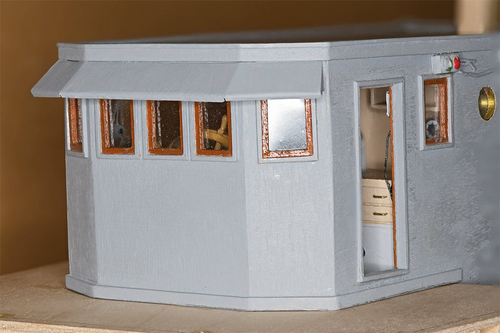
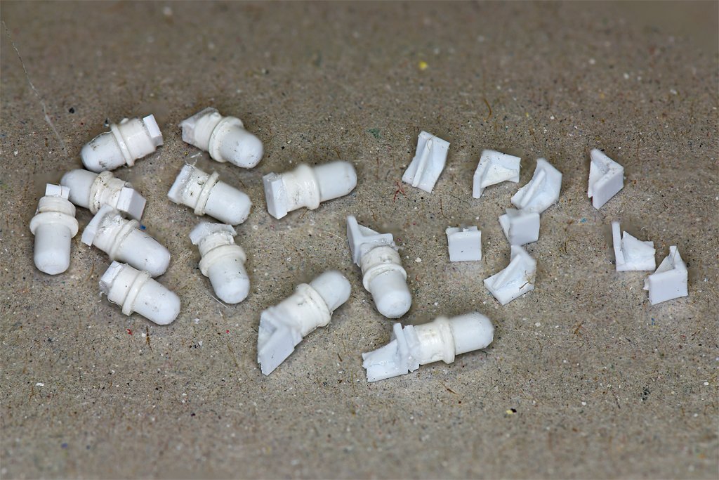
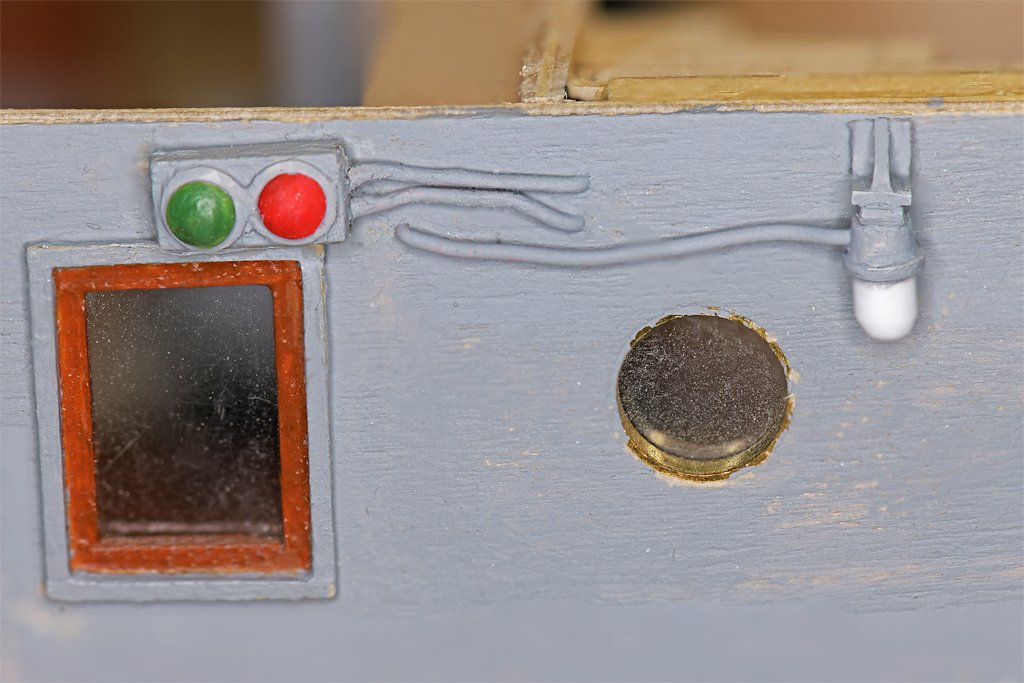
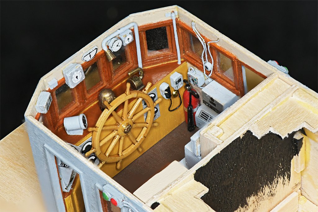
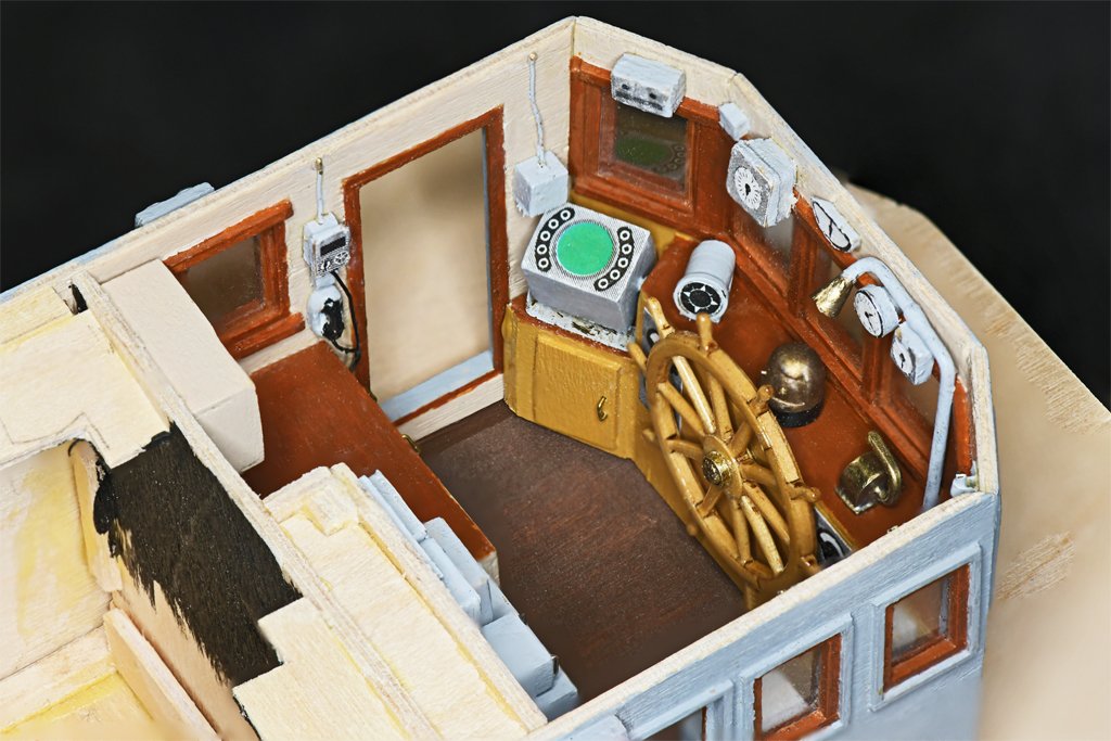
Here are a few more small details. The ship had several lights on the external bulkheads to illuminate the decks at night. I had the approximate dimensions and a 3D CAD file from the Okieboat CAD model. All I needed to do was make them in styrene. I used two sizes of styrene tubing - 0.100 and 0.125 inch (2.5 and 3.2 mm) diameter (left). I chose tubes instead of rods because they would fit concentric around a center rod and I wouldn't have to machine all of the dimensions. The base was turned and shaped with files to get the rim around the light. I didn't have the appropriate size rod so I rounded a piece of 0.0625 inch (1.7 mm) square styrene for the tubing to fit onto. After the glue set the end of the "bulb" was rounded with files and a 0.022 inch (0.6 mm) hole was drilled through the lamp base for the wiring. The next step was to cut pieces of a 0.100 inch (2.5 mm) angle for the mounting bracket (right). A bit of 0.015 inch (0.4 mm) styrene was shaped and glued into the angle. A small piece of 0.030 x 0.060 inch (0.8 x 1.5 mm) styrene was glued to the top of the lamp assembly, and the mounting bracket was glued onto this. The pieces were painted and this finished the lamp assemblies. I know I will need six or seven of these but I made a dozen. I will choose the best for the model. The photo on the right shows a lamp mounted on the port bulkhead of the O1 deck house behind the pilot house. A two colored Polarity Light is mounted above the window over the chart desk. The wiring for the lights is 0.020 inch (0.5 mm) copper wire. Ideally there would be a short "stuffing tube" around the wires where they enter the light housings, and another where the wires penetrate the bulkheads, but I couldn't figure a way to make these repeatably at this scale. The deck house sides have been painted with an acrylic base sealer, two coats of grey acrylic paint, and sanded. I will add another coat of paint, sand again, and finish with a clear satin acrylic varnish. Here are a few more photos of the pilot house after the front bulkhead was attached. The compartment was 9 feet (3 meters) wide with just enough room for the helmsman at the wheel and the navigator at the chart desk and radar. I am adding details to the exterior of the O1 level deckhouse and am about ready to put the O2 level deck over the house. This will also involve making the footing and attachments for the mast. There are actually relatively few wiring details on the exterior of this ship. It has wooden bulkheads that were framed much like ordinary house construction, and most of the wiring was placed inside the walls. This is in contrast to metal ships with thin (3/8 inch or 10 mm) steel plate bulkheads where much of the wiring is routed externally. There were railings around the O2 level on top of the deck house, and a few assorted odds and ends on the O2 level.
- 464 replies
-
- 12
-
-
-
- minesweeper
- Cape
- (and 1 more)