
HOLIDAY DONATION DRIVE - SUPPORT MSW - DO YOUR PART TO KEEP THIS GREAT FORUM GOING! (89 donations so far out of 49,000 members - C'mon guys!)
×


Dr PR
-
Posts
2,441 -
Joined
-
Last visited
Content Type
Profiles
Forums
Gallery
Events
Everything posted by Dr PR
-
 If you want to make a living at modeling then you need to know what the customer wants. It seems to me that there are three types of models. One is what the builder likes. The second is an attempt at historical accuracy. The third is a product that will sell commercially. If you want to sell your models you should investigate what is selling. Some commercial models are cheap junk intended as "souvenirs" for the average tourist who wouldn't know a ship from an elephant. Accuracy isn't important. "Pretty" is. They are for the tourist market, and are produced in large quantities. At the other extreme are the very accurate models built to order for specific customers. These are representations of vessels in the state the customer wants them built. Look at some of Valeriy V's exquisite models for examples. These are one-off models built for a single buyer. In between are builder's models and "Admiralty" style models intended to show the buyer of the real ships what they would look like. These tended to have lots of polished brass and varnished wood that wouldn't be seen on the real vessel. What do you want to do?
 -
Harvey, I don't know how I have been missing this build! Nice work on a very interesting vessel.
-
Valeriy, Beautiful work, as usual! I like the all metal construction too. You have access to the inside surfaces and joints, and that lets you get a good strong solder joint. You can leave a bead of solder on the inside of the joint because it won't be visible from the outside. Another problem has sometimes happened to me when I used a motor tool rotary wire brush to remove excess solder from the outside (visible) joints. I want to get clean sharp joints, but if I remove too much solder the joint is weakened and breaks easily. Leaving the solder bead on the inside keeps the joint strong. Plexiglas (acrylic) probably wouldn't be a good choice if you are sheathing the core with soldered brass parts. Plexiglas melts easily, and who knows where it will flow. It could mess up the surfaces the brass should fit against. It is good to see you are still well and working on the model!
-
Tom, I would like to take credit for remembering all of that - especially the equipment model numbers - but I am working from blueprints with complete lists of everything from type and numbers of screws to the make and model of the radar. To be honest, I don't remember much of it. You made me curious, so I looked at my DD214 and all it says was "discharged," "honorable," and "strength adjustment." The war was winding down and the Navy had too many junior officers. Basically it said "Thanks for your service, good bye, and don't let the doorknob hit you in the rear."
- 464 replies
-
- 6
-

-
- minesweeper
- Cape
- (and 1 more)
-
Well, it was better than swimming out with a hammer and beating on them!
- 464 replies
-
- 8
-

-
-
- minesweeper
- Cape
- (and 1 more)
-
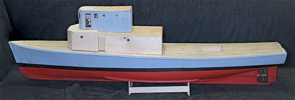
Thanks to everyone for your comments and likes. Here is a bit more progress: I have started assembling the O1 level superstructure. The sides of the pilot house are attached to the after pilot house bulkhead and the after bulkhead on the deck house. Here are a few views of the pilot house details before the forward bulkhead is attached. The deck was covered with brown linoleum tiles. I won't try to replicate the tile lines or the random pattern - they are too small to see at this scale. Here are a couple of photos of the deck house on the hull. The front and top of the O1 level are not attached yet, and are just sitting there. The O1 house is not attached to the main deck level house. Likewise, the main deck level deckhouse is not glued to the hull. There are still a lot of details to add to the superstructure and it will be easier to work on the parts off the hull. The next step will be the bulwark around the open bridge. For that I will remove the O1 level house so it isn't in the way. You can see one of the characteristics of minesweepers - a high pilot house up forward. This helps to see mines in the water ahead. Lookouts were posted on the O2 level above the pilot house to watch for mines. They carried M1 Garand rifles, and I was stationed there with a Browning Automatic Rifle (BAR). We were to shoot at any mines we saw, primarily to mark the location for the 50 caliber machine gun crew at the bow, and so the helmsman could try to avoid the mine. If we got lucky we might even detonate the mine, or sink it. We never fired at a real mine while I was aboard.

- 464 replies
-
- 14
-

-
-
- minesweeper
- Cape
- (and 1 more)
-
The boot topping and the waterline are not the same thing. The bottom of the boot topping is usually about the light load waterline - no fuel, ammunition or crew. Like the ship came from the shipyard before commissioning. The top of the bott topping is about the full load waterline - maximum fuel, stores, ammunition and crew aboard. More than the normal load. The normal operating waterline is somewhere between the light and full load, somewhere about the middle of the bott topping. Look for the draft marks to show where the normal operating water line should be. Add to this the fact that these waterlines changed every time new equipment, guns and such were added, and it is a bit tricky figuring where to paint the boot topping on a model. Given this, remember that ships stationed overseas often did not have the resources of a shipyard and drydock when repainting, and the resulting boot topping can be just about anywhere the crew painted it.
- 37 replies
-
- 1
-
-
- Pillsbury
- Clemson-class
- (and 1 more)
-
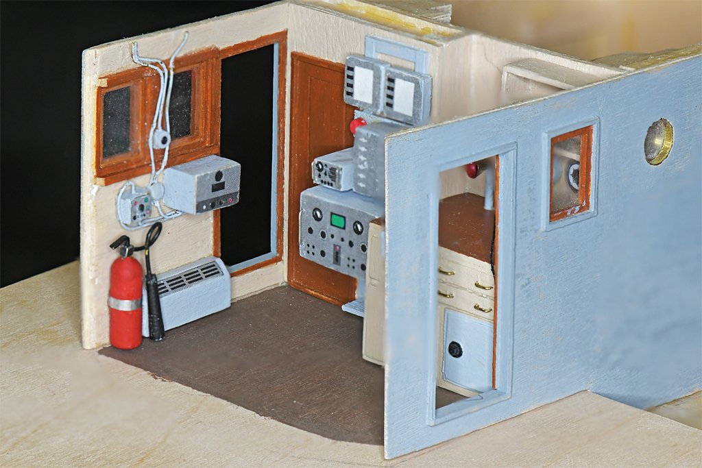
John, The doors on the sides of the pilot house will be open, and the interior will be visible through them. The side windows will offer a bit of a view. But the front windows will be hidden under a canvas cover over the open bridge. I suppose if you use a dental mirror or fiber optic camera you could see most of the detail.
- 464 replies
-
- 6
-
-
- minesweeper
- Cape
- (and 1 more)
-
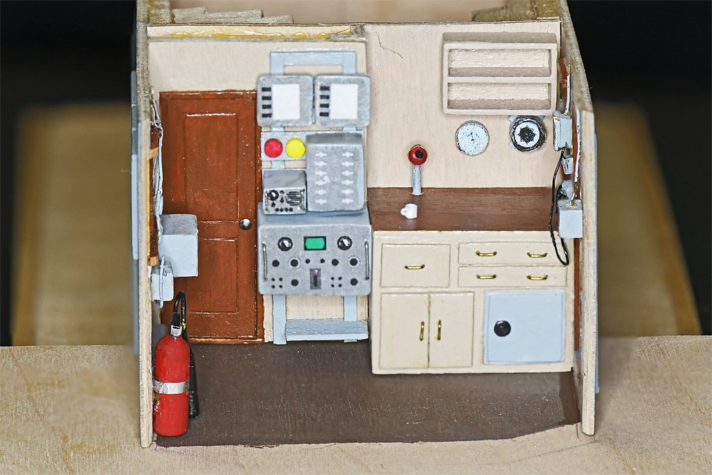
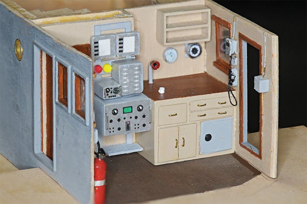
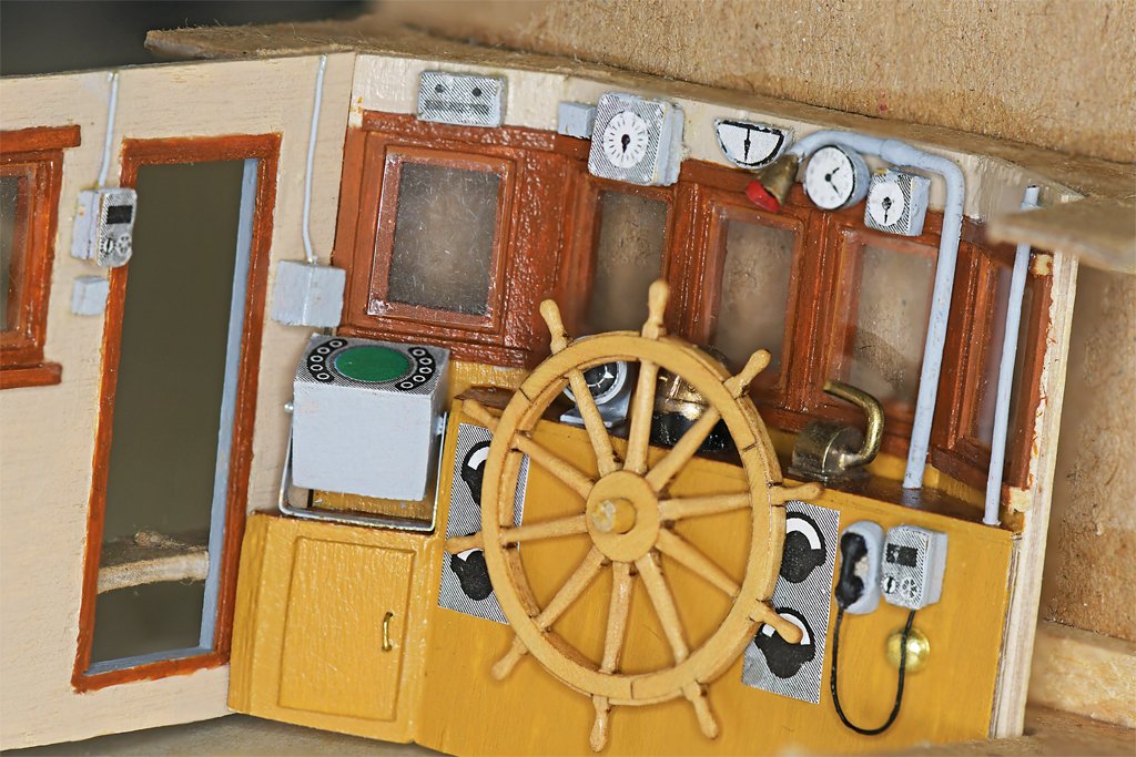
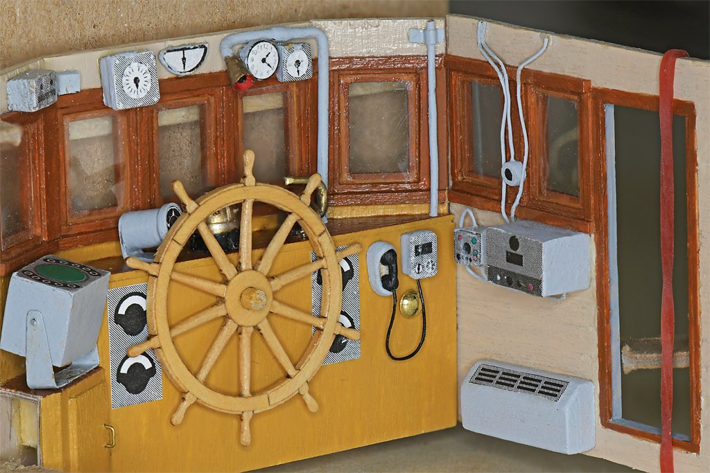
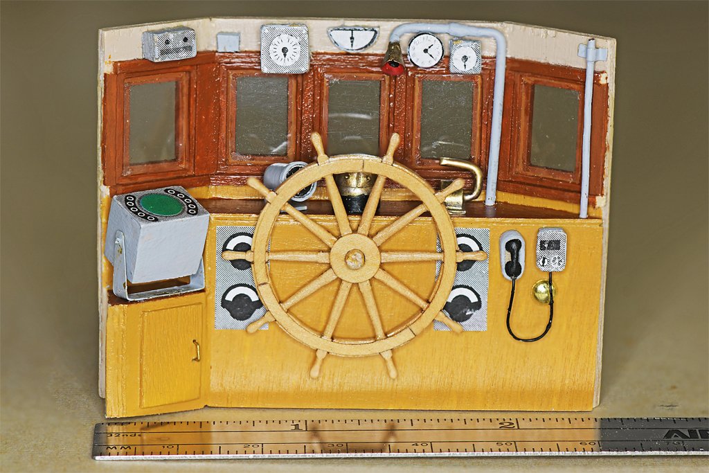
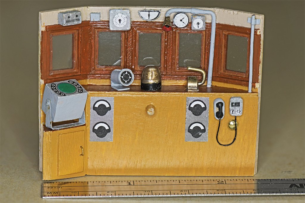
I needed one more detail to finish the forward bulkhead of the pilot house - a phone. The Navy used sound powered telephones (current was generated by the microphone in the handset) for internal communications because they required no external power. The sending and receiving unit could be an ordinary looking telephone handset or a separate microphone and earphones. There were three handsets in the pilot house and on the bridge. I carved this one out of a 6 mm (~1/4 inch) piece of boxwood. It is pretty crude, but good enough for this use. The handset is housed in a cradle It took about six hours to carve this one. I need two more! You can see the handset on the right in these photos, next to the phone system call unit (hand cranked to generate the ring signal.). At left center is the radar unit. two pairs of tachometers for the engines flank the wheel, with the phone system to the right and a bell below the telephone call unit. On the shelf in front of the wheel are the main gyro (left), magnetic compass (binnacle, center) and the engine control (throttle) on the right. Above, from left to right, are the gyro amplifier, the small windshield wiper control, the rudder angle indicator, clinometer, voice tube, clock and propeller shaft rotation indicator. In these photos I have placed the front bulkhead and side bulkheads in the alignment jig to show how the pieces fit together. Not much is on the port bulkhead - just a sound powered phone call unit (less the handset). On the starboard bulkhead are an amplifier and control unit for the radios, and a heater. The CO2 cylinder will fit at the angle in front of the heater. The Engine Order Telegraph will be positioned on the deck beside the heater. I suppose I could add some more wiring here and there, but it wouldn't be visible, so I guess the pilot house interior is complete - except for one more telephone handset on the port bulkhead beside the chart table. I guess I will use the Syren 1 - 1/4 inch wheel, even though it is 25% oversized (should be 1 inch or 4 feet at full scale) and ten spokes instead of eight. No one but me will know the difference. I will now take a break to do the taxes as Treasurer for a non-profit. That could take a few days to two weeks.
- 464 replies
-
- 12
-
-
-
- minesweeper
- Cape
- (and 1 more)
-
Steve, Thanks! I am printing the "faces" of the instruments on my laser (actually LED) printer, on ordinary printer paper. Then I cut them out and glue them to the instrument body. This works OK for the wooden parts. But the dial face on the EOT came out a bit the worse for wear. I soldered all the parts together, including a pin for the EOT handle to attach to. Then the paper "dial" face was glued on. So far, so good. But when I soldered the handle onto the pin (briefly) the dial face became heated and distorted. It looks like some of the ink flaked off, so you can't read the lettering any more. It was probably the solder flux that distorted the printing. But it will be inside the pilot house and almost invisible, so it will work OK.
- 464 replies
-
- 8
-
-
- minesweeper
- Cape
- (and 1 more)
-
Ken, It would be appropriate to have a Chief for the coffee mug (I don't know if I ever saw a Chief without one). However, the highest ranking enlisted man on the Cape was a 1st Class Bosun's Mate.
- 464 replies
-
- 2
-

-
-
- minesweeper
- Cape
- (and 1 more)
-
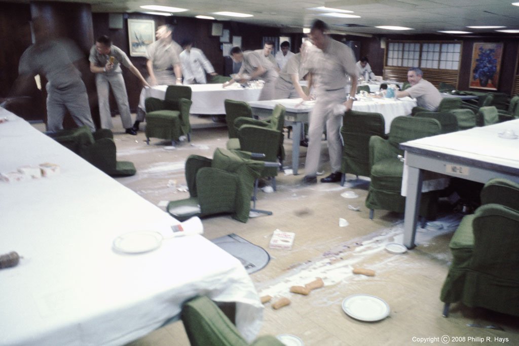
Terry, The wardroom tables on the USS Oklahoma City CLG-5 had smooth plastic tops covered with table cloths. The tables were supposed to be bolted down, but some had been repositioned without fastening. This wasn't a problem until we were chassed out of White Beach, Okinawa, by a typhoon that made a sudden appearance (before weather satellites). While turning to put the wind on the starboard bow (northern hemisphere) we took some 30+ degree rolls. This was while the wardroom was seating for Sunday morning brunch. I had been topside taking photos of the storm and had just stepped up to the wardroom door when the ship took its heaviest roll. There were crashes from one end of the ship to the other as equipment broke loose from bulkheads and furniture slid around. This is what I saw when I opened the door - breakfasts and broken dishes on the floor and people and furniture sliding around on spilled sugar and cereal. The South China Sea and Gulf of Tonkin were hit by a series of storms that lasted a month and a half. We rode through five typhoons and a tropical storm in three weeks (and dodged two others)! After Okinawa we gave up and went to Yokosuka, Japan, for repairs.
- 464 replies
-
- 8
-
-

-
- minesweeper
- Cape
- (and 1 more)
-
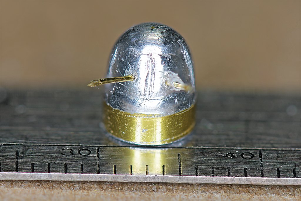
More fiddly bits. The binnacle was turned out of a piece of 1/4 inch (5 mm) aluminum rod - part of a small wind chime (I didn't have a brass rod the proper diameter). The dome was shaped using a hand drill and files. The binnacle on the ship had two sliding doors that closed in front of the compass rose. To simulate this I carved the aluminum with a #11 blade and a tiny chisel made from a dentist's tool. It was a slow process! The two thin brass rods sticking out were for the two knobs. On the right the binnacle is in position in front of then helm. It was painted with the brushed bronze paint I used on the propeller. A few other small details can be seen. The voice tube from the bridge hangs over the helm station. The tachometers for the engines are on either side of the helm, and a sound powered phone call station is at the lower right. A phone hand set and a few more pieces will be added beside the binnacle and above the windows. Here is the lee helm or Engine Order Telegraph (EOT). It is made from 11 different pieces. It is 1.14 inches (29 mm) high from the base to the top of the handle (a bronze belaying pin). That is 4 feet 6 inches (1.4 meters) at 1:1 scale. I buffed it up good and then applied a layer of clear acrylic varnish to keep the shine. However, it appears the varnish may have reacted with the brass, and it is a lot duller a day later! I don't know if the EOT was ever used. The ship had a throttle beside the binnacle that the helmsman could use to control the engines. However, I do recall using standard engine orders - Ahead/Back 1/3, 2/3 and Full - when pulling away from the pier, so maybe it was normally used. The throttle might have been used to change propeller speed a few RPM in station keeping while sweeping mines. The 6 inch (150 mm) 15# CO2 bottle was turned from a 0.185 inch (4.7 mm) brass rod. The cone is styrene rod. I still have 14 more pieces to go on the forward bulkhead and side bulkheads of the pilot house.


- 464 replies
-
- 14
-
-
-
- minesweeper
- Cape
- (and 1 more)
-
The weather (windward or upwind side) backstays are tightened to take the strain on the mast. The lee (downwind side) backstays are slackened, and the tackle is moved, to allow the boom to swing outboard. As Trevor said, when the boat gybes (changes course so the wind comes from another side) and tacks while running into the wind (changing course so the wind is coming from ahead on another side on the bow) the running backstays have to be adjusted to support the masts from the windward side. It keeps the crew busy when course changes are frequent.
-
The dinnerware (cups, plates, bowls and mugs) were all ceramic.
- 464 replies
-
- 4
-
-
- minesweeper
- Cape
- (and 1 more)
-
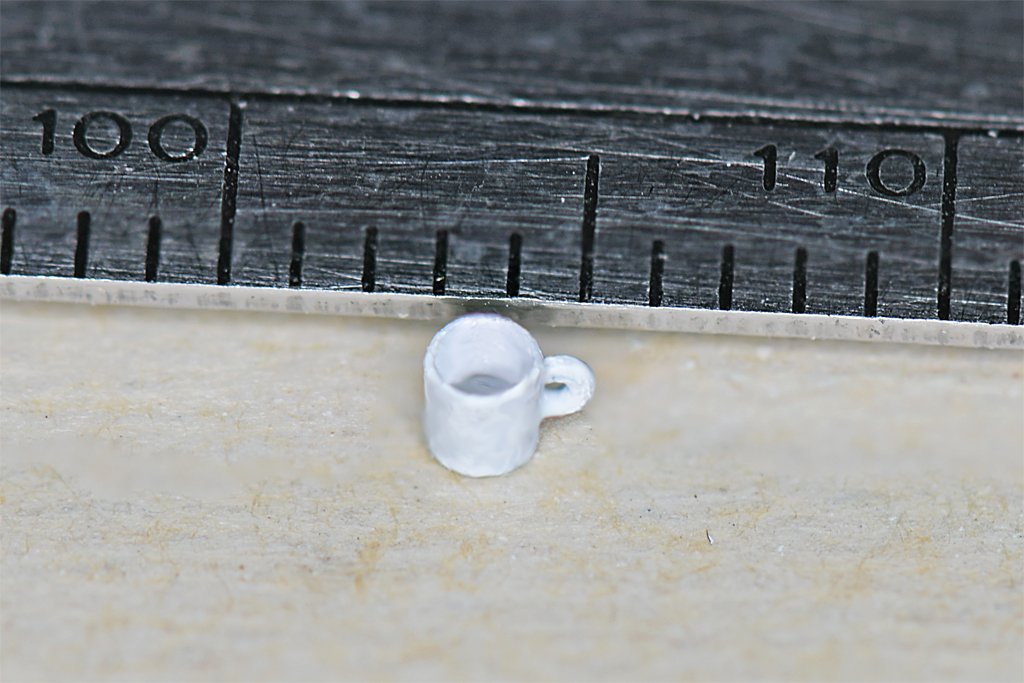
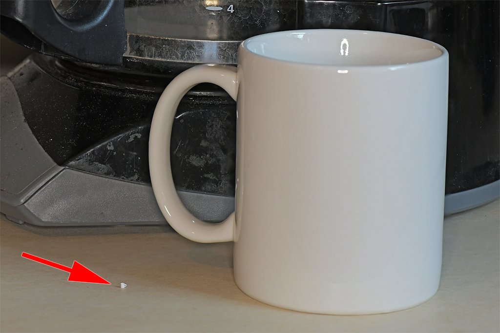
I don't recall mugs without handles, so that must have been before my time. If I was working in 1:24 the model would be 4' 6" long (1.4 meters). As it is, at 1:48 it is 28 inches (711 mm) long and pretty large. And I must confess, I didn't paint the Navy seal on the mug - that picture was a Photoshopped fake. Here is the real 1:48 coffee cup on the chart desk.
- 464 replies
-
- 9
-
-
- minesweeper
- Cape
- (and 1 more)
-
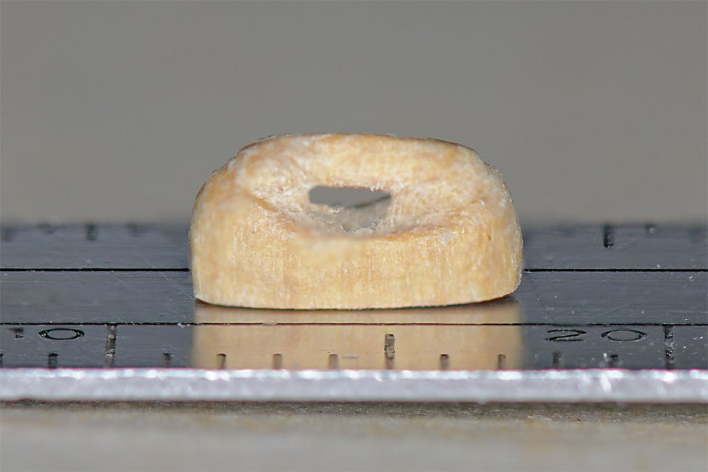
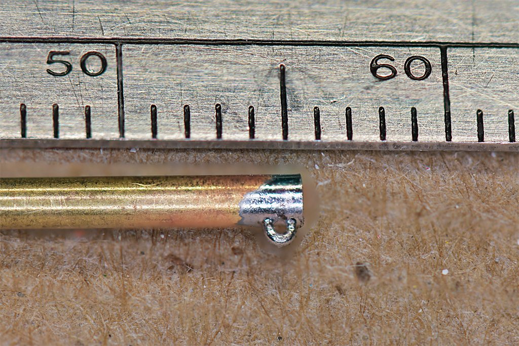
One coffee cup coming up! First I drilled out a piece of 1/16 (1.59 mm) brass tubing to about 0.050 inch (1.3 mm). Then I drilled two 0.016 inch (0.4 mm) holes for the handle. The handle is 0.012 inch (0.3 mm) brass wire. The wire was soldered into place and the interior filed to remove the wire stubs. Then the cup was cut off from the tube, polished and painted. The paint needs to dry more before a second coat is applied. Here is the 1:48 scale 3 inch (75 mm) cup next to the real 1:1 thing. I calculate it will take about 120,000 "cups" from the scale cup to fill the real thing. And here is the navigator's cup on the chart desk. In the real Navy you would never place a coffee cup on the chart desk. But the Cape was McHale's Navy, and we went by Cape rules. The really difficult part was painting the Navy seal on the cup. That took a steady hand!

- 464 replies
-
- 20
-
-
-
-
- minesweeper
- Cape
- (and 1 more)
-
Coffee cups - a good idea! But at 1:48 a 3" (75 mm) diameter cup would be 1/16 inch (1.6 mm) diameter. That should be doable. Start with a 1/16 inch (0.0625) brass tube and drill it out with a 0.052 inch drill. That will leave 0.005 inch (0.127 mm) sides for the cup. The handles could be 0.012 inch brass wire. However, I have been working on the binnacle and it had a two-part sliding cover over the front with knobs to pull them open. I broke two 0.013 inch drill bits (using a hand held pin vise) making holes for the 0.012 inch dimeter wire "knobs." I wonder how many more bits I have left? Maybe I'll just solder the handles to the cup!
- 464 replies
-
- 5
-
-
- minesweeper
- Cape
- (and 1 more)
-
John, Thanks. I don't remember what we had on the shelves, but at 1:48 they are way too small to read anyway. Steve, It is always helpful to observe people who know what they are doing. Who are you watching?
- 464 replies
-
- 5
-
-
- minesweeper
- Cape
- (and 1 more)
-
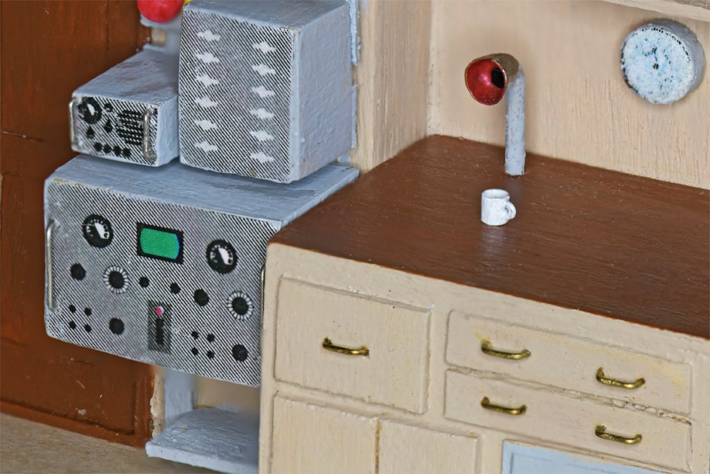
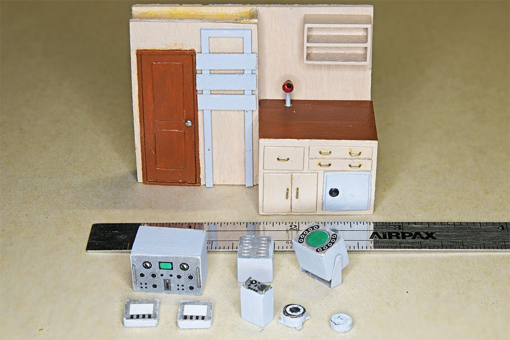
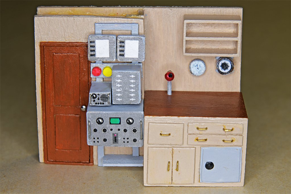
Here is a bit more progress. This is the pilot house aft bulkhead and some of the instruments that will be mounted there. The large box is the Mk VII Magnetic Sweep Controller. Below it are two Navigation Light Panels. The small box is a KY-83S Keyer. Above it is a Transfer Panel for the Mk VII. At lower right are a gyro repeater and a barometer. Most of these parts mount on the gray rack to the right of the radio room door. I found a photo of the Keyer and used it to create the graphic on the face of the box. The Mk VII controller graphic is fictional - I can't find a photo of it. The Transfer Panel graphic is also guesswork. The gyro repeater and barometer graphics are actual photos. The light panel layout is shown in the blueprints, but the graphic is guesswork. The box that is mounted on a bracket is the ship's EDO Model 320A radar unit. It will be mounted on the pilot house forward bulkhead. Here is the equipment mounted in place. The red object is the General Alarm switch, and the yellow one is the Chemical Alarm. The actual units were octagonal with a handle, but th 1:48 scale they are too small to model correctly. The shelf below the Mk VII was for an electric megaphone. I guess I should put some books in the bookshelf over the chart table.
- 464 replies
-
- 15
-
-
-
- minesweeper
- Cape
- (and 1 more)
-
I have been working on some of the fiddly bits in the pilot house. These are the "megaphone" mouthpieces for the voice tubes. Four will be visible: one on the O2 level above the pilot house, one on the open bridge, one in the pilot house above the helm, and the fourth is on the chart desk in the pilot house. I took the dimension from the blueprint drawings, and printed the (very tiny) paper template from my CAD system. I made the pieces from 0.005 inch (0.13 mm) brass. Here is a photo of the completed parts (left) on top of the chart desk on the aft bulkhead of the pilot house. One of these tubes came up under and stands above the chart desk surface where the navigator can talk to the bridge or O2 level station. The safe and drawers are shown in detail on one of the blueprint sheets, but I had to estimate the actual dimensions. On the right is the chart desk positioned against the aft bulkhead. Just to the right of the door to the radio room is a frame for an equipment rack. Several pieces of equipment will be mounted there. All of this is like making dollhouse furniture. This is the forward bulkhead for the pilot house. The shelf in front of the helm will support a magnetic compass, a gyro repeater, and propulsion control unit (throttle). There will be several instruments above the windows, and four tachometers for the engines will be mounted on the lower front on either side of the helm. The low shelf at the left will support the navigation radar control unit. This helm is the Syren 1-1/4 inch (32 mm) kit that is 5 feet (1.5 meters) diameter at 1:48 scale. This is oversized - I learned from the blueprints that the original wheel was 4 feet diameter, or 1 inch (25 mm) at 1:48. The kit has 10 spokes and the original had only eight. If I can find an eight spoke 1" diameter wheel I will use it instead. Maybe I will scratch build one. The "mahogany" window trim came out pretty good, especially after a coat of acrylic satin varnish. The vertical parts were paneled in a light colored wood, hence the "straw" color (you might recognize from my schooner build). This definitely was not a stock Navy paint color. The panel above the windows, and the aft pilot house bulkhead and chart desk front are painted an off white buff color. Again, this isn't what the blueprint painting schedule called for. It says to paint the walls and overhead green. The Navy did use a pale "puke" green in interiors, but the photos I have show an off white color with no hint of green (maybe the colors faded in the slides before I scanned them). And overheads were always painted white.


- 464 replies
-
- 15
-
-
-
- minesweeper
- Cape
- (and 1 more)
-
Roel, I have followed this build over the years, and it has turned out beautiful! If the damage is on the port side, that means you were on the bridge's starboard, so you had the right of way! I guess the bridge just couldn't move fast enough to get out of the way.
-
The Syren ship's wheels are very nice: https://modelshipworld.com/topic/37060-uss-cape-msi-2-by-dr-pr-148-inshore-minesweeper/?do=findComment&comment=1093274
-
Your eyes adapt to the darkness in less than 15 minutes, and it is surprising how much you can see in the "dark." We could see unlighted fishing boats in almost any clear weather and calm seas. Heavy seas and rain made it more difficult. But even a small light could be seen from a great distance. Fishing boats often had a small light pointing down into the water to attract fish, and these were very easy to see at a great distance. You can also see the glow of bow waves and wakes from light emitted by microscopic marine creatures. I didn't have any trouble walking around on deck at night, and some of our decks were painted dark gray.
-
The Grecian was a beautiful ship. It will make a beautiful model! Be careful working with the thin pear wood, especially with the rear seats and thwart. That thwart is cut across the grain, and it will break very easily (I speak from experience)!