abelson
-
Posts
467 -
Joined
-
Last visited
1 Follower

About abelson

- Birthday 01/14/1949
Recent Profile Visitors
2,904 profile views


-
 Argaen Lok reacted to a post in a topic:
US Brig Syren by abelson - FINISHED - Model Shipways - Scale 3/16"
Argaen Lok reacted to a post in a topic:
US Brig Syren by abelson - FINISHED - Model Shipways - Scale 3/16"
-
 Argaen Lok reacted to a post in a topic:
US Brig Syren by abelson - FINISHED - Model Shipways - Scale 3/16"
Argaen Lok reacted to a post in a topic:
US Brig Syren by abelson - FINISHED - Model Shipways - Scale 3/16"
-
Argaen Lok reacted to a post in a topic:
US Brig Syren by abelson - FINISHED - Model Shipways - Scale 3/16"
-
Argaen Lok reacted to a post in a topic:
US Brig Syren by abelson - FINISHED - Model Shipways - Scale 3/16"
-
PaddyO reacted to a post in a topic:
US Brig Syren by abelson - FINISHED - Model Shipways - Scale 3/16"
-
PaddyO reacted to a post in a topic:
US Brig Syren by abelson - FINISHED - Model Shipways - Scale 3/16"
-
PaddyO reacted to a post in a topic:
US Brig Syren by abelson - FINISHED - Model Shipways - Scale 3/16"
-
PaddyO reacted to a post in a topic:
US Brig Syren by abelson - FINISHED - Model Shipways - Scale 3/16"
-
PaddyO reacted to a post in a topic:
US Brig Syren by abelson - FINISHED - Model Shipways - Scale 3/16"
-
PaddyO reacted to a post in a topic:
US Brig Syren by abelson - FINISHED - Model Shipways - Scale 3/16"
-
abelson reacted to a post in a topic:
US Brig Syren by Redshadowrider - Model Shipways - Scale 1:64 - First wooden ship build
-
abelson reacted to a post in a topic:
US Brig Syren by Argaen Lok (aka Scott Larkins) - Model Shipways - Scale 1:64
-
abelson reacted to a post in a topic:
US Brig Niagara by Usgecko - Model Shipways - 1:64 Scale
-
 Thank you.
 -
Thank you. To the untrained eye, there'll probably look good.
-
Looking good. Keep up the nice work.
-
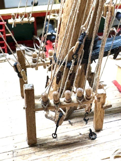
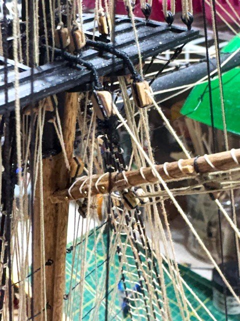
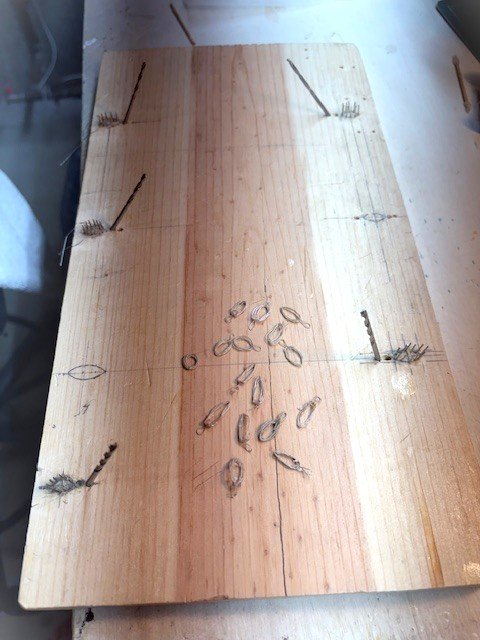
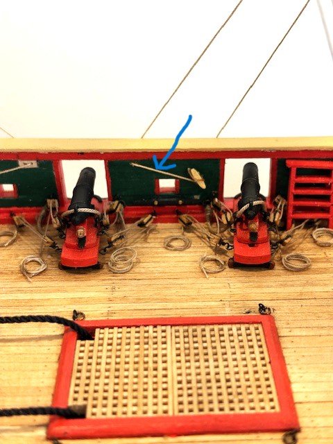
To round out the ship, I've been adding rope hanks (coils) - a slow, tedious process. I follow a video by Tom Lauria on Utube called "Rigging Tips: Making Scale Rope Hanks." I'm not completely satisfied with the results,
.jpg.9520f3264f2889fe904b0903425d55cd.jpg)
.jpg.fa3f60603a08b148bc27016249a47c0d.jpg)
-
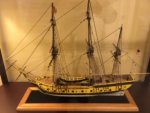
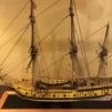
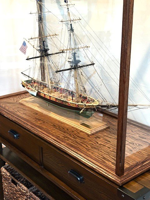
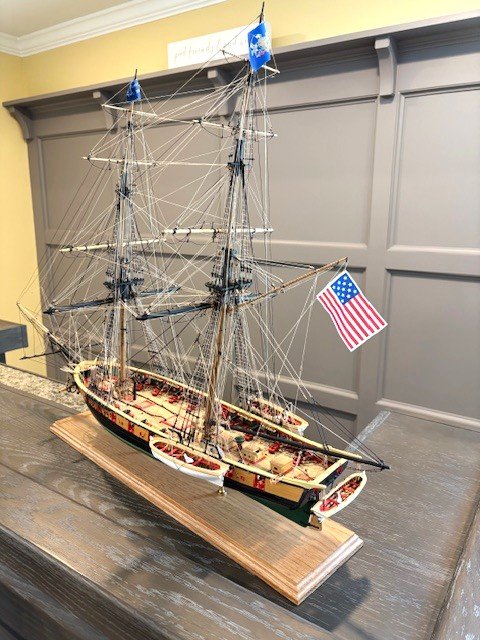
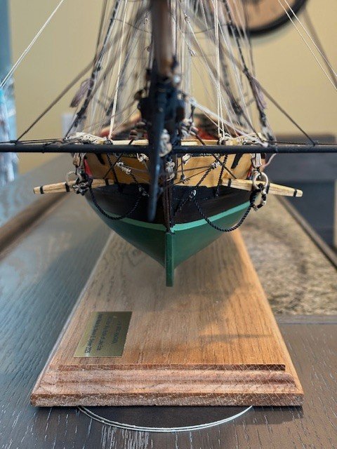
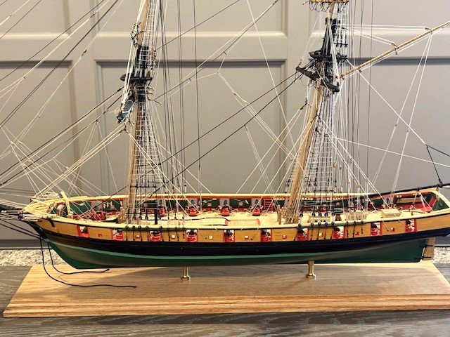
While I still need to make the numerous rope coils, I decided to put the ship in its display case. I ordered a White's Woodworking, Oak Ship Model Display Case, 42”L X 16”W X 32”H from ModelExpo. The kit comes unassembled, and without glass panels. The display case cost $292.88 on sale. The plexiglass was $158.69 from my local Ace Hardware store. The case needs to be sanded, stained and assembled. The total cost ($451.57) was much less than other suppliers such as CaptJimsCargo.com and Abordage.com, which come complete finished and with glass. There are a couple of things that I dislike about the White’s display case: 1. You’re on your own if you don’ t properly measure for the plexiglass panels and 2. The top frame has a narrow, rabbeted groove which makes placing the plexiglass perilous. Note: I beveled the outer edge of each vertical post and finished the case with Minwax Red Mahogany stain and two (2) coats of Minwax polyacrylic clear coat. One more thing, I wish I had cut down the vertical posts before I beveled them - they're too tall for the ship.
.jpg.1814d0b8c45c2a56af4fa62173ee1c91.jpg)
-
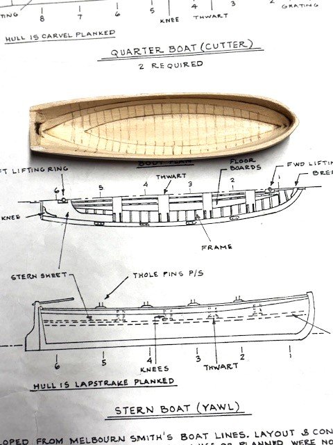
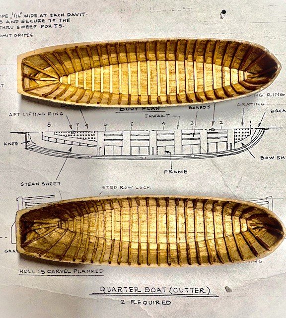
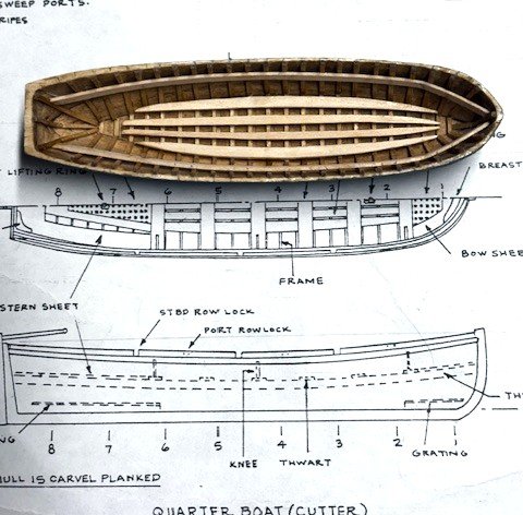
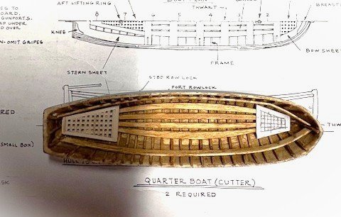
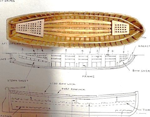
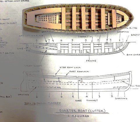
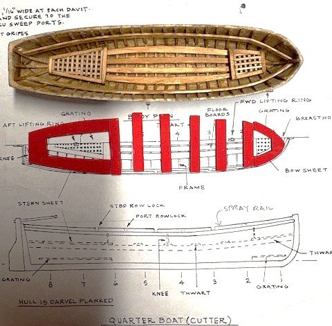
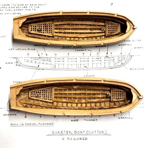
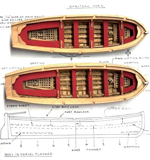
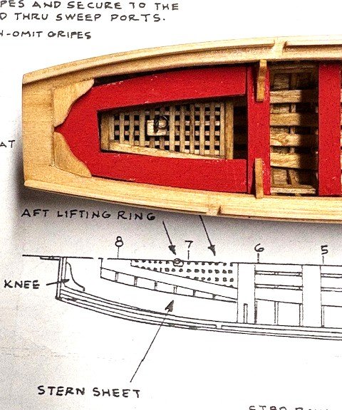
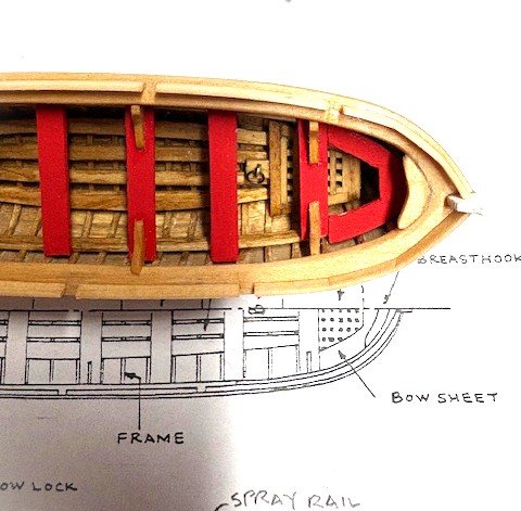
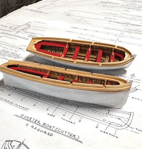
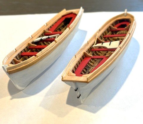
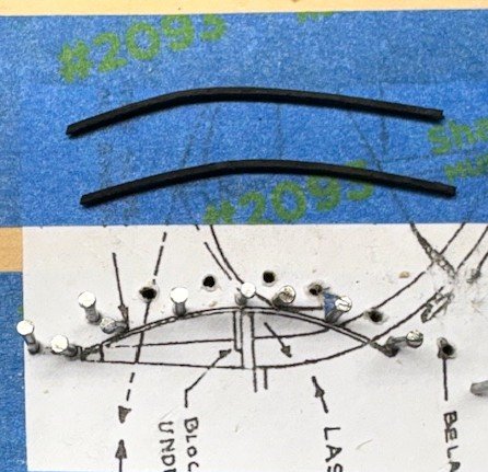
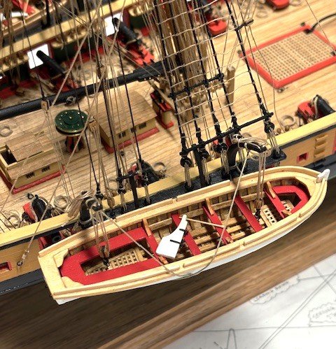
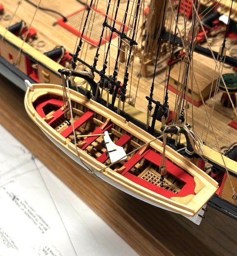
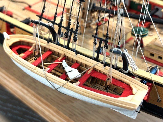
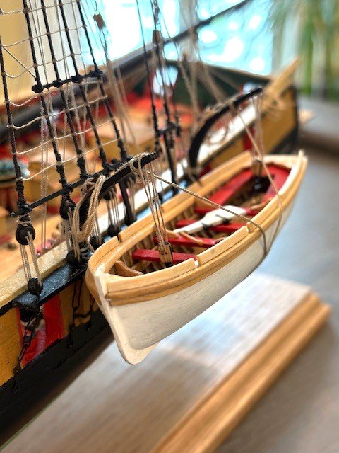
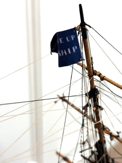
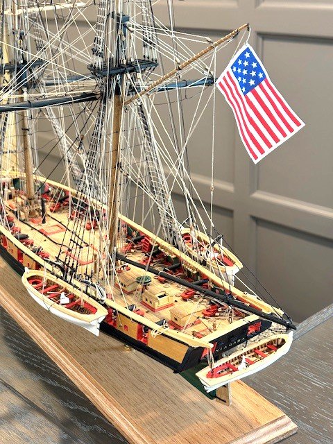
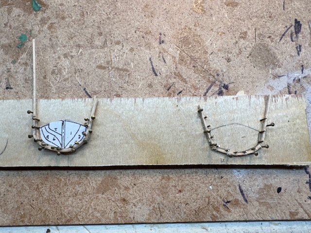
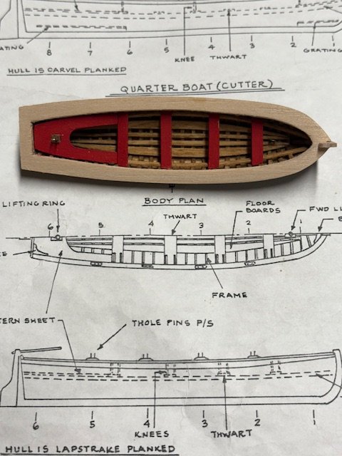
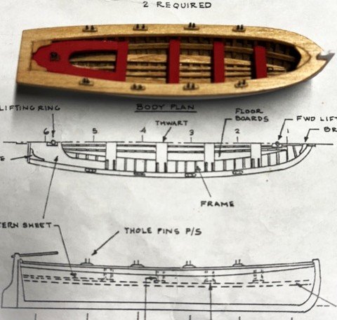
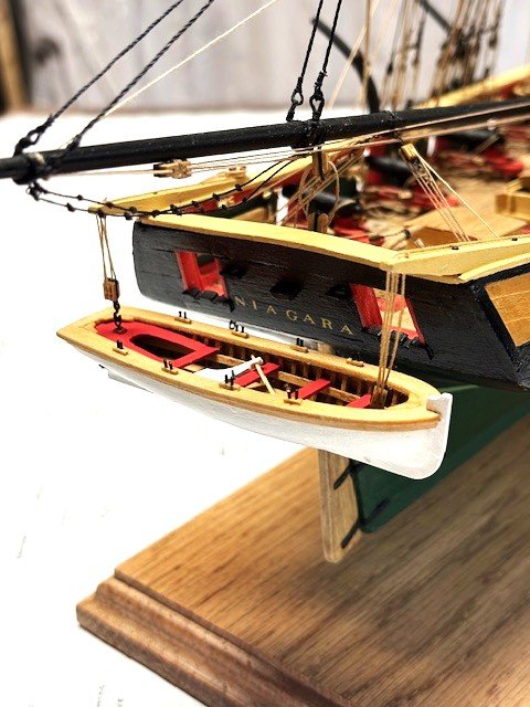
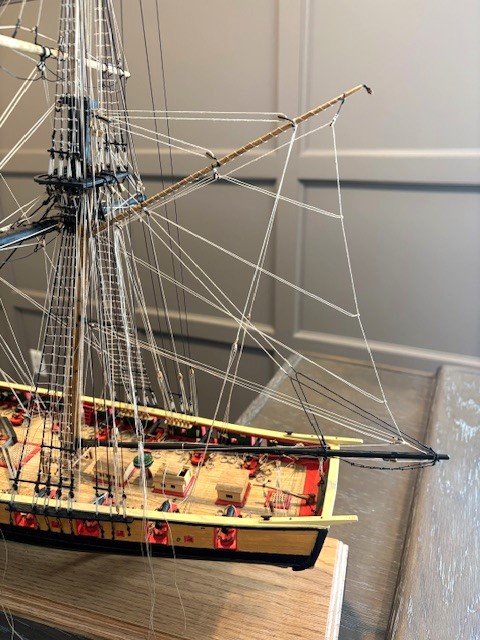
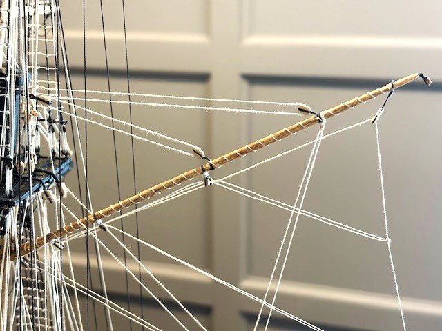
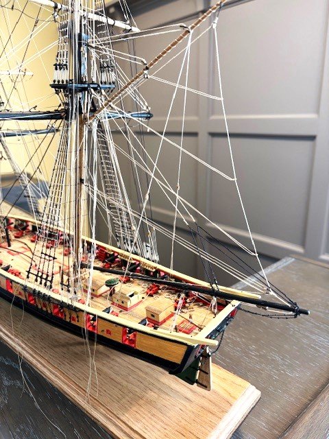
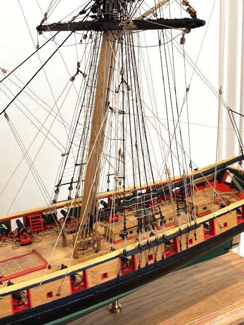
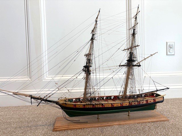
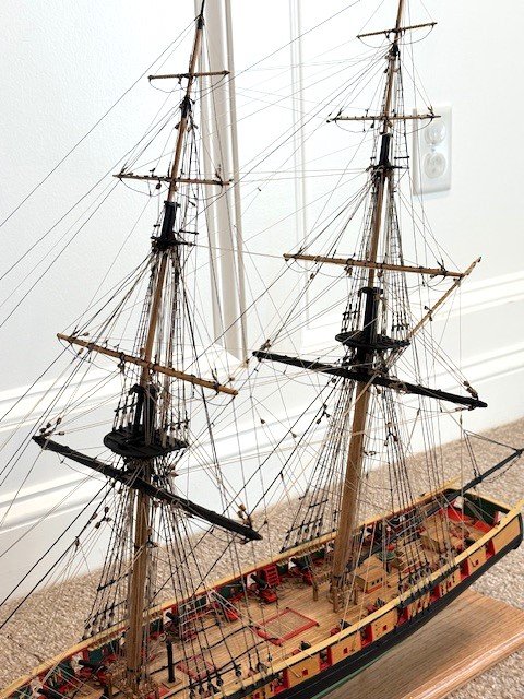
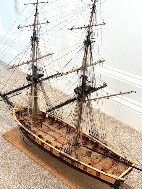
Started fashioning the Quarter Boats (Cutters), which were previously shaped. I followed the same procedures as for the Stern Boat. The frames are the tedious part. Applied a coat of Minwax Pre-Stain Conditioner followed by a coat of Minwax Golden Oak Stain. The floorboards were fashioned a la the Stearn Boat. The thwart supports were added next. I used 3/32” x 1/16” wood strips. The strips were soaked in water overnight and then placed in a jig to bend them (see photo). The grates were next. The Quarter Boat detail seems to show a frame around the grates. I made a template based on the detail and used it to fashion the grates. I pieced together some walnut grating strips in the general size shown on the detail. I applied some AC to the grates to secure them together and then made an angular saw- cut on two sides. I added a 3/32”x 1/8” strip on 4-sides. The grates were finished with Minwax Pre-Stain Conditioner and Minwax Golden Oak Stain. The stern sheet, bow sheet and thwarts were fashioned from 1/8” x 1/32” wood strip and painted (2 coats) with Vallejo Acrylic Paint, Flat Red. The top rail was cut from 3/16” basswood in the same manner as the Stern Boat rail and sanded to achieve the proper overhang for the 1/32" x 1/16" wood molding strip. The rowlocks were cut from 1/32” x 1/16” wood strips soaked in water overnight and formed in the same jig used for the thwart supports. I found it easier to glue the entire strip to the top rail and to then cut out the oarlocks. Note: The locations of the oarlocks are different on the port and starboard sides. With that done, the top rail, trim board, knees, and rowlocks with finished with Minwax Tung Oil. The lifting hooks were added. The stern sheet, bow sheet and thwarts were glued in-place. I decided to make the knees, since there are only six of them. They were glued to the thwarts and finished with tung oil. The rudders were finished next. I added some detail to them. The rudder handle was made from a toothpick that was placed in a Dremel and sanded down to shape. Added the 3/64”x1/64” wood batten slides (painted black). The strips were soaked in water overnight and then set in a jig (see photo) to bend them. Once bent, the strips were easy to install using just CA to secure them. Rigged the 5/32” lifting blocks and tackles (.018” rope) and hung the cutters from the davits. I added the strap grips using .018” rope clove hitched to each davit midway between the cleat and the end sheave. The grips were “criss-crossed” as per the detail on Sheet 4 and secured to the davits. Raised the Pennsylvania State Flag and the "Don't Give Up the Ship" flag (not furnished with the kit). I found the flags on the internet. I copied an image of each flag, reduced to an appropriate scale, printed two images of each flag end-to-end on copy paper, cut them out, and folded them over and glued them together. I inserted a small ring in the top and bottom of each flag at the bend, rigged them to .008" lanyards, and ran the lanyards through a 3/64” block on top of the mainmast and foremast. With that, except for the monotonous task of making numerous rope loops, the ship is complete - 2 years and 10 months in the making. I've added some additional photos.
.jpg.598c4b4da5cf6e914cba5f575ece2791.jpg)
.jpg.73fecc935685a79bf0f1cd19861f89e5.jpg)
.jpg.46bf09b95323fd801f5f5ab65b1bc2dc.jpg)

.jpg.d8fc9d76f688d246652d97bf71d25de6.jpg)
.jpg.d61ec5f2300d82c65f6f3f2ffae3d0c5.jpg)
-
abelson reacted to a post in a topic:
US Brig Niagara by xken - FINISHED - Model Shipways - Scale 1/64
-
abelson reacted to a post in a topic:
US Brig Niagara by xken - FINISHED - Model Shipways - Scale 1/64
-
abelson reacted to a post in a topic:
US Brig Niagara by xken - FINISHED - Model Shipways - Scale 1/64
-
abelson reacted to a post in a topic:
US Brig Niagara by xken - FINISHED - Model Shipways - Scale 1/64
-
abelson reacted to a post in a topic:
US Brig Niagara by xken - FINISHED - Model Shipways - Scale 1/64
-
abelson reacted to a post in a topic:
US Brig Niagara by xken - FINISHED - Model Shipways - Scale 1/64
-
abelson reacted to a post in a topic:
US Brig Niagara by xken - FINISHED - Model Shipways - Scale 1/64
-
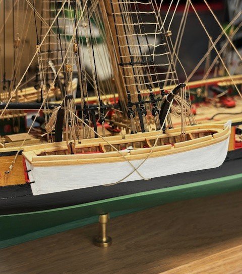
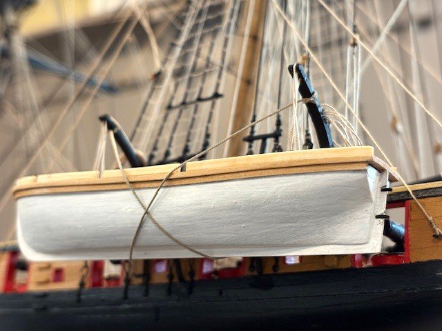
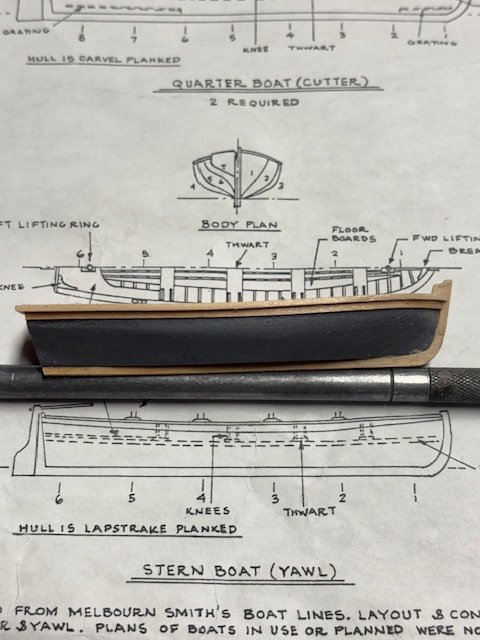
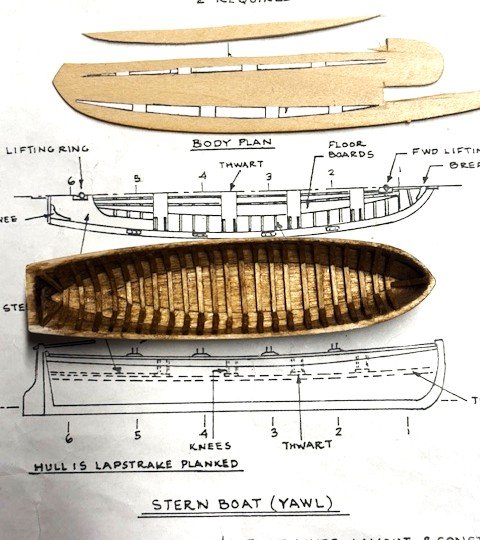
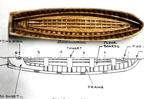
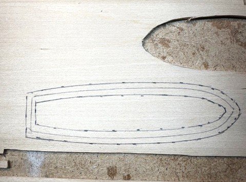
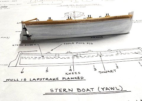
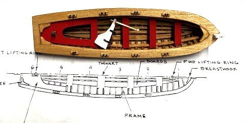
Began finishing the stern boat (yawl) that was pre-shaped early-on in the build. I chose not to lapstrake plank the hull. The inside of the hull needed more shaping before placing the frames. I used some Dramel bits for shaping. I marked the frame locations with a pencil. I used 1/32"x 1/32" wood strips for the frame. I cut pieces for the bottom of the hull. Next, I made a jig for bending the strips. I photocopied the cross-section of the hull from Sheet 4, cut it out and glued it on a piece of wood. I drilled holes intermittently along the profile of the hull and inserted pins. I formed a 1/32"x 1/32" strip that had been soaking in water over night around the pins. I drilled holes on the opposite side of the strip and inserted pins to hold the strip in place. Whence the strips dried, I removed them and cut pieces to complete the frames. As a matter of note, I find the plans lacking in detail relative to the frames. With the frames completed, I applied a coat of Minwax Pre-Stain Conditioner followed by a coat of Minwax Golden Oak Stain. The floorboards were next. I photocopied the floorboards on Sheet 4, cut them out and glued them on a scrap piece if 1/32” wood. I cut out the images with a knife. Sanding was necessary to conform the floorboards to the bottom of the hull. The thwart supports were added next. I used 3/32” x 1/16” wood strip. I found that the strips did not have to be pre-bent. The thwarts and floorboards were finished with Minwax Pre-Stain Conditioner and Minwax Golden Oak Stain. The stern sheet and thwarts were fashioned from 1/8” x 1/32” wood strip. I made the stern sheet in the same manner as the floorboards. As for the lifting rings, I can’t decipher from the stern details whether there is an opening in the stern sheet through which the 5/32” double lifting block is hooked to a lifting hook in the frame or the lifting hook is attached to the stern sheet. Other build logs have attached to the ring to the stern sheet. I’m thinking that it would be very difficult to hook the lifting block to a hook in the frame beneath the stern sheet when the time comes to stow the yawl. So, I decided to attach the hook to the stern sheet. The forward lifting hook is clearly attached to the frame. The stern sheet and the thwarts were painted with Vallejo Acrylic Paint, Flat Red. For the top rail, I used the stern boat as a template. I turned the hull upside down on a sheet of 3/16” basswood and traced around the hull. I then moved the hull on each side of the pencil line about 1/8 of an inch and retraced all the way around again. I cut along the inner and outer lines with an Xacto knife. After several failed attempts, I finally fashioned a top rail that fits the stern boat nearly perfectly. I added a 1/32" x 1/16" wood molding strip to the hull beneath the top rail. The laser cut keel was added next. I cut off the rudder. A piece of the keel broke off at the fore so I had to add a more decorative piece (see photo). BTW, I spray painted the hull with gray primer and finished it with Vallego white acrylic paint. Sheet 4 calls for the top rail and trim board to be painted red. I thought the color would be too much red, so I decided to finish the top rail and trim board with Minwax Tung Oil for more contrast. I used two (2) coats. Added breast hook and aft knees. Opted not to add the thwart knees - too much small, detailed work. The throles were made with 1/32"x 1/32" wood strips and brass pins. To add a little detail to the rudder, I made some rudder brackets from 3/32" x 1/16" brass strip. I rigged the yawl is per the Yawl Stowage on Stern Davits detail on Sheet 4, except I opted to omit the gripes. I used .021” rope. I added a50/50 mixture of yellow glue and water to the rope to stiffen it. I attached clips to the keel to weight it done. The yawl is now complete. Next up, the Quarter Boats.

.jpg.30a936501ae734c970d156fff1eb7860.jpg)
-
Thank you. Your ship is coming along well. Fine work.
-
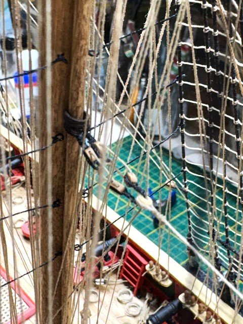
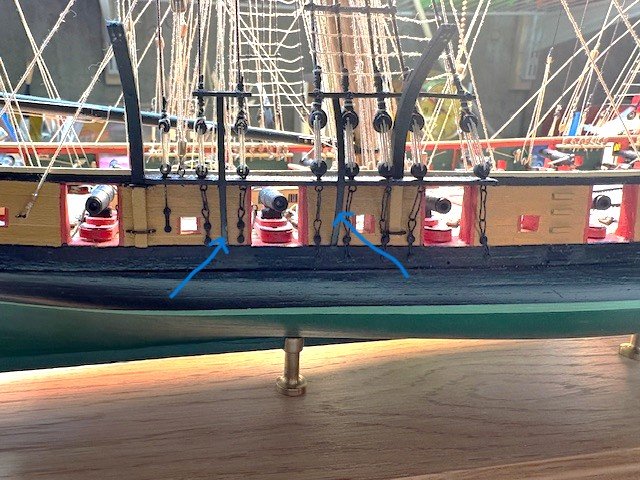
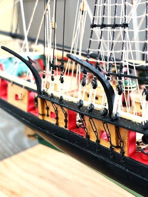
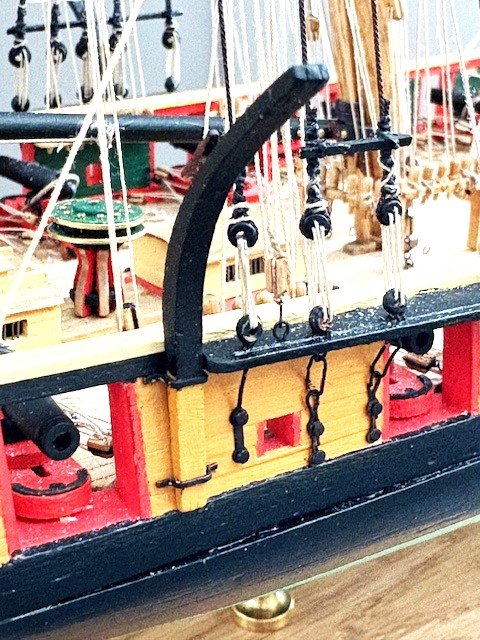
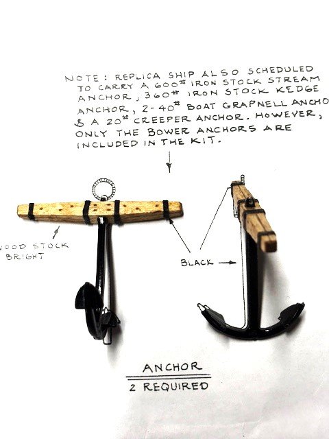
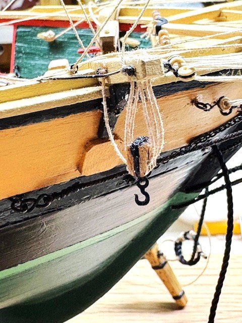
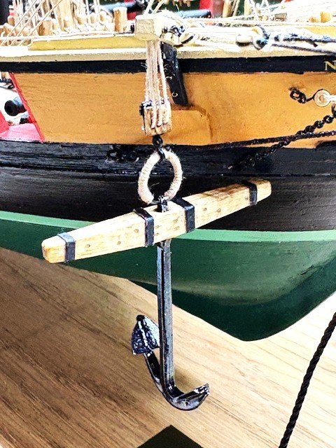
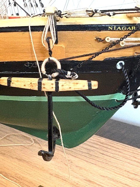
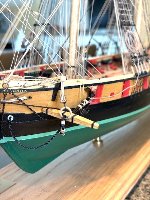
Added the laser cut davits (previously fashioned). The davit brackets were made with 1/64" x 1/32" brass strip, blackened. The batten slides will be added later. I decided to make the anchor stocks. Rather than make them in two halves, I used a single piece of 3/32” x ¼” wood strip. I made a copy of the Anchor detail on Sheet 4, cut out the anchor stock, and used it as a template. The stocks are tapered on three sides (top is flat). I drilled a hole at the midpoint of the stock and squared it up with a file. To simulate treenails, I drilled holes in an alternating pattern and filled them with Golden Oak putty. To simulate stock halves, I scribed a line down the center of the stock with a knife. To finish up the stocks, I applied Golden Oak stain. To simulate the iron bands, I cut a strip from a file folder, marked it with a black Sharpie, and glued individual strips to the stock. I touched them up with black paint. The look of the wood stocks is a huge improvement over the Britanna cast stocks. I cleaned up the anchor castings and finished them with black acrylic paint. The iron rings were made by wrapping 22 -gauge wire around a 1/4” diameter dowel and snipping the ends off. I wrapped rings with .012” tan rope before attaching them to the anchor. Note: Leave a little bit of the ring ends unwrapped so it fits in the anchor hole. Rigging the anchor was next. For the anchor cable (.051” black rope), rather than a simple overhand knot tied to the anchor ring, I added a little more detail following a detail that I found somewhere (don’t recall where). See photo. For stropping the anchor tackle I used .012” tan rope. I tied a Syren plastic hook to the rope and then stropped a 5/32” triple block. The tackle was made .018” tan rope and is reeved through the faux sheaves at the end of the cat head as per the Anchor Stowage detail on Sheet 4. I hooked the ring to the anchor ring and attached some clips to the anchor to weight it down. I then applied a 50/550 mixture of yellow carpenter glue and water to the rope to stiffen it. I cut a length of .018” tan rope long enough to attach it to the anchor and to the shrouds. The rope is seized to the anchor with .012” rope. I coiled the anchor rope and tied it to the fore mast shrouds. The ship is basically complete except for finishing the quarter boats and the stern boat.
.jpg.4ceea23f375d5676d88416b676a69c20.jpg)
.jpg.55885cfcca8cba3de63bd0facc3785d2.jpg)
.jpg.c75ba509d841d2139ed02eca4a991b10.jpg)
-
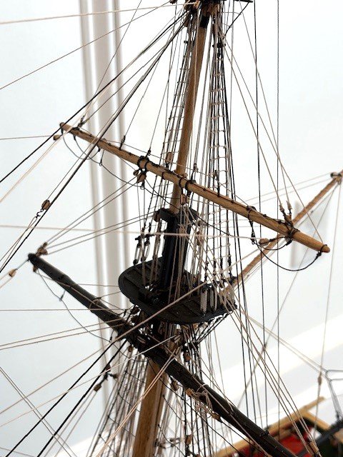
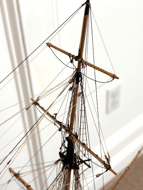
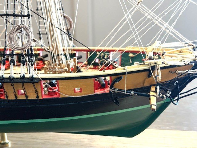
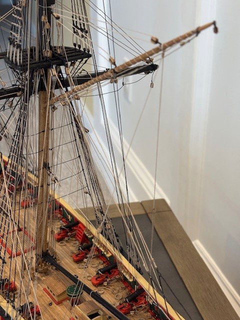
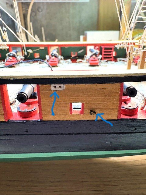
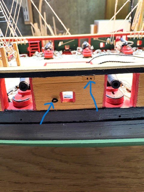
I’ve completed all the rigging at this point. What follows is the sequence of completion: The Spanker Gaff Throat Halliard as per Detail 5-J on Sheet 5. I used .018" tan rope (plan calls for .016"). The Peak Halliard with .018" tan rope (plan calls for .016"). Belayed to pin 65 S. The Vangs. I used .018" tan rope for the pendant and .012" tan rope for the falls which are belayed to cleat 75 P&S. The Spanker Sail Brails P&S. I had added the required blocks to the gaff so I thought I might as well add the brails (See photos). This was an arduous task. In hindsight, having to do it again, I would only rig the brails attached to the clew outhaul. My plan was to show the brails as they would appear with the spanker sail furled. One thing that I discovered (I might be wrong here), the shoe block as shown on Sheet 5 is incorrect. The position of the shoe block would be as if the spanker sail was furled, but the brails are shown as if the sail is unfurled. Basically, the shoe block would have to be much further back along the spanker boom so that, when the spanker sail is furled, the brail can be pulled forward to furl the sail. As I planned, the following photos depict the brails as they would appear when the sail is furled. The brails are belayed to shared pins 51 P&S and 52 P&S. The spanker tack tackle was rigged with a 1/8" single block and a .012" rope. The bottom block is hooked to a deck eye bolt. The tackle is belayed to a cleat on the port side of the fife rail bitt as shown in Detail 5-K and called out on Page 35 in the Instruction Manual. The most difficult part was belaying the rope to the fife pins. In so doing, I snagged the bunt lines which pulled out the double block beneath the main top -UGH. I had to redo the bunt lines. It was impossible to reinsert the eyebolt, so I drilled a hole in the top, passed a length of 24-gauge wire through it, looped the end through the lash on the block, and then pulled the wire up, trimmed the wire and bent it over. One thing that I have come to expect in model ship building is Murphy’s Law: "Anything that can go wrong will go wrong.” In hindsight, I would not have added the brails. Next, the Main Course Yard Sheets, Clew, and Tack. Note: Sheet 6 says the main course yard sheets, clew, and tack are usually not used. These lines are rigged together in a block assembly same as the fore course yard. I used the kit supplied .021” rope. The standing end of clew line is seized around the yard rather than above the clew block on the yard as shown and noted on Sheet 6. The course sheets are seized to the eyebolt on the bulwark between gun ports 9 &10, pass through the assembly block and then through the bulwark sheave and belayed to cleat 76 P&S. Of further note, Sheet 6 calls for the fore course tack block to be hooked to any convenient spot on the fore channels but doesn’t say where the tack is belayed. A followed 6ohiocav’s build log for the main course yard tack, i.e., I added an eye bolt and a faux sheave in the hull between gun port 5 and 6, and a cleat inside the bulwarks to belay the tack. Continuing, the various braces as Shown on Detail 6-A. I had previously added all of the blocks except for the two blocks seized to the topgallant shrouds “close to the hounds.” It’s important to study this detail early-on in the ship building process. Note: I used .018” rope where the detail calls for .016, .012” rope where the plan calls for .014”, and .008” where the plan calls for .008” rope. The most difficult part of the braces was belaying them to the various pins. Though this is my fourth build, I still have difficulty belaying rope to the pins. In some cases, I just belayed some ropes to the top mast shear poles. To the novice eye this won’t be noticeable. Next up, boat davits, anchors, and quarter boats.
.jpg.671d66ce97a7af1c9b2fa545e38d1360.jpg)
.jpg.384e96dc7aaac162dd358b2835180932.jpg)
.jpg.35c1dbdef68c2680adaa31da92fd5be1.jpg)
.jpg.a03760bdf0e189a2f98086eef811791e.jpg)
.jpg.6da2ed999fa3a99e14a5475a9ad336f1.jpg)