

abelson
-
Posts
467 -
Joined
-
Last visited
Content Type
Profiles
Forums
Gallery
Events
Everything posted by abelson
-
 Nice work on the blocks and hooks. I've skipped that work for now, but what gauge wire did you use for the hooks?
- 950 replies
-
- 1
-

-
- syren
- model shipways
- (and 1 more)
-
Thanks so much.
-
Thanks for the compliment and encouragement. This has been an enjoyable build with varying levels of difficulty.
- 157 replies
-
- 2
-
-
- model shipways
- syren
- (and 1 more)
-
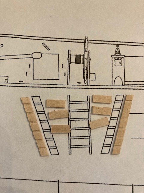
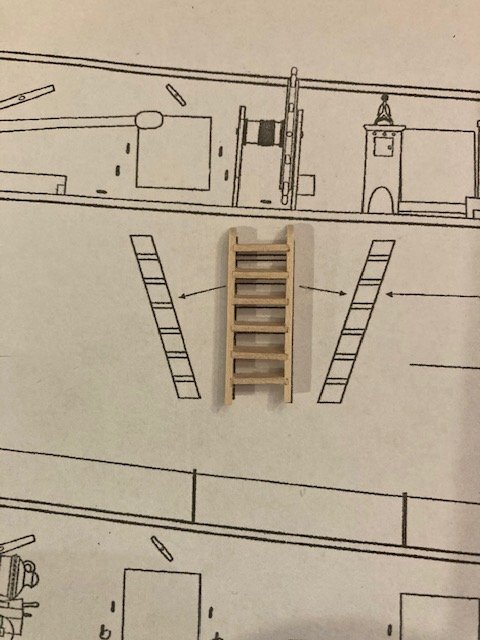
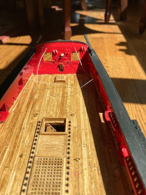
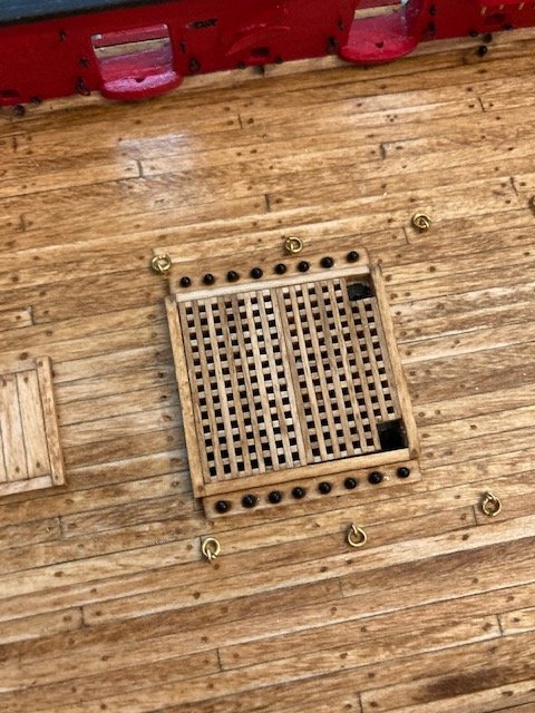
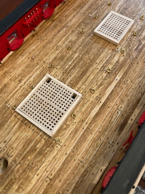
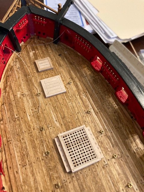
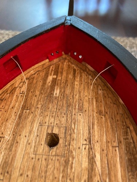
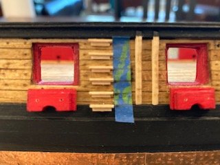
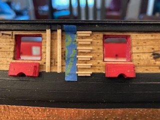
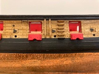
Moving on to the companionway. I installed the edge boards around the inside of the companionway. The companionway ladder side rails and steps were made from 1/32”x 1/8” wood strips as per the instructions. I used the detail on Sheet 4 as a guide for marking the steps. Using a knife, I made a vertical cut along each step line. Turning the strip on its side, I made a cut between the two vertical cuts along the midpoint of the strip. I removed the notch with a small square file and then evened the grooves (notches) using a flat file that has teeth on the edges. The steps were then glued in place. I filed the ladder to square up all the edges and rounded the top of the side rails. The ladder was stained and glued in the companionway. I decided to sand the coamings to conform to the camber of the deck. The camber is very slight. I stained the hatchways and shot racks. At the mid ship hatch, I drilled a hole in the deck at each location for passing anchor cable through the hatch grating. After that, I glued the cannon balls to the divots with CA and then glued the hatchways and shot racks to the deck with white glue. The hatches are now finished. At this point, I’m going to get some of the easier deck fittings out of the way. So, I’ll be holding the capstan and binnacle in abeyance and jumping ahead to Chapter 13 again. Stay tuned.
- 157 replies
-
- 6
-
-
- model shipways
- syren
- (and 1 more)
-
Thanks for the compliment. I'll probably glue the gratings and coamings in-place and hold off on the other deck fittings. Right now, I'm enjoying fabricating the deck fittings. At some point, I'll get around to the rigging.
- 157 replies
-
- 2
-
-
- model shipways
- syren
- (and 1 more)
-
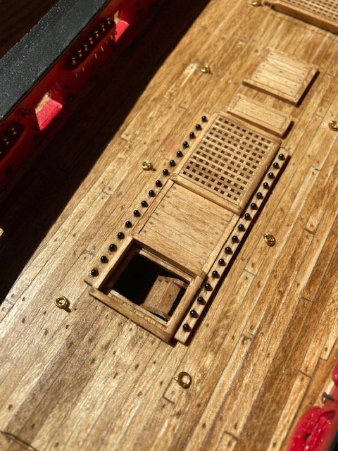
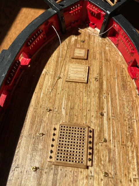
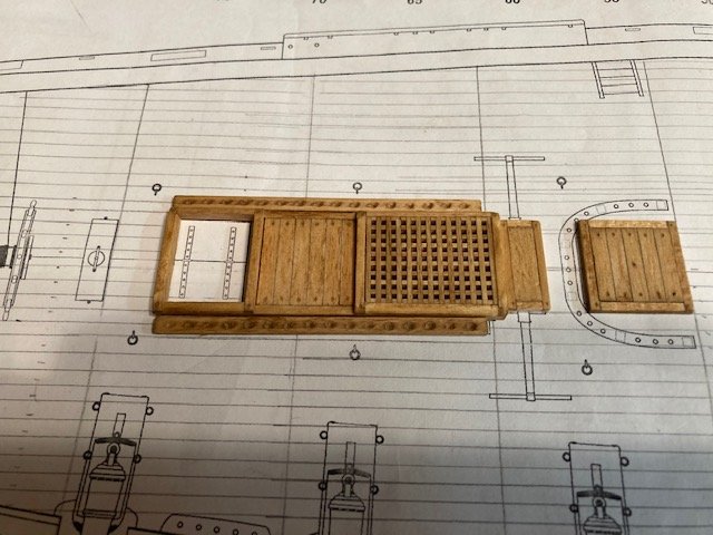
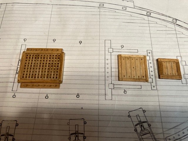
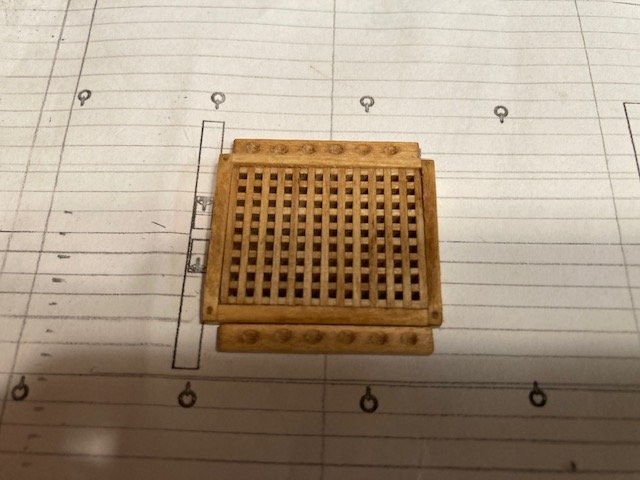
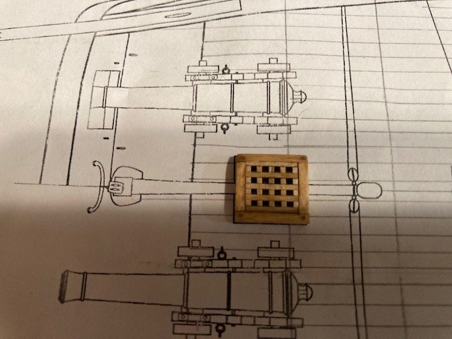
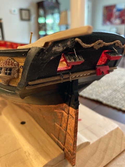
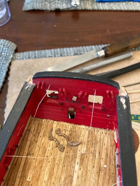
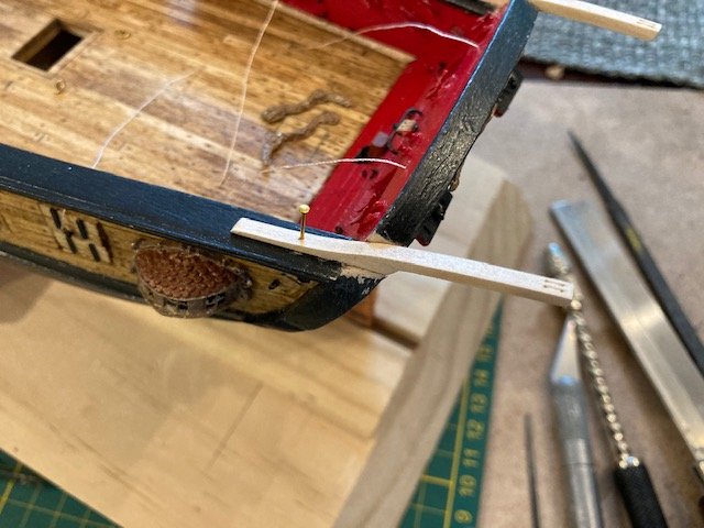
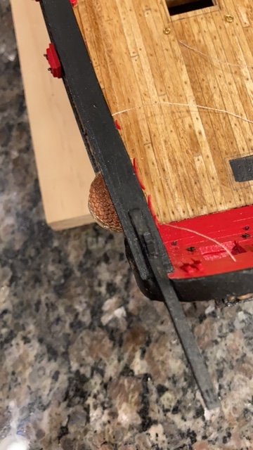
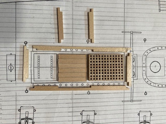
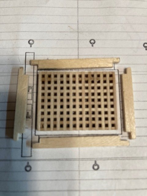
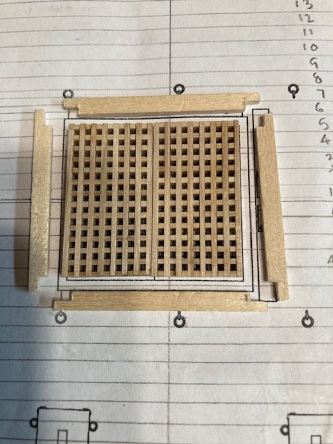
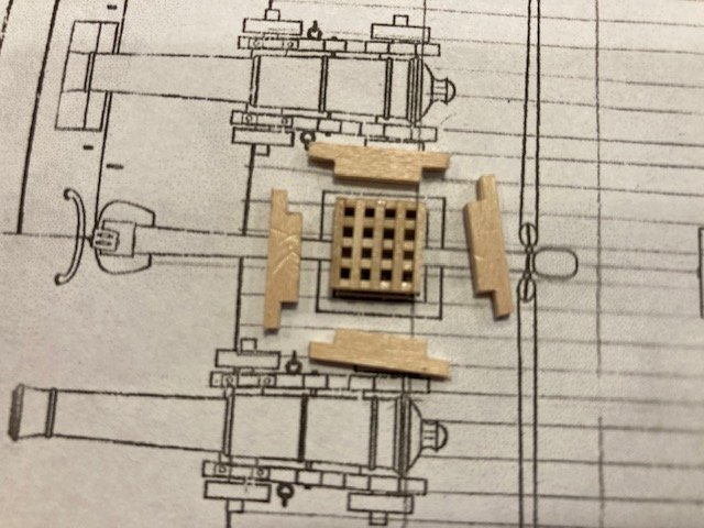
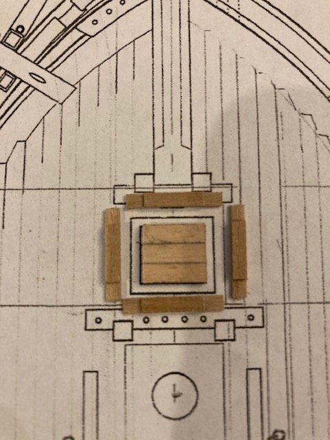
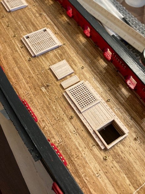
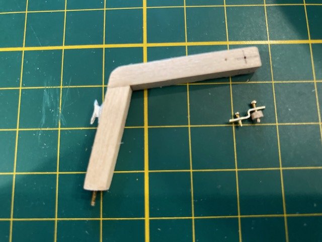
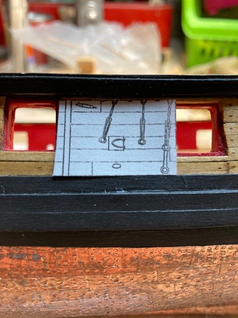
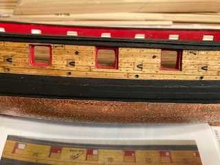
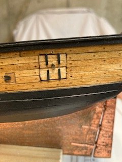
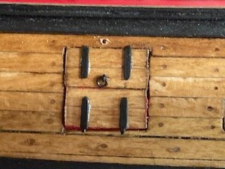
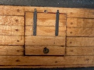
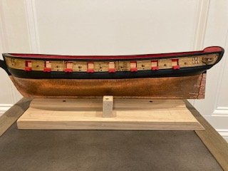
Before getting into rigging the carronades, I jumped ahead to Chapter 14 and installed the stern davits. I removed the char from the laser cut pieces and made the faux sheaves in each piece. I drilled a hole at the location of the 5 mm cleat for insertion of a pin to secure the davit to the rail. The port side of the transom was carefully notched out with an x-acto knife as per the instructions. I had to remove ("deconstruct") the metal carvings above the stern ports to accommodate the notch. I confidently notched the starboard side of the transom with a saw (less work than using a knife). I evened out the edges of the notch with a file. The davits fit well without the need for wood filler. I wasn’t sure how to finish off the transom cap rail. I decided to leave the top edge square and to round off the bottom edge. I glued the davits and then painted them and the transom. The cleat was added to each davit. The cleat is 5 mm boxwood Syren cleat that I had left over from my Fair American build. The metal carvings were re-glued. The davits extend precariously beyond the stern, so I’ll have to be careful not to break them off. I’m holding off on rigging the carronades, so I Jumped ahead to Chapter 12 to start the deck fittings. I find this chapter to be enjoyable - it's constructive and you can see your accomplishments with each deck fitting completion. I made all the grating pieces for the hatches. I had read in another build log that the top grates run fore and aft. This is contrary to the plans and the instructions which clearly show that the top grates run port to starboard or perpendicular the centerline of the ship. The only exception to this is the smaller scuttle at the stern. I decided to follow the plans. Before cutting off the excess grating tabs, I applied CA to the back side of the grating. I cut the tabs off with miter saw. After cutting the tabs, the edges were evened out by filing/sanding. Next, I made the coamings for the hatches using 1/8”x 1/16” strips. The corners of the coamings were formed with a lap joint. I notched the joints using a miter saw and a knife. I made a vertical cut to the center line of the coaming strip with the saw and then cut a horizontal line with a knife. After all the coamings were fabricated, I assembled them. I squared up the coamings with the grates and glued them one at a time with CA. I sanded the bottom of the coamings to create a camber for the coamings to sit properly on the deck. The boards that the capstan will sit on were made from 1/8”x 1/16” strips, as per the instructions. To emphasize the seams between the boards, I ran a pencil along edge of each strip. I’m not sure whether to sand the tops of the hatches to match the camber, for fair that I might ruin them – the jury’s still out. Note: I notice in some build logs that a wood strip was placed between the two grates at the midship. The plans do not depict this, so I opted to stick with the plans. I fabricated the shot racks from 1/8”x 1/16” strips. I cut out the shot rack from the plan and used it as a template to mark the locations of the divots. The difficult part here was creating a divot or dimple for the cannon balls. I used a 1.5 mm drill bit. I sanded each divot with the corner edge of folded 100 grit piece of sandpaper. To create a ledge for the companionway, I still need to add 1/32” x 1/8” strips around the inside edge of the open hatch. I made the platform for the pumps as per the instructions and, jumping ahead to Chapter 13, I made the raised platforms for the galley stack and at each mast. All of the deck fittings are temporarily placed on the deck and will be stained with Minwax Golden Oak. Next up, the capstan, companionway ladder, and binnacle – not necessarily in that order.

.jpg.288e17f6bc796d8a8b836863d637ae25.jpg)
.jpg.5b1700c836f25eea175fcc0e696f88ae.jpg)
- 157 replies
-
- 7
-
-
- model shipways
- syren
- (and 1 more)
-
Thanks for the words of encouragement. I'm currently working on the davits. It requires some "deconstruction."
- 157 replies
-
- 2
-
-
- model shipways
- syren
- (and 1 more)
-
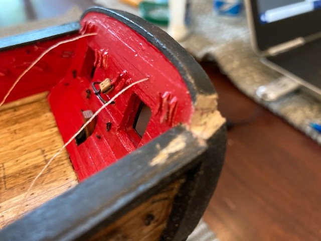
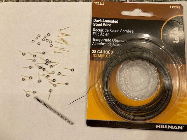
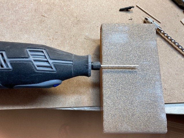
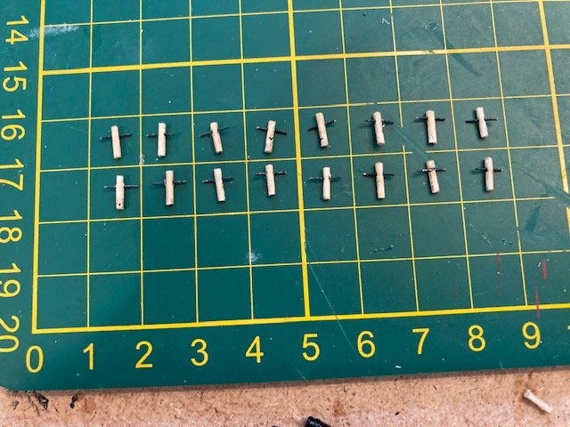
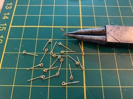
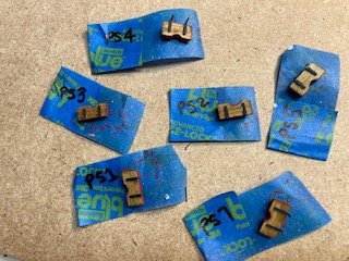
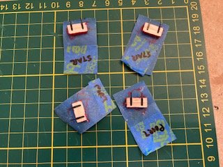
Just a brief progress update. I found the lost carronade. It was wedged between the seat and the back of my dining room chair – Phew. Also, I received the replacement 8 mm brass belaying pins from Model Expo. I inserted them temporarily in the pin rails. I like the look of them as is, but I do plan to blacken them. Continuing with the build, I glued the eye bolts for the tackles. One frustration here was that the brass black flakes off the eye bolts, so I have to touch them up with paint. I made the split rings for the breach line eye bolts from 28 gauge wire (furnished with the kit) coiled tightly around a 1.5 mm drill bit. I cut the individual rings from the coil with a nail clipper. I closed the rings with a sharp-nosed pair of pliers and then attached them to the 1/32” eye bolts furnished with the kit. I found it easier to open the eye on the bolt, attach the ring and then close the eye. I attached these temporarily to the bulwarks. They will be glued after the breach lines are seized to them. I went ahead and made the split rings for the deck in the same fashion. These where made from 20-gauge brass wire (not furnished) and 1/16” eyebolts (not furnished). I used a deck template to mark the locations of the 22 rings. I drilled a .55 mm hole for each ring, and temporarily inserted the eye bolts. These will be blackened and permanently glued in-place. Stay tuned for more.
.jpg.bf549e89e08a48d8f7c9e4908c6ca6fa.jpg)
- 157 replies
-
- 8
-
-
- model shipways
- syren
- (and 1 more)
-
Nice work on the pin rails. Good idea on using the scrap wood for setting the rails at the same height. Wish i had thought of that.
- 950 replies
-
- 1
-
-
- syren
- model shipways
- (and 1 more)
-
Yes, thanks for the compliment. I've been struggling with eye bolts and split rings for the breach lines. I have them in temporarily now. I need to install the eye bolts for the lower gun tackles. I'll be glad when this work is done.
- 157 replies
-
- 2
-
-
- model shipways
- syren
- (and 1 more)
-
This is good info, thanks for posting. It would be a significant investment in rope. I'm at the carronade rigging stage, but have not yet begun. I want to experiment with the kit supplied nylon line before considering Syren rope. BTY, the ship is looking good - nice sharp detail.
-
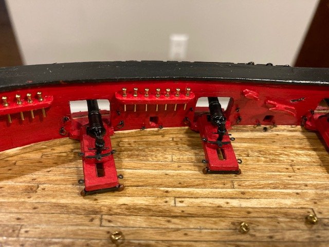
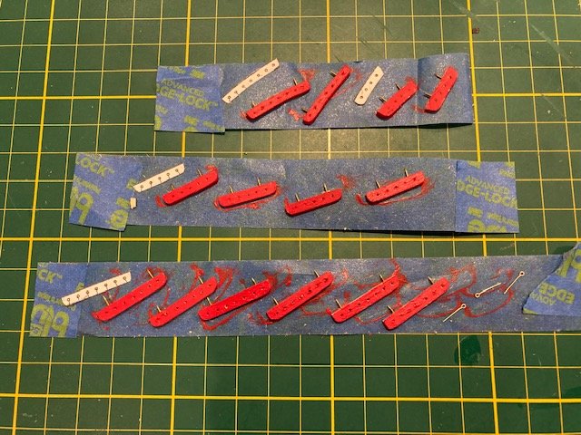
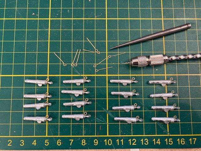
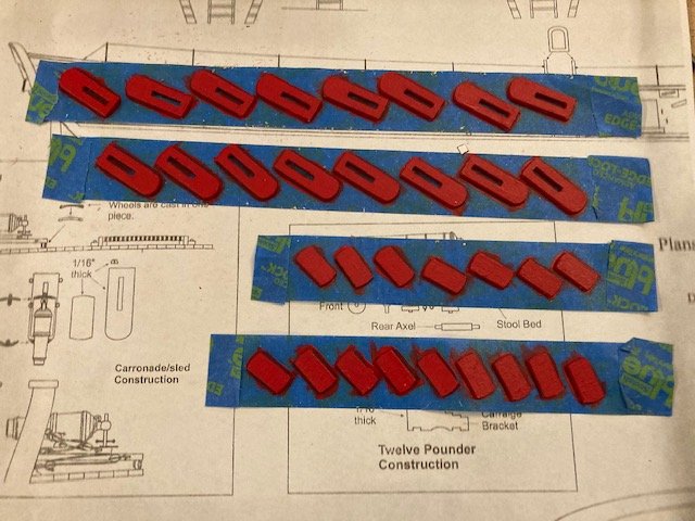
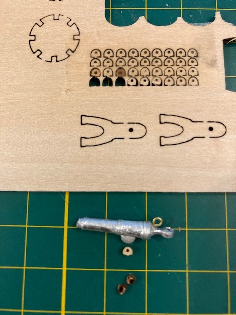
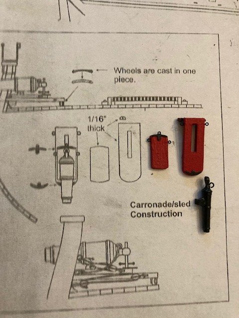
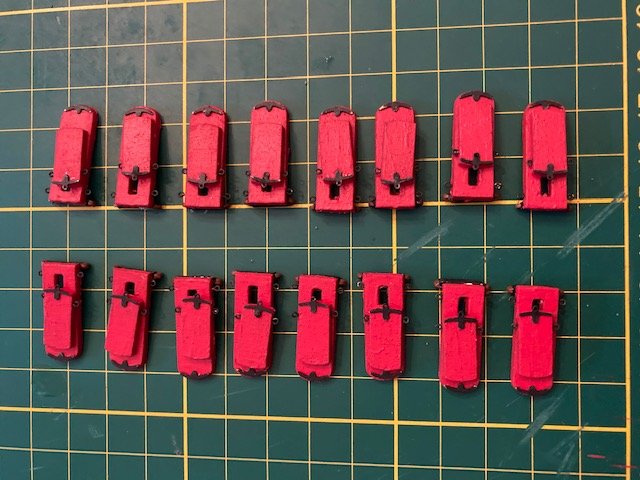
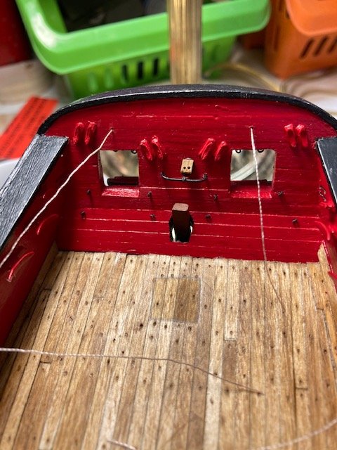
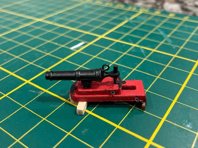
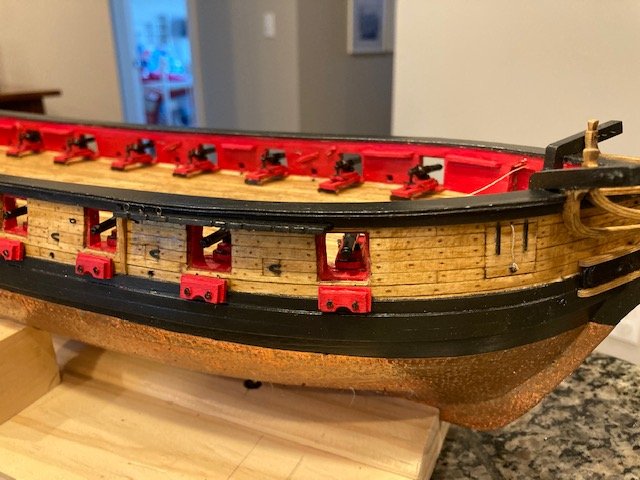
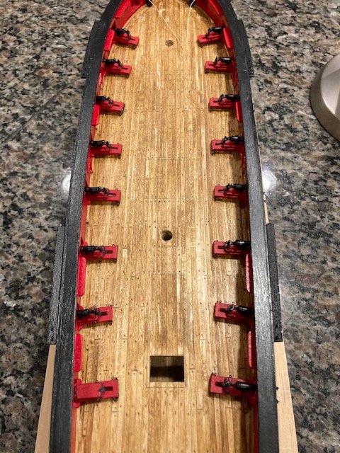
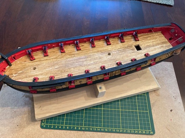
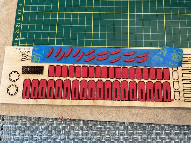
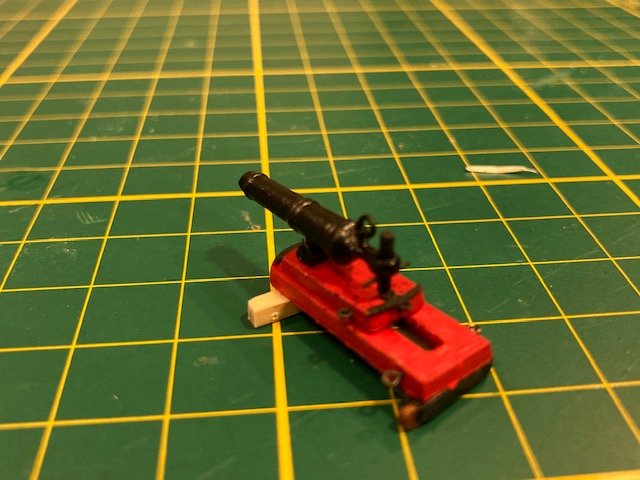
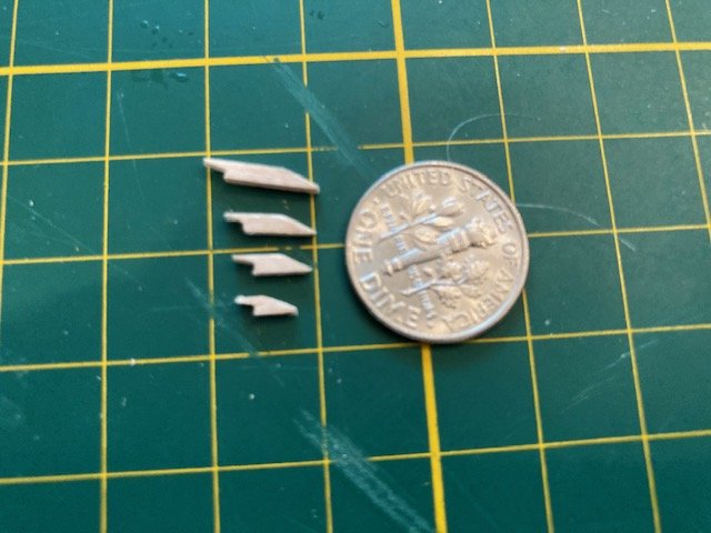
Moving on to Chapter 11, I had previously marked the locations of hatches and masts on the deck using a template, so I was one step ahead of the instructions. To get the location of the inboard cleats, eye bolts, and pin rails, I made a photocopy of sections of the bulwarks elevation and cut out the ports, cleats, and pin rails. I placed them over the gun ports and then marked the locations of eye bolts with an awl and the locations of cleats and pin channels with a pencil. I drilled a 0.55 mm hole at each eye bolt location for inserting the eye bolts. I cleaned up the 5mm and 10mm cast cleats. I used white glue to attach them to the bulwarks at the pre-marked locations. I later applied CA with a toothpick to secure them to the bulwarks, and painted them red. Next, I removed the laser cut carronade swivel brackets, removed the char, and painted them red before gluing them in-place. I only painted the exposed side of the brackets. I decide to paint the carronade sled components before removing them from the laser cut board (WP4638-G). I will remove these and sand off the char from the edges later. For the pin rails, I used 1/16” x 5/32” basswood strips instead of 1/16” x 1/8”. The extra width gives some allowance for sanding and shaping. For the pin rails, I cut out the corresponding pin rail from the drawing and used it as a template to get the end shape and the location of holes for the belaying pins. My kit came with 8 mm walnut belaying pins. These were a substitute for 8 mm brass pins, due to lack of availability. Before drilling holes in the pin rails, I did a test fit of the 8 mm walnut pins. The walnut pins are larger than brass pins which results in them being too close together on the pin rail (see photo). I’m waiting for Model Expo to replace the walnut pins with brass pins. In the meantime, I drilled holes in the pin rails to accommodate the 8 mm brass belaying pins. BTY, 8 mm is approximately 5/16”. The pin rails on the drawings scale about 13/32” which corresponds with a 10 mm belaying pin. Model Expo does not carry 10 mm brass pins. I also drilled two holes in the side of each pin rail for the insertion of brass pins to secure the rails to the bulwarks. After pin rails and swivel brackets were installed, I gave the entire inboard bulwarks another coat of paint followed by a coat of Minwax Polyurethane. I’m not happy with the finish on the pin rails – the grain of the boxwood doesn’t provide for a smooth finish. Finished up the inboard bulwarks by stropping the double block to the traveler. Constructing the Carronades: Note: The instructions say to drill a hole in the cast carronade for the iron ring for the breach lines. This is not an easy task. The holes must be drilled at an angle. The metal casting is not that soft and, consequently, the drill bit tends to drift. I made a pilot hole first with an awl and then drilled the hole – this alleviated the drift. I used a 0.55 mm bit. The instructions don’t say what size eye bolt to use. The eye bolts that come with the kit (1/32”) are too small. I used 1/16” eye bolts. I glued the eye bolts with CA. Before spray painting the carronades black, I glued the 1/16” laser cut brackets to the carronade lug. The laser cut brackets were all but obliterated on one side, making it difficult to glue them to the lug – there’s no flat surface to adhere to. I persevered, though, and got it done – UGH! After painting the sleds, I blackened the photo-etched sled details and glued them to each sled. I spray painted the sled wheels and, when dry, glued them onto the lower sled component. I used white glue. After the glued dried, I applied CA to the backside of the wheels to secure them. I used toothpicks for the carronade elevating screws. I turned the toothpicks to a size that fit through the ring on the carronade using my Dremel and a sanding block (100 grit). I made the screws 3/16” long. I was able to make 4 or 5 screws from one toothpick. I marked the length of the screws on the toothpick. I drilled a hole in each screw for the elevating the screw handle. I found it easier to drill the holes before, rather than after, turning the toothpick. In the process, I also found that the toothpicks break at the drill holes if too much pressure is applied in the turning practice. Patience is a virtue here. To simulate the handle of the elevation screw, I inserted a piece of scrap shank from shortened eye bolts. I spray painted the screw assemblies black. Next, I glued the two sled pieces together. I test fit one sled, holding the carronade in position to see how it aligns with the port opening. The difficult part here is gluing the carronade to the sled while maintaining the elevation of the carronade in the port and I also aligning the carronade so the elevation screw will be positioned directly over the photo etched plate. I found it easier to align the carronade screw by inserting it in the carronade before, rather than after, gluing the carronade. Thereafter, I glued the rest of the carronades using the first one as a guide. I wasn’t concerned about each carronade being aligned exactly in the center of the ports because they probably weren’t on the actual ship. Surprisingly, they were all fairly centered in the ports. I’m holding off on gluing the sleds to the deck until I figure out the rigging. In the meantime, I applied a coat of Minwax polyurethane on the deck. I misplaced one finished carronade. If it doesn't show up, I'll have to see if Model Expo will replace it. Stay tuned for report on lost carronade.
.jpg.28edd55ea5400ce37865b8aa90cfcea1.jpg)

- 157 replies
-
- 6
-
-
- model shipways
- syren
- (and 1 more)
-
Nice work on the head timbers. And, they're perpendicular to the keel.
- 950 replies
-
- 1
-
-
- syren
- model shipways
- (and 1 more)
-
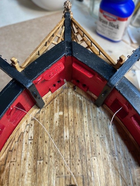
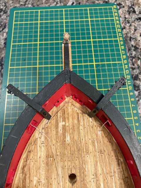
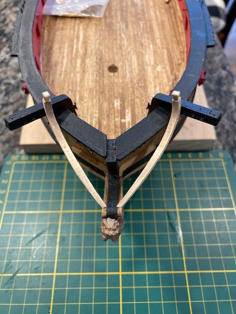
Completed the head timbers - phew! The upper head timbers were more challenging than the lower head timbers. I made notches in the timbers to seat on the middle rail. This made it easier to set the timbers. I used white glue. I set each timber in-place with the ship upright and then turned the ship over so that I could align each timber with the lower timber before the glue dried. To secure them, I applied a little CA at the interface of the timber and the bottom of the head rail. Some sanding was required to thin/taper the underside of the timbers. I’m totally pleased with how the head timbers turned out. Except for installing the bumpkins, this completes Chapter 10. So far so good. Now, it’s on to Chapter 11.
- 157 replies
-
- 6
-
-
- model shipways
- syren
- (and 1 more)
-
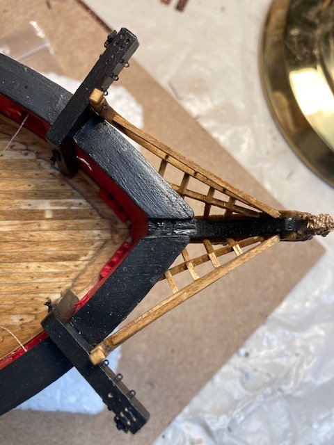
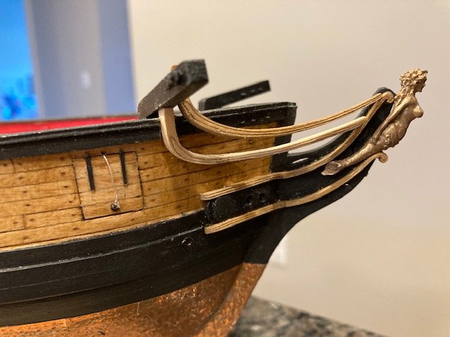
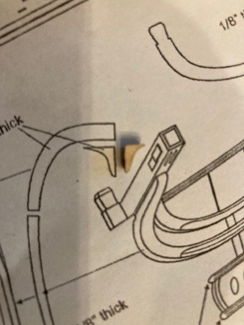
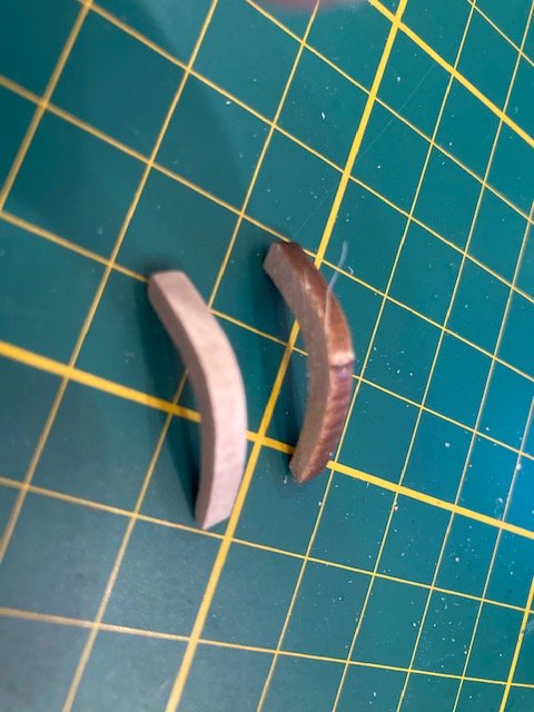
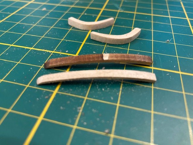
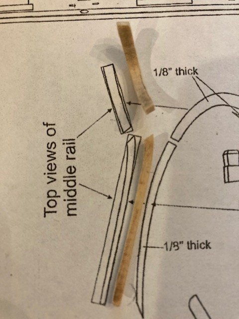
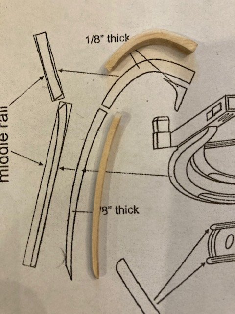
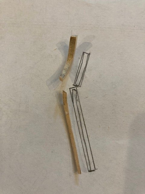
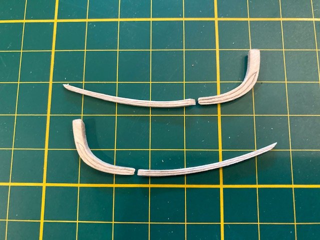
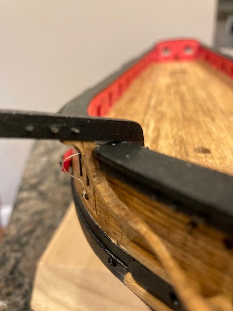
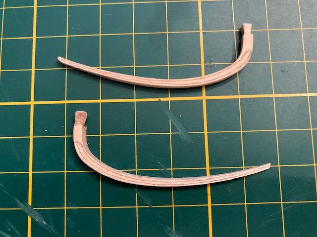
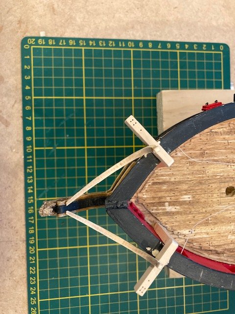
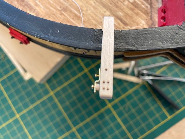
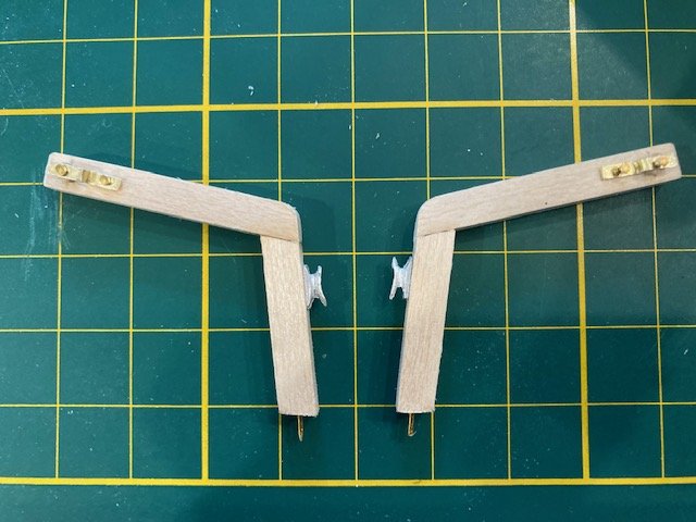
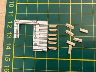
Moving on to the middle rails. I decided to holdoff on installing the upper rails until I complete the middle rails. I notched the overhang of the cap rail and the shear strake to make room for the middle rail. This would have been easier without the catheads in-place, but I didn’t want to do the notching beforehand for fear that the catheads would not be in the proper locations. The laser cut middle rail pieces have a lot of char that is difficult to remove and, in the process, a loss of material thickness occurs (see before and after photos). I shaped Piece #1 and Piece# 2 per the detail on Sheet 4. The detail only shows the starboard side middle rail pieces. The port side pieces are difficult to carve without a detail of the port side pieces. I don’t have a light table, so I placed the detail face down against a windowpane and traced the outline. This gave me a good guide for carving the port side Piece #1 and Piece #2. I was able to carve the decorative grooves in Piece #1 and Piece #2. Piece #2 was angled at the top to seat against the underside of the cathead. I decided the best way to install the middle rail was to glue the pieces together and to then glue the complete rail on the ship. I used white glue to join the two pieces. After the glue dried completely, I added CA glue to the joint on the underside and back of the middle rail. This allowed me to sand the joint to make a smooth transition between the pieces. I do think the rail is too thin, though. So, I decided to do them over. I made a template of Piece #1, glued it on the 1/8” sheet of basswood, and cut it out with a jeweler’s saw. The second go-around is slightly better (see before and after photos). The last part of the middle rail is the laser cut Piece #3, the hanging knee under the cathead. These pieces are very small, and slightly smaller than the same piece on the detail (see photos). Removing the char made them even smaller. Piece #3 was by far the most frustrating part of the head rails. It’s very difficult to shape Piece #3 to fit the width of Piece #2 and the angles formed between Piece #2 and the cathead. Between this and dropping the piece at least a dozen times (UGH!), I don’t know which was more frustrating. There not perfect, but I’m satisfied with how they look. I jumped head to Step 5 and fabricated the top rails and the stanchions as per the instructions. I did this because I was concerned with aligning the stanchions and drilling the holes in the middle rail with rail in-place. I thought it would be easier to do this with the middle rail off ship, and it was. I was able to fit the top rail to the middle rail after several iterations of cutting the stanchions to length. I test fit the assembly – it looks good (see photo). Next, I made the bumpkins. The instructions say to make the bumpkins from 1/16” dowel. The kit does not include a 1/16” dowel. I used the kit supplied 5/64” dowel. It’s a little larger than 1/16”, but not that significant to the naked eye. I drilled a hole in the hull for inserting the bumpkin. Moving on to the head timbers. I fit the head timbers between the cheek and the middle rail. They’re a little difficult to make because of the angles involved, but I managed to cut, trim, and position them to fit. I'm satisfied with the way it came out, but the timbers are not perpendicular to the keel as the drawing shows. Next up, the head timbers between the middle rail and the upper rail.
.jpg.e8e5163b4ed8952e49445b3209a71dc3.jpg)
- 157 replies
-
- 3
-
-
- model shipways
- syren
- (and 1 more)
-
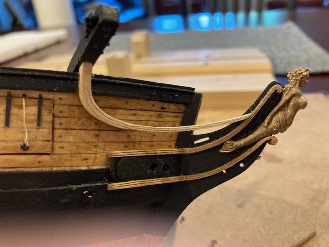
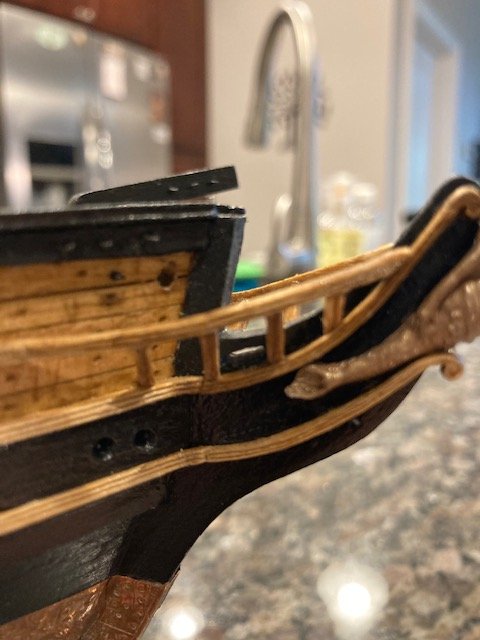
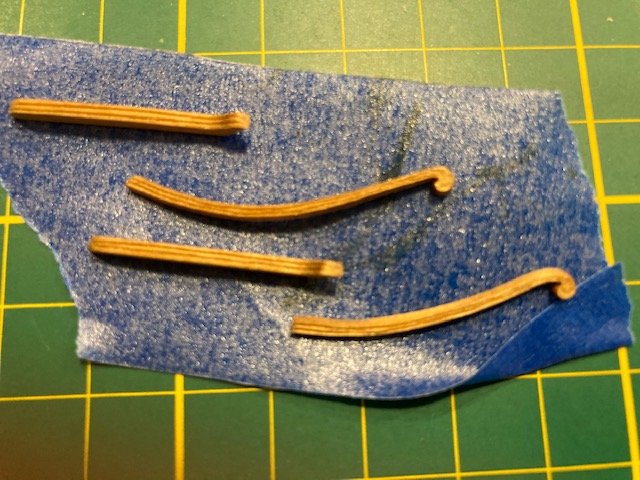
Completed the upper rails. I managed to carve the grooves as per the instructions. On these, I marked the grooves lightly with a mechanical pencil first. This depressed the wood slightly and provided a guide for the knife blade – and my eyes - when I scored the groove. I then traced the groove with my awl. Slow and steady wins the race here. The tops of the rails were filed to create the timberhead. To get the length of the upper rails, I measured 3/8” from the bridle port along the cap rail and made a pencil mark. I trimmed the upper rail accordingly and tapered the end to 1/16”. I stained them Golden Oak. I’m holding off on gluing the upper rails in-place until I fabricate the catheads. The catheads scale slightly larger than 1/8” on Sheet 8. I used 3/16” x 3/16” basswood strip instead of 1/8” x 1/8”. This gave me a little more space for the sheaves and to sand down the cathead pieces. Made the catheads in two pieces. I marked the location of the catheads on the top rail with a strip of masking tape the same width as the cathead. Before cutting out the cap rail and the waterway, I test fit the upper rails. Satisfied with the fit, I cut out the cap rail and the waterway. For the sheaves, I drilled four holes with a #67 (.0320"/.831 mm ) drill bit. I created faux sheaves by scoring the wood between the holes a la the bulwarks sheaves. The sheave for the cathead stopper cable was made with a 1/64” x 3/32” brass strip that I had left over from my Fair American build. The length was approximated based on Sheet 1. I punched holes in the brass strip with an awl and then drilled out the hole with a pin vise. The small disc to simulate the sheave was made from a 1/16” dowel that was sanded down to a diameter slightly greater than 1/64”. I used brass pins to attach the sheave. I filed down the pin heads to make them smaller. Three 1/32” eye bolts were glued into pre-drilled holes along the forward edge of each cathead. I pinned the two cathead pieces together and inserted a pin in the bottom of the cathead where it attaches to the deck. I added a 5mm cast cleat to each cathead. Before gluing the catheads, I added the cleat on the inboard side of each cathead. The catheads look good but, unfortunately, some of the detail will be lost when they are painted black. As check, I test fit the upper rails again. Next up the middle rails.
.jpg.776603369a94cdcc03bcdac39215845f.jpg)
- 157 replies
-
- 4
-
-
- model shipways
- syren
- (and 1 more)
-
Thank you. The perfectionist in me says they could be cleaner.The volutes were difficult - such a small radius. I'm satisfied, though. The stain makes them stand out.
-
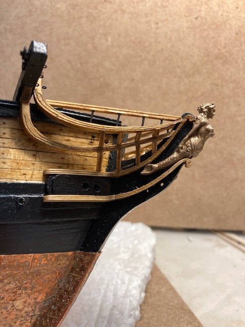
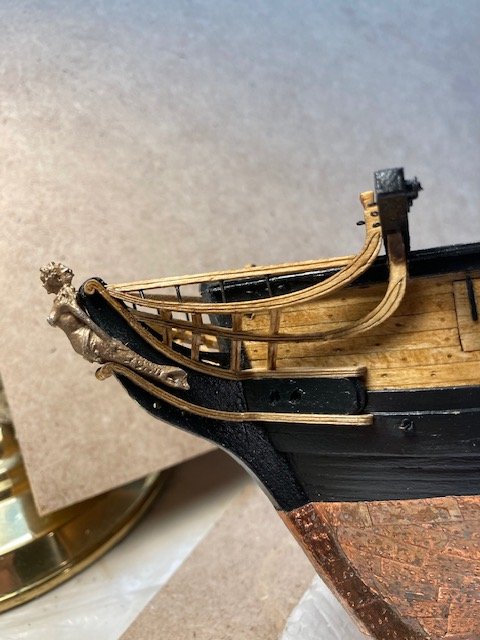
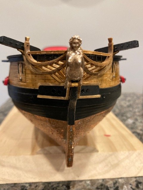
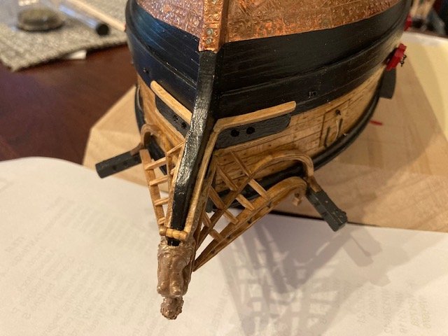
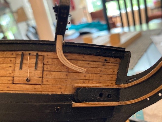
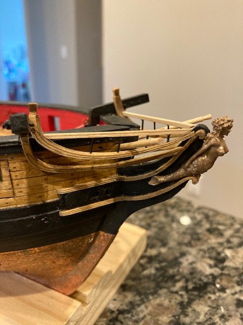
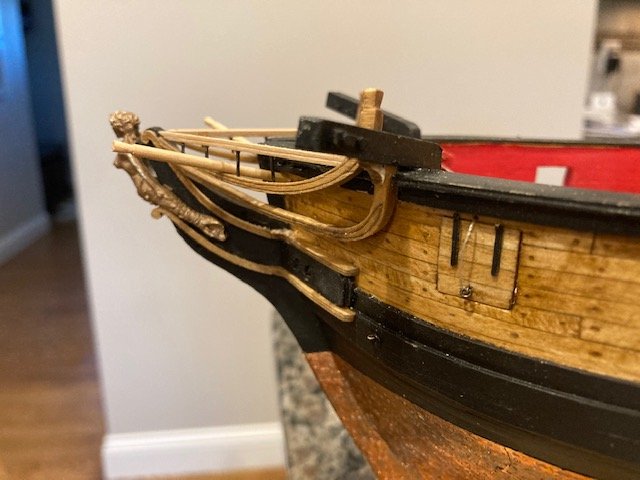
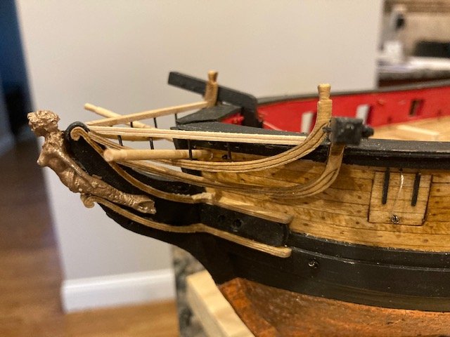
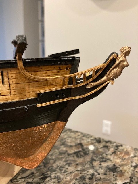
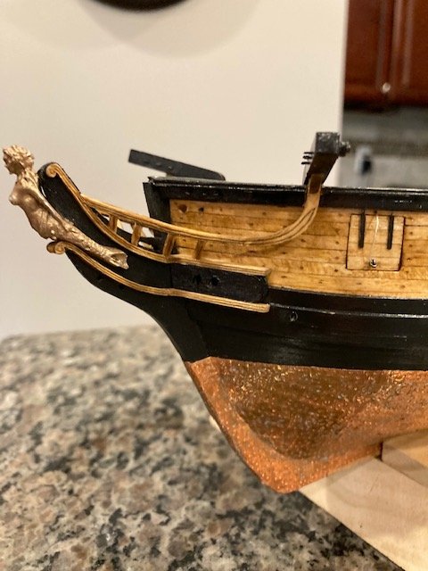
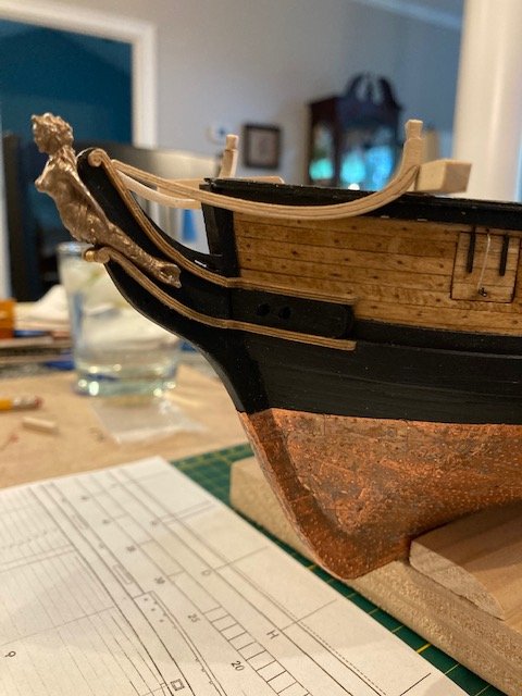
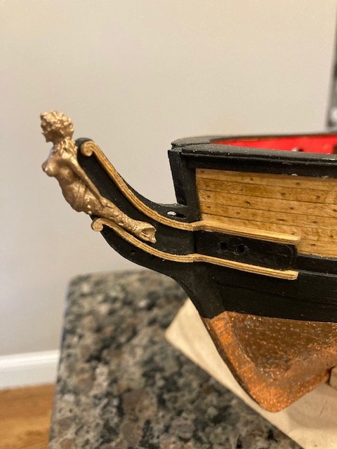
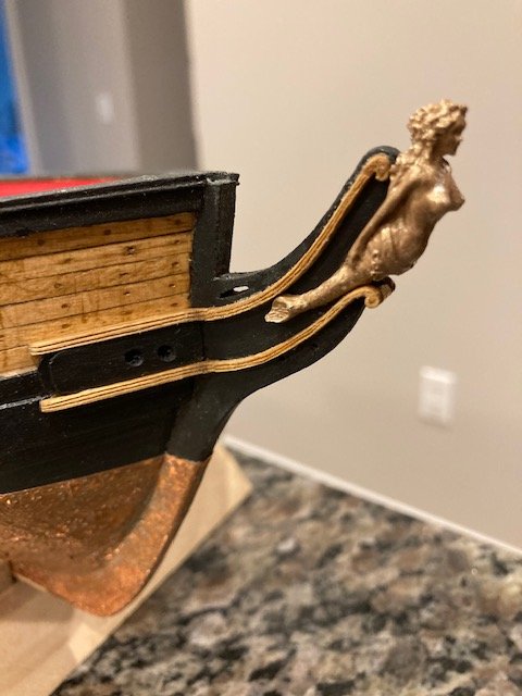
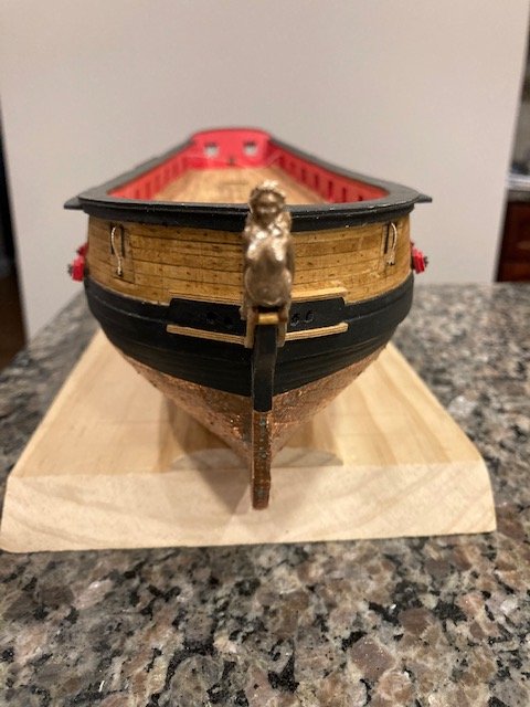
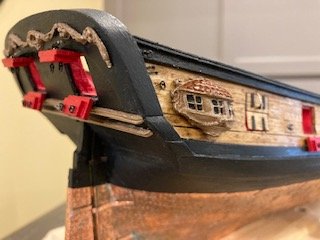
Removed the laser cut cheeks from the 1/16” sheet of basswood (WP4638F) and sanded them to remove char. Test fit them on the stem knee. I was hesitant to carve the two grooves into the cheeks, but they came out fairly well. I scored each cheek with sharp x-acto blade. I needed 5X magnifier to see what I was doing. Per the instructions, using an awl, I traced each scored line several times. I ran the straight edge of #200 sandpaper along the groove to remove some of wood fiber. It’s very difficult to carve the grooves without wondering off when you trace the score, particularly where the cheeks thin out at the volute. It’s important to get a clean continuous cut when you first score the wood - not easy, slow and steady works well. This helps to prevent the awl from wandering off when you trace the score. There not perfect, but I'm happy with how they turned out. The photos tend to show the imperfections. On the model, to the naked eye, I the imperfections aren’t that noticeable. I did the port side cheeks first, stained them, and glued them in-place. I test fit the figure head (painted antique gold) and left it temporarily in-place while I glued the cheeks. This gave me a good guide for placing the cheeks. I think drilling the hawes pipes ahead of time made it easier to install the cheeks – I didn’t have to worry about damaging the them. The starboard side cheeks came out equally as well. Note, the lower cheek volutes are extended beyond the knee stem. The space between them was filled with a piece of toothpick that was stained. Next up, the upper rails.
- 157 replies
-
- 6
-
-
- model shipways
- syren
- (and 1 more)
-
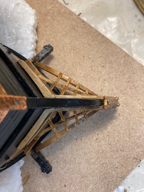
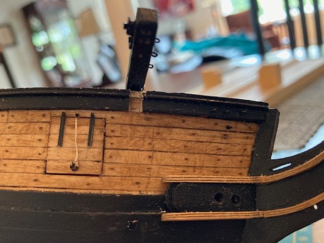
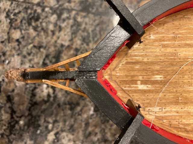
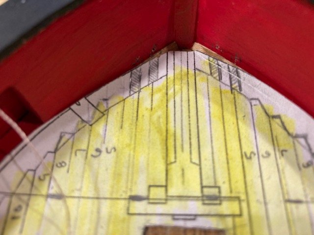
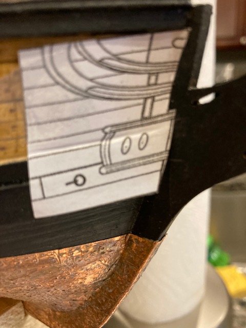
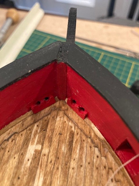
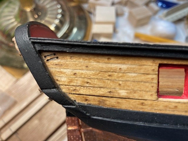
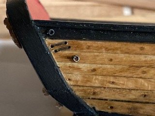
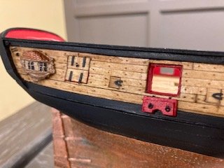
Chapter 10 - Head Rails and Figurehead. My last post was too long, so I decided to make this post short. OK, the location of the hawes pipes concerned me, so I wanted to hit it head on. This chapter is lacking in photos illustrating the inboard hawes pipes, and there is no detailed drawing on the plans. The plan on Sheet 8 shows the hawes pipes as dashed lines. They’re approximately 12” center-to-center at a 3/16” scale. I traced the location of the hawes pipes onto a photocopy of the deck plan that I used for the deck planking. I placed the photocopy on the deck and then marked the location of the hawes pipes on the bulwarks. I measured the distance from the deck to the center of the hawes pipes from the section view on Sheet 8, marked it on the bulwarks, and made a punch mark with my awl. To get the location of the hawes pipes on the outboard side, I made a photocopy of the bow from Sheet 1, cut it out and taped it onto the starboard side bulwarks. I marked the location of the cheeks with a pencil and punched a hole at the center of the hawes pipes with my awl. At the same time, I marked the location of the eye bolt on each side of the bow. I reversed the photocopy and did the same on the port side. This gave me an approximation of where the hawes pipes will be on the outboard and inboard sides. I measured the distance from the inboard punch marks to the top of the rail cap and the distance from the punch marks on the outboard side to the top of the rail cap. I found that there is approximately ¼” vertical separation between the inboard hawes pipe locations and the outboard hawes pipe locations. I’m not sure if this is correct- I may have marked the inboard holes too high. So, as the instructions say, the hawes pipes will have to be drilled at an angle -no easy fete. For starters, I drilled 0.55 mm pilot holes parallel to the keel and at an angle on the inboard side and the outboard side. The difficulty with drilling the holes was trying to get them lined up. I got them to match up, so I went out on a limb and drilled the holes completely through with a 1/16” bit - success. Drilling chewed up the bulwarks a bit -AGH! Note: The section view on Sheet 8 shows a decorative piece around the inboard hawes pipes (like an escutcheon), about which there is no discussion in the instructions. I have seen this on other build logs, so I added this feature. I decided to install the two layers of wood that are glued between the two cheeks prior to installing the cheeks. The layers were made from the 1/32” laser-cut basswood sheet WP4602-H. I like the way it turned out, although the port side is slightly higher than the starboard side. I won’t do it over. I think I can tweak the starboard side cheek slightly to give it an illusion of being level with the port side. Next up. the cheeks.
- 157 replies
-
- 3
-
-
- model shipways
- syren
- (and 1 more)
-
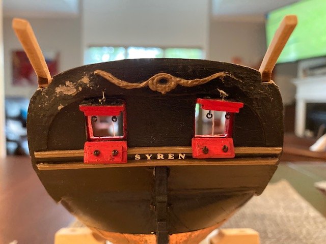
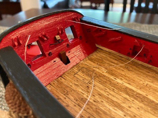
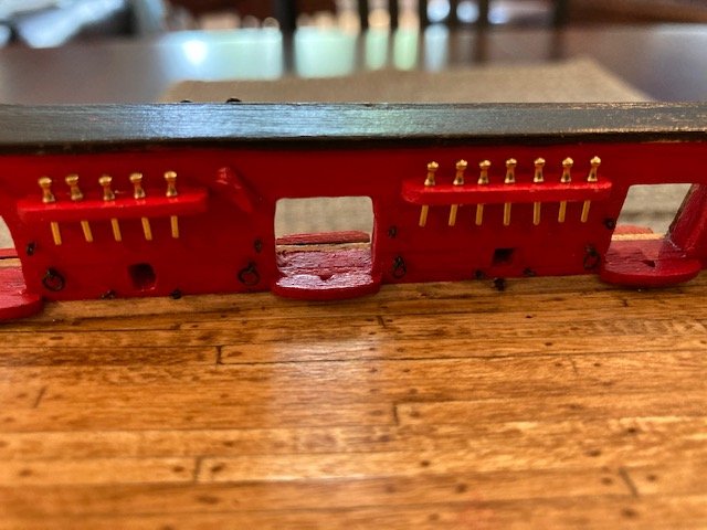
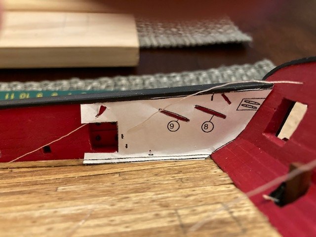
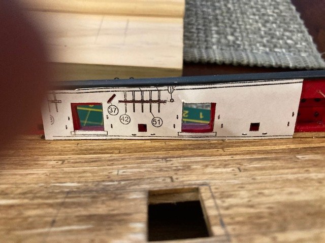
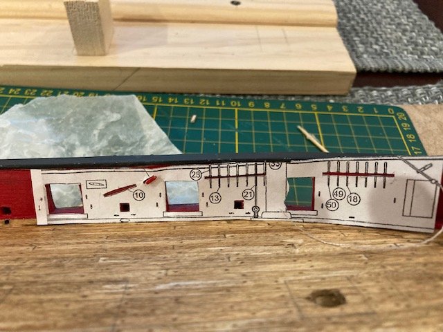
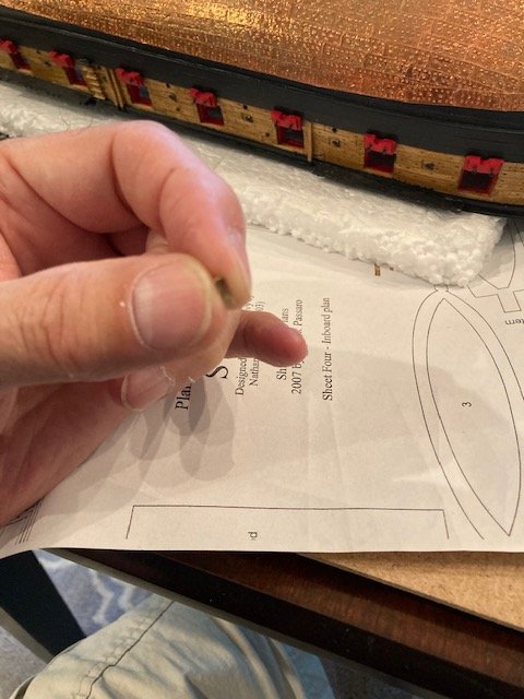
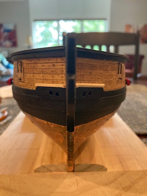
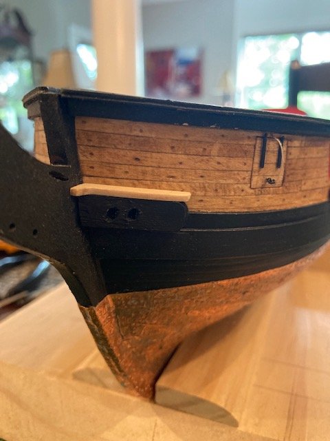
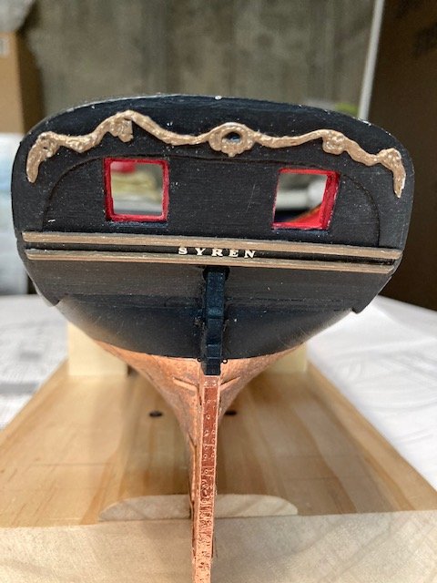
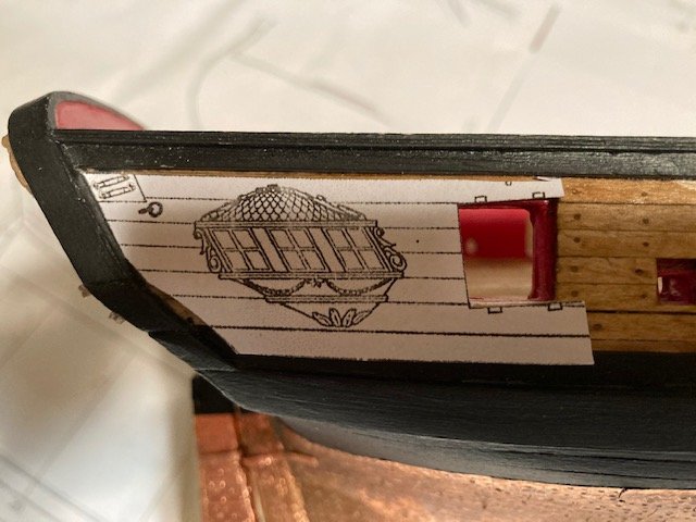
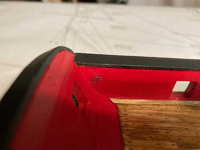
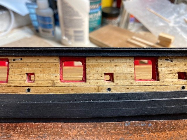
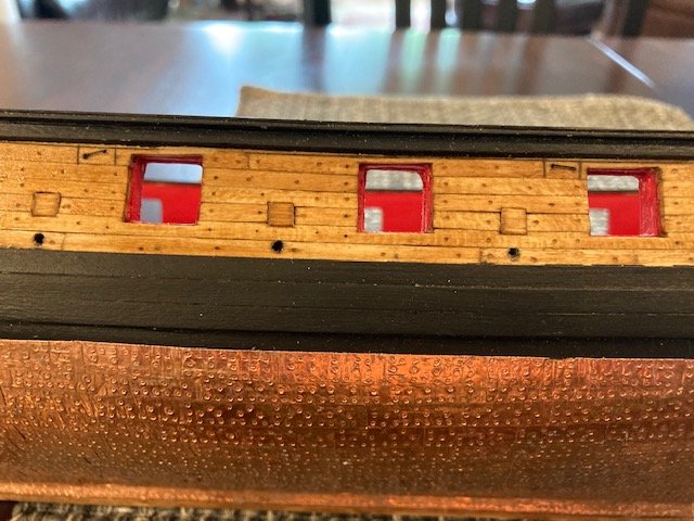
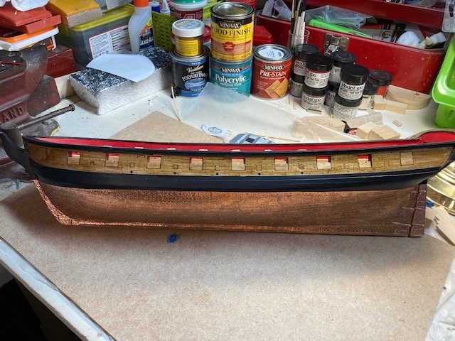
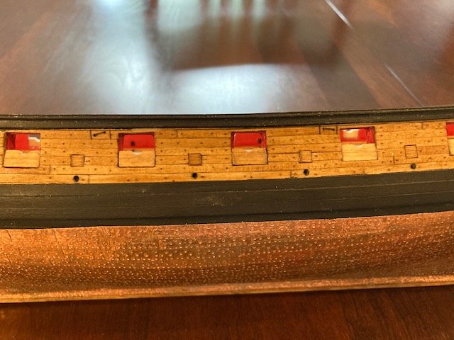
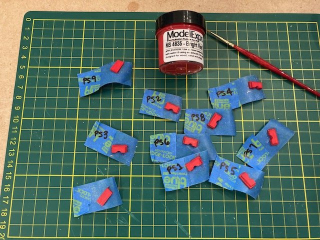
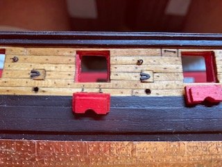
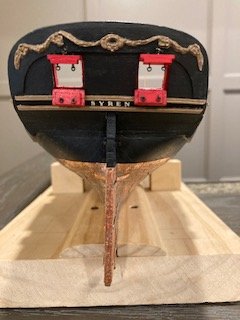
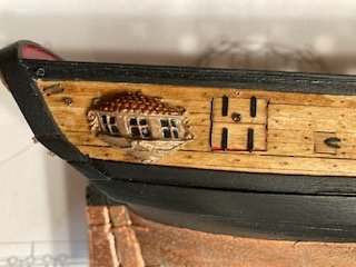
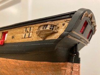
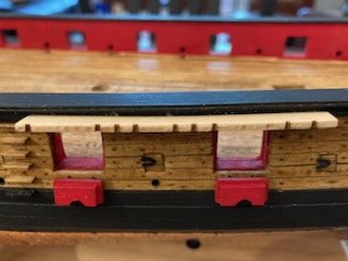
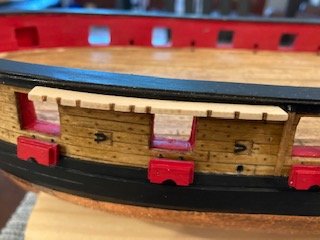
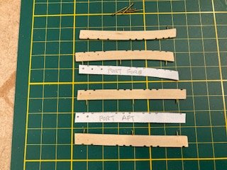
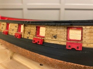
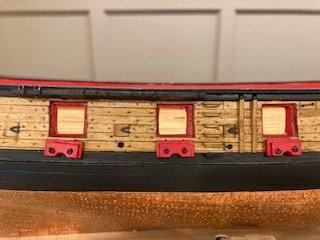
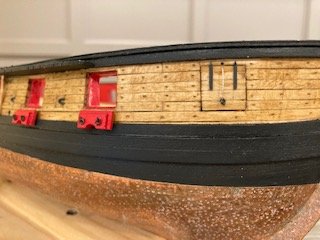
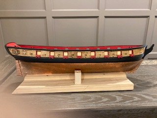
I have completed Chapter 9 – Hull Details. I began by gluing the SYREN photo-etched letters onto the transom. As a guide, I made a copy of the stern elevation on Sheet One, cut out the portion showing the letters SYREN, taped it below the bottom stern molding strip, and then aligned the letters with the cutout. I used a small amount of white glue, which allowed me to position each letter without making a mess of glue. Next, the faux sheaves. I made a photocopy of the starboard side elevation view on Sheet One and cut out the bulwarks. I used this as a template to locate the sheaves. Using my push pin vise, I drilled 0.55 mm holes completely through the bulwarks at the sheave locations - I plan to run the rigging line through the aft holes. I scribed a line between the holes of each sheave and then, using a fine point file, created a groove between the holes. I ran a pencil along the groove to darken, as per the instructions. I may paint the grooves later. While I was at it, I marked the location of eye bolts. I plan to use the eye bolts and rings that came with the kit and to darken them with Brass Black. I ordered Birchwood Casey Brass Black and a stainless-steel tea strainer with mesh bottom from Walmart. While waiting for my Walmart order, I decided to make the sweep port lids. The instructions call for the sweep port lids to be made from a 1/16” x 1/8” basswood strips. I made the sweep ports 1/8” square as per the instruction. With the lip around the ports, they’re 3/16” square. So, I used a 3/16”x 1/16” basswood strip for the lids. I stained the strip with Minwax Golden Oak first. I cut each lid to fit. I didn’t chamfer the back edges of the lids as some other build logs have done because the lids fit tighter without a chamfer. I didn’t paint the back of the lids red because you can’t see the back of the lids when installed. The lids fit tightly without gluing. After installing the lids, I lightly sanded them then applied another coat of stain. I used the “U” shaped hinges provided with the kit. Like the _Sald_ build log, I cut the hinges from the photo etched sheet so that the tab that holds the hinge strap to the photo-etched sheet was in-place. I bent the tab down to use it to secure the hinge to the lid. I added the sweep port hinges to the lids. I didn’t find that leaving the tabs and using them as nails was helpful. So, I clipped them off. I’m not sure whether I want to add the 28 gauge wire to the hinges - they’re so small. For the bulwarks eyebolts I used the kit split rings and eye bolts. I assembled them using a pair of needle nose pliers – tedious work that requires magnifiers. I blackened the eye bolt/split ring assemblies. The split rings match the scale of the plan, but they look too small. The main course and main sheet rings shown in the picture on Page 36 of the instructions appear to be larger. The aft gun port lids and the forward bridle port lids where next. I fashioned the lids using four 1/16” x 1/8” wide basswood strips per lid. The starboard side bridle port is slightly larger, so I had to use one 3/16” x 1/16” and three 1/16” x 1/8” strips. I test fit the lids and left them in-place while I stained the outboard surfaces with Golden Oak stain. I removed the lids, placed them on the sticky side of masking tape, labeled them so I knew which was which, and then painted the inboard surfaces red. The lids have handles on the inboard and outboard sides that are made from eyebolts. Many build logs have added split rings to the eye bolts. The instructions do not call for split rings on the handles. The kit only supplies 20 split rings which isn’t enough if you are going to add rings to the lids. I like the look of the rings on the handles and decided to add them. I tried my hand at making some small split rings by winding some 28-gauge steel wire around the shank of a 1mm diameter drill bit, cutting off the individual rings from the coil, and attaching them to the eye bolts. After making a few, I wasn’t satisfied with the results. The rings weren’t round enough, and it was very tedious and time consuming. For me, it wasn’t worth the effort, so I decided to order some split rings from Model Shipways. I assembled the eye bolts and split rings and blackened them. I added the hinges and eyebolts to the bridle port lids and the aft gun port lids. The photo-etched bridle port hinges are shorter than those depicted on the plans, but I used them anyway. I decided to run the lid lifting rope through the bulwarks rather them over bulwarks, so I drilled a 0.55 mm hole through the bulwarks above the lid. The rope is belayed to a cleat along the inside of the bulwarks. I will add the rope and cleats later. With the gun and bridle port lids complete, I turned my attention to the gun port lids. In making these, I followed the advice of some other build logs and made the lids thicker using two plies of basswood: 1/8” x 1/16” and 3/16” x 1/16”. I, like Dubz build log, didn’t see the logic for a rabbet at the top of the half-lid. The most difficult part for me was making the circular cut out. I kept it simple and used a needle nose file to create the approximate 1/8” diameter half circle. Once I had one lid shaped, I used it as template for the others. I made the port side (PS) lids first. I set the lids in the gun ports and then stained the outboard surface. Note: Other than authenticity, there’s no need to finish the outboard surface of the lids because it won’t be seen when the lids are mounted in the open position. Later, I removed the lids and placed them on the sticky side of masking tape to hold them in-place while I painted the inboard surface red. I labeled the lids PS1, PS2, etc., so that they didn’t get mixed up. Note: I later realized that it’s not necessary to label the gun port lids because they’re all approximately the same width and they’re not going to be installed in the gun ports. I repeated the process for the starboard side lids. The lid eye bolts are not shown on the plans but are shown in the instructions. They appear to be placed at the center of the lids on each side of the half circle. I drilled holes in the port side lids for the eyebolts, and then glued on the hinges. I found that the blackened hinges don’t bond well with white glue on stain. When I bent the hinges, most of them broke off. I re-glued them with CA glue. The hinges look nice, but they won’t see the day of light after the lids are installed. I bent the hinge tabs over and then aligned each lid with the gun port opening and marked the location of the tabs on the bulwarks just below the gun port with a fine point awl. Then, I drilled a 0.55 mm hole at each tab location and test fit the lids. I used the full lid hinge extensions, bent them back and inserted them the holes. Note, I drilled holes for the eye bolts before mounting the lids. I made the gun port lids for the transom a la the other gun port lids, expect they don’t have a circular opening. I tried gluing the blackened hinges to the lids before painting them black to match the transom. The result was the same as the stained lids – the glue didn’t bound. So, I used CA – better results. I drilled a hole through the transom for the lid pull rope. I installed the lid handles and attach the lids. I added the pull rope for the top lid - I’ll add the cleat later. Before moving on from the lids, I was wondering about the bucklers. The instructions say the bucklers were only used during the roughest weather. I’m thinking that the bucklers must have been heavy and difficult to install, especially during rough seas, without dropping them into the ocean. I’m guessing that they must have been lashed to the lower lids before they were “buckled” into position and that the ropes were always in place for this purpose – just saying. On to the quarter badges. I didn’t want to match them to the color of the bulwarks as others have done. Rather, my personal preference was to paint them Antique Gold with Burnt Umber tops. I mixed a little gold with the burnt umber to tint the color. I glued them into position port and starboard – I like the look. Next up, boarding ladders, fenders, chess trees, and fore and main channels. I decided to add the fenders and chess trees first. These are easy to install. I notched-out the top of the fenders and chess trees to fit over the sheer strake. I painted the fenders and chess trees that show above the sheer strake black and stained the rest. I forgot to drill a hole in the chess trees for the fair lead. Fortunately, I was able remove the chess trees without damage, drill a 0.55 mm hole in each one, and re- glue each one in-place. The boarding ladder steps were made from 1/16” x 3/32” basswood strips. I cut the steps from the strip in a miter box. Using my x-acto knife, I made horizontal cut across the face of each step of the approximate width shown on the plan and then made a cut across the underside of the step. I removed the notch and squared iup the cut with a file. Next, a made perdendicular cut on the bottom at each end of the step, removed the notch, and squared it up. I sanded each step with fine sanding stick. To get the proper alignment of the steps on the bulwarks, I marked the spacing of the steps on a piece of masking tape and then placed the tape on the bulwarks. The steps were then glued to the hull at their corresponding mark on the tape. To finish them, I applied Golden Oak stain to the steps above the whale and painted the step on the whale black. The fenders and chess trees were also stained. Lastly, the channels. These are relatively easy to install. I removed the laser cut main and fore channels from the basswood sheet and sanded them to remove the char. To locate the holes in the channels for the eye bolts, I made photocopies of the portside channels from the plans Sheet One, cut them out, and placed them on the laser cut port side channels (for the starboard side channels, I flopped the photocopy over), marked the locations of the eyebolts with an awl first and then drilled a hole at each location. I drilled completely through the channel so that I didn’t have to make the eye bolt shanks so short, making them easier to glue in. The instructions say to make the eyebolts from 28-gauge wire. I used 1/16” eyebolts (MS0428) that I had from another build. I pinned the channels to the sheer strake with brass pins. I drilled three holes in the edge of each channel, snipped the pins and glued them in-place. I marked the locations of the pins on the sheer strake, drilled a hole at each location, and glued the channels in-place. I painted the channels on-ship and added the eye bolts. Oh, one more thing, I assembled the eye bolts and split rings, blackened them, and installed them on the lids. Now, it’s on to Chapter 10.
- 157 replies
-
- 2
-
-
- model shipways
- syren
- (and 1 more)
-
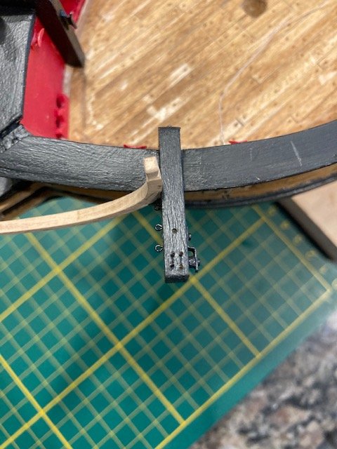
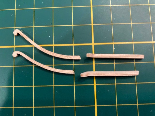
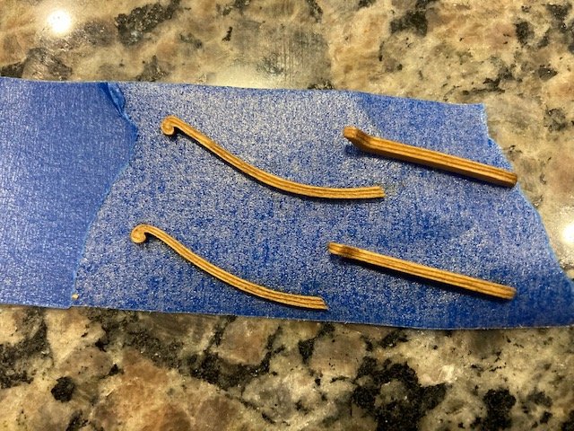
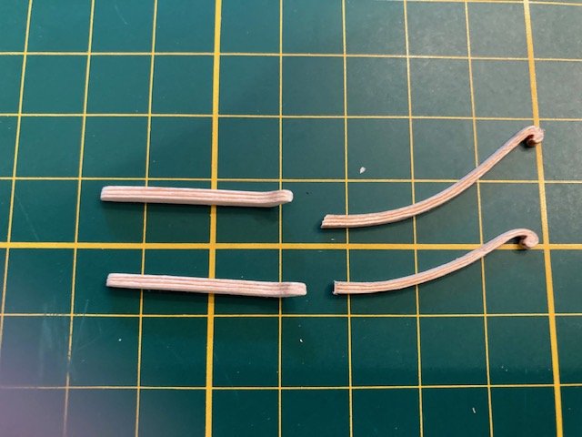
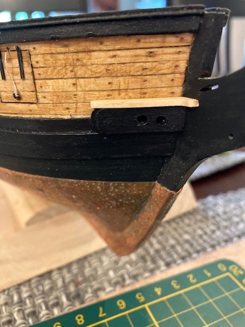
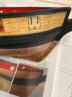
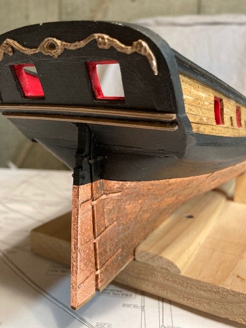
Continuing with Chapter 8, I completed copper plating the rudder – I had previously shaped the rudder, so it was ready for copper plating. I fashioned the iron strap that the two rudder pendant eye bolts are secured to from copper tape. I doubled up the tape and cut an appropriately wide and long strip. I drilled a hole in the strip on each side of the rudder and glued the eye bolts. I used the small (0.75mm) brass eyebolts furnished with the kit. I fashioned the gudgeons and pintles from the 1/16” brass strips furnished with the kit. My approach was to follow the instructions and to "keep it simple stupid" (KISS). I'm not into soldering, so making working hinges was not an option. Besides, I think a lot of the detail isn't visible whence the gudgeons and pintels are assembled. To get the length of the gudgeons and pintles I scaled the length on the standing rigging plan, multiplied by two, and allowed for the width of the keel and the rudder. I cut the brass strip to the required lengths and then shaped them by bending them around the keel and the rudder. I cut the pintel pins from 22-gauge wire furnished with the kit. I cut the length a little longer then the width of two 1/16” brass strips. I found that a nail clipper makes a good clean cut. I’m not into soldering, so I glued the pins to the pintles with CA glue – not an easy task. I set the pintels aside while the glue dried and later applied a small amount of CA to further secure the pins. Next, I covered the brass strips with copper tape. I used the dressing belt stamp and trimmed it to the width of the brass stripe. I glued (CA) the pintles on the rudder, making sure they are perpendicular to the keel. To get the correct angle, I laid the rudder down on the plan sheet and applied a narrow strip of masking tape on the rudder to use as a guide. Next, I slid the gudgeons behind the pintle pins to test fit the rudder assembly on the hull. I painted the topmost gudgeon and pintle black. Attaching the gudgeons to the hull was a little tricky. I glued the topmost gudgeon to the hull stem first. Then, with the other gudgeons behind the pintle pins, I secured them a little CA glue at the gudgeon/pintel pin interface so that they wouldn’t flop around. I made sure the gudgeons were perpendicular to the stem and glued them in-place. The rudder copper has not yet been treated with vinegar and salt. You can see the difference in the patina of the copper. I'm need sure yet whether I like the patina of the hull, although it does have an aged look to it IMO. This concludes Chapter 8. At this point, I’m 13 weeks into the build.
.jpg.e926219ee83058a12923b67a8694a158.jpg)
.jpg.d3d59db7634952c67bcb994c09a4160b.jpg)
.jpg.2c420ef18ddfc872d3f5a45d8561b990.jpg)
.jpg.4dac83ca465f502ad77df4191d87d436.jpg)
.jpg.1223c9ace523c32d201c66a240eeda5a.jpg)
.jpg.29fb475efee068b052f362d3b8032ca3.jpg)
- 157 replies
-
- 3
-
-
- model shipways
- syren
- (and 1 more)
-
Thanks. It's fairly straight. Completing the plating is more a sigh of accomplishment than relief.
- 157 replies
-
- 1
-
-
- model shipways
- syren
- (and 1 more)