

abelson
-
Posts
467 -
Joined
-
Last visited
Content Type
Profiles
Forums
Gallery
Events
Everything posted by abelson
-
 Nice, clean work on the deck and bulwarks. Looking good!
 -
Been following your build lately. Your carronade rollers look nice. I admire your metal work. Patience is a virtue. I have found that jumping around from chapter to chapter breaks the monotony and is a good diversion. Delaying only puts off the inevitable, though.
-
Serving of the ropes looks good - it's always a difficult task.
- 950 replies
-
- 2
-

-
- syren
- model shipways
- (and 1 more)
-
Very innovative approach to making the carronade wheels and brackets.
-
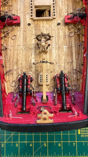
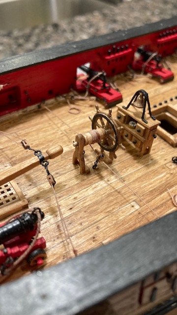
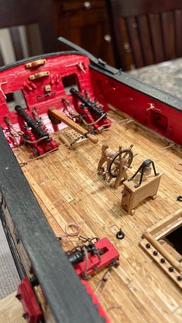
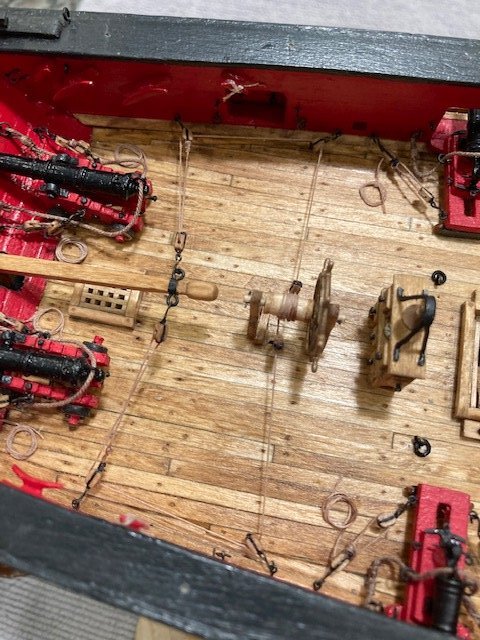
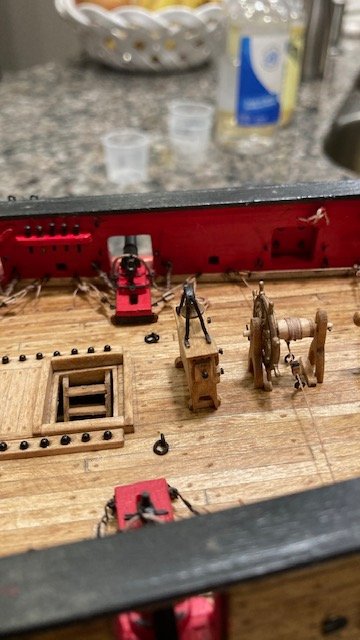
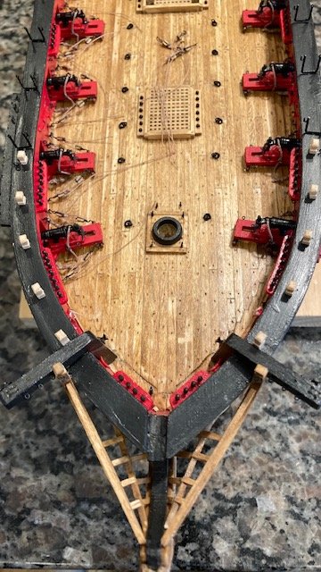
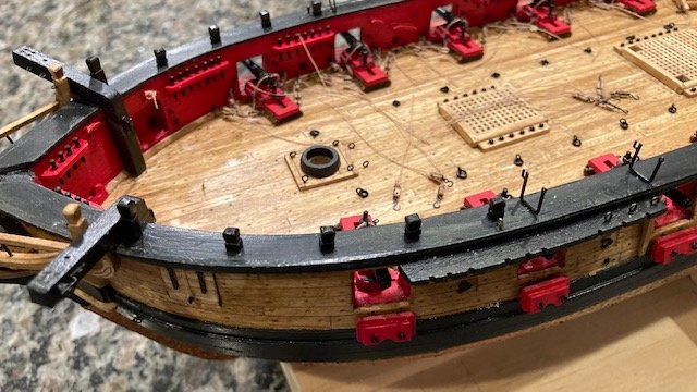
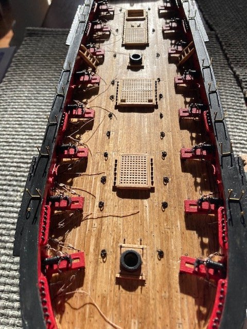
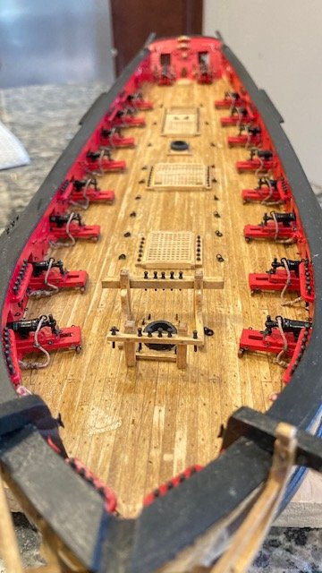
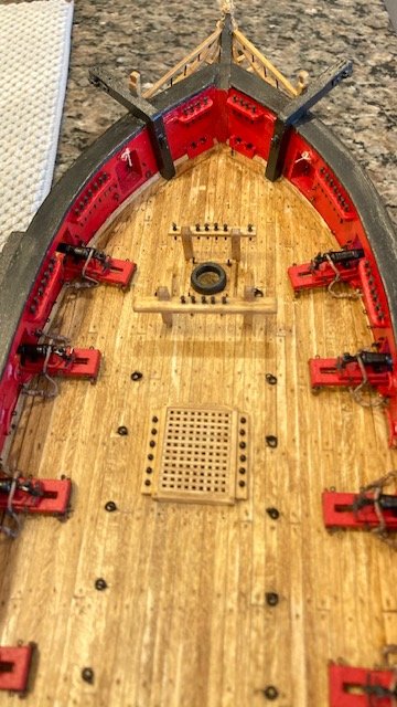
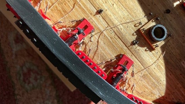
I finished the carronade lower tackles. I had mentioned that I didn’t like the look of the upper tackles because the blocks are too close together with the hooks stropped to the blocks and seizing. So, rather than do the tedious task of making up 64 blocks and tackles, I opted to omit the upper tackles. The loose ends of the lower tackles were glued to the deck and cut off. I made some simple rope coils for the long cannons and glued them to the deck before rigging the steering mechanism. The coils were made by wrapping .008” tan rope around a 3/16” dowel 4 or 5 times and applying some watered down carpenters glue to it. When dry, the coil was slipped off the dowel, flattened, and the loose ends trimmed. Rigging the steering mechanism: Like some other build logs, I added a block hooked to an eye bolt on each side at the base of the ship’s wheel to keep the line lower to the deck. The rigging was easier than I expected. I stropped hooks to 3/32” blocks. I rigged the steering mechanism as per the instructions except for the blocks at the base of the ship's wheel. I seized a “generous length” .008” tan line to a block hooked to an eye bolt along the port side waterway aft of the last gun port. I reeved the line through a block hooked to a ring on the tiller and then down to the originating block. From there I reeved the line through the blocks and around the drum. I applied a little CA to the blocks to keep the line in tension. I wrapped the line around the drum six (6) times. I applied CA to each wrap to secure the line and make it easier to wrap. I completed the rigging by reeving the line in the reserve order. Next up, complete the rope coils, permanently attach the deck fittings, and finish the hammock cranes. Merry Christmas to all!
- 157 replies
-
- 3
-
-
- model shipways
- syren
- (and 1 more)
-
Excellent, finely detailed, product. BTY, the deck looks authentic - great job on that too.
- 950 replies
-
- 1
-
-
- syren
- model shipways
- (and 1 more)
-
Nice work on the long boat. I'll definitely be referring to your build log when I reach the longboat stage.
- 950 replies
-
- 1
-
-
- syren
- model shipways
- (and 1 more)
-
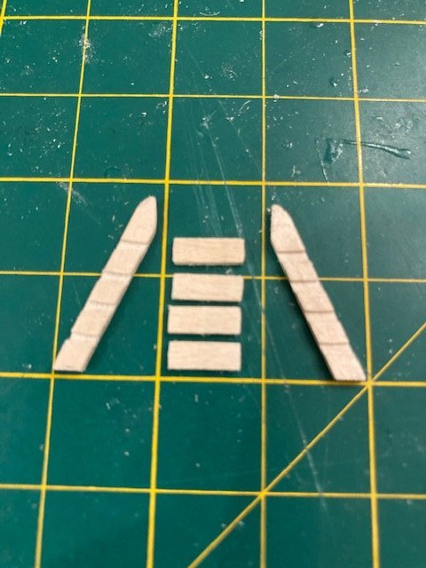
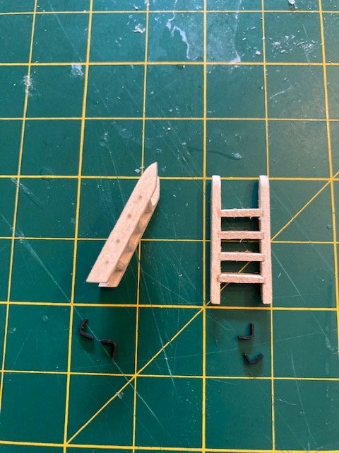
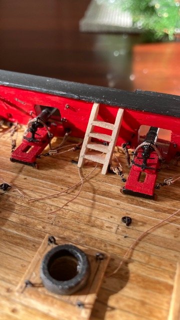
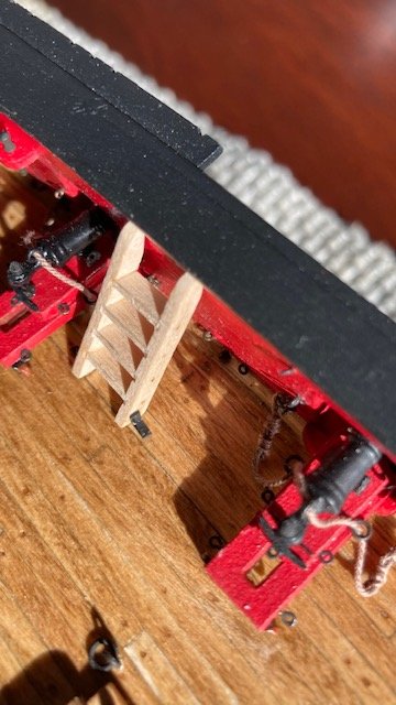
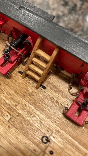
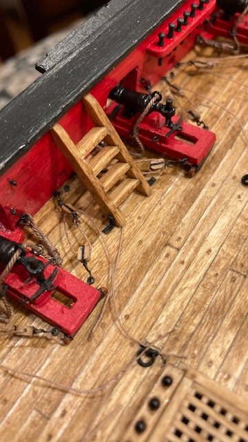
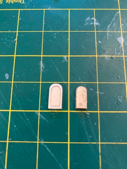
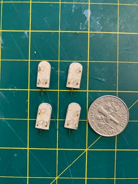
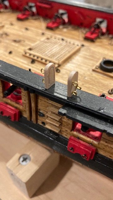
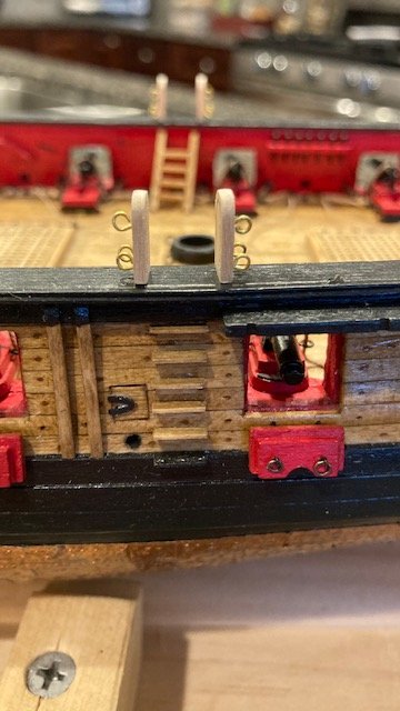
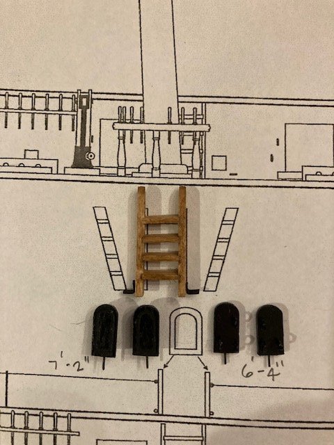
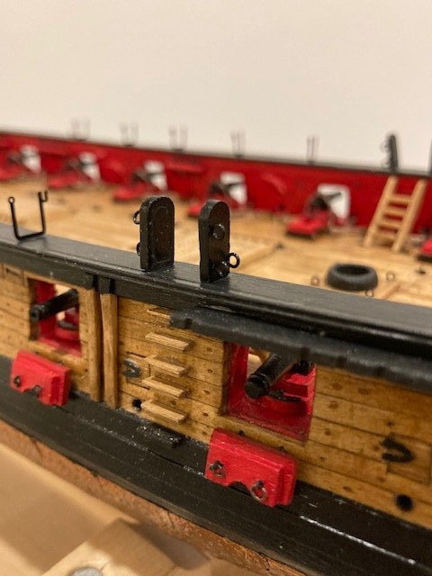
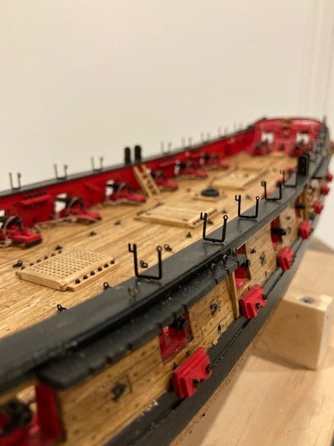
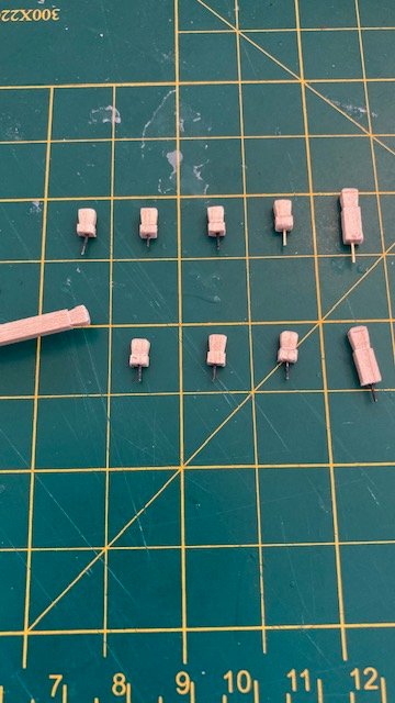
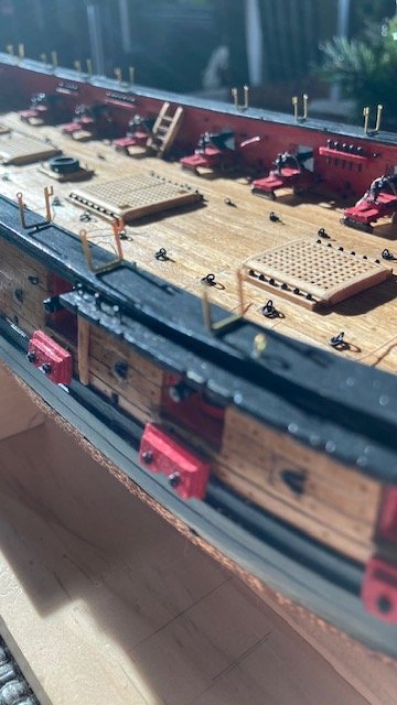
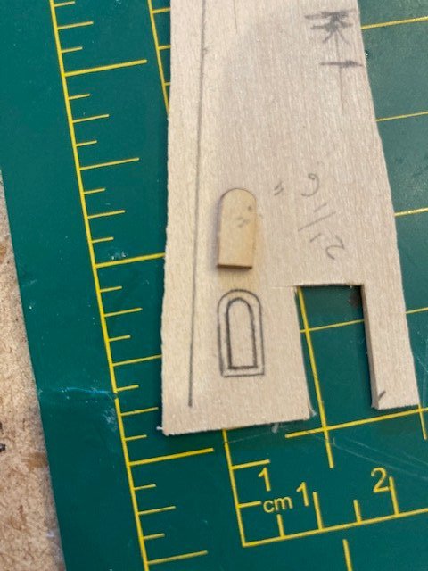
I had to order more .008” rope from Syren to complete the lower carronade tackles. While awaiting delivery of my order, I decided to make the midship boarding ladders. I wanted to beef up the ladders so I made the side rails and steps from a 3/32”x 1/8” basswood strip. I used the detail on Sheet 4 as a guide for marking the steps. Using a knife, I made a vertical cut along each step line. Turning the strip on its side, I made a cut between the two vertical cuts along the midpoint of the strip. I removed the notch with a small square file and then evened the grooves (notches) using a flat file that has teeth on the edges. The steps were then glued in place. I filed the ladder to square up all the edges and rounded the top of the side rails. I added some brass angles (painted black) to the side rails to secure the ladders to the deck. The carronade tackles interfere with the ladders or vice versa. This is not obvious from the plans. The ladders were stained Golden Oak, and will be glued in-place later. I jumped ahead to Chapter 14 and laid out the photo etched hammock cranes. Using Plan Sheet 4 as a guide, I determined the locations of the boarding panels and marked them on the cap rail. I scaled the distance between the hammock cranes from Plan Sheet 4 and marked them on the cap rail. [Note: Do not use Plan Sheet 5 to locate the hammock cranes as there is a discrepancy between Sheet 4 and Sheet 5 - the spacing of the fore most hammock cranes on Sheet 5 does not agree with Sheet 4.] I drilled a hole mid rail at each hammock crane location. I cut the photo etched hammock cranes free leaving the bottom prong which is inserted into the pre-drilled hole on top of the cap rail. I also pre-drilled holes in the top of the cap rail for the eyebolts that the hammock crane rigging line will be seized to. I test fit, removed, and painted the hammock cranes black. I’m holding off on installing the hammock cranes and boarding panels until I complete rigging the carronades and tiller steering mechanism and installing all of the deck fittings. Next, I fabricated the boarding panels. The laser cut panels are 3/16” wide. Because my rail cap is just under 3/8” wide the laser cut panels look too small - I see, now, the importance of keeping the rail cap 3/16” wide. I decided to make the boarding panels slightly wider. I traced the outline of the laser cut panels onto a piece of 1/16” basswood. I cut along the outer edge of the pencil line. The basswood panels are slightly larger than the laser cut panels (see photo). Next, I traced the profile of the molding around the boarding panel, scored the pencil line with my x-acto knife, and then ran a fine point awl along the scored line to simulate a raised panel. The raised panel effect is not obvious when the boarding panels are painted black. The boarding panels will be pinned to the cap rail. Three (3) eyebolts were glued into pre-drilled holes in each panel. The rigging lines for the hammock netting will be seized to these eye bolts. Keeping with Chapter 14, the timberheads were made using a 3/32” x 1/8” basswood strip, as per the instructions. The timberheads were shaped to simulate the profile on the plans. Pins were added to secure them on the cap rail. I cut out the port and starboard side cap rails from the Plans and used them as templates to mark the location of the timberheads. The timber heads were painted black and temporarily pinned to pre-drilled holes in the cap rail. I use an iPhone to take photographs, so the detail in the timberheads is not clear. My shipment of .008” rope arrived so I plan to jump back to Chapter 11 and complete the lower tackles for the starboard side carronades. Stay tuned for another update.
- 157 replies
-
- 8
-
-
- model shipways
- syren
- (and 1 more)
-
Great job on the hammock netting. Love your photos - they give a nice perspective of your fine work. I like the look of the hammocks and agree that they do look a bit bulky. I will be interested in how you made them.
- 950 replies
-
- 1
-
-
- syren
- model shipways
- (and 1 more)
-
Nice detailed work on the cap rail.
-
Nice work on the davits and timber heads. The transom looks great.
- 950 replies
-
- 1
-
-
- syren
- model shipways
- (and 1 more)
-
Looking real good. I used the pin stripe tape for the bow sprit and painted it black.
-
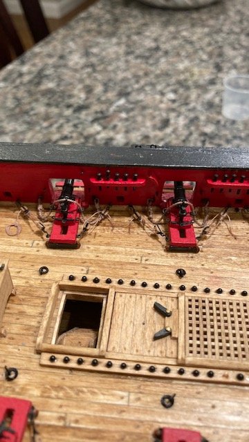
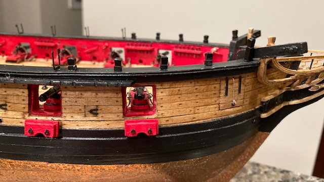
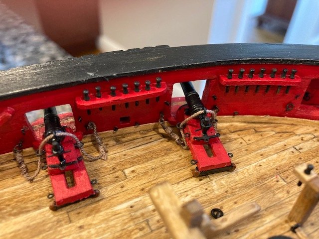
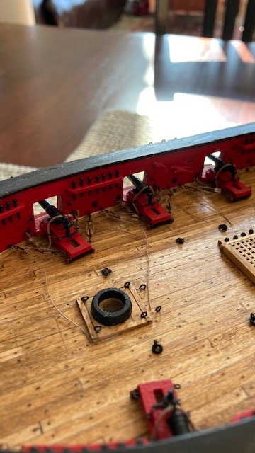
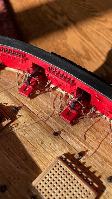
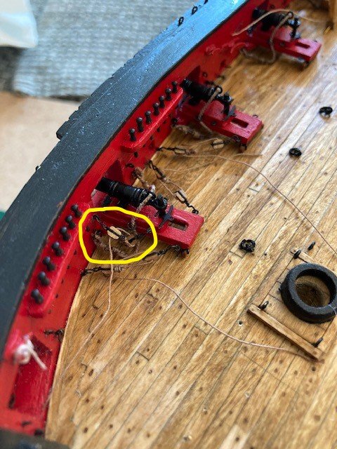
I completed the mundane task of rigging the carronade breech lines. It requires a lot of patience and good magnifying glasses. I took a reprieve around the Thanksgiving holiday to rest my eyes and re-energy. Rigging the Breach Lines: I used Syren tan .025” brown rigging line for the breech ropes and .008” for the seizing. I rigged the breech lines with the sleds off-ship. I cut all the breech lines about 3” long. I made the breech line knots similar to the long gun breech lines, except that I double seized them. I completed one end of the line and then ran the loose end through the breech line ring, carronade eye, and the other breech line ring. I repeated the process for the rest of the carronades. Then, I made the knot on the opposite side of each carronade. With the breech lines done. I glued one breech line eye bolt/split ring into the bulwark and then glued the sled in-place - I used white glue because it allowed me time to move the sled into proper position. While the glue was drying, I repeated the process for each succeeding carronade. When the glue was dried, I glued the opposite side breech line eye bolt/split ring into the bulwark. In the process of installing the sleds, some the photo-etched pieces came off, and I broke one of the sleds by pushing on it too hard. All easily fixed by gluing, however. For me, gluing the eyebolts to the bulwark was the most difficult part. I’m satisfied with the breech lines but, In hindsight, I wouldn’t have double seized them because it makes the knots too long for short length between the bulwark and the sled. Rigging the Tackles: The tackle lines were made up same as the long guns. I completed the tackles on one carronade and decided that I didn't like the look of the upper tackle because the blocks are too close together (see photo). To increase the length between the blocks, I’ll need to replace the hooks with shorter hooks. Fortunately, I only made up enough blocks to rig 8 of the 16 carronades. So, for now, I will only rig the lower tackles. As per the instructions, the tackles were pulled to tighten them and a drop of CA was applied to the block at the bulwark to hold the tension - so far so good. The rope coils will be made later.

- 157 replies
-
- 2
-
-
- model shipways
- syren
- (and 1 more)
-
I had a similar problem. My cap rail with the 1/16" strip along the outboard edge is 3/8" wide. In the scheme of things, the added width isn't noticeable, especially after it's painted black.
-
Timber heads look good. Maybe tweak the starboard side one second from the left a little bit?
-
Very nice, crisp and clean work. Your perfectionism shows.
-
Excellent work, and photographs too. I like the coloration.
-
Your build is coming along nicely. Regarding the transom, to avoid the problem curve, I trimmed the first counter plank (5/32” x 1/16”) to match the transom. I beveled the edge of the 5/32” plank that will abut the 1/8” x 1/16” plank. The transom edge is already beveled. I know this is an after thought, but it may be helpful to others following your build. Keep up the good work and persevere.
- 436 replies
-
- 1
-
-
- Syren
- Model Shipways
- (and 1 more)
-
Wow, that's a lot work there. I'm admiring your build and stealing some of your ideas. Verrrrry professional.
-
Nice job on the tenons around the mast. Great idea on drilling counter clockwise - wish I had thought of that.
- 950 replies
-
- 1
-
-
- syren
- model shipways
- (and 1 more)
-
Nice detail on the pumps - looks great. I like the effect.
- 950 replies
-
- 3
-
-
- syren
- model shipways
- (and 1 more)
-
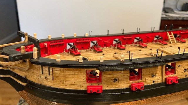
Nice detail on the deck fittings, especially the gallows bitts. The deck fitting are a nice break from the carronade rigging. Looking crisp and clean.
